EP3670358A1 - System und verfahren zur bestimmung des abstands zwischen zwei teilen mithilfe von wirbelstrom-sensoren - Google Patents
System und verfahren zur bestimmung des abstands zwischen zwei teilen mithilfe von wirbelstrom-sensoren Download PDFInfo
- Publication number
- EP3670358A1 EP3670358A1 EP19218104.8A EP19218104A EP3670358A1 EP 3670358 A1 EP3670358 A1 EP 3670358A1 EP 19218104 A EP19218104 A EP 19218104A EP 3670358 A1 EP3670358 A1 EP 3670358A1
- Authority
- EP
- European Patent Office
- Prior art keywords
- parts
- assembly
- spacing
- positioning
- eddy current
- Prior art date
- Legal status (The legal status is an assumption and is not a legal conclusion. Google has not performed a legal analysis and makes no representation as to the accuracy of the status listed.)
- Granted
Links
- 238000000034 method Methods 0.000 title claims description 25
- 238000000926 separation method Methods 0.000 title 1
- 238000012545 processing Methods 0.000 claims description 8
- 230000015572 biosynthetic process Effects 0.000 claims description 7
- 238000011960 computer-aided design Methods 0.000 claims description 3
- 238000005259 measurement Methods 0.000 description 4
- 238000010586 diagram Methods 0.000 description 3
- 238000012795 verification Methods 0.000 description 3
- 239000000523 sample Substances 0.000 description 2
- 238000000576 coating method Methods 0.000 description 1
- 238000005260 corrosion Methods 0.000 description 1
- 230000007797 corrosion Effects 0.000 description 1
- 238000001514 detection method Methods 0.000 description 1
- 238000005553 drilling Methods 0.000 description 1
- 238000009434 installation Methods 0.000 description 1
- 239000000463 material Substances 0.000 description 1
- 239000002184 metal Substances 0.000 description 1
- 238000009659 non-destructive testing Methods 0.000 description 1
- 239000000758 substrate Substances 0.000 description 1
Images


Classifications
-
- B—PERFORMING OPERATIONS; TRANSPORTING
- B64—AIRCRAFT; AVIATION; COSMONAUTICS
- B64F—GROUND OR AIRCRAFT-CARRIER-DECK INSTALLATIONS SPECIALLY ADAPTED FOR USE IN CONNECTION WITH AIRCRAFT; DESIGNING, MANUFACTURING, ASSEMBLING, CLEANING, MAINTAINING OR REPAIRING AIRCRAFT, NOT OTHERWISE PROVIDED FOR; HANDLING, TRANSPORTING, TESTING OR INSPECTING AIRCRAFT COMPONENTS, NOT OTHERWISE PROVIDED FOR
- B64F5/00—Designing, manufacturing, assembling, cleaning, maintaining or repairing aircraft, not otherwise provided for; Handling, transporting, testing or inspecting aircraft components, not otherwise provided for
- B64F5/10—Manufacturing or assembling aircraft, e.g. jigs therefor
-
- B—PERFORMING OPERATIONS; TRANSPORTING
- B23—MACHINE TOOLS; METAL-WORKING NOT OTHERWISE PROVIDED FOR
- B23P—METAL-WORKING NOT OTHERWISE PROVIDED FOR; COMBINED OPERATIONS; UNIVERSAL MACHINE TOOLS
- B23P19/00—Machines for simply fitting together or separating metal parts or objects, or metal and non-metal parts, whether or not involving some deformation; Tools or devices therefor so far as not provided for in other classes
- B23P19/10—Aligning parts to be fitted together
-
- B—PERFORMING OPERATIONS; TRANSPORTING
- B64—AIRCRAFT; AVIATION; COSMONAUTICS
- B64F—GROUND OR AIRCRAFT-CARRIER-DECK INSTALLATIONS SPECIALLY ADAPTED FOR USE IN CONNECTION WITH AIRCRAFT; DESIGNING, MANUFACTURING, ASSEMBLING, CLEANING, MAINTAINING OR REPAIRING AIRCRAFT, NOT OTHERWISE PROVIDED FOR; HANDLING, TRANSPORTING, TESTING OR INSPECTING AIRCRAFT COMPONENTS, NOT OTHERWISE PROVIDED FOR
- B64F5/00—Designing, manufacturing, assembling, cleaning, maintaining or repairing aircraft, not otherwise provided for; Handling, transporting, testing or inspecting aircraft components, not otherwise provided for
- B64F5/60—Testing or inspecting aircraft components or systems
-
- G—PHYSICS
- G01—MEASURING; TESTING
- G01N—INVESTIGATING OR ANALYSING MATERIALS BY DETERMINING THEIR CHEMICAL OR PHYSICAL PROPERTIES
- G01N27/00—Investigating or analysing materials by the use of electric, electrochemical, or magnetic means
- G01N27/72—Investigating or analysing materials by the use of electric, electrochemical, or magnetic means by investigating magnetic variables
- G01N27/82—Investigating or analysing materials by the use of electric, electrochemical, or magnetic means by investigating magnetic variables for investigating the presence of flaws
- G01N27/90—Investigating or analysing materials by the use of electric, electrochemical, or magnetic means by investigating magnetic variables for investigating the presence of flaws using eddy currents
- G01N27/9006—Details, e.g. in the structure or functioning of sensors
-
- G—PHYSICS
- G01—MEASURING; TESTING
- G01N—INVESTIGATING OR ANALYSING MATERIALS BY DETERMINING THEIR CHEMICAL OR PHYSICAL PROPERTIES
- G01N27/00—Investigating or analysing materials by the use of electric, electrochemical, or magnetic means
- G01N27/72—Investigating or analysing materials by the use of electric, electrochemical, or magnetic means by investigating magnetic variables
- G01N27/82—Investigating or analysing materials by the use of electric, electrochemical, or magnetic means by investigating magnetic variables for investigating the presence of flaws
- G01N27/90—Investigating or analysing materials by the use of electric, electrochemical, or magnetic means by investigating magnetic variables for investigating the presence of flaws using eddy currents
- G01N27/9013—Arrangements for scanning
- G01N27/902—Arrangements for scanning by moving the sensors
-
- B—PERFORMING OPERATIONS; TRANSPORTING
- B23—MACHINE TOOLS; METAL-WORKING NOT OTHERWISE PROVIDED FOR
- B23P—METAL-WORKING NOT OTHERWISE PROVIDED FOR; COMBINED OPERATIONS; UNIVERSAL MACHINE TOOLS
- B23P2700/00—Indexing scheme relating to the articles being treated, e.g. manufactured, repaired, assembled, connected or other operations covered in the subgroups
- B23P2700/01—Aircraft parts
-
- G—PHYSICS
- G01—MEASURING; TESTING
- G01N—INVESTIGATING OR ANALYSING MATERIALS BY DETERMINING THEIR CHEMICAL OR PHYSICAL PROPERTIES
- G01N2291/00—Indexing codes associated with group G01N29/00
- G01N2291/26—Scanned objects
- G01N2291/269—Various geometry objects
- G01N2291/2694—Wings or other aircraft parts
-
- G—PHYSICS
- G01—MEASURING; TESTING
- G01N—INVESTIGATING OR ANALYSING MATERIALS BY DETERMINING THEIR CHEMICAL OR PHYSICAL PROPERTIES
- G01N27/00—Investigating or analysing materials by the use of electric, electrochemical, or magnetic means
- G01N27/72—Investigating or analysing materials by the use of electric, electrochemical, or magnetic means by investigating magnetic variables
- G01N27/82—Investigating or analysing materials by the use of electric, electrochemical, or magnetic means by investigating magnetic variables for investigating the presence of flaws
- G01N27/90—Investigating or analysing materials by the use of electric, electrochemical, or magnetic means by investigating magnetic variables for investigating the presence of flaws using eddy currents
Definitions
- the present invention relates to a system and method for assembling at least two parts such as parts forming the fuselage or the wing of an aircraft.
- the invention thus finds its application in the assembly operations of large parts used for the formation of the fuselage or the wing of an aircraft.
- the parts to be assembled may be sections of the fuselage. During their assembly, the parts are brought into contact and then fixed together. In general, the parts are positioned in superposition at an assembly area where the fixing of the parts is implemented.
- the assembly of the parts forming the fuselage or the wing of the aircraft is carried out with rigor and precision and the spacing between the assembled parts, at the level of the assembly zone must not exceed predefined values for, among other things, ensure stable attachment of parts.
- positioning tools implement the positioning of the parts one close to the other, or in close proximity, in the assembly area.
- the positioning tools are assisted by means of assistance, or assistance, in positioning.
- the positioning assistance or assistance means typically include length measuring instruments such as tracking lasers, also known as tracking or reading lasers (“laser trackers” in English terminology).
- the length measuring instruments are positioned and configured to emit signals intended to reach targets located in the parts to be assembled.
- the targets can be landmarks in the parts or elements positioned on the parts to be assembled, for example reflective targets.
- the tracking laser interacts with the targets so that the positioning assistance or assistance means determine the positioning of the targets and consequently of the parts to be assembled.
- the positioning tools are thus guided by the positioning assistance means until the parts are arranged one near the other in a predefined assembly position.
- the predefined assembly position must be understood as a position of the parts in which the parts can be joined together.
- an operator manually evaluates the spacing between the two parts at the level of the assembly zone.
- this value is defined as the local distance between the skin of two fuselage sections to be assembled.
- the operator can use either calibrated shims or devices fitted with probes measuring the distance between the parts.
- probes In the case of probes, they are introduced between the parts to carry out this type of measurement. In both cases, the spacing between the two parts is measured by so-called intrusive acquisitions, that is to say that the action of measuring can interact with the assembly or in other words, modify the spacing of the skins during the measurement operation.
- This operation is repeated as many times as necessary and, depending on the results obtained, the parts are moved or not by the positioning tools so that the parts are assembled without exceeding predetermined spacing values.
- the parts are positioned so as not to exceed a predetermined spacing value between them, the parts are joined together, for example by pinning, then by drilling and riveting.
- the checking of the spacing of the parts is thus an operation carried out locally and manually by an operator.
- the present invention aims to reduce operator intervention in order to improve the assembly processes of parts, such as two parts of the fuselage or wing of an aircraft.
- the present invention relates, according to a first aspect, to a system for assembling at least two parts, in particular parts forming the fuselage or the wing of an aircraft, comprising means for assisting in positioning the parts and control means configured to control positioning tools as a function of signals from the positioning assistance means so as to juxtapose said at least two parts at an assembly zone.
- the assembly system further comprises a set of eddy current sensors intended to be positioned in at least one of said at least two parts, said control means being configured for the acquisition of signals from the sensors of the set of sensors, to determine the spacing of said at least two parts at the assembly area from the acquired signals, and to generate commands intended for positioning tools to move at least one of the parts if the spacing does not meet a predetermined criterion.
- the spacing between the parts can be checked automatically during the assembly operations of the parts. The intervention of an operator is thus avoided, which reduces the duration of assembly operations and improves the reliability of checks.
- the duration of a two-part assembly operation is further reduced since several spacing measurements can be taken at the same time at different locations.
- the signals from the sensors, as well as the determined spacings can be recorded so as to have traceability of this data in assembly operations.
- the eddy current sensors make it possible to implement the determination of the spacing by non-destructive testing methods (known as CND methods).
- eddy current sensors are used today for certain verifications in the aeronautical field such as the detection of cracks or corrosion zones, the measurement of the thickness of metal substrates or coatings but are not used to measure gaps in assembly operations.
- the present invention relates according to a third aspect, the use of an assembly system according to the invention and implementing the assembly method according to the invention for the formation of a fuselage or a wing of aircraft.
- the assembly method and the use of the assembly system have characteristics and advantages similar to those described above in relation to the assembly system.
- the invention finds its application in assembly operations of large parts used for the formation of an aircraft fuselage or wing.
- parts forming part of an aircraft fuselage such as fuselage sections.
- the description applies to other parts forming part of an aircraft, for example to parts forming the wing of the aircraft or any other part having a skin where a predetermined spacing between the skin and that of a other room is tolerated.
- the figure 1 represents a part of a fuselage 100 of an aircraft in a phase of assembling the different parts forming the fuselage 100.
- the fuselage is a monocoque fuselage.
- the figure 1 represents the constraints of positioning a longitudinal seam.
- Parts A, B must be joined according to a border plan. This boundary plane defines the positioning of the parts A, B relative to each other and the spacing tolerated between them. As will be described below, the spacing or backlash is determined by the eddy current sensors.
- the fuselage 100 is supported by support elements 200.
- the parts forming the fuselage 100 are assembled together using an assembly system. An embodiment of the assembly system will be described below with reference to figures 1 and 2 .
- FIG. 1 A detail of the fuselage is shown in the figure 1 .
- This detail represents the assembly zone 300 of the parts A, B or zone where the parts A, B will be joined together.
- the parts A, B are juxtaposed or positioned in immediate proximity at the level of the assembly zone 300.
- a spacing d is present between the parts A, B in this assembly zone 300.
- the assembly system of at least two parts A, B comprises means for assisting the positioning 400 of the parts A, B generating signals relating to the position of the parts A, B. These signals are used to control the movement of positioning tools in order to position the parts A, B at particular locations.
- the positioning tools, guided by positioning assistance means, are means known to those skilled in the art.
- the positioning tools (not shown in the figure) are used for assembling or fitting parts. It will be noted that when the parts have to be assembled so as to be fixed relative to each other, the positioning tools position the parts so as to juxtapose them or to position them in immediate proximity at the level of the zone d assembly 300.
- the parts A, B are fixed together at an assembly zone 300.
- the assembly zone 300 of a part corresponds to the part of the part which is fixed to another part, that is to say the zone or part where fixing means are going to be installed so as to join a piece A to another piece B.
- the positioning tools are guided in their operation by control means 500 generating commands intended for the positioning tools as a function of the signals coming from the positioning assistance tools 400.
- the control means 500 are configured for controlling the operation of the assembly system.
- the positioning aid 400 for the parts A, B comprises a length measuring instrument 40 making it possible to determine the position of at least one part A, B.
- the positioning aid means 400 can determine the position of the second part which will be assembled to the first part.
- the positioning means 400 for the parts also comprise at least one target intended to be positioned on at least one of the parts A, B.
- a target can be formed by a predefined location in at least one of the parts A, B, or can comprise an element intended to be positioned on at least one of the parts A, B.
- the length measuring instrument 40 interacts with the targets so as to determine the position of at least one of the parts A, B.
- the positioning tools are controlled as a function of the positions determined to position the parts A, B in assembly position.
- the positioning tools and the positioning aid 400 are known to those skilled in the art and will not be described further here.
- the assembly system comprises means for determining the spacing between the two parts A, B at the level of the assembly zone 300 of the parts A, B.
- the determination means comprise a set of eddy current sensors 20.
- a single sensor 20 is shown diagrammatically in the figure 1 on the detail of the assembly area 300.
- the determination means comprise several eddy current sensors 20 distributed in the surface of the parts A, B at the level of the assembly area 300 in order to reliably determine the spacing d between the two parts A, B.
- the eddy current sensors 20 are linked to the positions of the targets of the positioning aid 400.
- the positioning of targets is governed by a control plan.
- the control plan includes rules and dimensions allowing the correct positioning of the parts.
- the control plan defines the predetermined spacing.
- the installation of the assembly system is then facilitated as soon as the targets of the positioning means 400 and the eddy current sensors 20 are positioned on the parts A, B at the same time.
- the eddy current sensors are positioned directly on the parts, independently of the targets, by non-permanent fixing means such as collages or flexible tools to be positioned on the structure.
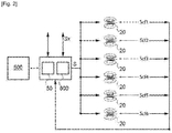
- the figure 2 illustrates elements of the assembly system, in particular means for determining the spacing d according to one embodiment.
- the assembly system in particular the means for determining the spacing d of the two parts A, B, includes means for generating eddy currents, acquiring and processing 50 of signals from eddy current sensors 20.
- the means for generating eddy currents, for acquiring and processing 50 signals from the eddy current sensors 20 will be called generation means 50 in the description which follows.
- the figure 2 represents, by way of non-limiting example, six eddy current sensors 20.
- the number of sensors 20 can be different, the number being determined on a case-by-case basis as a function of the parts to be assembled.
- Eddy current sensors are linked via a computer-aided design tool (known as a CAD tool).
- the CAD tool is implemented by control means 500.
- the eddy current generator 50 is configured to generate a signal S intended for the eddy current sensors 20 of the assembly.
- the signal is for example an electromagnetic wave.
- a single eddy current sensor 20 is shown.
- the assembly system further comprises multiplexing means 600 disposed between the generation means 50 and all of the eddy current sensors 20.
- the multiplexing means 600 allow the electromagnetic wave generated by the generation means 50 reaches each of the eddy current sensors 20 arranged on at least one of the two parts A, B.
- the incidence of the electromagnetic wave S generated by generation means 50 on each of the eddy current sensors 20 modifies at least one of the parameters of the sensors 20.
- the eddy current sensors 20 include a coil and generate in response to the reception of the electromagnetic wave S a signal S CF representative of a variation in impedance of the coil, for example a difference in voltage. This variation in impedance represents the value of the spacing d between the two parts A, B.
- Each eddy current sensor 20 emits a signal S CF , the set of signals being acquired by the control means through the means multiplexing.
- the multiplexing means or multiplexers thus make it possible to distribute the electromagnetic wave S generated by the generation means 50 to each eddy current sensor 20, as well as to acquire the signals S CF coming from each eddy current sensor 20 generated in response to the electromagnetic wave.
- the control means 500 are further configured to determine the spacing d between the parts A, B, as a function of the signals S CF originating from all the eddy current sensors 20 as a function of the spacing d determined.
- the commands generated by the control means 500 are intended to control the movement of at least one of the parts A, B, if the determined spacing d does not comply with a predetermined criterion.
- a spacing d conforms to a predetermined criterion when the spacing is less than or equal to a predetermined spacing value.
- control means 500 generate movement commands for at least one of the parts A, B, if the determined spacing d is greater than the predetermined spacing value.
- the control means 500 can receive signals S x coming from additional sensors, these sensors being of different types from the eddy current sensors, such as ultrasonic sensors.
- additional sensors such as ultrasonic sensors.
- the type and number of sensors represented are given by way of illustration and are in no way limiting. Of course, according to embodiments, some of the additional sensors may or may not be present and when present, may be present in different numbers.
- control means 500 comprise an interface module or man-machine interface (HMI) comprising means for viewing data relating to the positioning and spacing of the parts A, B.
- HMI man-machine interface
- the figure 3 illustrates steps of the method of assembling at least two parts according to an embodiment of the invention.
- the method begins with a positioning step E1 of the parts A, B during which the parts A, B, are positioned so as to be juxtaposed in an assembly zone 300.
- the positions of the parts A, B in immediate proximity or juxtaposition are implemented using positioning tools which are guided by positioning assistance means 400.
- the positioning assistance means 400 guide the positioning tools according to the control plane.
- the spacing between the two parts A, B at the assembly zone 300 is determined.
- several eddy current sensors 20 are positioned respectively at several locations in at least one of the rooms A, B.
- the part on which the eddy current sensors 20 are placed is part B which is placed further outside.
- the part on which the sensors are placed could be the part placed most inside or sensors could be positioned on the two parts.
- signals S CF coming respectively from the sensors 20 of all the sensors are acquired by the control means 500.
- a step E3 of determining the spacing d between the parts A, B at the assembly area 300 is used to determine the spacing d from the acquired S CF signals.
- the method comprises the generation E4 of the commands intended for the positioning tools, to move at least l one of the pieces A, B.
- the conformity of the determined spacing value d, or comparison of this value with a predetermined spacing value, is implemented during a verification step E30 of the spacing d .
- the spacing conforms to a predetermined criterion if it is less than or equal to a predetermined spacing value.
- the step of generating commands E4 is implemented if the determined spacing is greater than a predetermined spacing value.
- the command generated in the generation step E4 is intended for positioning tools which again implement the positioning step E1.
- the acquisition steps E2, determination E3 and verification E30 are also implemented again.
- the step of generating commands E4 is implemented until the determined spacing conforms to the predetermined criteria.
- the positioning tool positions the parts A, B to be assembled guided by the positioning aid means and by the means for determining the spacing until the position of the parts A, B is that predefined. and that the spacing d determined at the level of the assembly zone 300 is less than or equal to a predetermined spacing value so that the parts A, B can be joined.
- the spacing d determined in the determining step E3 complies with the predetermined criterion (or is less than a predetermined spacing value) according to one embodiment, the positioning of the parts is finished, the operation of E5 joining of the parts that can be implemented.
- the assembly system comprises storage means (not shown in the figures) on which are stored various data relating to the positioning of the parts and the determination of the spacing, such as data coming from the sensors to eddy current 20. Consequently, different values obtained in the implementation of the method can be saved to ensure traceability of the data that can be used in operations subsequent to the assembly of parts A, B.
- the assembly process can be implemented using an assembly system according to embodiments such as that shown in the figures, to assemble parts of a fuselage 100 or of a wing (not shown) of an aircraft.
- the method comprises a prior calibration of the means for determining the spacing d using the signals S CF coming from the sensors 20.
- the response of the eddy current sensors 20 can vary depending on the materials in which the parts A, B to be assembled are made.
Applications Claiming Priority (1)
| Application Number | Priority Date | Filing Date | Title |
|---|---|---|---|
| FR1873572A FR3090586A1 (fr) | 2018-12-20 | 2018-12-20 | Système et procédé de détermination de l’écartement entre deux pièces en utilisant des capteurs à courant de Foucault |
Publications (2)
| Publication Number | Publication Date |
|---|---|
| EP3670358A1 true EP3670358A1 (de) | 2020-06-24 |
| EP3670358B1 EP3670358B1 (de) | 2021-11-10 |
Family
ID=66676718
Family Applications (1)
| Application Number | Title | Priority Date | Filing Date |
|---|---|---|---|
| EP19218104.8A Active EP3670358B1 (de) | 2018-12-20 | 2019-12-19 | System und verfahren zur bestimmung des abstands zwischen zwei teilen mithilfe von wirbelstrom-sensoren |
Country Status (3)
| Country | Link |
|---|---|
| US (1) | US11319090B2 (de) |
| EP (1) | EP3670358B1 (de) |
| FR (1) | FR3090586A1 (de) |
Citations (4)
| Publication number | Priority date | Publication date | Assignee | Title |
|---|---|---|---|---|
| JP2002160077A (ja) * | 2000-11-29 | 2002-06-04 | Kawasaki Heavy Ind Ltd | 車両用摩擦撹拌接合装置 |
| DE102009018991A1 (de) * | 2009-05-01 | 2010-11-04 | Airbus Operations Gmbh | Vorrichtung zur räumlichen Ausrichtung von mindestens zwei Untergruppenbauteilen sowie Verfahren |
| EP2883797A1 (de) * | 2013-12-16 | 2015-06-17 | Airbus Operations GmbH | Verfahren und Vorrichtung zur Herstellung eines Strukturelements für ein Flugzeug oder Raumfahrzeug |
| CN207026319U (zh) * | 2017-05-30 | 2018-02-23 | 上海晓奥汽车销售有限公司 | 机器人座椅骨架弯管生产系统 |
Family Cites Families (2)
| Publication number | Priority date | Publication date | Assignee | Title |
|---|---|---|---|---|
| US7292029B2 (en) * | 2004-10-28 | 2007-11-06 | The Boeing Company | Method for detecting substructure |
| US7737515B2 (en) * | 2007-06-20 | 2010-06-15 | New Jersey Institute Of Technology | Method of assembly using array of programmable magnets |
-
2018
- 2018-12-20 FR FR1873572A patent/FR3090586A1/fr active Pending
-
2019
- 2019-12-18 US US16/718,695 patent/US11319090B2/en active Active
- 2019-12-19 EP EP19218104.8A patent/EP3670358B1/de active Active
Patent Citations (4)
| Publication number | Priority date | Publication date | Assignee | Title |
|---|---|---|---|---|
| JP2002160077A (ja) * | 2000-11-29 | 2002-06-04 | Kawasaki Heavy Ind Ltd | 車両用摩擦撹拌接合装置 |
| DE102009018991A1 (de) * | 2009-05-01 | 2010-11-04 | Airbus Operations Gmbh | Vorrichtung zur räumlichen Ausrichtung von mindestens zwei Untergruppenbauteilen sowie Verfahren |
| EP2883797A1 (de) * | 2013-12-16 | 2015-06-17 | Airbus Operations GmbH | Verfahren und Vorrichtung zur Herstellung eines Strukturelements für ein Flugzeug oder Raumfahrzeug |
| CN207026319U (zh) * | 2017-05-30 | 2018-02-23 | 上海晓奥汽车销售有限公司 | 机器人座椅骨架弯管生产系统 |
Also Published As
| Publication number | Publication date |
|---|---|
| FR3090586A1 (fr) | 2020-06-26 |
| US20200198804A1 (en) | 2020-06-25 |
| EP3670358B1 (de) | 2021-11-10 |
| US11319090B2 (en) | 2022-05-03 |
Similar Documents
| Publication | Publication Date | Title |
|---|---|---|
| EP1850088B1 (de) | Messung von Wanddicken, insbesondere von Laufradschaufeln, mit Hilfe von Wirbelströmen | |
| EP2864737B1 (de) | Überwachung eines linearen variablen differenzialtransformatorsensors | |
| FR2983965A1 (fr) | Sonde de mesure d'incidence locale et procede mettant en oeuvre la sonde | |
| EP3811109B1 (de) | Verfahren zur messung der wellenhöhe mittels eines luftradars | |
| EP3859463B1 (de) | System zur abschätzung des verschleisszustandes eines schneidwerkzeugs während der bearbeitung | |
| EP3492934A1 (de) | Detektionsverfahren eines fehlers, der in einem kabel auftritt | |
| FR2874084A1 (fr) | Systeme et procede pour mesurer un petit angle ou un petit deplacement | |
| EP3009836B1 (de) | Verfahren und einheit zum überprüfen der kalibrierung eines nicht-destruktiven kontrollsystems von teilen | |
| EP3769077B1 (de) | Verfahren und vorrichtung zur abbildung von komponenten zur detektion der dehnungsrichtung | |
| US20030088372A1 (en) | Array calibration and quality assurance | |
| EP3454034B1 (de) | Verfahren und vorrichtung zur messung eines schubkraftspielraums einer turbomaschine | |
| EP3670358B1 (de) | System und verfahren zur bestimmung des abstands zwischen zwei teilen mithilfe von wirbelstrom-sensoren | |
| FR3009281A1 (fr) | Aeronef comprenant un systeme de mesure de pression et procede associe | |
| EP4070086B1 (de) | Vorrichtung und verfahren zum messen von ausrichtungswinkeln eines röntgenbildsystems | |
| EP3417310B1 (de) | Verfahren zur ortung elektromagnetischer impulsemissionsquellen in einer umgebung mit reflektoren | |
| EP3938910B1 (de) | Fehlerlokalisierung innerhalb eines redondanten erfassungssystems | |
| EP1956386A1 (de) | Verfahren zur Positionsbestimmung eines mobilen Körpers und einer Schutzgrenze um diese Position | |
| EP0061956B1 (de) | Verfahren zur wirbelstromzerstörungsfreien Prüfung unabhängig von dem Abstand der Sonden relativ zu dem Probenstück und Vorrichtung zur Ausübung des Verfahrens | |
| WO2016087378A1 (fr) | Procédé et ensemble de localisation de décharges électrostatiques sur aéronef en vol | |
| WO2020074803A1 (fr) | Procédé et dispositif de génération d'au moins un signal GNSS pour le test d'un récepteur GNSS | |
| EP3519143B1 (de) | Anlage mit einem gelenkarm und einer bearbeitungsmaschine und entsprechendes bearbeitungsverfahren | |
| FR3096133A1 (fr) | Extraction d’une composante vibro-acoustique générée par une source mécanique en régime variable | |
| EP3877773B1 (de) | System zur analyse von fehlern durch reflektometrie mit optimiertem dynamikbereich | |
| CA2812612C (fr) | Dispositif de sondage a ultrasons, procede de commande de transducteurs d'une sonde a ultrasons et programme d'ordinateur correspondant | |
| WO2011048224A1 (fr) | Procede de localisation et de cartographie simultanees par filtrage non lineaire elastique |
Legal Events
| Date | Code | Title | Description |
|---|---|---|---|
| PUAI | Public reference made under article 153(3) epc to a published international application that has entered the european phase |
Free format text: ORIGINAL CODE: 0009012 |
|
| STAA | Information on the status of an ep patent application or granted ep patent |
Free format text: STATUS: THE APPLICATION HAS BEEN PUBLISHED |
|
| AK | Designated contracting states |
Kind code of ref document: A1 Designated state(s): AL AT BE BG CH CY CZ DE DK EE ES FI FR GB GR HR HU IE IS IT LI LT LU LV MC MK MT NL NO PL PT RO RS SE SI SK SM TR |
|
| AX | Request for extension of the european patent |
Extension state: BA ME |
|
| STAA | Information on the status of an ep patent application or granted ep patent |
Free format text: STATUS: REQUEST FOR EXAMINATION WAS MADE |
|
| 17P | Request for examination filed |
Effective date: 20201222 |
|
| RBV | Designated contracting states (corrected) |
Designated state(s): AL AT BE BG CH CY CZ DE DK EE ES FI FR GB GR HR HU IE IS IT LI LT LU LV MC MK MT NL NO PL PT RO RS SE SI SK SM TR |
|
| GRAP | Despatch of communication of intention to grant a patent |
Free format text: ORIGINAL CODE: EPIDOSNIGR1 |
|
| STAA | Information on the status of an ep patent application or granted ep patent |
Free format text: STATUS: GRANT OF PATENT IS INTENDED |
|
| INTG | Intention to grant announced |
Effective date: 20210610 |
|
| GRAS | Grant fee paid |
Free format text: ORIGINAL CODE: EPIDOSNIGR3 |
|
| GRAA | (expected) grant |
Free format text: ORIGINAL CODE: 0009210 |
|
| STAA | Information on the status of an ep patent application or granted ep patent |
Free format text: STATUS: THE PATENT HAS BEEN GRANTED |
|
| AK | Designated contracting states |
Kind code of ref document: B1 Designated state(s): AL AT BE BG CH CY CZ DE DK EE ES FI FR GB GR HR HU IE IS IT LI LT LU LV MC MK MT NL NO PL PT RO RS SE SI SK SM TR |
|
| REG | Reference to a national code |
Ref country code: GB Ref legal event code: FG4D Free format text: NOT ENGLISH |
|
| REG | Reference to a national code |
Ref country code: AT Ref legal event code: REF Ref document number: 1445885 Country of ref document: AT Kind code of ref document: T Effective date: 20211115 Ref country code: CH Ref legal event code: EP |
|
| REG | Reference to a national code |
Ref country code: DE Ref legal event code: R096 Ref document number: 602019009165 Country of ref document: DE |
|
| REG | Reference to a national code |
Ref country code: IE Ref legal event code: FG4D Free format text: LANGUAGE OF EP DOCUMENT: FRENCH |
|
| REG | Reference to a national code |
Ref country code: LT Ref legal event code: MG9D |
|
| REG | Reference to a national code |
Ref country code: NL Ref legal event code: MP Effective date: 20211110 |
|
| REG | Reference to a national code |
Ref country code: AT Ref legal event code: MK05 Ref document number: 1445885 Country of ref document: AT Kind code of ref document: T Effective date: 20211110 |
|
| PG25 | Lapsed in a contracting state [announced via postgrant information from national office to epo] |
Ref country code: RS Free format text: LAPSE BECAUSE OF FAILURE TO SUBMIT A TRANSLATION OF THE DESCRIPTION OR TO PAY THE FEE WITHIN THE PRESCRIBED TIME-LIMIT Effective date: 20211110 Ref country code: LT Free format text: LAPSE BECAUSE OF FAILURE TO SUBMIT A TRANSLATION OF THE DESCRIPTION OR TO PAY THE FEE WITHIN THE PRESCRIBED TIME-LIMIT Effective date: 20211110 Ref country code: FI Free format text: LAPSE BECAUSE OF FAILURE TO SUBMIT A TRANSLATION OF THE DESCRIPTION OR TO PAY THE FEE WITHIN THE PRESCRIBED TIME-LIMIT Effective date: 20211110 Ref country code: BG Free format text: LAPSE BECAUSE OF FAILURE TO SUBMIT A TRANSLATION OF THE DESCRIPTION OR TO PAY THE FEE WITHIN THE PRESCRIBED TIME-LIMIT Effective date: 20220210 Ref country code: AT Free format text: LAPSE BECAUSE OF FAILURE TO SUBMIT A TRANSLATION OF THE DESCRIPTION OR TO PAY THE FEE WITHIN THE PRESCRIBED TIME-LIMIT Effective date: 20211110 |
|
| PG25 | Lapsed in a contracting state [announced via postgrant information from national office to epo] |
Ref country code: IS Free format text: LAPSE BECAUSE OF FAILURE TO SUBMIT A TRANSLATION OF THE DESCRIPTION OR TO PAY THE FEE WITHIN THE PRESCRIBED TIME-LIMIT Effective date: 20220310 Ref country code: SE Free format text: LAPSE BECAUSE OF FAILURE TO SUBMIT A TRANSLATION OF THE DESCRIPTION OR TO PAY THE FEE WITHIN THE PRESCRIBED TIME-LIMIT Effective date: 20211110 Ref country code: PT Free format text: LAPSE BECAUSE OF FAILURE TO SUBMIT A TRANSLATION OF THE DESCRIPTION OR TO PAY THE FEE WITHIN THE PRESCRIBED TIME-LIMIT Effective date: 20220310 Ref country code: PL Free format text: LAPSE BECAUSE OF FAILURE TO SUBMIT A TRANSLATION OF THE DESCRIPTION OR TO PAY THE FEE WITHIN THE PRESCRIBED TIME-LIMIT Effective date: 20211110 Ref country code: NO Free format text: LAPSE BECAUSE OF FAILURE TO SUBMIT A TRANSLATION OF THE DESCRIPTION OR TO PAY THE FEE WITHIN THE PRESCRIBED TIME-LIMIT Effective date: 20220210 Ref country code: NL Free format text: LAPSE BECAUSE OF FAILURE TO SUBMIT A TRANSLATION OF THE DESCRIPTION OR TO PAY THE FEE WITHIN THE PRESCRIBED TIME-LIMIT Effective date: 20211110 Ref country code: LV Free format text: LAPSE BECAUSE OF FAILURE TO SUBMIT A TRANSLATION OF THE DESCRIPTION OR TO PAY THE FEE WITHIN THE PRESCRIBED TIME-LIMIT Effective date: 20211110 Ref country code: HR Free format text: LAPSE BECAUSE OF FAILURE TO SUBMIT A TRANSLATION OF THE DESCRIPTION OR TO PAY THE FEE WITHIN THE PRESCRIBED TIME-LIMIT Effective date: 20211110 Ref country code: GR Free format text: LAPSE BECAUSE OF FAILURE TO SUBMIT A TRANSLATION OF THE DESCRIPTION OR TO PAY THE FEE WITHIN THE PRESCRIBED TIME-LIMIT Effective date: 20220211 Ref country code: ES Free format text: LAPSE BECAUSE OF FAILURE TO SUBMIT A TRANSLATION OF THE DESCRIPTION OR TO PAY THE FEE WITHIN THE PRESCRIBED TIME-LIMIT Effective date: 20211110 |
|
| PG25 | Lapsed in a contracting state [announced via postgrant information from national office to epo] |
Ref country code: SM Free format text: LAPSE BECAUSE OF FAILURE TO SUBMIT A TRANSLATION OF THE DESCRIPTION OR TO PAY THE FEE WITHIN THE PRESCRIBED TIME-LIMIT Effective date: 20211110 Ref country code: SK Free format text: LAPSE BECAUSE OF FAILURE TO SUBMIT A TRANSLATION OF THE DESCRIPTION OR TO PAY THE FEE WITHIN THE PRESCRIBED TIME-LIMIT Effective date: 20211110 Ref country code: RO Free format text: LAPSE BECAUSE OF FAILURE TO SUBMIT A TRANSLATION OF THE DESCRIPTION OR TO PAY THE FEE WITHIN THE PRESCRIBED TIME-LIMIT Effective date: 20211110 Ref country code: EE Free format text: LAPSE BECAUSE OF FAILURE TO SUBMIT A TRANSLATION OF THE DESCRIPTION OR TO PAY THE FEE WITHIN THE PRESCRIBED TIME-LIMIT Effective date: 20211110 Ref country code: DK Free format text: LAPSE BECAUSE OF FAILURE TO SUBMIT A TRANSLATION OF THE DESCRIPTION OR TO PAY THE FEE WITHIN THE PRESCRIBED TIME-LIMIT Effective date: 20211110 Ref country code: CZ Free format text: LAPSE BECAUSE OF FAILURE TO SUBMIT A TRANSLATION OF THE DESCRIPTION OR TO PAY THE FEE WITHIN THE PRESCRIBED TIME-LIMIT Effective date: 20211110 |
|
| REG | Reference to a national code |
Ref country code: DE Ref legal event code: R097 Ref document number: 602019009165 Country of ref document: DE |
|
| PG25 | Lapsed in a contracting state [announced via postgrant information from national office to epo] |
Ref country code: MC Free format text: LAPSE BECAUSE OF FAILURE TO SUBMIT A TRANSLATION OF THE DESCRIPTION OR TO PAY THE FEE WITHIN THE PRESCRIBED TIME-LIMIT Effective date: 20211110 |
|
| PLBE | No opposition filed within time limit |
Free format text: ORIGINAL CODE: 0009261 |
|
| STAA | Information on the status of an ep patent application or granted ep patent |
Free format text: STATUS: NO OPPOSITION FILED WITHIN TIME LIMIT |
|
| REG | Reference to a national code |
Ref country code: BE Ref legal event code: MM Effective date: 20211231 |
|
| 26N | No opposition filed |
Effective date: 20220811 |
|
| PG25 | Lapsed in a contracting state [announced via postgrant information from national office to epo] |
Ref country code: LU Free format text: LAPSE BECAUSE OF NON-PAYMENT OF DUE FEES Effective date: 20211219 Ref country code: IE Free format text: LAPSE BECAUSE OF NON-PAYMENT OF DUE FEES Effective date: 20211219 Ref country code: AL Free format text: LAPSE BECAUSE OF FAILURE TO SUBMIT A TRANSLATION OF THE DESCRIPTION OR TO PAY THE FEE WITHIN THE PRESCRIBED TIME-LIMIT Effective date: 20211110 |
|
| PG25 | Lapsed in a contracting state [announced via postgrant information from national office to epo] |
Ref country code: SI Free format text: LAPSE BECAUSE OF FAILURE TO SUBMIT A TRANSLATION OF THE DESCRIPTION OR TO PAY THE FEE WITHIN THE PRESCRIBED TIME-LIMIT Effective date: 20211110 Ref country code: BE Free format text: LAPSE BECAUSE OF NON-PAYMENT OF DUE FEES Effective date: 20211231 |
|
| PG25 | Lapsed in a contracting state [announced via postgrant information from national office to epo] |
Ref country code: IT Free format text: LAPSE BECAUSE OF FAILURE TO SUBMIT A TRANSLATION OF THE DESCRIPTION OR TO PAY THE FEE WITHIN THE PRESCRIBED TIME-LIMIT Effective date: 20211110 |
|
| PG25 | Lapsed in a contracting state [announced via postgrant information from national office to epo] |
Ref country code: CY Free format text: LAPSE BECAUSE OF FAILURE TO SUBMIT A TRANSLATION OF THE DESCRIPTION OR TO PAY THE FEE WITHIN THE PRESCRIBED TIME-LIMIT Effective date: 20211110 |
|
| PG25 | Lapsed in a contracting state [announced via postgrant information from national office to epo] |
Ref country code: HU Free format text: LAPSE BECAUSE OF FAILURE TO SUBMIT A TRANSLATION OF THE DESCRIPTION OR TO PAY THE FEE WITHIN THE PRESCRIBED TIME-LIMIT; INVALID AB INITIO Effective date: 20191219 |
|
| REG | Reference to a national code |
Ref country code: CH Ref legal event code: PL |
|
| PG25 | Lapsed in a contracting state [announced via postgrant information from national office to epo] |
Ref country code: LI Free format text: LAPSE BECAUSE OF NON-PAYMENT OF DUE FEES Effective date: 20221231 Ref country code: CH Free format text: LAPSE BECAUSE OF NON-PAYMENT OF DUE FEES Effective date: 20221231 |
|
| PGFP | Annual fee paid to national office [announced via postgrant information from national office to epo] |
Ref country code: GB Payment date: 20231220 Year of fee payment: 5 |
|
| PGFP | Annual fee paid to national office [announced via postgrant information from national office to epo] |
Ref country code: FR Payment date: 20231222 Year of fee payment: 5 Ref country code: DE Payment date: 20231214 Year of fee payment: 5 |
|
| PG25 | Lapsed in a contracting state [announced via postgrant information from national office to epo] |
Ref country code: MK Free format text: LAPSE BECAUSE OF FAILURE TO SUBMIT A TRANSLATION OF THE DESCRIPTION OR TO PAY THE FEE WITHIN THE PRESCRIBED TIME-LIMIT Effective date: 20211110 |