EP3670122A1 - A male punch tool, and a punch device - Google Patents
A male punch tool, and a punch device Download PDFInfo
- Publication number
- EP3670122A1 EP3670122A1 EP18215773.5A EP18215773A EP3670122A1 EP 3670122 A1 EP3670122 A1 EP 3670122A1 EP 18215773 A EP18215773 A EP 18215773A EP 3670122 A1 EP3670122 A1 EP 3670122A1
- Authority
- EP
- European Patent Office
- Prior art keywords
- punch
- punch tool
- male
- carton
- female die
- Prior art date
- Legal status (The legal status is an assumption and is not a legal conclusion. Google has not performed a legal analysis and makes no representation as to the accuracy of the status listed.)
- Withdrawn
Links
- 239000005022 packaging material Substances 0.000 claims abstract description 20
- 238000004080 punching Methods 0.000 claims description 17
- 238000000034 method Methods 0.000 claims description 11
- 230000003247 decreasing effect Effects 0.000 claims description 3
- 230000013011 mating Effects 0.000 claims description 3
- 239000010410 layer Substances 0.000 description 30
- 239000000463 material Substances 0.000 description 3
- 239000010902 straw Substances 0.000 description 3
- 238000003475 lamination Methods 0.000 description 2
- 235000021056 liquid food Nutrition 0.000 description 2
- 238000004519 manufacturing process Methods 0.000 description 2
- 238000004806 packaging method and process Methods 0.000 description 2
- 230000035515 penetration Effects 0.000 description 2
- 229920000642 polymer Polymers 0.000 description 2
- 230000009286 beneficial effect Effects 0.000 description 1
- 239000012792 core layer Substances 0.000 description 1
- 238000005520 cutting process Methods 0.000 description 1
- 238000009826 distribution Methods 0.000 description 1
- 230000000694 effects Effects 0.000 description 1
- 238000003780 insertion Methods 0.000 description 1
- 230000037431 insertion Effects 0.000 description 1
- 230000007774 longterm Effects 0.000 description 1
- 230000003252 repetitive effect Effects 0.000 description 1
- 238000007789 sealing Methods 0.000 description 1
- 230000001360 synchronised effect Effects 0.000 description 1
Images



Classifications
-
- B—PERFORMING OPERATIONS; TRANSPORTING
- B26—HAND CUTTING TOOLS; CUTTING; SEVERING
- B26F—PERFORATING; PUNCHING; CUTTING-OUT; STAMPING-OUT; SEVERING BY MEANS OTHER THAN CUTTING
- B26F1/00—Perforating; Punching; Cutting-out; Stamping-out; Apparatus therefor
- B26F1/02—Perforating by punching, e.g. with relatively-reciprocating punch and bed
- B26F1/06—Perforating by punching, e.g. with relatively-reciprocating punch and bed with punching tools moving with the work
- B26F1/08—Perforating by punching, e.g. with relatively-reciprocating punch and bed with punching tools moving with the work wherein the tools are carried by, and in operation move relative to, a rotative drum or similar support
Definitions
- the invention relates to a male punch tool, as well as to a punch device using such male punch tool.
- the invention also relates to a system for providing a carton-based layer with a pre-laminated hole, as well as a method for providing a carton-based layer with a pre-laminated hole.
- the present invention also relates to a packaging material being manufactured by such method.
- Today punch devices are used to provide holes in various kinds of materials. Within the packaging industry, such punch devices can be used to provide holes in a packaging material later forming individual packages. In liquid food packaging, such holes may typically be intended to be penetrated by a straw.
- the packaging material may be a carton-based material, i.e. the packaging material comprises a core layer of carton-based material being laminated with one or more polymer layers.
- the packaging material comprises a core layer of carton-based material being laminated with one or more polymer layers.
- a punch device comprises a male punch tool and a female die being aligned with the male punch tool.
- the carton-based layer is arranged between the male punch tool and the female die. Upon operation the male punch tool is pressed towards the female die thus cutting off a piece of the carton-based layer thereby forming a hole.
- this punching process is implemented using a rotary system, i.e. the male punch tool is provided on a first roller while the female die is provided on a second roller.
- the first and second rollers are rotating against each other and they are aligned and synchronized such that the male punch tool will always hit the female die during rotation.
- the male punch tool forms part of a punch device for providing pre-laminated holes in a carton-based packaging material.
- the male punch tool comprises a punch member being arranged within a punch tool body and allowed to move axially relative said punch tool body, wherein the punch member is at least to some extent prevented from rotating relative the punch tool body.
- the punch member is allowed to rotate relative the punch tool body by ⁇ 10° or less, such as by ⁇ 5° or less, such as by ⁇ 3° or less.
- the punch member may be provided with at least one chamfer truncating the circumference of a cylindrical portion of the punch member.
- the punch tool body may be provided with a mating chamfer to fit with the chamfer of the punch member.
- the punch member may be provided with a distal round surface.
- a punch device comprises a male punch tool according to the first aspect, and a female die during use configured to be aligned with the punch member of the male punch tool.
- a system for providing a carton-based layer with a pre-laminated hole comprises a punching roller being provided with at least one male punch tool according to the first aspect arranged at its circumference, and an anvil roller being provided with at least one female die.
- the diameter of the punching roller may be equal to the diameter of the anvil roller.
- a method for providing a carton-based layer of a packaging material with a pre-laminated hole comprises i) arranging the carton-based layer between a male punch tool and a female die, ii) moving the male punch tool and the female die towards each other such that the carton-based layer is clamped between the male punch tool and the female die, and iii) decreasing the distance between the male punch tool and the female die such that the carton-based layer is cut, whereby a punching member of the male punch tool is at least to some extent prevented from rotating relative a punch tool body.
- a packaging material is provided.
- the packaging material is manufactured by the method according to the fourth aspect.
- a portion package 10 is shown.
- the package 10 is formed by a carton-based packaging material 20' and it is provided with a pre-laminated opening hole 12, as well as a straw 14 being attached to the package 10 by means of a pouch 16.
- the shown package 10 is a brick-shaped package and contains typically 100-350 ml of liquid food product, whereby the product is accessible to a consumer by penetration of the hole 12, and insertion of the straw 14 into the hole 12.
- the opening hole 12 is pre-laminated, i.e. the hole 12 is provided in the carton-based layer prior to lamination.
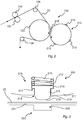
- FIG. 2 An example of a system 100 for providing a carton-based layer 20, later forming part of a packaging material 20', with a pre-laminated hole 12 is shown in Fig. 2 .
- the system 100 comprises a punching roller 110 having at least one male punch tool 210 attached to it; in Fig. 2 four male punch tools 210 are provided on the roller 110 however this number could be changed depending on the particular application.
- the roller 110 is configured to rotate against an anvil roller 120.
- the anvil roller 120 may have a rigid outer surface and one or more dies (not shown) arranged at the surface.
- a web of a carton-based layer 20 is fed through the system 100 via one or more guiding rollers 132, 134, 136, 138.
- the diameter of the anvil roller 120 may be equal, or close to the diameter of the punching roller 110.
- the part to be cut of the carton-based layer 20 should be substantially planar when the male punch tool 210 engages with the carton-based layer 20. Hence, as the punching roller 110 is rotating against the anvil roller 120 the male punch tool 210 will periodically come into contact with the carton-based layer 20, whereby a hole is cut out from the carton-based layer 20.
- the punching roller 110 may have several male punch tools 210. Hence holes having different dimensions may be cut in a continuous manner as the system 100 is operating.
- the male punch tools 210 may be distributed peripherally as well as axially on the punching roller 110; the female dies may be distributed correspondingly on the anvil roller 120.
- a punch device 200 is shown in further details in Figs. 3 and 4 .
- the punch device 200 comprises a male punch tool 210 and a female die 220; hence the system 100, configured to provide a carton-based layer 20 with a pre-laminated hole 12, comprises several punch devices 200.
- the punch device 200 may not necessarily be provided as a unit being constantly in operation; as understood from the description relating to Fig. 2 the punch devices 200 are provided when a male punch tool 210 meets a female die 220. During a revolution punch devices 200 will thereby be formed in a repetitive manner, the frequency depending on the rotational speed and the exact distribution of male punch tools 210 and female dies 220 along the periphery.
- Fig. 3 the cross-sectional view is exploded.
- the male punch tool 210 will engage with the female die 220 by a rotational movement, the respective axis of rotation being arranged at radial distances from the interface being substantially larger than the dimensions of the male punch tool 210 and/or the female die 220.
- the operational positioning of the male punch tool 210 in relation to the female die 220 is correctly represented by the setup shown in Fig. 4 , although this setup only shows full engagement between the male punch tool 210 and the female die 210.
- the male punch tool 210 comprises a body 211 having a cavity 212 accommodating a punch member 213.
- the punch member 213 is axially moveable within the cavity 212, and protrudes outside an opening 214 of the body 211.
- the opening 214 is arranged at the surface of the body 211 and provides access to the cavity 212.
- the punch member 213 is axially biased outwards, i.e. towards a maximum protruding position, by means of a spring 215.
- the punch member 213 has a flange 216 engaging with a radial stop member 217 of the body 211, the stop member 217 being arranged inside the cavity 212.
- the stop member 217 and the flange 216 ensures that the punch member 213 stays within the cavity 212.
- the punch member 213 has a round distal surface 218, whereby the dimensions of the round surface 218 correspond to the desired shape of the pre-laminated hole 12 to be formed in the carton-based layer 20.
- the diameter of the round surface 218 is slightly less than the diameter of the opening 214; hence the punch member 213 is tapered by means of a conical sidewall 219, the round surface 218 forming the distal end. As can be seen in Fig. 3 the round surface 218 is slightly convex. The convex shape of the round surface 218 will assist in proper engagement with the female die 220 during the rotational contact movement.
- the female die 220 comprises a surface 221, and a recess 222 forming a radial depression of the surface 221.
- the surface 221 may be slightly curved such as it adopts to the outer cylindrical surface of the anvil roller 120.
- the recess 222 is dimensioned such that the hole of the packaging material 20 will be formed when the punch member 213 meets with the edges of the recess 222.
- the punching operation i.e. the situation when the male punch tool 210 engages with the female die 220 to form the hole in the carton-based layer 20, is illustrated in Fig. 4 .
- the punch member 213 engages with the female die 220, such that the punch member 213 is urged radially inwards. This is possible by allowing the punch member 213 to slide within the body 211, thus overcoming the biasing force of the spring 215. Still, the spring 215 presses the punch member 213 outwards such that the punch member 213, and in particular the round distal surface 218, cuts through the carton-based layer 20 at a circumferential position indicated by reference numerals CA in Fig. 4 .
- the circumferential cut is not instant, but instead the punching operation is continuous as the male punch tool 210 rotates against the female die 220. Therefore, Fig. 4 is not fully accurate as opposite areas CA occur at the same time; in practice, these areas would occur consecutively why Fig. 4 is simplified for understanding purposes.
- the punch member 213 preferably engages with the sharp edges of the female die 220 at a circumferential position where the round distal surface 218 meets with the tapered conical wall 219, as illustrated in Fig. 4 .
- the carton-based layer 20 may run through the system 100 having a speed of several hundred meters per minute.
- the transport speed through the converting station i.e. the equipment used for providing a packaging material, is 360 m/min (i.e. 6 m/s).
- the distance between two adjacent pre-laminated holes, seen in the feeding direction, is 10 cm.
- the punching roller 110 is provided with ten male punch tools 210 distributed at equal angular distance from each other. The diameter of the punching roller 110 is thus approximately 32 cm.
- Each punch member 213 will thus hit a mating female die six times each second or 21600 times each hour. As is evident, wear of the punch member 213 is not possible to avoid.
- the inventors have realized that each time the punch member 213 engages with the female die 220 to punch the hole, some rotational forces in the plane of the surface 221 of the female die 220 is occurring. These rotational forces, mainly due to friction, will urge the punch member 213 to rotate within the body 211. During long term operation this will lead to a randomized wear of punch member 213 along its circumference, in particular at the outer radius of the distal end 218 of the punch member 213. Hence, the wear along the circumference of the distal end 218 will be quite homogenous.
- FIG. 5a An embodiment of the male punch tool 210 is shown in Fig. 5a .
- the cylindrical part 213a of the punch member 213 i.e. the longitudinal portion forming the sliding interface with the body 211, see Fig. 4
- the cylindrical part 213a of the punch member 213 is provided with two chamfers 213b spaced apart by approximately 180°.
- Each chamfer 213b fits within a corresponding chamfer 217b provided at the stop member 217, i.e. at the portion of the body 211 slidingly engaging with the punch member 213.
- the chamfers 213b, 217b ensure that the punch member 213 is no longer free to rotate within the body 211.
- a small radial gap 230 between the cylindrical part 213a of the punch member 213 and the body 211.
- This gap 230 allows for a small rotation of the punch member 213 relative the body 211, indicated by the double arrow, typically in the range of ⁇ 10° or less, such as ⁇ 5°, even more preferably ⁇ 3°. Even if such small rotation is allowed the wear will be limited to a very narrow portion of the circumference, whereby the above-described effects are still achieved.
- Fig. 5b another embodiment of a male punch tool 210 is shown.
- the shown example is very similar to the previous embodiment described with reference to Fig. 5a , however only one chamfer 213b, 217b is present in this embodiment.
- a method 300 for providing a carton-based layer 20 of a packaging material 20' is schematically shown.
- the method 300 comprises a first step 302 of arranging the carton-based layer 20 between a male punch tool 210 and a female die 220, a second step 304 of moving the male punch tool 210 and the female die 220 towards each other such that the carton-based layer 20 is clamped between the male punch tool 210 and the female die 220, and a third step 306 of decreasing the distance between the male punch tool 210 and the female die 220 such that the carton-based layer 20 is cut, whereby a punching member 213 of the male punch tool 210 is at least to some extent prevented from rotating relative a punch tool body 211 during the third step 306.
Landscapes
- Life Sciences & Earth Sciences (AREA)
- Forests & Forestry (AREA)
- Engineering & Computer Science (AREA)
- Mechanical Engineering (AREA)
- Making Paper Articles (AREA)
Abstract
A male punch tool (210) forming part of a punch device (200) for providing prelaminated holes (12) in a carton-based packaging material (20) is provided. The male punch tool (210) comprises a punch member (213) being arranged within a punch tool body (211) and allowed to move axially relative said punch tool body (211), wherein the punch member (213) is at least to some extent prevented from rotating relative the punch tool body (211).
Description
- The invention relates to a male punch tool, as well as to a punch device using such male punch tool. The invention also relates to a system for providing a carton-based layer with a pre-laminated hole, as well as a method for providing a carton-based layer with a pre-laminated hole. In addition to this the present invention also relates to a packaging material being manufactured by such method.
- Today punch devices are used to provide holes in various kinds of materials. Within the packaging industry, such punch devices can be used to provide holes in a packaging material later forming individual packages. In liquid food packaging, such holes may typically be intended to be penetrated by a straw.
- The packaging material may be a carton-based material, i.e. the packaging material comprises a core layer of carton-based material being laminated with one or more polymer layers. These types of packaging material are well known, and the hole is provided in the carton-based layer prior to lamination. In this manner the hole will be covered by the polymer layers thereby sealing the hole efficiently while still allowing for a fairly easy penetration.
- A punch device comprises a male punch tool and a female die being aligned with the male punch tool. The carton-based layer is arranged between the male punch tool and the female die. Upon operation the male punch tool is pressed towards the female die thus cutting off a piece of the carton-based layer thereby forming a hole.
- In high speed production of packaging material this punching process is implemented using a rotary system, i.e. the male punch tool is provided on a first roller while the female die is provided on a second roller. The first and second rollers are rotating against each other and they are aligned and synchronized such that the male punch tool will always hit the female die during rotation.
- Due to the rotational setup the male punch tool will roll over the female die, leading to a rather complex behavior in terms of wear of the components. Eventually there is a risk that the male punch tool will be degraded to such extent that the holes will not be punched properly, thereby leading to reduced quality of the final packages.
- For this reason there is a need for an improved punch device, increasing the life time of the male punch tool while still assuring a sufficient hole edge quality.
- It is an object of the invention to at least partly overcome one or more of the above-identified limitations of the prior art. In particular, it is an object to improve the punch device such that the male punch tool may last much longer.
- To solve these objects a male punch tool is provided. The male punch tool forms part of a punch device for providing pre-laminated holes in a carton-based packaging material. The male punch tool comprises a punch member being arranged within a punch tool body and allowed to move axially relative said punch tool body, wherein the punch member is at least to some extent prevented from rotating relative the punch tool body.
- In an embodiment the punch member is allowed to rotate relative the punch tool body by ±10° or less, such as by ±5° or less, such as by ±3° or less.
- The punch member may be provided with at least one chamfer truncating the circumference of a cylindrical portion of the punch member.
- The punch tool body may be provided with a mating chamfer to fit with the chamfer of the punch member.
- The punch member may be provided with a distal round surface.
- According to a second aspect a punch device is provided. The punch device comprises a male punch tool according to the first aspect, and a female die during use configured to be aligned with the punch member of the male punch tool.
- According to a third aspect a system for providing a carton-based layer with a pre-laminated hole is provided. The system comprises a punching roller being provided with at least one male punch tool according to the first aspect arranged at its circumference, and an anvil roller being provided with at least one female die.
- The diameter of the punching roller may be equal to the diameter of the anvil roller.
- According to a fourth aspect a method for providing a carton-based layer of a packaging material with a pre-laminated hole is provided. The method comprises i) arranging the carton-based layer between a male punch tool and a female die, ii) moving the male punch tool and the female die towards each other such that the carton-based layer is clamped between the male punch tool and the female die, and iii) decreasing the distance between the male punch tool and the female die such that the carton-based layer is cut, whereby a punching member of the male punch tool is at least to some extent prevented from rotating relative a punch tool body.
- According to a fifth aspect, a packaging material is provided. The packaging material is manufactured by the method according to the fourth aspect.
- Still other objectives, features, aspects and advantages of the invention will appear from the following detailed description as well as from the drawings.
- Embodiments of the invention will now be described, by way of example, with reference to the accompanying schematic drawings, in which
-
Fig. 1 is a perspective view of package being provided with a pre-laminated hole; -
Fig. 2 is a schematic view of a system for providing a carton-based layer with pre-laminated holes; -
Fig. 3 is a cross-sectional view of a punch device for use with the system shown inFig. 2 , wherein the punch device is arranged in an idle position; -
Fig. 4 is a cross-sectional view of the punch device shown inFig. 3 , here arranged in an active position; -
Figs. 5a-b are top views of embodiments of a male punch tool for use with the punch device ofFigs. 3 and4 ; and -
Fig. 6 is a schematic view of a method for providing a pre-laminated hole to carton-based layer of a packaging material. - Starting in
Fig. 1 aportion package 10 is shown. Thepackage 10 is formed by a carton-based packaging material 20' and it is provided with a pre-laminatedopening hole 12, as well as astraw 14 being attached to thepackage 10 by means of apouch 16. - The shown
package 10 is a brick-shaped package and contains typically 100-350 ml of liquid food product, whereby the product is accessible to a consumer by penetration of thehole 12, and insertion of thestraw 14 into thehole 12. - The
opening hole 12 is pre-laminated, i.e. thehole 12 is provided in the carton-based layer prior to lamination. - An example of a
system 100 for providing a carton-basedlayer 20, later forming part of a packaging material 20', with a pre-laminatedhole 12 is shown inFig. 2 . - The
system 100 comprises apunching roller 110 having at least onemale punch tool 210 attached to it; inFig. 2 fourmale punch tools 210 are provided on theroller 110 however this number could be changed depending on the particular application. - The
roller 110 is configured to rotate against ananvil roller 120. Theanvil roller 120 may have a rigid outer surface and one or more dies (not shown) arranged at the surface. A web of a carton-basedlayer 20 is fed through thesystem 100 via one or more guidingrollers anvil roller 120 may be equal, or close to the diameter of thepunching roller 110. Preferably the part to be cut of the carton-basedlayer 20 should be substantially planar when themale punch tool 210 engages with the carton-basedlayer 20. Hence, as thepunching roller 110 is rotating against theanvil roller 120 themale punch tool 210 will periodically come into contact with the carton-basedlayer 20, whereby a hole is cut out from the carton-basedlayer 20. - As is readily understood the
punching roller 110 may have severalmale punch tools 210. Hence holes having different dimensions may be cut in a continuous manner as thesystem 100 is operating. Themale punch tools 210 may be distributed peripherally as well as axially on thepunching roller 110; the female dies may be distributed correspondingly on theanvil roller 120. - A
punch device 200 is shown in further details inFigs. 3 and4 . Thepunch device 200 comprises amale punch tool 210 and afemale die 220; hence thesystem 100, configured to provide a carton-basedlayer 20 with apre-laminated hole 12, comprisesseveral punch devices 200. - It should be noted that the
punch device 200 may not necessarily be provided as a unit being constantly in operation; as understood from the description relating toFig. 2 thepunch devices 200 are provided when amale punch tool 210 meets afemale die 220. During arevolution punch devices 200 will thereby be formed in a repetitive manner, the frequency depending on the rotational speed and the exact distribution ofmale punch tools 210 and female dies 220 along the periphery. - In
Fig. 3 the cross-sectional view is exploded. During normal operation themale punch tool 210 will engage with the female die 220 by a rotational movement, the respective axis of rotation being arranged at radial distances from the interface being substantially larger than the dimensions of themale punch tool 210 and/or thefemale die 220. This means that the operational positioning of themale punch tool 210 in relation to thefemale die 220 is correctly represented by the setup shown inFig. 4 , although this setup only shows full engagement between themale punch tool 210 and thefemale die 210. - The
male punch tool 210 comprises abody 211 having acavity 212 accommodating apunch member 213. Thepunch member 213 is axially moveable within thecavity 212, and protrudes outside anopening 214 of thebody 211. Theopening 214 is arranged at the surface of thebody 211 and provides access to thecavity 212. - The
punch member 213 is axially biased outwards, i.e. towards a maximum protruding position, by means of aspring 215. Thepunch member 213 has aflange 216 engaging with aradial stop member 217 of thebody 211, thestop member 217 being arranged inside thecavity 212. Thestop member 217 and theflange 216 ensures that thepunch member 213 stays within thecavity 212. - The
punch member 213 has a rounddistal surface 218, whereby the dimensions of theround surface 218 correspond to the desired shape of thepre-laminated hole 12 to be formed in the carton-basedlayer 20. - The diameter of the
round surface 218 is slightly less than the diameter of theopening 214; hence thepunch member 213 is tapered by means of aconical sidewall 219, theround surface 218 forming the distal end. As can be seen inFig. 3 theround surface 218 is slightly convex. The convex shape of theround surface 218 will assist in proper engagement with thefemale die 220 during the rotational contact movement. - The female die 220 comprises a
surface 221, and arecess 222 forming a radial depression of thesurface 221. Although illustrated as planar inFig. 3 , thesurface 221 may be slightly curved such as it adopts to the outer cylindrical surface of theanvil roller 120. Also, therecess 222 is dimensioned such that the hole of thepackaging material 20 will be formed when thepunch member 213 meets with the edges of therecess 222. - The punching operation, i.e. the situation when the
male punch tool 210 engages with the female die 220 to form the hole in the carton-basedlayer 20, is illustrated inFig. 4 . - As is illustrated the
punch member 213 engages with thefemale die 220, such that thepunch member 213 is urged radially inwards. This is possible by allowing thepunch member 213 to slide within thebody 211, thus overcoming the biasing force of thespring 215. Still, thespring 215 presses thepunch member 213 outwards such that thepunch member 213, and in particular the rounddistal surface 218, cuts through the carton-basedlayer 20 at a circumferential position indicated by reference numerals CA inFig. 4 . The circumferential cut is not instant, but instead the punching operation is continuous as themale punch tool 210 rotates against thefemale die 220. Therefore,Fig. 4 is not fully accurate as opposite areas CA occur at the same time; in practice, these areas would occur consecutively whyFig. 4 is simplified for understanding purposes. - The
punch member 213 preferably engages with the sharp edges of the female die 220 at a circumferential position where the rounddistal surface 218 meets with the taperedconical wall 219, as illustrated inFig. 4 . - In high-speed manufacturing the carton-based
layer 20 may run through thesystem 100 having a speed of several hundred meters per minute. In the following an example will be given. The transport speed through the converting station, i.e. the equipment used for providing a packaging material, is 360 m/min (i.e. 6 m/s). The distance between two adjacent pre-laminated holes, seen in the feeding direction, is 10 cm. The punchingroller 110 is provided with tenmale punch tools 210 distributed at equal angular distance from each other. The diameter of the punchingroller 110 is thus approximately 32 cm. - Each
punch member 213 will thus hit a mating female die six times each second or 21600 times each hour. As is evident, wear of thepunch member 213 is not possible to avoid. - The inventors have realized that each time the
punch member 213 engages with the female die 220 to punch the hole, some rotational forces in the plane of thesurface 221 of thefemale die 220 is occurring. These rotational forces, mainly due to friction, will urge thepunch member 213 to rotate within thebody 211. During long term operation this will lead to a randomized wear ofpunch member 213 along its circumference, in particular at the outer radius of thedistal end 218 of thepunch member 213. Hence, the wear along the circumference of thedistal end 218 will be quite homogenous. - Not only have the inventors realized this, but also that this is undesired for obtaining a clean cut of the hole. Instead of having a evenly distributed wear of the
punch member 213, it would be beneficial to provide a solution ensuring that the wear will always occur at the same circumferential position of thepunch member 213. Thepunch member 213, and especially the circumference of thedistal end 218, will thereby conform to a shape and configuration ensuring a perfect engagement with the edges of thefemale die 220. - An embodiment of the
male punch tool 210 is shown inFig. 5a . Here, thecylindrical part 213a of the punch member 213 (i.e. the longitudinal portion forming the sliding interface with thebody 211, seeFig. 4 ) is provided with twochamfers 213b spaced apart by approximately 180°. Eachchamfer 213b fits within a correspondingchamfer 217b provided at thestop member 217, i.e. at the portion of thebody 211 slidingly engaging with thepunch member 213. Thechamfers punch member 213 is no longer free to rotate within thebody 211. However, as thepunch member 213 needs to move in and out from thebody 211 as explained earlier there is preferably a smallradial gap 230 between thecylindrical part 213a of thepunch member 213 and thebody 211. Thisgap 230 allows for a small rotation of thepunch member 213 relative thebody 211, indicated by the double arrow, typically in the range of ±10° or less, such as ±5°, even more preferably ±3°. Even if such small rotation is allowed the wear will be limited to a very narrow portion of the circumference, whereby the above-described effects are still achieved. - In
Fig. 5b another embodiment of amale punch tool 210 is shown. The shown example is very similar to the previous embodiment described with reference toFig. 5a , however only onechamfer - It should be noted that other embodiments are also possible, as long as the
punch member 213 is at least to some extent prevented from rotating relative thebody 211. - In
Fig. 6 amethod 300 for providing a carton-basedlayer 20 of a packaging material 20' is schematically shown. Themethod 300 comprises afirst step 302 of arranging the carton-basedlayer 20 between amale punch tool 210 and afemale die 220, asecond step 304 of moving themale punch tool 210 and the female die 220 towards each other such that the carton-basedlayer 20 is clamped between themale punch tool 210 and thefemale die 220, and athird step 306 of decreasing the distance between themale punch tool 210 and the female die 220 such that the carton-basedlayer 20 is cut, whereby a punchingmember 213 of themale punch tool 210 is at least to some extent prevented from rotating relative apunch tool body 211 during thethird step 306. - From the description above follows that, although various embodiments of the invention have been described and shown, the invention is not restricted thereto, but may also be embodied in other ways within the scope of the subject-matter defined in the following claims.
Claims (10)
- A male punch tool (210) forming part of a punch device (200) for providing pre-laminated holes (12) in a carton-based packaging material (20'), said male punch tool (210) comprising a punch member (213) being arranged within a punch tool body (211) and allowed to move axially relative said punch tool body (211), characterized in that the punch member (213) is at least to some extent prevented from rotating relative the punch tool body (211).
- The male punch tool (210) according to claim 1, wherein the punch member (213) is allowed to rotate relative the punch tool body (211) by ±10° or less, such as by ±5° or less, such as by ±3° or less.
- The male punch tool (210) according to claim 1 or 2, wherein the punch member (213) is provided with at least one chamfer (213b) truncating the circumference of a cylindrical portion (213a) of the punch member (213).
- The male punch tool (210) according to claim 3, wherein the punch tool body (211) is provided with a mating chamfer (217b) to fit with the chamfer (213b) of the punch member (213).
- The male punch tool (210) according to any one of the preceding claims, wherein the punch member (213) is provided with a distal round surface (218).
- A punch device (200), comprising a male punch tool (210) according to any one of the preceding claims, and a female die (220) during use configured to be aligned with the punch member (213) of the male punch tool (210).
- A system (100) for providing a carton-based layer (20) with a pre-laminated hole (12), comprising a punching roller (110) being provided with at least one male punch tool (210) according to any one of the preceding claims arranged at its circumference, and an anvil roller (120) being provided with at least one female die (220).
- The system (100) according to claim 7, wherein the diameter of the punching roller (110) is equal to the diameter of the anvil roller (120).
- A method for providing a carton-based layer (20) of a packaging material (20') with a pre-laminated hole (12), comprising:arranging the carton-based layer (20) between a male punch tool (210) and a female die (220),moving the male punch tool (210) and the female die (220) towards each other such that the carton-based layer (20) is clamped between the male punch tool (210) and the female die (220), anddecreasing the distance between the male punch tool (210) and the female die (220) such that the carton-based layer (20) is cut, whereby a punching member (213) of the male punch tool (210) is at least to some extent prevented from rotating relative a punch tool body (211).
- A packaging material (20') being manufactured by the method (300) according to claim 9.
Priority Applications (1)
| Application Number | Priority Date | Filing Date | Title |
|---|---|---|---|
| EP18215773.5A EP3670122A1 (en) | 2018-12-21 | 2018-12-21 | A male punch tool, and a punch device |
Applications Claiming Priority (1)
| Application Number | Priority Date | Filing Date | Title |
|---|---|---|---|
| EP18215773.5A EP3670122A1 (en) | 2018-12-21 | 2018-12-21 | A male punch tool, and a punch device |
Publications (1)
| Publication Number | Publication Date |
|---|---|
| EP3670122A1 true EP3670122A1 (en) | 2020-06-24 |
Family
ID=64949085
Family Applications (1)
| Application Number | Title | Priority Date | Filing Date |
|---|---|---|---|
| EP18215773.5A Withdrawn EP3670122A1 (en) | 2018-12-21 | 2018-12-21 | A male punch tool, and a punch device |
Country Status (1)
| Country | Link |
|---|---|
| EP (1) | EP3670122A1 (en) |
Citations (4)
| Publication number | Priority date | Publication date | Assignee | Title |
|---|---|---|---|---|
| US3064513A (en) * | 1958-05-19 | 1962-11-20 | Hickok W O Mfg Co | Sheet punching mechanism |
| US3657954A (en) * | 1970-06-15 | 1972-04-25 | Alco Machine & Tool Inc | Die cutter assembly and mounting means for punch thereof |
| US4273015A (en) * | 1979-06-04 | 1981-06-16 | Johnson Donald R | Dome head punch |
| EP1172188A1 (en) * | 2000-07-12 | 2002-01-16 | Albis | Method and apparatus for perforationg non-woven webs |
-
2018
- 2018-12-21 EP EP18215773.5A patent/EP3670122A1/en not_active Withdrawn
Patent Citations (4)
| Publication number | Priority date | Publication date | Assignee | Title |
|---|---|---|---|---|
| US3064513A (en) * | 1958-05-19 | 1962-11-20 | Hickok W O Mfg Co | Sheet punching mechanism |
| US3657954A (en) * | 1970-06-15 | 1972-04-25 | Alco Machine & Tool Inc | Die cutter assembly and mounting means for punch thereof |
| US4273015A (en) * | 1979-06-04 | 1981-06-16 | Johnson Donald R | Dome head punch |
| EP1172188A1 (en) * | 2000-07-12 | 2002-01-16 | Albis | Method and apparatus for perforationg non-woven webs |
Similar Documents
| Publication | Publication Date | Title |
|---|---|---|
| RU2471629C2 (en) | Device and method of making embossed paper or laminated metallic foil | |
| CN109153144B (en) | A cutting tool, and method of cutting material coils or sheets | |
| CA1152793A (en) | Method and apparatus for blanking, folding and inserting membrane into container covercap | |
| US4029537A (en) | Label applicator | |
| EP3323523B1 (en) | Device comprising a roller set for forming pipe ends | |
| CN104001790A (en) | Large-rotation high-speed punching progressive die of multi-column electric motor stator | |
| CA2288561A1 (en) | Rotary punching apparatus | |
| US3673834A (en) | Apparatus for and method of operating on container constructions | |
| EP1483108B1 (en) | A machine for punching blanks out of a web of corrugated cardboard and for forming folding lines in said blanks | |
| KR20130133402A (en) | Push rod for break of vehicle and the method therof | |
| CN109153143B (en) | Cutting system, and method of cutting a web or sheet of material | |
| JPS5828499A (en) | Paper web hole punch device | |
| KR101191430B1 (en) | Manufacturing apparatus for pencil core capable of sensing normal operation | |
| US10103610B2 (en) | Manufacturing method of core for rotary electric machine | |
| CN101869954A (en) | Technology for processing stop sheet | |
| CN110182426B (en) | Cold cutting machine for cutting plastic spoon packaging belt | |
| JP2018149658A (en) | Die-cut roll of rotary die cutter | |
| US20240066737A1 (en) | Cutting apparatus and method for cutting caps | |
| CN204603031U (en) | A kind of mechanical stamping mould | |
| CN204659035U (en) | Paper pressing wheel of carton making machine | |
| JP5614862B1 (en) | Winding shaft | |
| CN111169744B (en) | A packaging machine | |
| KR101191429B1 (en) | Manufacturing apparatus for pencil core | |
| CN108266494B (en) | Method for producing a transverse segment of a drive belt for a continuously variable transmission and transverse segment produced | |
| JP2681320B2 (en) | Laminated core mold equipment |
Legal Events
| Date | Code | Title | Description |
|---|---|---|---|
| PUAI | Public reference made under article 153(3) epc to a published international application that has entered the european phase |
Free format text: ORIGINAL CODE: 0009012 |
|
| STAA | Information on the status of an ep patent application or granted ep patent |
Free format text: STATUS: THE APPLICATION HAS BEEN PUBLISHED |
|
| AK | Designated contracting states |
Kind code of ref document: A1 Designated state(s): AL AT BE BG CH CY CZ DE DK EE ES FI FR GB GR HR HU IE IS IT LI LT LU LV MC MK MT NL NO PL PT RO RS SE SI SK SM TR |
|
| AX | Request for extension of the european patent |
Extension state: BA ME |
|
| STAA | Information on the status of an ep patent application or granted ep patent |
Free format text: STATUS: THE APPLICATION IS DEEMED TO BE WITHDRAWN |
|
| 18D | Application deemed to be withdrawn |
Effective date: 20210112 |