EP3670098A1 - Appareil de scellement et procédé de fonctionnement d'un appareil de scellement - Google Patents
Appareil de scellement et procédé de fonctionnement d'un appareil de scellement Download PDFInfo
- Publication number
- EP3670098A1 EP3670098A1 EP18214155.6A EP18214155A EP3670098A1 EP 3670098 A1 EP3670098 A1 EP 3670098A1 EP 18214155 A EP18214155 A EP 18214155A EP 3670098 A1 EP3670098 A1 EP 3670098A1
- Authority
- EP
- European Patent Office
- Prior art keywords
- driving
- fastening element
- control unit
- bolt
- pushing device
- Prior art date
- Legal status (The legal status is an assumption and is not a legal conclusion. Google has not performed a legal analysis and makes no representation as to the accuracy of the status listed.)
- Withdrawn
Links
Images


Classifications
-
- B—PERFORMING OPERATIONS; TRANSPORTING
- B25—HAND TOOLS; PORTABLE POWER-DRIVEN TOOLS; MANIPULATORS
- B25F—COMBINATION OR MULTI-PURPOSE TOOLS NOT OTHERWISE PROVIDED FOR; DETAILS OR COMPONENTS OF PORTABLE POWER-DRIVEN TOOLS NOT PARTICULARLY RELATED TO THE OPERATIONS PERFORMED AND NOT OTHERWISE PROVIDED FOR
- B25F5/00—Details or components of portable power-driven tools not particularly related to the operations performed and not otherwise provided for
-
- B—PERFORMING OPERATIONS; TRANSPORTING
- B25—HAND TOOLS; PORTABLE POWER-DRIVEN TOOLS; MANIPULATORS
- B25C—HAND-HELD NAILING OR STAPLING TOOLS; MANUALLY OPERATED PORTABLE STAPLING TOOLS
- B25C1/00—Hand-held nailing tools; Nail feeding devices
- B25C1/08—Hand-held nailing tools; Nail feeding devices operated by combustion pressure
-
- B—PERFORMING OPERATIONS; TRANSPORTING
- B25—HAND TOOLS; PORTABLE POWER-DRIVEN TOOLS; MANIPULATORS
- B25C—HAND-HELD NAILING OR STAPLING TOOLS; MANUALLY OPERATED PORTABLE STAPLING TOOLS
- B25C1/00—Hand-held nailing tools; Nail feeding devices
-
- B—PERFORMING OPERATIONS; TRANSPORTING
- B25—HAND TOOLS; PORTABLE POWER-DRIVEN TOOLS; MANIPULATORS
- B25C—HAND-HELD NAILING OR STAPLING TOOLS; MANUALLY OPERATED PORTABLE STAPLING TOOLS
- B25C1/00—Hand-held nailing tools; Nail feeding devices
- B25C1/06—Hand-held nailing tools; Nail feeding devices operated by electric power
-
- B—PERFORMING OPERATIONS; TRANSPORTING
- B25—HAND TOOLS; PORTABLE POWER-DRIVEN TOOLS; MANIPULATORS
- B25C—HAND-HELD NAILING OR STAPLING TOOLS; MANUALLY OPERATED PORTABLE STAPLING TOOLS
- B25C1/00—Hand-held nailing tools; Nail feeding devices
- B25C1/008—Safety devices
-
- B—PERFORMING OPERATIONS; TRANSPORTING
- B25—HAND TOOLS; PORTABLE POWER-DRIVEN TOOLS; MANIPULATORS
- B25C—HAND-HELD NAILING OR STAPLING TOOLS; MANUALLY OPERATED PORTABLE STAPLING TOOLS
- B25C1/00—Hand-held nailing tools; Nail feeding devices
- B25C1/04—Hand-held nailing tools; Nail feeding devices operated by fluid pressure, e.g. by air pressure
- B25C1/047—Mechanical details
Definitions
- the invention relates to a bolt pusher for driving fasteners in a driving direction into a surface.
- the invention further relates to a method for operating such a bolt pushing device.
- Such pin pushers usually comprise a driving piston which can be driven in a setting direction in order to push a fastening element into the ground.
- a driving piston which can be driven in a setting direction in order to push a fastening element into the ground.
- a fastening element cannot be driven into the substrate as desired, but instead is braked or deflected, for example, by harder components of the substrate. This can lead to setting failures in which the fastening element and / or the base are damaged.
- the object of the invention is to improve the setting quality of a bolt pusher.
- a bolt pusher for driving fasteners in a driving direction into a subsurface, with a driving piston which can be driven in a setting direction in order to push a fastening element into the subsurface, with a control unit which is intended to drive in the Bolt-pushing device to control, with a sensor device for detecting a parameter during the driving-in process and for transmitting a signal dependent on the detected parameter to the control unit, the control unit being provided, depending on the detected parameter, one on the fastening element within the To control the driving energy still to be transmitted.
- This makes it possible to adapt the driving energy to unforeseen circumstances such as, for example, an unusual braking of the fastening element during the driving process, so that the risk of setting failures and / or damage to the fastening element and / or the substrate is reduced.
- control unit is provided for reducing the driving energy still to be transmitted to the fastening element during the driving process.
- the control unit is preferably provided to end the transmission of driving energy to the fastening element.
- control unit is provided to redirect part of a driving energy provided for the driving process.
- An advantageous embodiment is characterized in that the detected parameter comprises a force and / or acceleration acting on the fastening element during the driving-in process, preferably transversely to the driving-in direction.
- the bolt pushing device comprises a drive which is intended to transmit driving energy to the driving piston, while the driving piston drives the fastening element into the ground.
- the drive preferably comprises an overpressure chamber and is intended to generate an overpressure in the overpressure chamber and to allow the overpressure to act on the drive piston in order to transmit driving energy to the drive piston, the overpressure chamber having a blow-off valve which can be controlled by the control unit, and wherein the Control unit is provided for controlling the driving energy still to be transmitted to the fastening element within the driving process by opening the blow-off valve during the driving process.
- the pressure chamber particularly preferably comprises a combustion chamber for a solid, liquid or gaseous fuel.
- the drive also preferably comprises an electrical energy store and a coil and is provided for electrically charging the electrical energy store, abruptly discharging it, passing a discharge current that occurs thereby through the coil and letting an electromagnetic energy released thereby act on the drive piston in order to drive energy transfer to the drive piston, the drive comprising a switch with which a current flow through the coil can be controlled, and wherein the control unit is intended to control the driving energy still to be transmitted to the fastening element within the driving process by actuating the switch during the driving process.
- the object is also achieved in a method for operating a bolt-pushing device for driving fasteners in a driving direction into a subsurface, with a driving piston which can be driven in a setting direction in order to push a fastening element into the subsurface, comprising a) acquiring a parameter during a driving-in process, and b) controlling, preferably reducing, a driving-in energy still to be transmitted to the fastening element within the driving-in process as a function of the detected parameter.
- the transmission of driving energy to the fastening element is particularly preferably ended.
- An advantageous embodiment is characterized in that part of a driving energy provided for the driving process is redirected.
- the detected parameter comprises a force and / or acceleration acting on the fastening element during the driving-in process, in particular transversely to the driving-in direction.
- a hand-held setting tool 10 for driving fasteners into a surface is shown.
- the setting tool 10 is designed as a bolt pushing device and has a receptacle 20 designed as a bolt guide, in which a fastening element 30 designed as a nail is received in order to be driven into the ground along a setting axis A (in Fig. 1 to the left).
- the setting device 10 includes a Magazine 40, in which the fasteners are received individually or in the form of a fastener strip 50 and are gradually transported into the receptacle 20.
- the magazine 40 has a spring-loaded feed element (not specified in any more detail).
- the setting tool 10 has a drive-in element 60, which comprises a piston plate 70 and a piston rod 80.
- the drive-in element 60 is provided for conveying the fastening element 30 out of the receptacle 20 along the setting axis A into the ground.
- the driving element 60 is guided with its piston plate 70 in a guide cylinder 95 along the setting axis A.
- the drive-in element 60 is in turn driven by a drive which comprises a squirrel-cage rotor 90 arranged on the piston plate 70, an excitation coil 100, a soft magnetic frame 105, a circuit 200 and a capacitor 300 with an internal resistance of 5 mOhm.
- the short-circuit rotor 90 consists of a preferably annular, particularly preferably annular element with a low electrical resistance, for example made of copper, and is fastened, for example soldered, welded, glued, clamped, to the piston plate 70 on the side of the piston plate 70 facing away from the receptacle 20 or positively connected.
- the piston plate itself is designed as a short-circuit rotor.
- the circuit 200 is intended to bring about a rapid electrical discharge of the previously charged capacitor 300 and to conduct the discharge current flowing through the excitation coil 100, which is embedded in the frame 105.
- the frame preferably has a saturation flux density of at least 1.0 T and / or an effective specific electrical conductivity of at most 10 6 S / m, so that a magnetic field generated by the excitation coil 100 is amplified by the frame 105 and eddy currents in the frame 105 are suppressed become.
- This secondary current which builds up and thus changes, in turn generates a secondary magnetic field which is opposite to the excitation magnetic field, as a result of which the short-circuit rotor 90 is one of the Excitation coil 100 experiences repulsive Lorentz force, which drives the driving element 60 towards the receptacle 20 and the fastening element 30 accommodated therein.
- the setting tool 10 further comprises a housing 110, in which the drive is accommodated, a handle 120 with an actuating element 130 designed as a trigger, an electrical energy store 140 designed as an accumulator, a control unit 150, a trigger switch 160, a pressure switch 170, an as on temperature sensor 180 arranged in the frame 105 is a means for detecting a temperature of the excitation coil 100 and electrical connecting lines 141, 161, 171, 181, 201, 301, which the control unit 150 with the electrical energy store 140, the trigger switch 160, the pressure switch 170, the temperature sensor 180, the circuit 200 or the capacitor 300 connect.
- the setting device 10 is supplied with electrical energy instead of the electrical energy store 140 or in addition to the electrical energy store 140 by means of a mains cable.
- the control unit comprises electronic components, preferably interconnected on a circuit board to form one or more control circuits, in particular one or more microprocessors.
- a pressure element (not described in more detail) actuates the pressure switch 170, which thereby transmits a pressure signal to the control unit 150 by means of the connecting line 171.
- the control unit 150 initiates a capacitor charging process in which electrical energy is conducted from the electrical energy store 140 to the control unit 150 by means of the connecting line 141 and from the control unit 150 to the capacitor 300 by means of the connecting lines 301 in order to charge the capacitor 300 .
- the control unit 150 comprises a switching converter, not designated in any more detail, which converts the electrical current from the electrical energy store 140 into a suitable charging current for the capacitor 300.
- the control unit conducts the capacitor charging process as soon as the Setting tool or when the setting tool is lifted from the ground or when a previous driving process has ended.
- the actuating element 130 When the actuating element 130 is actuated when the setting tool 10 is ready to be set, for example by pulling with the index finger of the hand which grips the handle 120, the actuating element 130 actuates the trigger switch 160, which thereby transmits a trigger signal to the control unit 150 by means of the connecting line 161. Triggered by this, the control unit 150 initiates a capacitor discharge process in which electrical energy stored in the capacitor 300 is conducted from the capacitor 300 to the excitation coil 100 by means of the circuit 200 by discharging the capacitor 300.
- the in Fig. 1 Circuit 200 schematically illustrated for this purpose comprises two discharge lines 210, 220, which connect the capacitor 300 to the excitation coil 200 and of which at least one discharge line 210 is interrupted by a normally open discharge switch 230.
- the circuit 200 forms an electrical resonant circuit with the excitation coil 100 and the capacitor 300. Swinging this oscillating circuit back and forth and / or negatively charging the capacitor 300 may have a negative effect on the efficiency of the drive, but can be prevented with the aid of a freewheeling diode 240.
- the discharge lines 210, 220 are electrically connected to an electrode 310, 320 of the capacitor 300 by means of electrical contacts 370, 380 of the capacitor 300 arranged on an end face 360 of the capacitor 300 facing the receptacle 20, for example by soldering, welding, screwing, jamming or Positive locking.
- the discharge switch 230 is preferably suitable for switching a discharge current with a high current and is designed, for example, as a thyristor.
- the discharge lines 210, 220 are at a short distance from one another so that a parasitic magnetic field induced by them is as small as possible.
- the discharge lines 210, 220 are combined to form a bus bar and are held together with a suitable means, for example a holder or a clamp.
- the freewheeling diode is electrically connected in parallel to the discharge switch. In further exemplary embodiments, not shown, no free-wheeling diode is provided in the circuit.
- the control unit 150 closes the discharge switch 230 by means of the connecting line 201, as a result of which a discharge current of the capacitor 300 flows through the excitation coil 100 at a high current.
- the rapidly increasing discharge current induces an excitation magnetic field which passes through the squirrel-cage rotor 90 and in turn induces an annular secondary electric current in the squirrel-cage rotor 90.
- This secondary current which builds up in turn generates a secondary magnetic field which is opposite to the excitation magnetic field, as a result of which the short-circuit rotor 90 experiences a Lorentz force which repels the excitation coil 100 and which drives the driving element 60 onto the receptacle 20 and the fastening element 30 accommodated therein.
- the fastening element 30 is driven into the ground by the driving-in element 60.
- the drive-in element bears against the fastening element before or at the start of the capacitor discharge.
- a braking element 85 made of a resilient and / or damping material, for example rubber, in that the driving element 60 moves with the piston plate 70 against the braking element 85 and is braked by the latter until it comes to a standstill.
- the driving-in element 60 is returned to the ready-to-set position by a resetting device, which is not described in any more detail.
- the capacitor 300 in particular its center of gravity, is arranged on the setting axis A behind the driving element 60, whereas the receptacle 20 is arranged in front of the driving element 60. With respect to the setting axis A, the capacitor 300 is thus axially offset from the driving element 60 and radially overlapping with the driving element 60. On the one hand, this allows the discharge lines 210, 220 to have a short length, which reduces their resistances and thus increases the efficiency of the drive. On the other hand, a small distance from a center of gravity of the setting device 10 to the setting axis A can be achieved. As a result, tilting moments during a recoil of the setting tool 10 during a driving-in process are low. In an embodiment not shown, the capacitor is arranged around the driving element.
- the electrodes 310, 320 are arranged on opposite sides of a carrier film 330 wound around a winding axis, for example by metallizing the carrier film 330, in particular vapor-deposited, the winding axis coinciding with the setting axis A.
- the carrier film with the electrodes is wound around the winding axis in such a way that a passage remains along the winding axis.
- the capacitor is arranged, for example, around the setting axis.
- the carrier film 330 has a film thickness of between 2.5 ⁇ m and 4.8 ⁇ m with a charging voltage of the capacitor 300 of 1500 V, and a film thickness of, for example, 9.6 ⁇ m with a charging voltage of the capacitor 300 of 3000 V.
- the carrier film is in turn composed of two or more individual films stacked one on top of the other.
- the electrodes 310, 320 have a sheet resistance of 50 ohms / ⁇ .
- a surface of the capacitor 300 has the shape of a cylinder, in particular a circular cylinder, the cylinder axis of which coincides with the setting axis A.
- the height of this cylinder in the direction of the winding axis is essentially as large as its diameter measured perpendicular to the winding axis.
- a low ratio of the height to the diameter of the cylinder results in a low internal resistance with a relatively high capacitance of the capacitor 300 and, last but not least, a compact design of the setting tool 10.
- a low internal resistance of the capacitor 300 is also achieved by a large line cross section of the electrodes 310, 320, in particular by a high layer thickness of the electrodes 310, 320, the effects of the layer thickness on a self-healing effect and / or a service life of the capacitor 300 having to be taken into account.
- the capacitor 300 is mounted in a damped manner on the remaining setting tool 10 by means of a damping element 350.
- the damping element 350 dampens movements of the capacitor 300 relative to the rest of the setting device 10 along the setting axis A.
- the damping element 350 is arranged on the end face 360 of the capacitor 300 and completely covers the end face 360.
- the electrical contacts 370, 380 protrude from the end face 360 and penetrate the damping element 350.
- the damping element 350 has an exemption, through which the electrical contacts 370, 380 protrude.
- the connecting lines 301 each have to compensate for relative movements between the capacitor 300 and the rest of the setting tool 10 a relief and / or expansion loop, not shown.
- a further damping element is arranged on the capacitor, for example on its end face facing away from the receptacle.
- the capacitor is then preferably clamped between two damping elements, that is to say the damping elements bear on the capacitor with a bias voltage.
- the connecting lines have a stiffness which decreases continuously as the distance from the capacitor increases.
- FIG. 2 is an electrical circuit diagram 400 of a setting device, not shown, for driving fasteners into a surface, not shown.
- the setting tool has a housing, not shown, a handle, not shown, with an actuating element, a receptacle, not shown, a magazine, not shown, a driving element, not shown, and a drive for the driving element.
- the drive comprises a short-circuit rotor (not shown) arranged on the driving element, an excitation coil 410, a soft-magnetic frame (not shown), a circuit 420, a capacitor 430, an electrical energy store 440 designed as an accumulator and a control unit 450 with, for example, a direct current direct current Transformer (English “DC / DC converter”) trained switching converter 451.
- the switching converter 451 has a low-voltage side U LV electrically connected to the electrical energy store 440 and a high-voltage side U HV electrically connected to the capacitor 430.
- the circuit 420 is intended to bring about a rapid electrical discharge of the previously charged capacitor 430 and to conduct the discharge current flowing thereby through the excitation coil 410.
- the circuit 420 comprises two discharge lines 421, 422, which connect the capacitor 430 to the excitation coil 420 and of which at least one discharge line 421 is interrupted by a normally open discharge switch 423.
- a free-wheeling diode 424 prevents excessive oscillation of a resonant circuit formed by the circuit 420 with the excitation coil 410 and the capacitor 430.
- the control unit 450 When the setting tool is pressed against the ground, the control unit 450 initiates a capacitor charging process in which electrical energy is conducted from the electrical energy store 440 to the switching converter 451 of the control unit 450 and from the switching converter 451 to the capacitor 430 around the capacitor 430 charge.
- the switching converter 451 converts the electrical current from the electrical energy store 440 at an electrical voltage of, for example, 22 V into a suitable charging current for the capacitor 430 at an electrical voltage of, for example, 1500 V.
- the control unit 450 initiates a capacitor discharge process in which electrical energy stored in the capacitor 430 is conducted from the capacitor 430 to the excitation coil 410 by means of the circuit 420 by discharging the capacitor 430.
- the control unit 450 closes the discharge switch 430, as a result of which a discharge current of the capacitor 430 flows through the excitation coil 410 at a high current.
- the squirrel-cage rotor (not shown) experiences a Lorentz force which repels the excitation coil 410 and which drives the drive-in element. Then the drive-in element is reset to a position ready for setting by a reset device, not shown.
- An amount of energy of the current flowing through the excitation coil 410 during the rapid discharge of the capacitor 430 is, in particular, steplessly controlled by the control unit 450 in that a charging voltage (U HV ) applied to the capacitor 430 is set during and / or at the end of the capacitor charging process and before the rapid discharge begins becomes.
- U HV charging voltage
- An electrical energy stored in the charged capacitor 430 and thus also the amount of energy of the current flowing through the excitation coil 410 during the rapid discharge of the capacitor 430 can be controlled in proportion to the charging voltage and thus by means of the charging voltage.
- the capacitor is charged during the capacitor charging process until the charging voltage U HV has reached a setpoint. Then the charging current is switched off. If the charging voltage decreases before the rapid discharge, for example due to parasitic effects, the charging current is switched on again until the charging voltage U HV has reached the setpoint again.
- the control unit 450 controls the amount of energy of the current flowing through the excitation coil 410 during the rapid discharge of the capacitor 430 as a function of a number of control variables.
- the setting device comprises a means designed as a temperature sensor 460 for detecting a temperature of the excitation coil 410 and a means for detecting a capacitance of the capacitor, which is designed, for example, as a calculation program 470 and the capacitance of the capacitor from one The course of a current and an electrical voltage of the charging current during the capacitor charging process is calculated.
- the setting device comprises a means designed as an acceleration sensor 480 for detecting a mechanical load variable of the setting device.
- the setting device comprises a means for detecting a driving depth of the fastening element into the ground, which comprises an optical, capacitive or inductive proximity sensor 490, for example, which includes a reversal position of the driving element, not shown.
- the setting device comprises a means for detecting a speed of the drive-in element, which means, designed as a first proximity sensor 500, for detecting a first point in time at which the drive-in element passes to a first position during its movement onto the fastening element, a means designed as a second proximity sensor 510 for detecting a second point in time at which the drive-in element passes to a second position during its movement onto the fastening element and has a means designed as a calculation program 520 for detecting a time difference between the first point in time and the second point in time.
- the setting device comprises an operating element 530 that can be set by a user and a means designed as a barcode reader 540 for detecting a characteristic of a fastening element to be driven.
- the control variables include the temperature detected by the temperature sensor 460 and / or the capacitance of the capacitor calculated by the calculation program 470 and / or that of the acceleration magnitude 480 of the loading device and / or the driving depth of the fastening element detected by the proximity sensor 490 and / or the speed of the driving element calculated by the calculation program 520 and / or the setting of the operating element 530 set by the user and / or that of the bar code -Readers 540 recorded characteristic of the fastener.
- the setting device furthermore comprises a sensor device designed as an acceleration sensor 550 for detecting an actual acceleration of the driving element during a driving process and for transmitting a signal dependent on the detected actual acceleration to the control unit 450.
- the control unit 450 includes a memory 560 in which a target Acceleration of the driving element is stored during a successful driving process. Once the control unit 450 makes a difference from the target acceleration and determines the actual acceleration, for example if the drive-in element is braked more than would be expected in the case of a trouble-free drive-in process, the control unit 450 stops the transmission of drive-in energy to the fastening element. This is accomplished by redirecting part of the driving energy provided for the driving process by opening the discharge switch 423. The discharge current is used, for example, to charge the capacitor 430 or the battery 440.
- the acceleration sensor detects an acceleration acting on the fastening element during the driving-in process transversely to the driving-in direction.
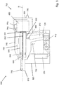
- a hand-held setting device 600 for driving fasteners into a surface, not shown is shown schematically.
- the setting tool 600 is designed as a bolt pushing device and has a housing 605 and a receptacle 610 designed as a bolt guide, in which a fastening element, not shown, is received in order to be driven into the ground along a setting axis B (in Fig. 3 to the left).
- the setting device 600 comprises a magazine 620 in which a plurality of fastening elements are accommodated and are gradually transported into the receptacle 610.
- the setting tool 600 has a drive-in element 630 designed as a piston, which comprises a piston plate 631 and a piston rod 632.
- the driving-in element 630 is provided for conveying the fastening element out of the receptacle 610 along the setting axis B into the ground.
- the driving-in element 630 is guided with its piston plate 631 in a guide cylinder 640 along the setting axis B, which has a plurality of blow-out openings 645.
- the drive-in element 630 is in turn driven by a drive 700 which has an overpressure chamber 650 designed as a combustion chamber for a fuel gas.
- the drive 700 is provided for generating an overpressure in the overpressure chamber 650, in that a fuel designed as a liquid gas is led from an fuel valve 670 through an injection line 680 into the overpressure chamber 650 by means of an injection valve 660 and ignited there. Additionally or alternatively, an overpressure is generated in the overpressure chamber 650 in that a compressor 710, which is supplied with electrical energy by an electric battery 690, conducts air into the overpressure camera 650 by means of a compressed air line 720.
- the driving element 630 transmits by means of the Piston rod 632 the driving energy on the fastener.
- This driving-in process is triggered by a user of the setting tool 600 actuating a trigger 730 in the form of a trigger.
- the setting device 600 further comprises a control unit 740, a sensor device 750 arranged in the region of the driving element 630 and / or the receptacle 610 for detecting an actual acceleration of the driving element 630 during a driving process, and a first signal line 760 for transmitting an actual acceleration detected by the dependent signal from the sensor device 750 to the control unit 740.
- the setting device 600 further comprises a blow-off valve 770 arranged on the pressure chamber for releasing an excess pressure in the pressure chamber 650 and a first control line 780 for transmitting a control signal from the control unit 740 to the blow-off valve 770.
- the control unit 740 detects an unusual acceleration or deceleration of the driving element 630 by means of a signal transmitted by the sensor device 750 via the signal line 760, the control unit 740 reduces the transmission of driving energy to the driving element 630 and thus to the fastening element. This is accomplished by the control unit 740 transmitting a control signal to the blow-off valve 770 by means of the control line 780 in order to open the blow-off valve 770. As a result, any excess pressure that may still be present in the overpressure chamber 650 is partially or completely blown off, so that the driving element is accelerated less or no longer. This reduces the risk of damage to the substrate due to excess driving energy.
- the setting device comprises an operating element 790, for example a reset button, by means of which a user can reset the control unit 740.
Landscapes
- Engineering & Computer Science (AREA)
- Mechanical Engineering (AREA)
- Chemical & Material Sciences (AREA)
- Combustion & Propulsion (AREA)
- Portable Nailing Machines And Staplers (AREA)
Priority Applications (4)
| Application Number | Priority Date | Filing Date | Title |
|---|---|---|---|
| EP18214155.6A EP3670098A1 (fr) | 2018-12-19 | 2018-12-19 | Appareil de scellement et procédé de fonctionnement d'un appareil de scellement |
| US17/416,402 US20210387317A1 (en) | 2018-12-19 | 2019-11-27 | Nail gun and method for operating a nail gun |
| EP19808602.7A EP3898120B1 (fr) | 2018-12-19 | 2019-11-27 | Appareil de scellement et procédé de fonctionnement d'un appareil de scellement |
| PCT/EP2019/082711 WO2020126366A1 (fr) | 2018-12-19 | 2019-11-27 | Pistolet goujonneur et procédé pour faire fonctionner un pistolet goujonneur |
Applications Claiming Priority (1)
| Application Number | Priority Date | Filing Date | Title |
|---|---|---|---|
| EP18214155.6A EP3670098A1 (fr) | 2018-12-19 | 2018-12-19 | Appareil de scellement et procédé de fonctionnement d'un appareil de scellement |
Publications (1)
| Publication Number | Publication Date |
|---|---|
| EP3670098A1 true EP3670098A1 (fr) | 2020-06-24 |
Family
ID=64746232
Family Applications (2)
| Application Number | Title | Priority Date | Filing Date |
|---|---|---|---|
| EP18214155.6A Withdrawn EP3670098A1 (fr) | 2018-12-19 | 2018-12-19 | Appareil de scellement et procédé de fonctionnement d'un appareil de scellement |
| EP19808602.7A Active EP3898120B1 (fr) | 2018-12-19 | 2019-11-27 | Appareil de scellement et procédé de fonctionnement d'un appareil de scellement |
Family Applications After (1)
| Application Number | Title | Priority Date | Filing Date |
|---|---|---|---|
| EP19808602.7A Active EP3898120B1 (fr) | 2018-12-19 | 2019-11-27 | Appareil de scellement et procédé de fonctionnement d'un appareil de scellement |
Country Status (3)
| Country | Link |
|---|---|
| US (1) | US20210387317A1 (fr) |
| EP (2) | EP3670098A1 (fr) |
| WO (1) | WO2020126366A1 (fr) |
Cited By (1)
| Publication number | Priority date | Publication date | Assignee | Title |
|---|---|---|---|---|
| WO2023038922A1 (fr) * | 2021-09-08 | 2023-03-16 | Illinois Tool Works Inc. | Dispositif électroportatif |
Families Citing this family (5)
| Publication number | Priority date | Publication date | Assignee | Title |
|---|---|---|---|---|
| EP3578308A1 (fr) * | 2018-06-06 | 2019-12-11 | HILTI Aktiengesellschaft | Appareil de pose |
| EP3578316A1 (fr) * | 2018-06-06 | 2019-12-11 | HILTI Aktiengesellschaft | Appareil de pose |
| EP3578305A1 (fr) * | 2018-06-06 | 2019-12-11 | HILTI Aktiengesellschaft | Appareil de pose |
| WO2023285307A1 (fr) | 2021-07-10 | 2023-01-19 | Rhefor Gbr | Outil de pose |
| WO2024118344A1 (fr) * | 2022-12-01 | 2024-06-06 | Illinois Tool Works Inc. | Mécanisme d'actionnement |
Citations (3)
| Publication number | Priority date | Publication date | Assignee | Title |
|---|---|---|---|---|
| EP1277548A1 (fr) * | 2001-07-19 | 2003-01-22 | HILTI Aktiengesellschaft | Appareil de scellement de chevilles avec réglage de la profondeur de pose |
| EP2656974A2 (fr) * | 2012-04-25 | 2013-10-30 | HILTI Aktiengesellschaft | Outil a main et procédé de fonctionnement |
| US20130319705A1 (en) * | 2012-06-05 | 2013-12-05 | Illinois Tool Works Inc. | Fastener-driving tool including a fastening result detector |
Family Cites Families (4)
| Publication number | Priority date | Publication date | Assignee | Title |
|---|---|---|---|---|
| US20130334277A1 (en) * | 2011-02-28 | 2013-12-19 | Hitachi Koki Co., Ltd. | Electric tool and method of driving electric tool |
| DE102012223011A1 (de) * | 2012-12-13 | 2014-06-18 | Hilti Aktiengesellschaft | Verfahren zum Betreiben eines handgeführten Arbeitsgeräts |
| JP6623662B2 (ja) * | 2015-10-09 | 2019-12-25 | マックス株式会社 | 打込機 |
| DE102017219712A1 (de) * | 2017-11-07 | 2019-05-09 | Robert Bosch Gmbh | Gerät mit Rucksteuerung |
-
2018
- 2018-12-19 EP EP18214155.6A patent/EP3670098A1/fr not_active Withdrawn
-
2019
- 2019-11-27 EP EP19808602.7A patent/EP3898120B1/fr active Active
- 2019-11-27 US US17/416,402 patent/US20210387317A1/en active Pending
- 2019-11-27 WO PCT/EP2019/082711 patent/WO2020126366A1/fr unknown
Patent Citations (3)
| Publication number | Priority date | Publication date | Assignee | Title |
|---|---|---|---|---|
| EP1277548A1 (fr) * | 2001-07-19 | 2003-01-22 | HILTI Aktiengesellschaft | Appareil de scellement de chevilles avec réglage de la profondeur de pose |
| EP2656974A2 (fr) * | 2012-04-25 | 2013-10-30 | HILTI Aktiengesellschaft | Outil a main et procédé de fonctionnement |
| US20130319705A1 (en) * | 2012-06-05 | 2013-12-05 | Illinois Tool Works Inc. | Fastener-driving tool including a fastening result detector |
Cited By (1)
| Publication number | Priority date | Publication date | Assignee | Title |
|---|---|---|---|---|
| WO2023038922A1 (fr) * | 2021-09-08 | 2023-03-16 | Illinois Tool Works Inc. | Dispositif électroportatif |
Also Published As
| Publication number | Publication date |
|---|---|
| WO2020126366A1 (fr) | 2020-06-25 |
| EP3898120B1 (fr) | 2023-01-04 |
| US20210387317A1 (en) | 2021-12-16 |
| EP3898120A1 (fr) | 2021-10-27 |
Similar Documents
| Publication | Publication Date | Title |
|---|---|---|
| EP3898120B1 (fr) | Appareil de scellement et procédé de fonctionnement d'un appareil de scellement | |
| EP3801990B1 (fr) | Appareil de pose | |
| EP3801998B1 (fr) | Appareil de fixation | |
| WO2019233845A1 (fr) | Appareil de pose | |
| EP3801991A1 (fr) | Appareil de pose | |
| EP3801994A1 (fr) | Appareil de pose | |
| EP3801997A1 (fr) | Appareil de pose | |
| EP3801989B1 (fr) | Appareil de pose | |
| EP3801993B1 (fr) | Appareil de pose | |
| EP3801996A1 (fr) | Appareil de pose | |
| EP3993954A1 (fr) | Appareil de travail | |
| EP3801992A1 (fr) | Appareil de pose | |
| EP4076855B1 (fr) | Appareil de travail | |
| EP4076850B1 (fr) | Appareil de travail | |
| WO2021122294A1 (fr) | Outil de travail | |
| EP4076854B1 (fr) | Appareil de travail | |
| EP3578310A1 (fr) | Outil de fixation | |
| EP3578314A1 (fr) | Appareil de pose |
Legal Events
| Date | Code | Title | Description |
|---|---|---|---|
| STAA | Information on the status of an ep patent application or granted ep patent |
Free format text: STATUS: UNKNOWN |
|
| PUAI | Public reference made under article 153(3) epc to a published international application that has entered the european phase |
Free format text: ORIGINAL CODE: 0009012 |
|
| STAA | Information on the status of an ep patent application or granted ep patent |
Free format text: STATUS: THE APPLICATION HAS BEEN PUBLISHED |
|
| AK | Designated contracting states |
Kind code of ref document: A1 Designated state(s): AL AT BE BG CH CY CZ DE DK EE ES FI FR GB GR HR HU IE IS IT LI LT LU LV MC MK MT NL NO PL PT RO RS SE SI SK SM TR |
|
| AX | Request for extension of the european patent |
Extension state: BA ME |
|
| STAA | Information on the status of an ep patent application or granted ep patent |
Free format text: STATUS: THE APPLICATION IS DEEMED TO BE WITHDRAWN |
|
| 18D | Application deemed to be withdrawn |
Effective date: 20210112 |