EP3670000B1 - Attachment system for mounting a dispensing pump to a bottle and associated fluid product bottle - Google Patents
Attachment system for mounting a dispensing pump to a bottle and associated fluid product bottle Download PDFInfo
- Publication number
- EP3670000B1 EP3670000B1 EP19214620.7A EP19214620A EP3670000B1 EP 3670000 B1 EP3670000 B1 EP 3670000B1 EP 19214620 A EP19214620 A EP 19214620A EP 3670000 B1 EP3670000 B1 EP 3670000B1
- Authority
- EP
- European Patent Office
- Prior art keywords
- collar
- travel
- attachment system
- sleeve
- hinge collar
- Prior art date
- Legal status (The legal status is an assumption and is not a legal conclusion. Google has not performed a legal analysis and makes no representation as to the accuracy of the status listed.)
- Active
Links
- 239000012530 fluid Substances 0.000 title claims description 24
- 239000002537 cosmetic Substances 0.000 description 2
- 230000002093 peripheral effect Effects 0.000 description 2
- 239000000825 pharmaceutical preparation Substances 0.000 description 2
- 229940127557 pharmaceutical product Drugs 0.000 description 2
- 238000004064 recycling Methods 0.000 description 2
- 239000011324 bead Substances 0.000 description 1
- 230000000903 blocking effect Effects 0.000 description 1
- 230000000295 complement effect Effects 0.000 description 1
- 238000006073 displacement reaction Methods 0.000 description 1
- 239000007788 liquid Substances 0.000 description 1
- 238000012423 maintenance Methods 0.000 description 1
- 235000011837 pasties Nutrition 0.000 description 1
- 230000000717 retained effect Effects 0.000 description 1
- 238000007789 sealing Methods 0.000 description 1
- 239000007921 spray Substances 0.000 description 1
Images


Classifications
-
- B—PERFORMING OPERATIONS; TRANSPORTING
- B05—SPRAYING OR ATOMISING IN GENERAL; APPLYING FLUENT MATERIALS TO SURFACES, IN GENERAL
- B05B—SPRAYING APPARATUS; ATOMISING APPARATUS; NOZZLES
- B05B11/00—Single-unit hand-held apparatus in which flow of contents is produced by the muscular force of the operator at the moment of use
- B05B11/0005—Components or details
- B05B11/0008—Sealing or attachment arrangements between sprayer and container
-
- B—PERFORMING OPERATIONS; TRANSPORTING
- B05—SPRAYING OR ATOMISING IN GENERAL; APPLYING FLUENT MATERIALS TO SURFACES, IN GENERAL
- B05B—SPRAYING APPARATUS; ATOMISING APPARATUS; NOZZLES
- B05B11/00—Single-unit hand-held apparatus in which flow of contents is produced by the muscular force of the operator at the moment of use
- B05B11/01—Single-unit hand-held apparatus in which flow of contents is produced by the muscular force of the operator at the moment of use characterised by the means producing the flow
- B05B11/10—Pump arrangements for transferring the contents from the container to a pump chamber by a sucking effect and forcing the contents out through the dispensing nozzle
- B05B11/1042—Components or details
- B05B11/1043—Sealing or attachment arrangements between pump and container
- B05B11/1045—Sealing or attachment arrangements between pump and container the pump being preassembled as an independent unit before being mounted on the container
-
- B—PERFORMING OPERATIONS; TRANSPORTING
- B05—SPRAYING OR ATOMISING IN GENERAL; APPLYING FLUENT MATERIALS TO SURFACES, IN GENERAL
- B05B—SPRAYING APPARATUS; ATOMISING APPARATUS; NOZZLES
- B05B11/00—Single-unit hand-held apparatus in which flow of contents is produced by the muscular force of the operator at the moment of use
- B05B11/01—Single-unit hand-held apparatus in which flow of contents is produced by the muscular force of the operator at the moment of use characterised by the means producing the flow
- B05B11/10—Pump arrangements for transferring the contents from the container to a pump chamber by a sucking effect and forcing the contents out through the dispensing nozzle
- B05B11/1042—Components or details
- B05B11/1043—Sealing or attachment arrangements between pump and container
- B05B11/1049—Attachment arrangements comprising a deformable or resilient ferrule clamped or locked onto the neck of the container by displacing, e.g. sliding, a sleeve surrounding the ferrule
Definitions
- the invention relates to a system for fixing a fluid dispenser pump.
- the invention also relates to the bottle of associated fluid product.
- the fluid product can be a cosmetic product, a pharmaceutical product or any other product.
- Bottles of fluid product conventionally comprise a reservoir for the fluid product surmounted in its upper part by a rigid neck defining an opening into which the fluid product dispensing system is inserted.
- the dispensing system comprises a pump which can be actuated by a user by means of a push button, which makes it possible to dispense a dose of the fluid product, in particular in the form of a spray.
- the dispensing system further comprises fastening and sealing means which allow it to be held at the level of the neck and, if necessary, to isolate the reservoir from the external environment.
- fastening means allowing permanent fastening of the dispensing system at the level of the neck, fastening means requiring a threshold force to unlock said fastening means and removable fastening means.
- the use of one configuration rather than another depends on the problem addressed.
- the fastening system is provided with a sleeve, a collar mounted around the sleeve and able to move partially according to a helical movement around said sleeve by the actuation of a hoop.
- the sleeve is configured so that the unscrewing the fastening system requires the application of a threshold force by the user, thanks to the presence of lugs.
- This fixing system is characterized in that said start and end of stroke positions are located so that the joint collar is able to pass from the high position of dismantling to the low position of use by translation.
- the idea of the invention is to allow the reassembly of the pump by a simple gesture, namely, a translation while retaining the advantages of a fixing system comprising a sleeve, an articulation collar and a hoop.
- the start and end of travel positions are advantageously located in axial extension of each other so that the joint collar is able to slide from the end of travel housing towards the start housing stroke by translation and that the reassembly of the pump is also possible by simple support of the user.
- the system is again in the starting position of the race and the same disassembly/reassembly cycle can be started again.
- the invention further relates to a dispensing bottle for a fluid product, comprising a reservoir for the fluid product, said reservoir being provided with a neck defining an opening for said reservoir, said bottle further comprising a dispensing pump and a system fixing as described above, said system making it possible to fix said pump on said neck.
- said neck of the dispensing bottle is provided with an anti-rotation system of said fixing system.
- the invention relates to a dispensing bottle for a fluid product comprising a reservoir 3 and a dispensing head 1 for the fluid product contained in the reservoir 3.
- the fluid product can be a cosmetic product, a pharmaceutical product or any other product which can usefully be stored in a bottle.
- the fluid can be directly in contact with the reservoir 3. That said, the fluid can be included in a flexible pocket located within said reservoir 3 so that it is not in contact with the reservoir 3 but with said flexible pocket .
- Reservoir 3 can be either rigid or deformable. This being so, the reservoir 3 comprises, at an upper part, a neck 4 and an opening 5 formed in said neck 4.
- the neck 4 is preferably rigid. It forms a groove 7 with the reservoir 3 and a peripheral edge 6 surmounting said groove 7.
- the dispensing head 1 is equipped with a pump 2 for dispensing the fluid product contained in the reservoir 3.
- the dispensed fluid is in particular liquid, viscous or pasty.
- the dispensing pump 2 comprises a body extending along a central longitudinal axis X corresponding to a median axis of the bottle.
- the body is of tubular shape, in particular of revolution.
- the dispensing pump 2 is held stationary at the level of the neck 4 by means of a fastening system according to the invention. This being the case, the distribution pump 2 can be removed from this location by means of said fixing system, for example for the purpose of filling the reservoir 3. In other words, the distribution pump 2 is removable.
- the fixing system comprises a fixing sleeve 10, an articulation collar 25 and a hoop 30.
- the articulation collar 25 and the sleeve 10 are mounted so as to move relative to each other between a start of stroke position P I (illustrated in figure 1 ) and a limit position P F (shown in picture 3 ).
- the kinematics of movement of said joint collar 25 relative to said sleeve 10 will be better described below.
- the hoop 30 is itself configured to actuate a displacement of said articulation collar 25 relative to said sleeve 10. It also has a decorative function, its outer surface being visible to the user.
- the sleeve 10 is of generally cylindrical shape and extends along the axis X.
- the sleeve 10 is hollow. It delimits an empty interior volume essentially serving to accommodate the dispensing pump 2. However, the pump 2 extends axially beyond the ends of the sleeve 10.
- the sleeve 10 is provided with means 11 for attaching the dispensing pump 2.
- the hooking means 11 make it possible to keep the pump 2 immobile at the level of the neck 4, for example in an extended way thanks to a seal 9.
- the sleeve 10 comprises a skirt 12 configured to come into engagement with the neck 4.
- the skirt 12 comprises a flat portion 14 capable of coming around the peripheral edge 6, possibly by tightening.
- the skirt 12 further comprises fastening means 15 to the neck 4 extending in the extension of the flat portion 14.
- the fixing means 15 consist of flexible lugs able to perform movements independently of each other.
- the flexible tabs 15 are regularly spaced from each other over the entire periphery of the skirt 12, that is to say that the flexible tabs are separated from each other by a constant distance.
- the flexible tabs 15 are connected to the flat portion 14 by means of a hinge portion 15a. They alternately adopt a release position in which they are free, that is to say they are not in engagement with the neck 4 and an engagement position in which they are in engagement with said neck 4.
- flexible tabs 15 have, on their internal faces, that is to say on their faces facing the neck 4, a shape substantially complementary to the shape of the groove 7. In the configuration illustrated in figure 1 , the flexible lugs 15 are in the released position, that is to say they are not engaged in the groove 7.
- the sleeve 10 further comprises a guide collar 16 whose main function is to guide the joint collar 25 in its movements.
- the articulation collar 25 is more precisely mounted mobile around the guide collar 16. In other words, it is capable of moving relative to said guide collar 16.
- Said guide collar 16 comprises means for guiding said collar hinge 25, which will be described in more detail below.
- the articulation collar 25, for its part, comprises means for moving along said guide means of said guide collar 16.
- the guide collar 16 and the articulation collar 25 therefore form a movable mechanical assembly.
- the guide collar 16 is located in the longitudinal extension of the skirt 12.
- the hoop 30 is generally cylindrical in shape. As mentioned above, it is configured to actuate the movement of said joint collar 25. In this respect, it comprises an inner wall 31 on which ribs 32 are angularly distributed. The ribs are more precisely located on an upper portion of the hoop 30, along which the joint collar 25 is able to move. The ribs 32 make it possible to secure the hoop 30 and the articulation collar 25. In this case, in the embodiment illustrated in figures 1 to 3 , it can be seen that the ribs 32 (visible on the figure 1 ) are embedded in an outer wall 29 of the articulation collar 25, which allows the tightening and therefore the securing of the hoop 30 around the articulation collar 25. This thus makes it possible to make the drive of the articulation collar 25 more reliable. by fret 30.
- hoop 30 is configured to perform a translational movement. This translation movement of the hoop 30 is made possible by the configuration of the hinge collar 25 relative to the skirt 12.
- the outer wall 29 of the hinge collar 25 is here substantially aligned with the flat portion 14 of the skirt 12 so that hoop 30 is always held in abutment on outer wall 29 and on flat portion 14.
- hoop 30 is thus capable of moving longitudinally, in particular between a proximal position and a distal position relative to the sleeve 10 by driving said articulation collar 25.
- hoop 30 is adapted to actuate the movement of joint collar 25 between a high position P H for dismantling and a low position P B for use.
- the hoop 30 must move towards its distal position.
- the hoop 30 must move towards its proximal position. It should be noted that in the configuration illustrated in the figure 1 , the joint collar 25 is neither in the high position P H for dismantling nor in the low position P B for use but in a position before initial assembly.
- the joint collar 25 is in the low position P B of use.
- the fixing system is held rigidly around the collar 4 and the bottle is ready to be used.
- the hoop 30 being located in the proximal position and therefore completely lowered, its inner wall 31 exerts a radial pressure on the fixing means 15 which are in the engagement position.
- the fixing means 15 are engaged with the neck 4.
- the outer faces of the flexible tabs 15 are in vertical alignment with the flat portion 14, while their inner faces are completely engaged in the groove 7 of the collar.
- the groove 7 includes a recess 8.
- the recess 8 forms an anti-rotation system of the fixing system in which one or more lugs 15 can be housed.
- the joint collar 25 is in the high dismantling position P H.
- the fastening system is no longer in engagement with the collar 4.
- the user may possibly fill the reservoir 3 again if the fluid product used lends itself to such manipulation.
- the hoop 30 being located in the distal position, and therefore fully raised, the inner wall 31 no longer exerts pressure on the fixing means 15 which releases said fixing means 15.
- the flexible tabs 15 are in the release position. In other words, the flexible tabs 15 are free.
- the figure 1 illustrates the bottle before initial fixing of the dispensing head 1 on the reservoir. Such an operation takes place, for example, at the manufacturer in charge of the initial filling of the bottle.
- the sleeve 10 is mounted on the neck 4, the flexible tabs 15 being free.
- the joint collar 25 is in the low position P B of use.
- the hoop 30 is in a retracted position corresponding to the high position P H for dismantling the picture 3 but without the hoop already being tightly mounted on said hinge collar 25, thus allowing the flexible tabs 15 to be free and the dispensing head 1 to be mounted on the reservoir.
- the hoop 30 is lowered by force according to a translational movement and the dispensing head passes into the configuration of the picture 2 .
- This translation movement is facilitated by the ribs 32 dedicated to guiding the joint collar 25.
- the joint collar 25 when the joint collar 25 is located in the high dismantling position P H ( fig. 3 ), it is in abutment with the sleeve 10 at an end position P F .
- the joint collar 25 when the joint collar 25 is located in the low position P B of use ( fig. 2 ), it is in abutment with said sleeve 10 at the start of stroke position P I .
- the devices of the prior art are configured so that the user is obliged to unscrew the joint collar 25 from the sleeve 10. The subsequent reassembly, if permitted, is then carried out by screwing.
- joint collar 25 and the sleeve 10 can be in abutment, without necessarily that one of said parts is embedded in the other part. In other words, there may be play between joint collar 25 and sleeve 10.
- the start and end positions P I , P F are located so that the articulation collar 25 is able to pass from the high position P H of dismantling (as illustrated in figure 2 ) to the low operating position P B (as illustrated in picture 3 ) by translation.
- the fastening system can be dismantled, for example, by unscrewing, said fastening system can be reassembled on the neck 4 of the tank 3 by a simple translational movement and therefore a simple support from the user. No screwing is therefore necessary for reassembly.
- the sleeve 10 advantageously comprises first means for guiding, in translation, said articulation collar 25 of the high position P H for disassembly to the low position P B for use.
- the first means for guiding in translation are located on the guide collar 16. They extend along the start of stroke position P I and the end of stroke position P F . It is preferable that these first means for guiding in translation be at least two in number. This makes it possible to make the movement of the articulation collar 25 relative to the sleeve 10 more reliable.
- these first means for guiding in translation comprise a start-of-stroke housing 19 located at the start-of-stroke position P I and an end-of-stroke housing 20 located at the end-of-stroke position P F .
- the start and end of travel housings 19, 20 form, in combination, a groove or even a notch having a grip of substantially rectangular shape on the guide collar 16.
- the groove extends longitudinally over the entire height of the guide collar 16, that is to say between an upper free edge of the guide collar 16 and the skirt 12.
- the height of the guide collar 16 therefore corresponds substantially to the longitudinal distance that the articulation collar 25 can cover during its travel from the high position P H for disassembly to the low position P B for use.
- the skirt 12 forms an outer bearing surface 13 on which rests a lower edge of the joint collar 25 when it is in the low position P B of use.
- the outer bearing surface 13 contributes to the blocking in translation of the articulation collar 25.
- the limit switch housing 20 comprises a flat end 20a forming a discontinuity at the level of the upper free edge of the guide collar 16. This in particular makes it possible to predispose the articulation collar 25 with respect to the guide collar 16 and the initial mounting of the articulation collar on the sleeve 10.
- Each of said first means for guiding in translation further comprises a first locking means 18.
- the start and end of travel housings 19, 20 are connected via said first locking means 18. Any translational movement of the collar d articulation 25 from the high position P H for disassembly to the low position P B for use implies that said articulation collar 25 is able to pass over said first locking means 18.
- Said first locking means 18 is configured to allow said joint collar 25 to move in translation from the high position P H for dismantling to the low position P B for use by translation by application of a threshold pressure.
- said first locking means 18 forms a boss, that is to say an extra thickness between said start and end of travel housings 19, 20.
- the first locking means 18 comprises a retaining portion 18a.
- Said retaining portion 18a forms a bearing surface for the articulation collar 25 when the latter is in the high dismantling position P H.
- the retaining portion 18a is inclined with respect to a bottom of the groove. More precisely, it makes an obtuse angle with the limit switch housing 20. Being thus configured, the retaining portion 18a allows both the maintenance of the articulation collar 25 and its sliding along the groove, and therefore from the end-of-travel position P F towards the start-of-travel position P I .
- said first locking means 18 comprises a locking flange 18b.
- This locking rim 18b extends from the bottom of the groove along a plane transverse to the axis direction X. More precisely, it forms a right angle with the start of travel housing 19.
- the locking rim 18b therefore forms an upper stop for said joint collar 25 in the low position P B of use.
- the first locking means 18 comprises a ridge 18c by which the retaining portion 18a is connected to the locking flange 18b.
- the edge 18c can be likened to a top of the boss 18.
- the ridge 18c has a height, referred to as the projection height, substantially equal to the depth of the groove relative to an outer periphery of the guide collar 16. This is not mandatory.
- the projection height defines the pressure which must be applied to the joint collar 25 to cross the first locking means 18 and reach the start-of-stroke housing 19. It is understood that the higher the projection height, the greater the pressure at exercise is important.
- the joint collar 25 is in the form of a hollow cylinder. This is not limiting in the context of the present invention. In any case, it is necessary that the shape of the joint collar 25 conforms to that of the sleeve 10 since the joint collar 25 is movably mounted around said sleeve 10.
- the joint collar 25 comprises a protuberance 26 able to move along said first translational guide means. Protrusion 26 extends radially from an inner wall of joint collar 25. It has a generally rectangular shape, although this is not required. This shape is adapted to that of the guide means along which it must move. More specifically, longitudinally oriented lateral sides of the protuberance 26 slide against longitudinally oriented lateral sides of the groove formed by the housings 19, 20.
- the outer collar 25 also has an inner bead 27 able to bear against an extra thickness 17 of an upper edge of the sleeve 10.
- the joint collar 25 is in the high dismantling position P H , it is configured to remain at the level of the end-of-travel position 20, so that the articulation collar 25 is maintained at the level of the sleeve 10.
- a lower edge said articulation collar is capable of coming to rest on the outer bearing surface 13.
- the sleeve 10 may comprise, in addition to the first means for guiding in translation, second means for guiding the articulation collar 25. These second guide means allow the articulation collar 25 to be screwed and unscrewed from said sleeve 10.
- these second guiding means are positioned on the guide collar 16. Preferably, they extend between said start and end positions P I , P F . Each has at its ends a start of travel housing 19 and an end of travel housing 20. It should be understood that if there are two second guide means this implies that there are four housings in total since each of the second guide means comprises a start of race housing 19 and an end of race housing 20, in the longitudinal sequence of one another, two by two.
- the fastening system according to the invention is particularly ingenious. Indeed, the start and end of travel housings 19, 20 referred to in the second guide means are the same housings which form the first translation guide means, in this case the groove.
- the architecture of the guide means is thus optimized to allow both the reassembly of the fastening system by simple pressing of the user but also the screwing and unscrewing of said system.
- the second guide means are configured so that the articulation collar 25 is able to perform a rotational and translational movement, in particular screwing around said sleeve 10 in order to dismantle the fastening system.
- each of the second guide means advantageously comprises a helical section 21.
- Each helical section 21 comprises a first end 22 comprising the start-of-travel housing 19 and a second end 23 comprising the end-of-travel housing 20.
- the number of second guide means is preferably at least equal to two. That said, this number is not limiting.
- second guide means each comprising a helical section 21 1 , ..., 21 i , 21 i+1 ,..., 21 n , i being a natural number with i ⁇ 1 and i+1 ⁇ n.
- Each of the helical sections 21 1 , ..., 21 i , 21 i+1 ,..., 21 n , i being a natural integer with i ⁇ n respectively comprises a first end 22 1 , ..., 22 i , 22 i+1 ,..., 22 n and a second end 23 1 , ..., 23 i , 23 i+1 ,..., 23 n .
- Said second guide means are configured so that the first end 22 1 of a first helical section 21 1 is located opposite the second end 23 n of a last helical section 21 n and that each of the other first ends 22 i+1 of the helical sections is located opposite the other second ends 23 i of the helical sections which precede them.
- the first ends 22 1 , ..., 22 i , 22 i+1 ,..., 22 n form with the second ends 23 1 , ..., 23 i , 23 i+1 ,... , 23 n the housings of the first means for guiding in translation, in this case grooves, which makes the fastening system of the invention a system that is both practical and ingenious.
- n is equal to one
- the ends of the helical section 21 also form the start and end housings. end of race 19, 20 of the groove allowing the joint collar 25 to pass from the high position P H for dismantling to the low position P B for use.
- first helical section 21 1 makes a half turn of the guide collar 16 and the second helical section 21 2 makes a remaining half turn of the guide collar 16.
- first end 22 1 of the first helical section 21 1 is located opposite the second end 23 2 of the second helical section 21 2 and the first end 22 2 of the second helical section 22 5 is located opposite -à-vis the second end 23 1 of the first helical section.
- the first end 22 1 and the second end 23 2 form the housings of a first means of guiding in translation, while the first end 22 2 and the second end 23 1 form the housings of a second means of guiding in translation.
- each second guide means comprises second locking means 19b, 20b separating the start and end of travel housings 19, 20 of said helical section 21.
- Said second locking means 19b, 20b consist of bosses or extra thicknesses, one of which projection height determines the pressure which must be applied so that the articulation collar 25, in particular the protuberance 26 leaves the start or end of stroke housing 19, 20 to reach the helical section 21.
- the second locking means 19b, 20b are configured to allow rotational movement of the joint collar 25 around said sleeve 10 by applying a threshold pressure.
- the extra thickness 20b forms a firm abutment (as illustrated in the figure 4b ). In other words, it prevents the screwing of the joint collar 25 around the sleeve 10, even if high pressure is exerted. In such a configuration, the protrusion 26 cannot leave the end-of-travel housing 20 to reach the helical section 21. It is thus understood that only the translation of the protrusion 26 from the end-of-travel housing 20 towards the start of race 19 is authorized to reach the low position P B of use.
- the extra thickness 20b is configured so that the unscrewing of the articulation collar 25 around the sleeve 10 is authorized by application of a threshold pressure (as illustrated on the figure 4b ).
- the protrusion 26 moves from the end-of-travel housing 20 towards the start-of-travel housing 19 passing over the extra thickness 20b, along the helical section 21 and over the extra thickness 19b, in this order it is of a screw.
- the joint collar 25 therefore passes from the high position P H for dismantling to the low position for use P B by screwing.
Description
L'invention concerne un système de fixation d'une pompe de distribution de produit fluide. L'invention concerne également le flacon de produit fluide associé.The invention relates to a system for fixing a fluid dispenser pump. The invention also relates to the bottle of associated fluid product.
Dans le cadre de l'invention, le produit fluide peut être un produit cosmétique, un produit pharmaceutique ou tout autre produit.In the context of the invention, the fluid product can be a cosmetic product, a pharmaceutical product or any other product.
Les flacons de produit fluide comprennent classiquement un réservoir pour le produit fluide surmonté dans sa partie supérieure d'un col rigide délimitant une ouverture dans laquelle est inséré le système de distribution du produit fluide.Bottles of fluid product conventionally comprise a reservoir for the fluid product surmounted in its upper part by a rigid neck defining an opening into which the fluid product dispensing system is inserted.
Le système de distribution comprend une pompe qui peut être actionnée par un utilisateur au moyen d'un bouton poussoir, ce qui permet de distribuer une dose du produit fluide, notamment sous forme de spray.The dispensing system comprises a pump which can be actuated by a user by means of a push button, which makes it possible to dispense a dose of the fluid product, in particular in the form of a spray.
Le système de distribution comprend en outre des moyens de fixation et d'étanchéité qui permettent son maintien au niveau du col et au besoin d'isoler le réservoir de l'environnement extérieur. Parmi les différentes configurations existantes, on distingue les moyens de fixation permettant une fixation définitive du système de distribution au niveau du col, des moyens de fixation nécessitant un effort seuil pour déverrouiller lesdits moyens de fixation et des moyens de fixation amovibles. L'utilisation d'une configuration plutôt qu'une autre dépend de la problématique adressée.The dispensing system further comprises fastening and sealing means which allow it to be held at the level of the neck and, if necessary, to isolate the reservoir from the external environment. Among the various existing configurations, a distinction is made between fastening means allowing permanent fastening of the dispensing system at the level of the neck, fastening means requiring a threshold force to unlock said fastening means and removable fastening means. The use of one configuration rather than another depends on the problem addressed.
On connait de l'art antérieur un système de fixation d'une pompe sur un col d'un réservoir configuré pour faciliter le recyclage du système une fois démonté. Le système de fixation est muni d'un manchon, un collet monté autour du manchon et apte à se déplacer partiellement selon un mouvement hélicoïdal autour dudit manchon par l'actionnement d'une frette. Le manchon est configuré de sorte que le dévissage du système de fixation requiert l'application d'un effort seuil par l'utilisateur, grâce à la présence d'ergots. Une fois qu'une position de démontage est atteinte, le collet reste en position de démontage sur le manchon tandis que la pompe peut être retirée, ce qui permet soit un recyclage du flacon, débarrassé de la pompe, soit à l'utilisateur de remplir le réservoir de nouveau. Pour remonter la pompe, c'est-à-dire la replacer en position d'utilisation, l'utilisateur doit nécessairement revisser le collet. Cependant, les ergots permettant de calibrer l'effort à fournir pour le dévissage sont configurés de telle sorte que le remontage est quasi impossible ou très difficile. En outre, même si l'utilisateur arrivait à replacer la pompe, cela devrait passer, comme indiqué, par un mouvement de vissage. On connaît aussi de l'art antérieur le document
La présente invention fournit un système de fixation qui permet, après remplissage du réservoir, de remonter la pompe par vissage mais également et surtout par simple appui sur la frette et propose à cet égard un système de fixation d'une pompe de distribution sur le col d'un réservoir contenant du produit fluide, ledit système comprenant :
- un manchon comprenant des moyens de fixation sur ledit col et des moyens d'accroche de la pompe ;
- un collet d'articulation, ledit collet d'articulation et le manchon étant montés mobiles l'un par rapport à l'autre entre une position de fin de course et une position de début de course;
- une frette configurée pour déplacer ledit collet d'articulation entre une position haute de démontage, dans laquelle lesdits moyens de fixation sont libres, et une position basse d'utilisation, dans laquelle lesdits moyens de fixation sont en prise autour dudit col.
- a sleeve comprising means for fixing on said neck and means for attaching the pump;
- an articulation collar, said articulation collar and the sleeve being mounted so as to move relative to each other between an end-of-travel position and a start-of-travel position;
- a hoop configured to move said articulation collar between a high disassembly position, in which said fastening means are free, and a low use position, in which said fastening means are engaged around said collar.
Ce système de fixation est caractérisé en ce que lesdites positions de début et de fin de course sont situées de sorte que le collet d'articulation soit apte à passer de la position haute de démontage vers la position basse d'utilisation par translation.This fixing system is characterized in that said start and end of stroke positions are located so that the joint collar is able to pass from the high position of dismantling to the low position of use by translation.
L'idée de l'invention est de permettre le remontage de la pompe par une gestuelle simple, à savoir, une translation tout en conservant les avantages d'un système de fixation comprenant un manchon, un collet d'articulation et une frette. À cet égard, les positions de début et de fin de course sont avantageusement situées dans le prolongement axial l'une de l'autre de sorte que le collet d'articulation soit capable de glisser depuis le logement de fin de course vers le logement de début de course par translation et que le remontage de la pompe soit aussi possible par simple appui de l'utilisateur. En outre, une fois remis en place, le système est à nouveau en position de début de course et un même cycle de démontage/remontage peut être recommencé.The idea of the invention is to allow the reassembly of the pump by a simple gesture, namely, a translation while retaining the advantages of a fixing system comprising a sleeve, an articulation collar and a hoop. To In this regard, the start and end of travel positions are advantageously located in axial extension of each other so that the joint collar is able to slide from the end of travel housing towards the start housing stroke by translation and that the reassembly of the pump is also possible by simple support of the user. In addition, once put back in place, the system is again in the starting position of the race and the same disassembly/reassembly cycle can be started again.
Selon différentes caractéristiques de l'invention qui pourront être prises ensemble ou séparément :
- ledit collet d'articulation et ledit manchon sont en butée au niveau de la position de fin de course en position haute de démontage ;
- ledit collet d'articulation et ledit manchon sont en butée au niveau de la position de début de course en position basse d'utilisation ;
- le système de fixation comprend un collet de guidage ;
- ledit collet d'articulation est monté autour du collet de guidage ;
- le manchon comprend des premiers moyens de guidage en translation dudit collet d'articulation de la position haute de démontage vers la position basse d'utilisation, notamment situés au niveau du collet de guidage ;
- les premiers moyens de guidage en translation comprennent un logement de début de course situé à la position de début de course ;
- les premiers moyens de guidage en translation comprennent un logement de fin de course situé à la position de fin de course ;
- les premiers moyens de guidage en translation comprennent un premier moyen de verrouillage ;
- lesdits logements de début et de fin de course sont reliés par l'intermédiaire dudit premier moyen de verrouillage ;
- ledit premier moyen de verrouillage est configuré pour autoriser le déplacement en translation dudit collet d'articulation de la position haute de démontage vers la position basse d'utilisation par application d'une pression seuil ;
- ledit premier moyen de de verrouillage forme un bossage ;
- ledit premier moyen de verrouillage comprend une portion de retenue du collet d'articulation en position haute de démontage ;
- ladite portion de retenue se situe dans le prolongement dudit logement de fin de course ;
- ledit premier moyen de verrouillage comprend un rebord de verrouillage du collet d'articulation en position basse d'utilisation ;
- ledit rebord de verrouillage forme une butée pour ledit collet d'articulation dans le logement de début de course ;
- ladite portion de retenue et ledit rebord de verrouillage sont reliés par une arête dudit premier moyen de verrouillage ;
- ledit collet d'articulation est apte à glisser le long des premiers moyens de guidage en translation, notamment, sur la portion retenue puis sur l'arête ;
- le manchon comprend en outre des seconds moyens de guidage du collet d'articulation, lesdits seconds moyens de guidage comportent à leurs extrémités lesdites positions de début et de fin de course ;
- ledit collet d'articulation est apte à effectuer un mouvement de rotation et de translation, notamment, de vissage autour dudit manchon ;
- les seconds moyens de guidage comprennent un tronçon hélicoïdal ;
- les seconds moyens de guidage comprennent des deuxièmes moyens de verrouillage séparant les logements de début et de fin de course dudit tronçon hélicoïdal ;
- lesdits deuxièmes moyens de verrouillage sont configurés pour autoriser le mouvement de rotation du collet d'articulation autour dudit manchon par application d'une pression seuil ;
- lesdits deuxièmes moyens de verrouillage forment des butées franches ;
- le collet d'articulation comprend une protubérance apte à se déplacer le long desdits premiers et seconds moyens de guidage en translation et en rotation ;
- la frette comprend une paroi intérieure comportant des nervures ;
- les nervures sont réparties angulairement sur un pourtour de ladite paroi intérieure, de sorte que ladite frette soit ajustée serrée sur ledit collet d'articulation ;
- le manchon comprend une jupe de fixation sur le col, la frette étant configurée pour immobiliser la jupe sur le col en position basse et pour libérer la jupe en position haute.
- said articulation collar and said sleeve are in abutment at the level of the end-of-travel position in the high dismantling position;
- said joint collar and said sleeve are in abutment at the start of stroke position in the low position of use;
- the fastening system includes a guide collar;
- said articulation collar is mounted around the guide collar;
- the sleeve comprises first means for guiding said articulation collar in translation from the high position of dismantling to the low position of use, in particular located at the level of the guide collar;
- the first means for guiding in translation comprise a start-of-stroke housing located at the start-of-stroke position;
- the first means for guiding in translation comprise an end-of-travel housing located at the end-of-travel position;
- the first means for guiding in translation comprise a first locking means;
- said start and end of race housings are connected via said first locking means;
- said first locking means is configured to allow the movement in translation of said articulation collar from the high position of dismantling to the low position of use by applying a threshold pressure;
- said first locking means forms a boss;
- said first locking means comprises a retaining portion of the joint collar in the high dismantling position;
- said retaining portion is located in the extension of said limit switch housing;
- said first locking means comprises a rim for locking the joint collar in the low position of use;
- said locking flange forms an abutment for said articulation collar in the start of travel housing;
- said retaining portion and said locking flange are connected by an edge of said first locking means;
- said articulation collar is able to slide along the first means for guiding in translation, in particular, over the retained portion and then over the edge;
- the sleeve further comprises second means for guiding the joint collar, said second guiding means comprise at their ends said start and end positions;
- said articulation collar is capable of performing a rotational and translational movement, in particular screwing around said sleeve;
- the second guide means comprise a helical section;
- the second guide means comprise second locking means separating the start and end of travel housings from said helical section;
- said second locking means are configured to allow rotational movement of the joint collar around said sleeve by applying a threshold pressure;
- said second locking means form hard stops;
- the articulation collar comprises a protrusion able to move along said first and second means for guiding in translation and in rotation;
- the hoop comprises an inner wall comprising ribs;
- the ribs are distributed angularly over a circumference of said inner wall, so that said hoop is tightly fitted on said articulation collar;
- the sleeve comprises a fixing skirt on the neck, the hoop being configured to immobilize the skirt on the neck in the low position and to release the skirt in the high position.
L'invention concerne en outre un flacon de distribution d'un produit fluide, comprenant un réservoir pour le produit fluide ledit réservoir étant muni d'un col définissant une ouverture pour ledit réservoir, ledit flacon comprenant en outre une pompe de distribution et un système de fixation tel que décrit précédemment, ledit système permettant de fixer ladite pompe sur ledit col. De plus, ledit col du flacon de distribution est pourvu d'un système anti-rotation dudit système de fixation.The invention further relates to a dispensing bottle for a fluid product, comprising a reservoir for the fluid product, said reservoir being provided with a neck defining an opening for said reservoir, said bottle further comprising a dispensing pump and a system fixing as described above, said system making it possible to fix said pump on said neck. In addition, said neck of the dispensing bottle is provided with an anti-rotation system of said fixing system.
D'autres objets et caractéristiques de l'invention apparaîtront plus clairement dans la description qui suit, faite en référence aux figures annexées, dans lesquelles :
- La
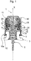
figure 1 illustre une vue en coupe longitudinale d'une tête de distribution montée sur un col d'un réservoir d'un flacon de produit fluide et équipée d'un système de fixation d'une pompe selon l'invention, avant montage initial ; - La
figure 2 reprend lafigure 1 après montage du système de fixation sur le col ; - La
figure 3 reprend lesfigures 1 et 2 , en une position où le système de fixation peut être retiré du col, après première utilisation on remonte sur le col pour une nouvelle utilisation ; - La
figure 4 illustre en perspective une vue éclatée du système de fixation selon l'invention comprenant un manchon (fig. 4b ), le collet d'articulation (fig. 4c ) et une frette (fig. 4d ). Sur lafigure 4a est illustré le col pour la fixation dudit système de fixation.
- The
figure 1 illustrates a view in longitudinal section of a dispensing head mounted on a neck of a reservoir of a bottle of fluid product and equipped with a system for fixing a pump according to the invention, before initial assembly; - The
figure 2 take it backfigure 1 after assembly of the fastening system on the collar; - The
picture 3figure 1 and2 , in a position where the fastening system can be removed from the neck, after first use, the neck is reassembled for a new use; - The
figure 4 illustrates in perspective an exploded view of the fastening system according to the invention comprising a sleeve (fig. 4b ), the articulation collar (fig. 4c ) and a fret (fig. 4d ). On thefigure 4a is illustrated the neck for fixing said fixing system.
En référence à la
Le produit fluide peut être un produit cosmétique, un produit pharmaceutique ou tout autre produit qui peut être utilement préservé dans un flacon. Le fluide peut être directement en contact avec le réservoir 3. Cela dit, le fluide peut être compris dans une poche souple située au sein dudit réservoir 3 de sorte qu'il n'est pas en contact avec le réservoir 3 mais avec ladite poche souple.The fluid product can be a cosmetic product, a pharmaceutical product or any other product which can usefully be stored in a bottle. The fluid can be directly in contact with the
Le réservoir 3 peut être indifféremment rigide ou déformable. Ceci étant, le réservoir 3 comprend, au niveau d'une partie supérieure, un col 4 et une ouverture 5 formée dans ledit col 4. Le col 4 est de préférence rigide. Il forme une gorge 7 avec le réservoir 3 et un chant périphérique 6 surmontant ladite gorge 7.
La tête de distribution 1 est équipée d'une pompe de distribution 2 du produit fluide contenu dans le réservoir 3. En sortie de la pompe, le fluide distribué est en particulier liquide, visqueux ou pâteux. La pompe de distribution 2 comprend un corps s'étendant selon un axe longitudinal central X correspondant à un axe médian du flacon. Le corps est de forme tubulaire notamment de révolution. En utilisation, la pompe de distribution 2 est maintenue immobile au niveau du col 4 au moyen d'un système de fixation selon l'invention. Cela étant, la pompe de distribution 2 peut être retirée de cet emplacement au moyen dudit système de fixation, par exemple à des fins de remplissage du réservoir 3. Autrement dit, la pompe de distribution 2 est amovible.The dispensing
Le système de fixation selon l'invention comprend un manchon 10 de fixation, un collet d'articulation 25 et une frette 30. Le collet d'articulation 25 et le manchon 10 sont montés mobiles l'un par rapport à l'autre entre une position de début de course PI (illustrée à la
Dans le mode de réalisation illustré à la
Le manchon 10 comprend une jupe 12 configurée pour venir en prise avec le col 4. À cet égard, la jupe 12 comprend une portion plane 14 apte à venir autour du chant périphérique 6, éventuellement en serrage. La jupe 12 comprend en outre des moyens de fixation 15 au col 4 s'étendant dans le prolongement de la portion plane 14.The
Préférentiellement, les moyens de fixation 15 consistent en des pattes souples aptes à effectuer des mouvements indépendamment les unes des autres. De préférence, les pattes souples 15 sont régulièrement espacées les unes des autres sur tout le pourtour de la jupe 12, c'est-à-dire que les pattes souples sont séparées les unes des autres par une distance constante. De préférence, également, les pattes souples 15 sont reliées à la portion plane 14 au moyen d'une portion charnière 15a. Elles adoptent alternativement une position de dégagement dans laquelle elles sont libres, c'est-à-dire qu'elles ne sont pas en prise avec le col 4 et une position d'engagement dans laquelle elles sont en prise avec ledit col 4. Les pattes souples 15 présentent, sur leurs faces internes, c'est-à-dire sur leurs faces tournées vers le col 4, une forme sensiblement complémentaire avec la forme de la gorge 7. Dans la configuration illustrée à la
Le manchon 10 comprend en outre un collet de guidage 16 ayant pour fonction principale de guider le collet d'articulation 25 dans ses mouvements. Le collet d'articulation 25 est plus précisément monté mobile autour du collet de guidage 16. En d'autres termes, il est apte à se déplacer relativement audit collet de guidage 16. Ledit collet de guidage 16 comprend des moyens de guidage dudit collet d'articulation 25, qui seront décrits plus en détail dans la suite. Le collet d'articulation 25, quant à lui, comprend des moyens de déplacement le long desdits moyens de guidage dudit collet de guidage 16. Le collet de guidage 16 et le collet d'articulation 25 forment donc un assemblage mécanique mobile. Le collet de guidage 16 est situé dans le prolongement longitudinal de la jupe 12.The
La frette 30 est de forme généralement cylindrique. Comme mentionné précédemment, elle est configurée pour actionner le déplacement dudit collet d'articulation 25. À cet égard, elle comprend une paroi intérieure 31 sur laquelle sont réparties angulairement des nervures 32. Les nervures sont plus précisément localisées sur une portion supérieure de la frette 30, le long de laquelle le collet d'articulation 25 est susceptible de se déplacer. Les nervures 32 permettent de solidariser la frette 30 et le collet d'articulation 25. En l'espèce, dans le mode de réalisation illustré aux
En outre, la frette 30 est configurée pour effectuer un mouvement de translation. Ce mouvement de translation de la frette 30 est rendu possible par la configuration du collet d'articulation 25 relativement à la jupe 12. Pour cela, la paroi extérieure 29 du collet d'articulation 25 est ici sensiblement alignée avec la portion plane 14 de la jupe 12 de sorte que la frette 30 est toujours maintenue en appui sur la paroi extérieure 29 et sur la portion plane 14. Incidemment, la frette 30 est ainsi capable de se déplacer longitudinalement, notamment entre une position proximale et une position distale relativement au manchon 10 en entraînant ledit collet d'articulation 25.Furthermore,
En étant ainsi configurée, la frette 30 est adaptée pour actionner le déplacement du collet d'articulation 25 entre une position haute PH de démontage et une position basse PB d'utilisation. Pour que le collet d'articulation 25 soit en mesure d'atteindre la position haute PH de démontage, la frette 30 doit se déplacer vers sa position distale. De même, pour que le collet d'articulation 25 puisse atteindre sa position basse d'utilisation PB, la frette 30 doit se déplacer vers sa position proximale. Il est à noter que dans la configuration illustrée sur la
En référence à la
En référence à la
Comme déjà indiqué, la
Dans cette configuration, le manchon 10 est monté sur le col 4, les pattes souples 15 étant libres. Le collet d'articulation 25 est en position basse PB d'utilisation. La frette 30 est dans une position escamotée correspondant à la position haute PH de démontage de la
Une fois la tête de distribution 1 ainsi mise en place, la frette 30 est abaissée en force selon un mouvement de translation et la tête de distribution passe dans la configuration de la
En référence aux
Préférentiellement, lorsque le collet d'articulation 25 est situé en position haute PH de démontage (
Alternativement, le collet d'articulation 25 et le manchon 10 peuvent être en butée, sans nécessairement que l'une desdites pièces soit encastrée dans l'autre pièce. En d'autres termes, il peut exister un jeu entre le collet d'articulation 25 et le manchon 10.Alternatively, the
Selon l'invention, les positions de début et de fin de course PI, PF sont situées de sorte que le collet d'articulation 25 soit apte à passer de la position haute PH de démontage (tel qu'illustré à la
En référence à la
Avantageusement, ces premiers moyens de guidage en translation comprennent un logement de début de course 19 situé à la position de début de course PI et un logement de fin de course 20 situé à la position de fin de course PF. Les logements de début et de fin de course 19, 20 forment, en combinaison, une rainure ou encore une encoche ayant une emprise de forme sensiblement rectangulaire sur le collet de guidage 16. Comme illustré à la
Précisons également que le logement de fin de course 20 comprend une extrémité plane 20a formant une discontinuité au niveau du bord libre supérieur du collet de guidage 16. Cela permet notamment de prédisposer le collet d'articulation 25 par rapport au collet de guidage 16 et facilite le montage initial du collet d'articulation sur le manchon 10.It should also be specified that the
Chacun desdits premiers moyens de guidage en translation comprend en outre un premier moyen de verrouillage 18. Les logements de début et de fin de course 19, 20 sont reliés par l'intermédiaire dudit premier moyen de verrouillage 18. Tout mouvement de translation du collet d'articulation 25 depuis la position haute PH de démontage vers la position basse PB d'utilisation implique que ledit collet d'articulation 25 soit en mesure de passer sur ledit premier moyen de verrouillage 18.Each of said first means for guiding in translation further comprises a first locking means 18. The start and end of
Ledit premier moyen de verrouillage 18 est configuré pour autoriser le déplacement en translation dudit collet d'articulation 25 de la position haute PH de démontage vers la position basse PB d'utilisation par translation par application d'une pression seuil. Ainsi, la gestuelle de l'utilisateur reste simple puisqu'elle ne nécessite qu'un simple appui et, en même temps, le mouvement du collet d'articulation 25 de la position haute PH de démontage à la position basse PB d'utilisation ne peut pas résulter d'un appui involontaire, mais d'une volonté, de la part de l'utilisateur de fermer le flacon.Said first locking means 18 is configured to allow said
De manière avantageuse, ledit premier moyen de verrouillage 18 forme un bossage, c'est-à-dire une surépaisseur entre lesdits logements de début et de fin de course 19, 20.Advantageously, said first locking means 18 forms a boss, that is to say an extra thickness between said start and end of
Préférentiellement, le premier moyen de verrouillage 18 comprend une portion de retenue 18a. Ladite portion de retenue 18a forme une portée pour le collet d'articulation 25 lorsque ce dernier est en position haute PH de démontage. La portion de retenue 18a est inclinée par rapport à un fond de la rainure. Plus précisément, elle fait un angle obtus avec le logement de fin de course 20. En étant ainsi configurée, la portion de retenue 18a permet aussi bien le maintien du collet d'articulation 25 que son glissement le long de la rainure, et donc depuis la position de fin de course PF vers la position de début de course PI.Preferably, the first locking means 18 comprises a retaining portion 18a. Said retaining
En outre, ledit premier moyen de verrouillage 18 comprend un rebord de verrouillage 18b. Ce rebord de verrouillage 18b s'étend depuis le fond de la rainure selon un plan transversal à la direction d'axe X. Plus précisément, il fait un angle droit avec le logement de début de course 19. Ainsi, une fois que le collet d'articulation 25 a atteint la position basse PB d'utilisation, il ne peut pas revenir à la position haute PB de démontage par translation le long de la rainure. Le rebord de verrouillage 18b forme donc une butée supérieure pour ledit collet d'articulation 25 en position basse PB d'utilisation.Furthermore, said first locking means 18 comprises a locking
Le premier moyen de verrouillage 18 comprend une arête 18c par laquelle la portion de retenue 18a est reliée au rebord de verrouillage 18b. L'arête 18c peut être assimilée à un sommet du bossage 18. Dans le mode de réalisation de la
Ainsi, lorsque le collet d'articulation 25 glisse, depuis le logement de fin de course 20 vers le logement de début de course 19, il passe successivement, sur la portion de retenue 18a et l'arête 18c.Thus, when the
En référence à la
Le collet extérieur 25 présente en outre un jonc intérieur 27 apte à venir en appui sur une surépaisseur 17 d'une bordure supérieure du manchon 10. Ainsi, lorsque le collet d'articulation 25 est en position haute PH de démontage, il est configuré pour rester au niveau de la position de fin de course 20, de sorte que le collet d'articulation 25 est maintenu au niveau du manchon 10. Lorsque le collet d'articulation 25 est en position basse PB d'utilisation, une bordure inférieure dudit collet d'articulation est apte à venir en appui sur la portée extérieure 13.The
En référence à la
De manière similaire aux premiers moyens de guidage en translation, ces seconds moyens de guidage sont positionnés sur le collet de guidage 16. Préférentiellement, ils s'étendent entre lesdites positions de début et de fin de course PI, PF. Chacun comporte à ses extrémités un logement de début de course 19 et un logement de fin de course 20. Il faut comprendre que s'il y a deux seconds moyens de guidage cela implique qu'il y a quatre logements au total puisque chacun des seconds moyens de guidage comprend un logement de début de course 19 et un logement de fin de course 20, dans la suite longitudinal l'un de l'autre, deux à deux.Similar to the first means for guiding in translation, these second guiding means are positioned on the
Le système de fixation selon l'invention est particulièrement ingénieux. En effet, les logements de début et de fin de course 19, 20 dont il est question dans les seconds moyens de guidage sont les mêmes logements qui forment les premiers moyens de guidage en translation, en l'espèce la rainure. L'architecture des moyens de guidage est ainsi optimisée pour permettre à la fois le remontage du système de fixation par appui simple de l'utilisateur mais également le vissage et le dévissage dudit système. En référence à l'exemple cité ci-dessus, on comprend bien que s'il y a quatre logements au total il y a donc deux premiers moyens de guidage en translation, chacun étant formé d'un logement de début de course 19 et d'un logement de fin de course 20. Cela dit, dans cette configuration, comme cela sera mieux compris dans la suite le logement de fin de course 20 d'un second moyen de guidage ne forme pas de rainure avec le logement de début de course 19 du même second moyen de guidage.The fastening system according to the invention is particularly ingenious. Indeed, the start and end of
Les seconds moyens de guidage sont configurés pour que le collet d'articulation 25 soit apte à effectuer un mouvement de rotation et de translation, notamment, de vissage autour dudit manchon 10 en vue de procéder au démontage du système de fixation.The second guide means are configured so that the
À cet égard, chacun des seconds moyens de guidage comprend avantageusement un tronçon hélicoïdal 21. Chaque tronçon hélicoïdal 21 comprend une première extrémité 22 comportant le logement de début de course 19 et une deuxième extrémité 23 comportant le logement de fin de course 20. Le nombre de seconds moyens de guidage est de préférence au moins égal à deux. Cela dit, ce nombre n'est pas limitatif.In this respect, each of the second guide means advantageously comprises a
Considérons que le manchon 10 comprend n, n étant un entier naturel, seconds moyens de guidage comprenant chacun un tronçon hélicoïdal 211, ...,21i, 21i+1,..., 21n, i étant un entier naturel avec i≥1 et i+1≤n. Chacun des tronçons hélicoïdaux 211, ...,21i, 21i+1,..., 21n, i étant un entier naturel avec i<n, comprend respectivement une première extrémité 221, ...,22i, 22i+1,..., 22n et une deuxième extrémité 231, ...,23i, 23i+1,..., 23n. Lesdits seconds moyens de guidage sont configurés de sorte que la première extrémité 221 d'un premier tronçon hélicoïdal 211 est située en vis-à-vis de la deuxième extrémité 23n d'un dernier tronçon hélicoïdal 21n et que chacune des autres premières extrémités 22i+1 des tronçons hélicoïdaux est située en vis-à-vis des autres deuxièmes extrémités 23i des tronçons hélicoïdaux qui les précèdent. En fait, les premières extrémités 221, ...,22i, 22i+1,..., 22n forment avec les deuxièmes extrémités 231, ...,23i, 23i+1,..., 23n les logements des premiers moyens de guidage en translation, en l'espèce des rainures, ce qui fait du système de fixation de l'invention un système à la fois pratique et ingénieux.Let us consider that the
Dans le cas particulier où n est égal à un, cela signifie qu'il y a un unique moyen de guidage comportant un tronçon hélicoïdal 21. Dans ce cas, on comprend que les extrémités du tronçon hélicoïdal 21 forment aussi les logements de début et de fin de course 19, 20 de la rainure permettant au collet d'articulation 25 de passer de la position haute PH de démontage à la position basse PB d'utilisation.In the particular case where n is equal to one, this means that there is a single guide means comprising a
Dans le cas particulier où n est égal à deux, cela signifie que le premier tronçon hélicoïdal 211 fait un demi-tour du collet de guidage 16 et le deuxième tronçon hélicoïdal 212 fait un demi-tour restant du collet de guidage 16. Dans cette configuration, la première extrémité 221 du premier tronçon hélicoïdal 211 est située en vis-à-vis de la deuxième extrémité 232 du deuxième tronçon hélicoïdal 212 et la première extrémité 222 du deuxième tronçon hélicoïdal 225 est située en vis-à-vis de la deuxième extrémité 231 du premier tronçon hélicoïdal. La première extrémité 221 et la deuxième extrémité 232 forment les logements d'un premier moyen de guidage en translation, tandis que la première extrémité 222 et la deuxième extrémité 231 forment les logements d'un deuxième moyen de guidage en translation.In the particular case where n is equal to two, this means that the first
Préférentiellement, chaque second moyen de guidage comprend des deuxièmes moyens de verrouillage 19b, 20b séparant les logements de début et de fin de course 19, 20 dudit tronçon hélicoïdal 21. Lesdits deuxièmes moyens de verrouillage 19b, 20b consistent en des bossages ou surépaisseurs dont une hauteur de saillie détermine la pression qui doit être appliquée pour que le collet d'articulation 25, en particulier la protubérance 26 quitte le logement de début ou de fin de course 19, 20 pour atteindre le tronçon hélicoïdal 21. En d'autres termes, les deuxièmes moyens de verrouillage 19b, 20b sont configurés pour autoriser le mouvement de rotation du collet d'articulation 25 autour dudit manchon 10 par application d'une pression seuil.Preferably, each second guide means comprises second locking means 19b, 20b separating the start and end of
Dans un mode de réalisation préféré, la surépaisseur 20b forme une butée franche (tel qu'illustré sur la
Dans un mode de réalisation préféré, la surépaisseur 20b est configurée de sorte que le dévissage du collet d'articulation 25 autour du manchon 10 soit autorisé par application d'une pression seuil (tel qu'illustré sur la
On comprend bien que lorsque la protubérance 26 se déplace depuis le logement de début de course 19 vers le logement de fin de course 20 en passant sur la surépaisseur 19b, le long du tronçon hélicoïdal 21 et sur la surépaisseur 20b, dans cet ordre il s'agit d'un dévissage. Le collet d'articulation 25 passe donc de la position basse PB d'utilisation à la position haute PH de démontage par dévissage. Pour rappel, c'est la seule alternative possible puisqu'il n'est pas possible de démonter le système de fixation par translation, notamment à cause de la butée 18b. Alternativement, lorsque la protubérance 26 se déplace depuis le logement de fin de course 20 vers le logement de début de course 19 en passant sur la surépaisseur 20b, le long du tronçon hélicoïdal 21 et sur la surépaisseur 19b, dans cet ordre il s'agit d'un vissage. Le collet d'articulation 25 passe donc de la position haute PH de démontage à la position basse d'utilisation PB par vissage. Ceci n'est pas obligatoire dans la présente invention puisque les premiers moyens de guidage en translation permettent de passer de la position haute PH de démontage à la position basse d'utilisation PB par translation du collet d'articulation 25.It will be understood that when the
Autrement dit, bien que le remontage du système de fixation selon l'invention soit possible par simple translation du collet d'articulation 25 depuis la position haute PH de démontage vers la position basse PB d'utilisation, il est également possible de monter le système de fixation par vissage. Ceci lui confère une grande souplesse d'utilisation.In other words, although the reassembly of the fixing system according to the invention is possible by simple translation of the
Claims (15)
- A system for attaching a distribution pump (2) to the neck (4) of a reservoir containing a fluid product, said system comprising:- a sleeve (10) comprising means (15) for attaching on said neck (4) and means (11) for hooking the pump (2);- a hinge collar (25), said hinge collar (25) and the sleeve (10) being mounted so as to be mobile relative to each other between an end of travel position (PF) and a start of travel position (PI);- a ring (30) configured to move said hinge collar (25) between a high position (PH) of disassembly, in which said attachment means are free, and a lower position of service (PB), in which said attachment means are engaged around said collar (4); said attachment system being characterised in that said start and end of travel positions (PI, PF) are located so that the hinge collar (25) is able to move from the high position (PH) of disassembly to the lower position of service (PB) by translation.
- The attachment system according to claim 1, wherein the sleeve (10) comprises first translational guiding means of said hinge collar (25) from the high position (PH) of disassembly to the lower position of service (PB).
- The attachment system according to claim 2, wherein the first translational guiding means comprise a start of travel housing (19) located at the start of travel position (PI) and an end of travel housing (20) located at the end of travel position (PF), the start and end of travel housings (19, 20) being located in the extension of each other.
- The attachment system according to claim 3, wherein the first translational guiding means comprise a first locking means (18), said start and end of travel housings (19, 20) being separated by said first locking means (18), said first locking means (18) being configured to allow the translational movement of said hinge collar (25) from the high position (PH) of disassembly to the lower position of service (PB) by application of a threshold pressure.
- The attachment system according to claim 4, wherein said first locking means (18) forms a boss.
- The attachment system according to one of claims 4 to 5, wherein said first locking means (18) comprises a retaining portion (18a) of the hinge collar (25) in the high position (PH) of disassembly, said retaining portion (18a) being located in the extension of said end of travel housing (20).
- The attachment system according to one of claims 4 to 6, wherein said first locking means (18) comprises a locking flange (18b) of the hinge collar (25) in the lower position of service (PB), said locking flange forming a stop for said hinge collar (25) in the start of travel housing (19).
- The attachment system according to any one of claims 1 to 7, wherein the sleeve (10) further comprises second guiding means for the hinge collar (25) comprising at their ends said start and end of travel positions (PI, PF).
- The attachment system according to claim 8 taken in its connection with any one of claims 3 to 7, wherein the second guiding means comprise a helical section (21) and second locking means (19b, 20b) separating the start and end of travel housings (19, 20) of said helical section (21).
- The attachment system according to claim 9, wherein said second locking means (19b, 20b) are configured to allow the rotational movement of the hinge collar (25) around said sleeve (10) by applying a threshold pressure.
- The attachment system according to claim 9, wherein the second locking means (20b) forms a free-stop.
- The attachment system according to any one of claims 8 to 11 when claim 8 depends on claim 2, wherein the hinge collar (25) comprises a protrusion (26) adapted to move along said first and second guiding means.
- The attachment system according to anyone of the preceding claims, wherein the ring (30) comprises an inner wall (31) comprising ribs (32) angularly distributed around a perimeter of said inner wall (31), such that said ring (30) is a tight fit on said hinge collar (25).
- A bottle for dispensing a fluid product, comprising a reservoir (3) for the fluid product, said reservoir being provided with a neck (4) defining an opening (5) for said reservoir, said bottle further comprising a distribution pump and an attachment system according to claims 1 to 13, said system allowing said pump to be attached to said neck.
- A bottle according to claim 14 wherein said neck (4) is provided with an anti-rotation system of said attachment system.
Applications Claiming Priority (1)
| Application Number | Priority Date | Filing Date | Title |
|---|---|---|---|
| FR1873690A FR3090596B1 (en) | 2018-12-20 | 2018-12-20 | FIXING SYSTEM FOR MOUNTING A DISTRIBUTION PUMP ON A BOTTLE AND BOTTLE OF ASSOCIATED FLUID PRODUCT |
Publications (2)
| Publication Number | Publication Date |
|---|---|
| EP3670000A1 EP3670000A1 (en) | 2020-06-24 |
| EP3670000B1 true EP3670000B1 (en) | 2022-04-27 |
Family
ID=66676744
Family Applications (1)
| Application Number | Title | Priority Date | Filing Date |
|---|---|---|---|
| EP19214620.7A Active EP3670000B1 (en) | 2018-12-20 | 2019-12-09 | Attachment system for mounting a dispensing pump to a bottle and associated fluid product bottle |
Country Status (4)
| Country | Link |
|---|---|
| US (1) | US11185876B2 (en) |
| EP (1) | EP3670000B1 (en) |
| CN (1) | CN111348323A (en) |
| FR (1) | FR3090596B1 (en) |
Families Citing this family (2)
| Publication number | Priority date | Publication date | Assignee | Title |
|---|---|---|---|---|
| FR3090596B1 (en) * | 2018-12-20 | 2021-01-08 | Albea Services | FIXING SYSTEM FOR MOUNTING A DISTRIBUTION PUMP ON A BOTTLE AND BOTTLE OF ASSOCIATED FLUID PRODUCT |
| FR3104143B1 (en) * | 2019-12-05 | 2021-12-10 | Dior Christian Parfums | Refillable packaging set for cosmetic product |
Family Cites Families (19)
| Publication number | Priority date | Publication date | Assignee | Title |
|---|---|---|---|---|
| GB1384370A (en) * | 1971-01-11 | 1975-02-19 | United Glass Ltd | Closures for containers |
| US4036385A (en) * | 1976-05-28 | 1977-07-19 | Morris Glenn H | Safety closure for containers |
| US5348174A (en) * | 1993-01-14 | 1994-09-20 | Eyelematic Manufacturing Co., Inc. | Metal flexible finger ferrule for flanged container closure |
| US5547132A (en) * | 1994-10-20 | 1996-08-20 | Calmar Inc. | Sprayer having variable spray pattern |
| DE19533134A1 (en) * | 1995-09-07 | 1997-03-13 | Chapon | Container closure for cosmetics or perfume containers |
| FR2790743B1 (en) * | 1999-03-08 | 2001-06-01 | Sofab | DEVICE FOR ASSEMBLING A PUMP ON THE NECK OF A CONTAINER WITH A HANGING COLLAR |
| FR2825989B1 (en) * | 2001-06-14 | 2003-12-12 | Valois Sa | FLUID PRODUCT DISPENSER |
| FR2925033B1 (en) * | 2007-12-12 | 2012-10-05 | Valois Sas | FLUID PRODUCT DISPENSER. |
| ATE524390T1 (en) * | 2008-11-25 | 2011-09-15 | Guala Dispensing Spa | CLOSURE SYSTEM BETWEEN A SPRAY DEVICE AND A CONTAINER |
| FR2943044B1 (en) * | 2009-03-13 | 2011-05-06 | Valois Sas | HEAD OF DISTRIBUTION OF FLUID PRODUCT |
| FR2948344B1 (en) * | 2009-07-27 | 2011-09-02 | Valois Sas | DETACHABLE FASTENING SYSTEM. |
| FR2948641B1 (en) * | 2009-07-28 | 2016-02-12 | Rexam Dispensing Sys | SYSTEM FOR FIXING A DISTRIBUTION PUMP ON THE BOTTOM OF A BOTTLE CONTAINING A FLUID PRODUCT |
| FR2952913B1 (en) * | 2009-11-26 | 2011-12-30 | Mbf Plastiques Sa | DEVICE FOR DISPENSING PRODUCTS CONTAINED IN A PAIR OF CONTAINERS, STORAGE ASSEMBLY COMPRISING SUCH A DEVICE AND METHOD FOR MOUNTING SUCH A DEVICE |
| FR2957903B1 (en) * | 2010-03-25 | 2014-01-24 | Valois Sas | FLUID PRODUCT DISPENSER. |
| FR2963610B1 (en) * | 2010-08-03 | 2012-08-31 | Valois Sas | FIXING SYSTEM AND DISPENSER OF FLUID PRODUCT USING SUCH A SYSTEM. |
| FR2975086B1 (en) * | 2011-05-13 | 2013-06-28 | Valois Sas | FLUID PRODUCT DISPENSER. |
| FR3032188B1 (en) * | 2014-12-19 | 2017-11-17 | Albea Le Treport | SYSTEM FOR ACTUATING A FLUID PRODUCT DISPENSING MEMBER |
| EP3162450A1 (en) * | 2015-11-02 | 2017-05-03 | Albea Thomaston Inc. | Dispensing device for dispensing a viscous or liquid product from a reservoir, and a receptacle comprising such a dispensing device |
| FR3090596B1 (en) * | 2018-12-20 | 2021-01-08 | Albea Services | FIXING SYSTEM FOR MOUNTING A DISTRIBUTION PUMP ON A BOTTLE AND BOTTLE OF ASSOCIATED FLUID PRODUCT |
-
2018
- 2018-12-20 FR FR1873690A patent/FR3090596B1/en active Active
-
2019
- 2019-12-09 EP EP19214620.7A patent/EP3670000B1/en active Active
- 2019-12-17 CN CN201911303781.0A patent/CN111348323A/en active Pending
- 2019-12-20 US US16/724,149 patent/US11185876B2/en active Active
Also Published As
| Publication number | Publication date |
|---|---|
| US20200197964A1 (en) | 2020-06-25 |
| CN111348323A (en) | 2020-06-30 |
| FR3090596A1 (en) | 2020-06-26 |
| FR3090596B1 (en) | 2021-01-08 |
| US11185876B2 (en) | 2021-11-30 |
| EP3670000A1 (en) | 2020-06-24 |
Similar Documents
| Publication | Publication Date | Title |
|---|---|---|
| EP1044893B1 (en) | Device for the extemporaneous mixture of at least two products, of which one is a powder | |
| EP2237897B1 (en) | Fluid product dispenser | |
| EP2459317B1 (en) | Removable attachment system | |
| EP3670000B1 (en) | Attachment system for mounting a dispensing pump to a bottle and associated fluid product bottle | |
| FR2688197A1 (en) | DISTRIBUTOR CLOSURE WITH TIP COLLAR. | |
| EP2285497B1 (en) | Device for dispensing a fluid product | |
| EP0466544B1 (en) | Dosing pump for pressure spraying with intrinsic safety | |
| EP3645172B1 (en) | Dual dispenser | |
| WO2002034412A1 (en) | Fluid product dispenser | |
| EP1651539B1 (en) | Fluid product dispensing head | |
| FR3098800A1 (en) | Fixing system for mounting a dispensing pump on a reservoir and associated dispensing bottle | |
| FR2927559A1 (en) | GAS CARTRIDGE ADAPTER FOR HIS ATTACHMENT TO A TRANSMISSION AND FILLING ELEMENT OF THE COMBUSTION CHAMBER OF A GAS FIXING APPARATUS AND ITS REMOVAL OF THE ELEMENT | |
| EP3094417B1 (en) | Dispensing device having a retractable head | |
| WO2021079060A1 (en) | Device for packaging a cosmetic product and assembly of the device using a connector having two internal attachment faces | |
| EP3893638A1 (en) | Cover for vessel comprising locking members for axially locking on an opening rim of the vessel | |
| WO2020212663A1 (en) | Fluid product dispenser | |
| WO2004103859A2 (en) | Distribution element for a liquid product | |
| WO2024084148A1 (en) | Cap comprising a guide ramp for a boss | |
| FR2802234A1 (en) | Safety lock cylinder comprises stator and rotor each with pin sliding in radial housing and anti-lock picking projecting stud on pin which limits sliding between rotor and stator | |
| WO2024056949A1 (en) | Source bottle and refillable dispenser assembly | |
| WO1998057817A1 (en) | Fuel tank cap with lock cylinder, in particular for motor vehicle | |
| FR3139446A1 (en) | Refillable source and dispenser bottle set | |
| FR3067014A1 (en) | ASSEMBLY OF A DISPENSING DEVICE FOR BOTTLE | |
| FR3123635A1 (en) | Fluid product dispenser | |
| FR3067013A1 (en) | ASSEMBLY OF A DISPENSING DEVICE FOR BOTTLE |
Legal Events
| Date | Code | Title | Description |
|---|---|---|---|
| PUAI | Public reference made under article 153(3) epc to a published international application that has entered the european phase |
Free format text: ORIGINAL CODE: 0009012 |
|
| STAA | Information on the status of an ep patent application or granted ep patent |
Free format text: STATUS: THE APPLICATION HAS BEEN PUBLISHED |
|
| AK | Designated contracting states |
Kind code of ref document: A1 Designated state(s): AL AT BE BG CH CY CZ DE DK EE ES FI FR GB GR HR HU IE IS IT LI LT LU LV MC MK MT NL NO PL PT RO RS SE SI SK SM TR |
|
| AX | Request for extension of the european patent |
Extension state: BA ME |
|
| STAA | Information on the status of an ep patent application or granted ep patent |
Free format text: STATUS: REQUEST FOR EXAMINATION WAS MADE |
|
| 17P | Request for examination filed |
Effective date: 20201203 |
|
| RBV | Designated contracting states (corrected) |
Designated state(s): AL AT BE BG CH CY CZ DE DK EE ES FI FR GB GR HR HU IE IS IT LI LT LU LV MC MK MT NL NO PL PT RO RS SE SI SK SM TR |
|
| GRAP | Despatch of communication of intention to grant a patent |
Free format text: ORIGINAL CODE: EPIDOSNIGR1 |
|
| STAA | Information on the status of an ep patent application or granted ep patent |
Free format text: STATUS: GRANT OF PATENT IS INTENDED |
|
| INTG | Intention to grant announced |
Effective date: 20211126 |
|
| GRAS | Grant fee paid |
Free format text: ORIGINAL CODE: EPIDOSNIGR3 |
|
| GRAA | (expected) grant |
Free format text: ORIGINAL CODE: 0009210 |
|
| STAA | Information on the status of an ep patent application or granted ep patent |
Free format text: STATUS: THE PATENT HAS BEEN GRANTED |
|
| AK | Designated contracting states |
Kind code of ref document: B1 Designated state(s): AL AT BE BG CH CY CZ DE DK EE ES FI FR GB GR HR HU IE IS IT LI LT LU LV MC MK MT NL NO PL PT RO RS SE SI SK SM TR |
|
| REG | Reference to a national code |
Ref country code: GB Ref legal event code: FG4D Free format text: NOT ENGLISH |
|
| REG | Reference to a national code |
Ref country code: CH Ref legal event code: EP |
|
| REG | Reference to a national code |
Ref country code: DE Ref legal event code: R096 Ref document number: 602019014111 Country of ref document: DE |
|
| REG | Reference to a national code |
Ref country code: AT Ref legal event code: REF Ref document number: 1486517 Country of ref document: AT Kind code of ref document: T Effective date: 20220515 |
|
| REG | Reference to a national code |
Ref country code: IE Ref legal event code: FG4D Free format text: LANGUAGE OF EP DOCUMENT: FRENCH |
|
| REG | Reference to a national code |
Ref country code: LT Ref legal event code: MG9D |
|
| REG | Reference to a national code |
Ref country code: NL Ref legal event code: MP Effective date: 20220427 |
|
| REG | Reference to a national code |
Ref country code: AT Ref legal event code: MK05 Ref document number: 1486517 Country of ref document: AT Kind code of ref document: T Effective date: 20220427 |
|
| PG25 | Lapsed in a contracting state [announced via postgrant information from national office to epo] |
Ref country code: NL Free format text: LAPSE BECAUSE OF FAILURE TO SUBMIT A TRANSLATION OF THE DESCRIPTION OR TO PAY THE FEE WITHIN THE PRESCRIBED TIME-LIMIT Effective date: 20220427 |
|
| PG25 | Lapsed in a contracting state [announced via postgrant information from national office to epo] |
Ref country code: SE Free format text: LAPSE BECAUSE OF FAILURE TO SUBMIT A TRANSLATION OF THE DESCRIPTION OR TO PAY THE FEE WITHIN THE PRESCRIBED TIME-LIMIT Effective date: 20220427 Ref country code: PT Free format text: LAPSE BECAUSE OF FAILURE TO SUBMIT A TRANSLATION OF THE DESCRIPTION OR TO PAY THE FEE WITHIN THE PRESCRIBED TIME-LIMIT Effective date: 20220829 Ref country code: NO Free format text: LAPSE BECAUSE OF FAILURE TO SUBMIT A TRANSLATION OF THE DESCRIPTION OR TO PAY THE FEE WITHIN THE PRESCRIBED TIME-LIMIT Effective date: 20220727 Ref country code: LT Free format text: LAPSE BECAUSE OF FAILURE TO SUBMIT A TRANSLATION OF THE DESCRIPTION OR TO PAY THE FEE WITHIN THE PRESCRIBED TIME-LIMIT Effective date: 20220427 Ref country code: HR Free format text: LAPSE BECAUSE OF FAILURE TO SUBMIT A TRANSLATION OF THE DESCRIPTION OR TO PAY THE FEE WITHIN THE PRESCRIBED TIME-LIMIT Effective date: 20220427 Ref country code: GR Free format text: LAPSE BECAUSE OF FAILURE TO SUBMIT A TRANSLATION OF THE DESCRIPTION OR TO PAY THE FEE WITHIN THE PRESCRIBED TIME-LIMIT Effective date: 20220728 Ref country code: FI Free format text: LAPSE BECAUSE OF FAILURE TO SUBMIT A TRANSLATION OF THE DESCRIPTION OR TO PAY THE FEE WITHIN THE PRESCRIBED TIME-LIMIT Effective date: 20220427 Ref country code: ES Free format text: LAPSE BECAUSE OF FAILURE TO SUBMIT A TRANSLATION OF THE DESCRIPTION OR TO PAY THE FEE WITHIN THE PRESCRIBED TIME-LIMIT Effective date: 20220427 Ref country code: BG Free format text: LAPSE BECAUSE OF FAILURE TO SUBMIT A TRANSLATION OF THE DESCRIPTION OR TO PAY THE FEE WITHIN THE PRESCRIBED TIME-LIMIT Effective date: 20220727 Ref country code: AT Free format text: LAPSE BECAUSE OF FAILURE TO SUBMIT A TRANSLATION OF THE DESCRIPTION OR TO PAY THE FEE WITHIN THE PRESCRIBED TIME-LIMIT Effective date: 20220427 |
|
| PG25 | Lapsed in a contracting state [announced via postgrant information from national office to epo] |
Ref country code: RS Free format text: LAPSE BECAUSE OF FAILURE TO SUBMIT A TRANSLATION OF THE DESCRIPTION OR TO PAY THE FEE WITHIN THE PRESCRIBED TIME-LIMIT Effective date: 20220427 Ref country code: PL Free format text: LAPSE BECAUSE OF FAILURE TO SUBMIT A TRANSLATION OF THE DESCRIPTION OR TO PAY THE FEE WITHIN THE PRESCRIBED TIME-LIMIT Effective date: 20220427 Ref country code: LV Free format text: LAPSE BECAUSE OF FAILURE TO SUBMIT A TRANSLATION OF THE DESCRIPTION OR TO PAY THE FEE WITHIN THE PRESCRIBED TIME-LIMIT Effective date: 20220427 Ref country code: IS Free format text: LAPSE BECAUSE OF FAILURE TO SUBMIT A TRANSLATION OF THE DESCRIPTION OR TO PAY THE FEE WITHIN THE PRESCRIBED TIME-LIMIT Effective date: 20220827 |
|
| REG | Reference to a national code |
Ref country code: DE Ref legal event code: R097 Ref document number: 602019014111 Country of ref document: DE |
|
| PG25 | Lapsed in a contracting state [announced via postgrant information from national office to epo] |
Ref country code: SM Free format text: LAPSE BECAUSE OF FAILURE TO SUBMIT A TRANSLATION OF THE DESCRIPTION OR TO PAY THE FEE WITHIN THE PRESCRIBED TIME-LIMIT Effective date: 20220427 Ref country code: SK Free format text: LAPSE BECAUSE OF FAILURE TO SUBMIT A TRANSLATION OF THE DESCRIPTION OR TO PAY THE FEE WITHIN THE PRESCRIBED TIME-LIMIT Effective date: 20220427 Ref country code: RO Free format text: LAPSE BECAUSE OF FAILURE TO SUBMIT A TRANSLATION OF THE DESCRIPTION OR TO PAY THE FEE WITHIN THE PRESCRIBED TIME-LIMIT Effective date: 20220427 Ref country code: EE Free format text: LAPSE BECAUSE OF FAILURE TO SUBMIT A TRANSLATION OF THE DESCRIPTION OR TO PAY THE FEE WITHIN THE PRESCRIBED TIME-LIMIT Effective date: 20220427 Ref country code: DK Free format text: LAPSE BECAUSE OF FAILURE TO SUBMIT A TRANSLATION OF THE DESCRIPTION OR TO PAY THE FEE WITHIN THE PRESCRIBED TIME-LIMIT Effective date: 20220427 Ref country code: CZ Free format text: LAPSE BECAUSE OF FAILURE TO SUBMIT A TRANSLATION OF THE DESCRIPTION OR TO PAY THE FEE WITHIN THE PRESCRIBED TIME-LIMIT Effective date: 20220427 |
|
| PLBE | No opposition filed within time limit |
Free format text: ORIGINAL CODE: 0009261 |
|
| STAA | Information on the status of an ep patent application or granted ep patent |
Free format text: STATUS: NO OPPOSITION FILED WITHIN TIME LIMIT |
|
| PG25 | Lapsed in a contracting state [announced via postgrant information from national office to epo] |
Ref country code: AL Free format text: LAPSE BECAUSE OF FAILURE TO SUBMIT A TRANSLATION OF THE DESCRIPTION OR TO PAY THE FEE WITHIN THE PRESCRIBED TIME-LIMIT Effective date: 20220427 |
|
| 26N | No opposition filed |
Effective date: 20230130 |
|
| PG25 | Lapsed in a contracting state [announced via postgrant information from national office to epo] |
Ref country code: SI Free format text: LAPSE BECAUSE OF FAILURE TO SUBMIT A TRANSLATION OF THE DESCRIPTION OR TO PAY THE FEE WITHIN THE PRESCRIBED TIME-LIMIT Effective date: 20220427 |
|
| PGFP | Annual fee paid to national office [announced via postgrant information from national office to epo] |
Ref country code: DE Payment date: 20221228 Year of fee payment: 4 |
|
| REG | Reference to a national code |
Ref country code: CH Ref legal event code: PL |
|
| REG | Reference to a national code |
Ref country code: BE Ref legal event code: MM Effective date: 20221231 |
|
| PG25 | Lapsed in a contracting state [announced via postgrant information from national office to epo] |
Ref country code: LU Free format text: LAPSE BECAUSE OF NON-PAYMENT OF DUE FEES Effective date: 20221209 |
|
| PG25 | Lapsed in a contracting state [announced via postgrant information from national office to epo] |
Ref country code: LI Free format text: LAPSE BECAUSE OF NON-PAYMENT OF DUE FEES Effective date: 20221231 Ref country code: IE Free format text: LAPSE BECAUSE OF NON-PAYMENT OF DUE FEES Effective date: 20221209 Ref country code: CH Free format text: LAPSE BECAUSE OF NON-PAYMENT OF DUE FEES Effective date: 20221231 |
|
| PG25 | Lapsed in a contracting state [announced via postgrant information from national office to epo] |
Ref country code: BE Free format text: LAPSE BECAUSE OF NON-PAYMENT OF DUE FEES Effective date: 20221231 |
|
| PGFP | Annual fee paid to national office [announced via postgrant information from national office to epo] |
Ref country code: GB Payment date: 20231227 Year of fee payment: 5 |
|
| PG25 | Lapsed in a contracting state [announced via postgrant information from national office to epo] |
Ref country code: IT Free format text: LAPSE BECAUSE OF FAILURE TO SUBMIT A TRANSLATION OF THE DESCRIPTION OR TO PAY THE FEE WITHIN THE PRESCRIBED TIME-LIMIT Effective date: 20220427 |
|
| PGFP | Annual fee paid to national office [announced via postgrant information from national office to epo] |
Ref country code: FR Payment date: 20231227 Year of fee payment: 5 |
|
| PG25 | Lapsed in a contracting state [announced via postgrant information from national office to epo] |
Ref country code: HU Free format text: LAPSE BECAUSE OF FAILURE TO SUBMIT A TRANSLATION OF THE DESCRIPTION OR TO PAY THE FEE WITHIN THE PRESCRIBED TIME-LIMIT; INVALID AB INITIO Effective date: 20191209 |