EP3669915B1 - Inhalatorsteuerungsclip und inhalatorsteuerungsanordnung - Google Patents
Inhalatorsteuerungsclip und inhalatorsteuerungsanordnung Download PDFInfo
- Publication number
- EP3669915B1 EP3669915B1 EP19156518.3A EP19156518A EP3669915B1 EP 3669915 B1 EP3669915 B1 EP 3669915B1 EP 19156518 A EP19156518 A EP 19156518A EP 3669915 B1 EP3669915 B1 EP 3669915B1
- Authority
- EP
- European Patent Office
- Prior art keywords
- unit
- inhaler
- sensor
- ambient atmosphere
- control clip
- Prior art date
- Legal status (The legal status is an assumption and is not a legal conclusion. Google has not performed a legal analysis and makes no representation as to the accuracy of the status listed.)
- Active
Links
Images


Classifications
-
- A—HUMAN NECESSITIES
- A61—MEDICAL OR VETERINARY SCIENCE; HYGIENE
- A61M—DEVICES FOR INTRODUCING MEDIA INTO, OR ONTO, THE BODY; DEVICES FOR TRANSDUCING BODY MEDIA OR FOR TAKING MEDIA FROM THE BODY; DEVICES FOR PRODUCING OR ENDING SLEEP OR STUPOR
- A61M15/00—Inhalators
-
- G—PHYSICS
- G16—INFORMATION AND COMMUNICATION TECHNOLOGY [ICT] SPECIALLY ADAPTED FOR SPECIFIC APPLICATION FIELDS
- G16H—HEALTHCARE INFORMATICS, i.e. INFORMATION AND COMMUNICATION TECHNOLOGY [ICT] SPECIALLY ADAPTED FOR THE HANDLING OR PROCESSING OF MEDICAL OR HEALTHCARE DATA
- G16H20/00—ICT specially adapted for therapies or health-improving plans, e.g. for handling prescriptions, for steering therapy or for monitoring patient compliance
- G16H20/10—ICT specially adapted for therapies or health-improving plans, e.g. for handling prescriptions, for steering therapy or for monitoring patient compliance relating to drugs or medications, e.g. for ensuring correct administration to patients
- G16H20/13—ICT specially adapted for therapies or health-improving plans, e.g. for handling prescriptions, for steering therapy or for monitoring patient compliance relating to drugs or medications, e.g. for ensuring correct administration to patients delivered from dispensers
-
- G—PHYSICS
- G16—INFORMATION AND COMMUNICATION TECHNOLOGY [ICT] SPECIALLY ADAPTED FOR SPECIFIC APPLICATION FIELDS
- G16H—HEALTHCARE INFORMATICS, i.e. INFORMATION AND COMMUNICATION TECHNOLOGY [ICT] SPECIALLY ADAPTED FOR THE HANDLING OR PROCESSING OF MEDICAL OR HEALTHCARE DATA
- G16H40/00—ICT specially adapted for the management or administration of healthcare resources or facilities; ICT specially adapted for the management or operation of medical equipment or devices
- G16H40/60—ICT specially adapted for the management or administration of healthcare resources or facilities; ICT specially adapted for the management or operation of medical equipment or devices for the operation of medical equipment or devices
-
- G—PHYSICS
- G16—INFORMATION AND COMMUNICATION TECHNOLOGY [ICT] SPECIALLY ADAPTED FOR SPECIFIC APPLICATION FIELDS
- G16H—HEALTHCARE INFORMATICS, i.e. INFORMATION AND COMMUNICATION TECHNOLOGY [ICT] SPECIALLY ADAPTED FOR THE HANDLING OR PROCESSING OF MEDICAL OR HEALTHCARE DATA
- G16H50/00—ICT specially adapted for medical diagnosis, medical simulation or medical data mining; ICT specially adapted for detecting, monitoring or modelling epidemics or pandemics
- G16H50/30—ICT specially adapted for medical diagnosis, medical simulation or medical data mining; ICT specially adapted for detecting, monitoring or modelling epidemics or pandemics for calculating health indices; for individual health risk assessment
-
- A—HUMAN NECESSITIES
- A61—MEDICAL OR VETERINARY SCIENCE; HYGIENE
- A61B—DIAGNOSIS; SURGERY; IDENTIFICATION
- A61B2560/00—Constructional details of operational features of apparatus; Accessories for medical measuring apparatus
- A61B2560/02—Operational features
- A61B2560/0242—Operational features adapted to measure environmental factors, e.g. temperature, pollution
-
- A—HUMAN NECESSITIES
- A61—MEDICAL OR VETERINARY SCIENCE; HYGIENE
- A61M—DEVICES FOR INTRODUCING MEDIA INTO, OR ONTO, THE BODY; DEVICES FOR TRANSDUCING BODY MEDIA OR FOR TAKING MEDIA FROM THE BODY; DEVICES FOR PRODUCING OR ENDING SLEEP OR STUPOR
- A61M15/00—Inhalators
- A61M15/009—Inhalators using medicine packages with incorporated spraying means, e.g. aerosol cans
-
- A—HUMAN NECESSITIES
- A61—MEDICAL OR VETERINARY SCIENCE; HYGIENE
- A61M—DEVICES FOR INTRODUCING MEDIA INTO, OR ONTO, THE BODY; DEVICES FOR TRANSDUCING BODY MEDIA OR FOR TAKING MEDIA FROM THE BODY; DEVICES FOR PRODUCING OR ENDING SLEEP OR STUPOR
- A61M16/00—Devices for influencing the respiratory system of patients by gas treatment, e.g. mouth-to-mouth respiration; Tracheal tubes
- A61M16/10—Preparation of respiratory gases or vapours
- A61M16/14—Preparation of respiratory gases or vapours by mixing different fluids, one of them being in a liquid phase
- A61M16/16—Devices to humidify the respiration air
- A61M16/161—Devices to humidify the respiration air with means for measuring the humidity
-
- A—HUMAN NECESSITIES
- A61—MEDICAL OR VETERINARY SCIENCE; HYGIENE
- A61M—DEVICES FOR INTRODUCING MEDIA INTO, OR ONTO, THE BODY; DEVICES FOR TRANSDUCING BODY MEDIA OR FOR TAKING MEDIA FROM THE BODY; DEVICES FOR PRODUCING OR ENDING SLEEP OR STUPOR
- A61M2205/00—General characteristics of the apparatus
- A61M2205/18—General characteristics of the apparatus with alarm
-
- A—HUMAN NECESSITIES
- A61—MEDICAL OR VETERINARY SCIENCE; HYGIENE
- A61M—DEVICES FOR INTRODUCING MEDIA INTO, OR ONTO, THE BODY; DEVICES FOR TRANSDUCING BODY MEDIA OR FOR TAKING MEDIA FROM THE BODY; DEVICES FOR PRODUCING OR ENDING SLEEP OR STUPOR
- A61M2205/00—General characteristics of the apparatus
- A61M2205/33—Controlling, regulating or measuring
- A61M2205/332—Force measuring means
-
- A—HUMAN NECESSITIES
- A61—MEDICAL OR VETERINARY SCIENCE; HYGIENE
- A61M—DEVICES FOR INTRODUCING MEDIA INTO, OR ONTO, THE BODY; DEVICES FOR TRANSDUCING BODY MEDIA OR FOR TAKING MEDIA FROM THE BODY; DEVICES FOR PRODUCING OR ENDING SLEEP OR STUPOR
- A61M2205/00—General characteristics of the apparatus
- A61M2205/33—Controlling, regulating or measuring
- A61M2205/3331—Pressure; Flow
- A61M2205/3358—Measuring barometric pressure, e.g. for compensation
-
- A—HUMAN NECESSITIES
- A61—MEDICAL OR VETERINARY SCIENCE; HYGIENE
- A61M—DEVICES FOR INTRODUCING MEDIA INTO, OR ONTO, THE BODY; DEVICES FOR TRANSDUCING BODY MEDIA OR FOR TAKING MEDIA FROM THE BODY; DEVICES FOR PRODUCING OR ENDING SLEEP OR STUPOR
- A61M2205/00—General characteristics of the apparatus
- A61M2205/33—Controlling, regulating or measuring
- A61M2205/3368—Temperature
-
- A—HUMAN NECESSITIES
- A61—MEDICAL OR VETERINARY SCIENCE; HYGIENE
- A61M—DEVICES FOR INTRODUCING MEDIA INTO, OR ONTO, THE BODY; DEVICES FOR TRANSDUCING BODY MEDIA OR FOR TAKING MEDIA FROM THE BODY; DEVICES FOR PRODUCING OR ENDING SLEEP OR STUPOR
- A61M2205/00—General characteristics of the apparatus
- A61M2205/33—Controlling, regulating or measuring
- A61M2205/3375—Acoustical, e.g. ultrasonic, measuring means
-
- A—HUMAN NECESSITIES
- A61—MEDICAL OR VETERINARY SCIENCE; HYGIENE
- A61M—DEVICES FOR INTRODUCING MEDIA INTO, OR ONTO, THE BODY; DEVICES FOR TRANSDUCING BODY MEDIA OR FOR TAKING MEDIA FROM THE BODY; DEVICES FOR PRODUCING OR ENDING SLEEP OR STUPOR
- A61M2205/00—General characteristics of the apparatus
- A61M2205/35—Communication
- A61M2205/3546—Range
- A61M2205/3553—Range remote, e.g. between patient's home and doctor's office
-
- A—HUMAN NECESSITIES
- A61—MEDICAL OR VETERINARY SCIENCE; HYGIENE
- A61M—DEVICES FOR INTRODUCING MEDIA INTO, OR ONTO, THE BODY; DEVICES FOR TRANSDUCING BODY MEDIA OR FOR TAKING MEDIA FROM THE BODY; DEVICES FOR PRODUCING OR ENDING SLEEP OR STUPOR
- A61M2205/00—General characteristics of the apparatus
- A61M2205/35—Communication
- A61M2205/3546—Range
- A61M2205/3561—Range local, e.g. within room or hospital
-
- A—HUMAN NECESSITIES
- A61—MEDICAL OR VETERINARY SCIENCE; HYGIENE
- A61M—DEVICES FOR INTRODUCING MEDIA INTO, OR ONTO, THE BODY; DEVICES FOR TRANSDUCING BODY MEDIA OR FOR TAKING MEDIA FROM THE BODY; DEVICES FOR PRODUCING OR ENDING SLEEP OR STUPOR
- A61M2205/00—General characteristics of the apparatus
- A61M2205/35—Communication
- A61M2205/3576—Communication with non implanted data transmission devices, e.g. using external transmitter or receiver
- A61M2205/3592—Communication with non implanted data transmission devices, e.g. using external transmitter or receiver using telemetric means, e.g. radio or optical transmission
-
- A—HUMAN NECESSITIES
- A61—MEDICAL OR VETERINARY SCIENCE; HYGIENE
- A61M—DEVICES FOR INTRODUCING MEDIA INTO, OR ONTO, THE BODY; DEVICES FOR TRANSDUCING BODY MEDIA OR FOR TAKING MEDIA FROM THE BODY; DEVICES FOR PRODUCING OR ENDING SLEEP OR STUPOR
- A61M2205/00—General characteristics of the apparatus
- A61M2205/50—General characteristics of the apparatus with microprocessors or computers
- A61M2205/502—User interfaces, e.g. screens or keyboards
- A61M2205/505—Touch-screens; Virtual keyboard or keypads; Virtual buttons; Soft keys; Mouse touches
-
- A—HUMAN NECESSITIES
- A61—MEDICAL OR VETERINARY SCIENCE; HYGIENE
- A61M—DEVICES FOR INTRODUCING MEDIA INTO, OR ONTO, THE BODY; DEVICES FOR TRANSDUCING BODY MEDIA OR FOR TAKING MEDIA FROM THE BODY; DEVICES FOR PRODUCING OR ENDING SLEEP OR STUPOR
- A61M2205/00—General characteristics of the apparatus
- A61M2205/58—Means for facilitating use, e.g. by people with impaired vision
- A61M2205/581—Means for facilitating use, e.g. by people with impaired vision by audible feedback
-
- A—HUMAN NECESSITIES
- A61—MEDICAL OR VETERINARY SCIENCE; HYGIENE
- A61M—DEVICES FOR INTRODUCING MEDIA INTO, OR ONTO, THE BODY; DEVICES FOR TRANSDUCING BODY MEDIA OR FOR TAKING MEDIA FROM THE BODY; DEVICES FOR PRODUCING OR ENDING SLEEP OR STUPOR
- A61M2205/00—General characteristics of the apparatus
- A61M2205/58—Means for facilitating use, e.g. by people with impaired vision
- A61M2205/583—Means for facilitating use, e.g. by people with impaired vision by visual feedback
- A61M2205/584—Means for facilitating use, e.g. by people with impaired vision by visual feedback having a color code
-
- A—HUMAN NECESSITIES
- A61—MEDICAL OR VETERINARY SCIENCE; HYGIENE
- A61M—DEVICES FOR INTRODUCING MEDIA INTO, OR ONTO, THE BODY; DEVICES FOR TRANSDUCING BODY MEDIA OR FOR TAKING MEDIA FROM THE BODY; DEVICES FOR PRODUCING OR ENDING SLEEP OR STUPOR
- A61M2205/00—General characteristics of the apparatus
- A61M2205/58—Means for facilitating use, e.g. by people with impaired vision
- A61M2205/587—Lighting arrangements
-
- A—HUMAN NECESSITIES
- A61—MEDICAL OR VETERINARY SCIENCE; HYGIENE
- A61M—DEVICES FOR INTRODUCING MEDIA INTO, OR ONTO, THE BODY; DEVICES FOR TRANSDUCING BODY MEDIA OR FOR TAKING MEDIA FROM THE BODY; DEVICES FOR PRODUCING OR ENDING SLEEP OR STUPOR
- A61M2205/00—General characteristics of the apparatus
- A61M2205/60—General characteristics of the apparatus with identification means
- A61M2205/6018—General characteristics of the apparatus with identification means providing set-up signals for the apparatus configuration
-
- A—HUMAN NECESSITIES
- A61—MEDICAL OR VETERINARY SCIENCE; HYGIENE
- A61M—DEVICES FOR INTRODUCING MEDIA INTO, OR ONTO, THE BODY; DEVICES FOR TRANSDUCING BODY MEDIA OR FOR TAKING MEDIA FROM THE BODY; DEVICES FOR PRODUCING OR ENDING SLEEP OR STUPOR
- A61M2205/00—General characteristics of the apparatus
- A61M2205/60—General characteristics of the apparatus with identification means
- A61M2205/6063—Optical identification systems
- A61M2205/6072—Bar codes
-
- A—HUMAN NECESSITIES
- A61—MEDICAL OR VETERINARY SCIENCE; HYGIENE
- A61M—DEVICES FOR INTRODUCING MEDIA INTO, OR ONTO, THE BODY; DEVICES FOR TRANSDUCING BODY MEDIA OR FOR TAKING MEDIA FROM THE BODY; DEVICES FOR PRODUCING OR ENDING SLEEP OR STUPOR
- A61M2205/00—General characteristics of the apparatus
- A61M2205/82—Internal energy supply devices
- A61M2205/8206—Internal energy supply devices battery-operated
-
- A—HUMAN NECESSITIES
- A61—MEDICAL OR VETERINARY SCIENCE; HYGIENE
- A61M—DEVICES FOR INTRODUCING MEDIA INTO, OR ONTO, THE BODY; DEVICES FOR TRANSDUCING BODY MEDIA OR FOR TAKING MEDIA FROM THE BODY; DEVICES FOR PRODUCING OR ENDING SLEEP OR STUPOR
- A61M2209/00—Ancillary equipment
- A61M2209/04—Tools for specific apparatus
-
- G—PHYSICS
- G01—MEASURING; TESTING
- G01N—INVESTIGATING OR ANALYSING MATERIALS BY DETERMINING THEIR CHEMICAL OR PHYSICAL PROPERTIES
- G01N1/00—Sampling; Preparing specimens for investigation
- G01N1/02—Devices for withdrawing samples
- G01N1/22—Devices for withdrawing samples in the gaseous state
- G01N1/2273—Atmospheric sampling
-
- G—PHYSICS
- G01—MEASURING; TESTING
- G01N—INVESTIGATING OR ANALYSING MATERIALS BY DETERMINING THEIR CHEMICAL OR PHYSICAL PROPERTIES
- G01N15/00—Investigating characteristics of particles; Investigating permeability, pore-volume, or surface-area of porous materials
- G01N15/06—Investigating concentration of particle suspensions
-
- G—PHYSICS
- G01—MEASURING; TESTING
- G01N—INVESTIGATING OR ANALYSING MATERIALS BY DETERMINING THEIR CHEMICAL OR PHYSICAL PROPERTIES
- G01N15/00—Investigating characteristics of particles; Investigating permeability, pore-volume, or surface-area of porous materials
- G01N2015/0042—Investigating dispersion of solids
- G01N2015/0046—Investigating dispersion of solids in gas, e.g. smoke
-
- G—PHYSICS
- G01—MEASURING; TESTING
- G01N—INVESTIGATING OR ANALYSING MATERIALS BY DETERMINING THEIR CHEMICAL OR PHYSICAL PROPERTIES
- G01N33/00—Investigating or analysing materials by specific methods not covered by groups G01N1/00 - G01N31/00
- G01N33/0004—Gaseous mixtures, e.g. polluted air
Definitions
- the present invention relates to an inhaler control clip and an inhaler control arrangement.
- EP3053620 describes an intelligent inhaler holster including a sensor module to sense various environmental parameters.
- DE 10 2016 219 759 A1 describes an inhaler with a sensor unit.
- the sensor unit in the inhaler detects, among other quantities, at least one quantity of the ambient atmosphere quantity for transmission to a receiver on the side of an attending physician.
- an inhaler control clip comprises:
- the sensor unit of the inhaler control clip measures at least one quantity indicative of a concentration of at least one gas component or particulate in an ambient atmosphere.
- the measurement thus provides information about a user's atmospheric environment. This information provides indications for possible health risks for the respiratory tract of the user of the inhaler that may require measures for protection or treatment.
- the inhaler control clip has a communication unit comprising a communication interface to an external configuration device.
- the communication unit is configured to receive via the communication interface configuration data indicative of one or more sampling points in time for triggering performance of the measurement and of at least one reference value for ambient atmosphere composition.
- the warning unit of the inhaler control clip provides immediate information upon determining that the concentration of the at least one gas component or particulate in the ambient atmosphere exceeds the reference value, and thus warns the user in case a current quality of the ambient atmosphere forms a health risk.
- control unit to rigger performance of the measurement at configurable sampling points in time using the configuration data allows dynamically adjusting a frequency of the measurement of the at least one quantity indicative of the concentration of the at least one gas component or particulate in the ambient atmosphere. Based on such an adjusted frequency of measurement, the user receives reliable information for judging the current health risk and for making decisions on prevention or treatment measures, or for instance on moving to another, less polluted area.
- the configuration data is provided from an external source.
- the inhaler control clip of the present invention advantageously provides flexibility in the implementation of such an external source of configuration data, be it in the form of an algorithm running on an external configuration device worn by the user, or from a more remote source, such as an attending physician.
- a preferred embodiment of the inhaler control clip has the control unit configured to trigger the sensor unit to perform the measurement at a plurality of sampling points in time within a configurable threshold time span.
- the warning unit is configured to provide the warning signal, which determines that the concentration of the at least one gas component or particulate in the ambient atmosphere exceeds the reference value at all the sampling points in time within the threshold time span.
- the communication unit of another embodiment of the inhaler control clip is configured to receive via the communication interface a plurality of reference values for the ambient atmosphere composition.
- the reference values are associated with different gas components or particulates.
- the warning unit is configured to provide the warning signal upon determining that a combination of at least two of the reference values is exceeded by the concentration of the at least one gas component or particulates in the ambient atmosphere. This allows reacting to more complex pollution scenarios.
- the configuration data additionally provides different combinations of the reference value and the threshold time span for a given gas component or particulate. For instance, a single measurement exceeding a high first reference value of a certain gas component or particulate may trigger a warning signal, just like a series of measurements exceeding a comparatively lower second reference value extending over a longer threshold time span for the same gas component or particulate will trigger the warning signal.
- the warning unit of this embodiment is configured to determine whether the concentration of the at least one gas component or particulate in the ambient atmosphere exceeds each of the reference values for each of the associated threshold time spans, and to provide the warning signal upon determining that one of the criteria defined by the respective pairs of reference value and assigned threshold time span is fulfilled.
- the configuration data additionally assigns a weight factor to each of the plurality of reference values and associated threshold time spans, preferably based on a configurable setting of user-individual sensitivities to certain gas components or particulates in the ambient atmosphere. This allows the individual user making an appropriate treatment decision in view of his personal sensitivity settings, selectively prioritizing certain pollution scenarios over others.
- the inhaler control clip can be tailored to different application cases.
- the air pollution sensor is configured to perform a measurement of a quantity indicative of a concentration of nitrogen dioxide. In other embodiments, it is additional or alternatively configured to perform a measurement of a quantity indicative of a concentration of sulphur dioxide. Additionally or alternatively, the air pollution sensor is configured in another embodiment to perform a measurement of a quantity indicative of a concentration of repairable particulate matter, in particular small particulates such as fine dust.
- the mentioned quantities are particularly suitable in many cases to determine conditions of an ambient atmosphere exposure, which bear a high risk of impairing the health of the user.
- Other gas components or particulates can be covered by providing suitable sensors in the sensor unit.
- the inhaler control clip additionally comprises at least one ambient sensor, which is configured to perform a measurement of at least one quantity indicative of a temperature of the ambient atmosphere, a relative humidity of the ambient atmosphere or a pressure of the ambient atmosphere.
- the additional detection of temperature, humidity or pressure of the ambient atmosphere provides additional information regarding risks of an impairment of the health status.
- Recording a plurality of the different quantities mentioned herein in the ambient atmosphere of the inhaler control clip is used in some embodiments described further below to determine a multi-dimensional correlation of the different measured quantities, or to determine and provide a site-specific history of complex pollution scenarios.
- the warning signal can be provided in many different ways.
- the warning signal is an output signal provided for sensual perception by the user.
- Different examples of this group of embodiments have a warning unit which is configured to provide an optical or an acoustical warning signal, or a combination of an optical and an acoustical warning signal.
- the warning unit comprises a light emitting unit configured to emit the warning signal as a light signal in a respective one of a plurality of distinguishable light colors, such as green and red, and to determine the light color to be emitted using an amount of the measured concentration of the at least one gas component or particulate in the ambient atmosphere.
- the inhaler control clip comprise a display, which receives the warning signal.
- the display is configured to provide a graphical representation indicating that the concentration of the at least one gas component or particulate in the ambient atmosphere exceeds the reference value.
- the sensor unit is configured to the display, and the display receives and additionally or alternatively provides a graphical display of a current value of the sensor output signal at a given current sampling point in time. This can be also used as a warning signal, for instance by providing such display of the current value of the sensor output signal only in case the reference value is currently exceeded.
- the communication unit is connected with the display and configured to additionally receive via the communication interface payload data that is different from the configuration data, and to forward the payload data to the display.
- This embodiment allows displaying additional information to the user that has been obtained by sources external to the inhaler control clip, for instance by a configuration device.
- the communication unit receives and forwards to the display a maximum value of the sensor output signal as determined during a predetermined time span, such as the last hour.
- the payload data received by the communication unit and subsequently displayed on the display is indicative of a recommendation to leave the current ambient atmosphere.
- control unit is configured to trigger the communication unit to perform a configuration exchange sequence with the external configuration device.
- the configuration exchange sequence comprises forwarding the sensor output signal to the configuration device and receiving in response updated configuration data from the external configuration device.
- the communication unit is configured to perform the configuration exchange sequence and forward the received updated configuration data to the control unit.
- the configuration exchange sequence allows a dynamic and automatic adaptation of the sampling points in time to be used by the inhaler control clip.
- the inhaler control clip further comprises:
- the configuration exchange sequence further comprises providing the scanning unit output signal to the external configuration device.
- the graphical code is, for instance, a bar code or a QR code applied on an outer surface of the storage container. This is useful in particular where the inhaler control clip allows a user to insert different storage containers comprising different types of medication.
- an adaptation of the configuration data can be made by the external configuration device, for example regarding the sampling points in time for triggering performance of measurements. For example, a medical inhalant for long-term medication is detected, which results in scheduling measurements with regular sampling periods having a comparatively large time span between individual sampling points, e.g., having one sampling point in time per hour.
- a medical inhalant for rescue medication (reliever) is detected. In this case, preferably after release of the inhalant it is suitable to increase a number of the sampling points in time for documenting the effects of the medication in view of the composition of the ambient atmosphere, e.g., once every 5 minutes.
- the communication unit of one embodiment is configured to receive via the communication interface medication recommendation data indicative of a recommended type of medication or medication dosage or a combination of these types of data, and to provide the medication recommendation data to the display for output to a user. This allows a user-individual medication.
- an algorithm running on an external configuration device receives the sensor output signal and the scanning unit output signal and determines the medication recommendation data.
- an attending physician provides the medication recommendation data to the communication unit of the inhaler, based on received scanning unit output signals and sensor unit output signals.
- the inhaler control clip comprises an actuation sensor, which is configured to detect actuation of an inhalation actuating element of an external inhaler that has been inserted into the inhaler control clip, i.e., is in an inserted state, and to provide an actuation signal indicative thereof.
- the control unit of this embodiment is preferably configured to trigger the sensor unit to perform the measurement upon receiving the actuation signal.
- the actuation signal provided by the actuation sensor is in some embodiments a signal pertaining to a measurement of a physical quantity, and is for example, provided by a pressure sensor and thus indicative of a pressure exerted by a user of the inhaler, which reaches a known calibrated value range for actuation.
- the actuation signal is derived from an acoustical measurement, for instance obtained by a microphone.
- the inhaler control clip comprises a measurement actuation element, actuation of which enables a manual triggering of the sensor unit by the user of the inhaler control clip, e.g. ,when the user feels uncomfortable or sick.
- the inhaler control clip allows triggering additional measurements on demand to get information of the current atmospheric characteristics on-site.
- inhaler control arrangement comprises:
- the inhaler control arrangement further comprises a configuration device communicatively connectable to the communication unit of the inhaler and comprising
- the configuration device provides and maintains configuration data, in particular reference values and sampling points in time, preferably also threshold time spans and medication doses, depending on the respective embodiment of the inhaler used.
- the configuration device is a portable computer to be worn by the user of the inhaler, such as a smart phone, tablet computer, or notebook computer.
- the configuration exchange sequence is preferably transmitted between the configuration device and the inhaler via a radio communication suitable for local communication, for example via a ZigBee, WiFi (WLAN) or Bluetooth connection.
- the external configuration device is a standard desktop computer or a computer server to be arranged remotely from the user.
- the configuration exchange sequence is preferably transmitted between the configuration device and the inhaler via radio communication suitable for long-distance communication, for example via a cellular radio communication.
- the evaluation unit of the configuration device is configured to assign time stamps to incoming sensor output signals and to determine and store a pollution profile indicative of the concentration of the at least one gas component or particulate in the ambient atmosphere as a function of time during a predetermined monitoring time span.
- the pollution profile can be used for analysis of the pollution to which the user has been exposed, and, based on this analysis, for determining additional treatment or future prevention measures.
- the evaluation unit of the configuration device is configured to determine the updated configuration data in dependence on the pollution profile.
- a location sensor such as a GPS receiver unit is additionally provided, preferably in the configuration device, for determining a position of the user.
- the evaluation unit is further configured to assign geographic location data to a received sensor output signal.
- the evaluation unit is further configured to determine location-specific pollution history data from the sensor output signals associated with a given location, as defined by its geographic location data. This is used in some embodiments to determine locations the user should avoid, for instance when using the configuration device for determining outdoor routes for the user.
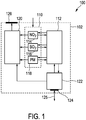
- Fig. 1 shows a schematic block diagram of an embodiment of an inhaler control clip 100.
- the inhaler control clip 100 comprises a casing 102 with a receptacle for accommodating an inhaler that is an external device with respect to the inhaler control clip 100.
- the receptacle is not shown in Fig. 1 , but will be shown in further examples in Fig. 2a and 2b .
- An inhalant in the inhaler that can be inserted into the inhaler control clip 100 is for example a medical inhalant for long-term medication of a user, e.g., for use as an asthma spray containing corticosteroids.
- the inhalant is in other examples a medical inhalant for rescue medication, containing, e.g., beta-sympathomimetics.
- a sensor unit 110 in the inhaler control clip 100 is arranged in the casing 102 and in the present embodiment has three air pollution sensors 114,116 and 118.
- the number of air pollution sensors can be higher or lower, and is to be selected according to the requirements of a given application case.
- the three air pollution sensors 114,116 and 118 are configured to perform a measurement of a concentration of nitrogen dioxide NO 2 , sulphur dioxide SO 2 and fine dust PM, respectively, in an ambient atmosphere.
- Each of the air pollution sensors 114, 116, 118 provides a respective sensor output signal.
- the sensor unit 110 is connected to a control unit 112, which is configured to trigger the sensor unit to perform the measurement at a plurality of sampling points in time within a configurable threshold time span.
- the control unit 112 also receives the sensor output signals from the sensor unit 110.
- a communication unit 122 has a communication interface 124 is included in the casing 102 of the inhaler control clip 100.
- the communication unit 122 receives, via the communication interface 124, configuration data from an external configuration device (not shown in Fig. 1 ), as indicated by an incoming direction of double arrow 125.
- the configuration data are indicative of sampling points in time to trigger performance of the measurement.
- the configuration data can provide the sampling points in time, hereinafter also called sampling times, in different ways.
- the configuration data is indicative of a time span between sampling times, or of a sampling frequency.
- the configuration data comprises reference values for the gas components nitrogen dioxide NO 2 , sulphur dioxide SO 2 and for fine dust PM concentration.
- An exemplary reference value for NO 2 is 40 ppb and an exemplary reference value for SO 2 is 20 ppb.
- An exemplary reference value for fine dust of a size falling under the PM 10 classification is 20 ⁇ g/m 3 .
- the communication unit 122 forwards the received configuration data to the control unit 112.
- the warning unit 120 receives the reference values and the sensor output signals.
- the warning unit compares the sensor unit output signals to the respective reference values. If the respective sensor unit output signal exceeds an associated respective reference value, a warning signal is generated and provided by the warning unit 120.
- the warning unit 120 transmits the warning signal to a light emitting unit 126.
- Light emitted by the light emitting unit 126 indicates an ambient atmosphere having air pollutant concentrations falling below the reference values with a green light and an ambient atmosphere having air pollutant concentrations higher than the reference values with a red light.
- control unit 112 triggers the communication unit 122 to perform a configuration exchange sequence with an external configuration device (not shown in Fig. 1 ), as indicated by the double arrow 125 in Fig. 1 .
- the configuration exchange sequence comprises forwarding the sensor output signals of the individual air pollution sensors to the external configuration device, and receiving in response updated configuration data from the external configuration device.
- the updated configuration data for instance comprises an updated frequency of sampling points in time, determined by the external configuration device using the sensor output signals of the respective air pollution sensors received from the inhaler control clip 100.
- the warning unit 120 additionally provides a warning signal, if the sensor unit output signal exceeds the reference value at all the sampling points in time within a threshold time span.
- the warning signal is provided when the sensor unit output signal of the NO 2 sensor indicates concentrations having exceeded a reference value of 10 ppb for a minimum of 60 minutes, which forms the threshold time span.
- the warning signal is provided, when the sensor unit output signal of the NO 2 sensor indicates that the concentration has exceeded 20 ppb for a minimum of 15 minutes and the sensor unit output signal of the SO 2 sensor indicates that the concentration has exceeded 10 ppb for the same reference time span of 15 minutes.
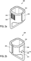
- Fig. 2a and b show two perspective views of another embodiment of an inhaler control clip 200 from two sides.
- Fig. 2c shows a perspective view of the inhaler control clip of Figs. 2a and 2b with an inserted inhaler 204 having a mouthpiece 206.
- the inhaler control clip 200 has a casing 202 for accommodating an inhaler.
- the casing 202 of the inhaler control clip 200 has a clamp shape and is made of a material with suitable elastic properties to resiliently clamp an inhaler 204 inside the casing 202.
- suitable elastic properties for resiliently clamp an inhaler 204 inside the casing 202.
- certain plastics are suitable materials.
- Fixation of the inhaler 204 inside the inhaler control clip 200 may also be achieved by providing a form-fit that removably locks the inhaler 204 inside the inhaler control clip in an inserted state.
- the inhaler control clip 200 has two air pollution sensors, not shown here, inside the casing 202.
- the air pollution sensors measure different gas components in ambient atmosphere, for example NO 2 and SO 2 .
- Openings 208 and 210 in the casing 202 formed by a plurality of slits are arranged allow access of the ambient atmosphere to the air pollution sensors.
- the inhaler control clip 200 comprises, inside the casing 202 and therefore not visible in Figs. 2a and 2b , a sensor unit, a control unit and a communication unit, whose functionality corresponds to the one of the exemplary inhaler control clip 100, inside the casing 202.
- a warning unit comprising a LED 212 is arranged on the casing 202. The LED has the same functionality as the light emitting unit of the exemplary inhaler control clip 100.
- a display 214 is arranged on one side surface 219 of the inhaler control clip 200.
- the display 214 additionally to the LED 212, displays measurement information generated by the air pollution sensors.
- the display is configured to provide a graphical representation indicating that the sensor unit output signal of nitrogen dioxide NO 2 , sulphur dioxide SO 2 or fine dust PM is exceeding the respective reference value.
- Such display can also provide information which of the individual reference values is exceeded.
- buttons 216 and 218 are arranged for actuation by the user of the inhaler control clip 200. Actuation of the control button 216 triggers the sensor unit to perform the measurement. Actuation of the control button 218 changes between display view modes, for example between a warning display shown current warning signals, and sensor signal display of either NO 2 or SO 2 or battery status.
- Fig. 3 shows a schematic block diagram of an embodiment of an inhaler control arrangement 300.
- the inhaler control arrangement 300 is used to support the monitoring of potential health risks, for example of an asthma patient.
- the inhaler control arrangement 300 comprises the inhaler control clip 100 of Fig. 1 and a configuration device 310.
- a description of the inhaler control clip 100 reference is made to the description of Fig. 1 hereinabove.
- the following description focusses on the configuration device 310.
- the configuration device 310 comprises a configuration communication interface 312 and an evaluation unit 314.
- the configuration device 310 in for example implemented as a software application that is executable by a portable computer such as smart phone.
- the software application (app) is designed to allow the smart phone receiving and evaluating the sensor output signals, i.e., implement the communication interface 312 and the evaluation 314.
- configuration data to be used by the inhaler control clip is updated.
- the configuration device 310 is connected via its configuration communication interface 312 to the communication unit 122 of the inhaler control clip 100.
- the updated configuration data is provided via the configuration communication interface to the communication unit 122.
- the evaluation unit 314 assigns the incoming sensor output signals with time stamps and determines and stores a pollution profile indicative of the concentration of the measured gas components or particulates, for example nitrogen dioxide NO 2 and sulphur dioxide SO 2 .
- the updated configuration data can be determining in dependence on the pollution profile.
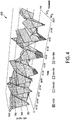
- Fig. 4 shows an exemplarily pollution profile 400 determined by the evaluation unit 314.
- the pollution profile 400 is plotted in a three dimensional coordinate system.
- the x-axis indicates the time over a time span of 24 hours.
- the y-axis indicates the concentration of the individual pollutants in units of ppb for NO 2 and SO 2 and in units of mg/m 3 for PM.
- the concentration values of the individual pollutants, here NO 2 , SO 2 and PM are plotted for the respective sampling times at different z-axis positions. In this exemplary embodiment, one sampling point is plotted per hour.
- the pollution profile uses different colors or other graphical distinctions for classifying the concentration values into different concentration intervals, based on predetermined reference values.
- the pollution profile 400 is used for complex analysis of the sensor output signals. For example, structures of specific parts in the pollution profile can be extracted and used as a search template for similar structures. These structures in the pollution profile can be, for instance, correlated with a potential health risk for the user of the inhaler control clip. Thus, the complex analysis of the pollution profile can be used for treatment or future prevention measures.
- an inhaler control clip comprises a sensor unit with an air pollution sensor, which measures at least one quantity indicative of a concentration of a gas component or particulate in an ambient atmosphere.
- a control unit triggers the sensor unit to perform the measurement.
- a communication unit has a communication interface to an external configuration device, and receives configuration data indicative sampling points in time to trigger performance of the measurement, and of at least one reference value for ambient atmosphere composition.
- the control unit receives the configuration data and is configured to trigger performance of the measurement at configurable sampling points in time using the configuration data.
- a warning unit receives the sensor output signal and the reference value and compares the sensor output signal with the reference value, and provides a warning signal upon determining that the concentration of the gas component or particulate exceeds the reference value.
Landscapes
- Health & Medical Sciences (AREA)
- Engineering & Computer Science (AREA)
- Public Health (AREA)
- General Health & Medical Sciences (AREA)
- Biomedical Technology (AREA)
- Medical Informatics (AREA)
- Primary Health Care (AREA)
- Epidemiology (AREA)
- Bioinformatics & Cheminformatics (AREA)
- General Business, Economics & Management (AREA)
- Pulmonology (AREA)
- Business, Economics & Management (AREA)
- Databases & Information Systems (AREA)
- Chemical & Material Sciences (AREA)
- Data Mining & Analysis (AREA)
- Medicinal Chemistry (AREA)
- Pathology (AREA)
- Anesthesiology (AREA)
- Heart & Thoracic Surgery (AREA)
- Hematology (AREA)
- Life Sciences & Earth Sciences (AREA)
- Animal Behavior & Ethology (AREA)
- Veterinary Medicine (AREA)
- Measuring And Recording Apparatus For Diagnosis (AREA)
Claims (14)
- Inhalatorsteuerclip (100, 200) aufweisend- ein Gehäuse (102) aufweisend eine Aufnahme zum Aufnehmen eines Inhalators;- eine Sensoreinheit (110), die in dem Gehäuse angeordnet ist und wenigstens einen Luftverschmutzungssensor (114, 116, 118) aufweist, der ausgebildet ist, eine Messung von wenigstens einer Größe durchzuführen, die indikativ für eine Konzentration wenigstens einer Gaskomponente oder Partikel in einer Umgebungsatmosphäre ist, und wenigstens ein diese anzeigendes Sensorausgangssignal bereitzustellen;- eine Steuereinheit (112), die in dem Gehäuse (102) angeordnet, mit der Sensoreinheit verbunden und ausgebildet ist, die Sensoreinheit (110) dazu zu veranlassen, die Messung durchzuführen;- eine Kommunikationseinheit (112), die in dem Gehäuse angeordnet ist und eine Kommunikationsschnittstelle (124) zu einem externen Konfigurationsgerät aufweist, und die ausgebildet ist, über die Kommunikationsschnittstelle Konfigurationsdaten zu empfangen, die indikativ sind für einen oder mehrere Abtastzeitpunkte, um ein Durchführen der Messung und zu veranlassen, und für wenigstens einen Referenzwert für eine Umgebungsatmosphärenzusammensetzung; und- eine Warneinheit (120), die in dem Gehäuse (102) angeordnet und ausgebildet ist, das Sensorausgangssignal und den Referenzwert zu empfangen und das Sensorausgangssignal mit dem Referenzwert zu vergleichen und ein Warnsignal bereitzustellen, falls ermittelt wird, dass die Konzentration der wenigstens einen Gaskomponente oder Partikel in der Umgebungsatmosphäre den Referenzwert übersteigt; wobei- die Steuereinheit (112) die Konfigurationsdaten empfängt und ausgebildet ist, die Konfigurationsdaten zu verwenden, um ein Durchführen der Messung zu konfigurierbaren Abtastzeitpunkten zu veranlassen.
- Inhalatorsteuerclip (100, 200) gemäß Anspruch 1, wobei- die Steuereinheit (112) ausgebildet ist, die Sensoreinheit dazu zu veranlassen, die Messung zu einer Vielzahl von Abtastzeitpunkten innerhalb einer konfigurierbaren Schwellenwertzeitspanne durchzuführen; und wobei- die Warneinheit (120) ausgebildet ist, das Warnsignal bereitzustellen, falls ermittelt wird, dass die Konzentration der wenigstens einen Gaskomponente oder Partikel in der Umgebungsatmosphäre den Referenzwert an allen der Abstastzeitpunkte innerhalb der Schwellenwertzeitspanne übersteigt.
- Inhalatorsteuerclip (100, 200) gemäß Anspruch 1 oder 2, wobei- die Kommunikationseinheit (122) ausgebildet ist, über die Kommunikationsschnittstelle (124) eine Vielzahl von Referenzwerten für die Umgebungsatmosphärenzusammensetzung zu empfangen, die unterschiedlichen Gaskomponenten oder Partikeln in der Umgebungsatmosphäre zugeordnet sind;- die Warneinheit (120) ausgebildet ist, das Warnsignal bereitzustellen, falls ermittelt wird, dass eine Kombination aus wenigstens zwei Referenzwerten durch die Konzentration der wenigstens einen Gaskomponente oder Partikel in der Umgebungsatmosphäre überstiegen wird.
- Inhalatorsteuerclip (100, 200) gemäß einem der vorstehenden Ansprüche, wobei der Luftverschmutzungssensor (114, 116, 118) ausgebildet ist, eine Messung von einer Größe durchzuführen, die indikativ für eine Konzentration von Stickstoffdioxid oder Schwefeldioxid ist.
- Inhalatorsteuerclip (100, 200) gemäß einem der vorstehenden Ansprüche, weiterhin aufweisend wenigstens einen Umgebungssensor, der ausgebildet ist, eine Messung von wenigstens einer Größe durchzuführen, die indikativ für eine Temperatur der Umgebungsatmosphäre, eine relative Feuchtigkeit der Umgebungsatmosphäre oder eines Druckes der Umgebungsatmosphäre ist.
- Inhalatorsteuerclip (100, 200) gemäß einem der vorstehenden Ansprüche, weiterhin aufweisend eine Anzeige (214), die das Warnsignal empfängt und ausgebildet ist, nach Empfang des Warnsignals, eine graphische Darstellung bereitzustellen, die angibt, dass die Konzentration der wenigstens einen Gaskomponente oder Partikel in der Umgebungsatmosphäre den Referenzwert übersteigt.
- Inhalatorsteuerclip (100, 200) gemäß einem dervorstehenden Ansprüche, wobei die Warneinheit eine Lichtemissionseinheit (126, 212) aufweist, die ausgebildet ist, das Warnsignal als ein Lichtsignal in einer jeweiligen von einer Vielzahl unterschiedlicher Lichtfarben zu emittieren, und eine Menge der gemessenen Konzentration der wenigstens einer Gaskomponente oder Partikel in der Umgebungsatmosphäre zu verwenden, um die zu emittierenden Lichtfarbe zu bestimmen.
- Inhalatorsteuerclip (100, 200) gemäß einem der vorstehenden Ansprüche, wobei- die Steuereinheit (112) ausgebildet ist, die Kommunikationseinheit (122) dazu zu veranlassen, eine Konfigurationsaustauschabfolge (125) mit dem externen Konfigurationsgerät durchzuführen, wobei die Konfigurationsaustauschabfolge (125) ein Weiterleiten des Sensorausgangssignals an das externe Konfigurationsgerät und, in Antwort darauf, ein Empfangen aktualisierter Konfigurationsdaten von dem externen Konfigurationsgerät umfasst, und wobei- die Kommunikationseinheit (122) ausgebildet ist, die Konfigurationsaustauschabfolge durchzuführen und die aktualisierten Konfigurationsdaten an die Steuereinheit (112) weiterzuleiten.
- Inhalatorsteuerclip (100, 200) gemäß Anspruch 8, weiterhin aufweisend- eine Scaneinheit, die ausgebildet ist, einen Oberflächenabschnitt eines Behälters zu scannen, um einen graphischen Code zu erfassen, der eine Art von Arzneimittel in dem Aufbewahrungsbehälter kennzeichnet und ein dieses anzeigendes Scaneinheitausgangssignal bereitzustellen;wobei die Konfigurationsaustauschabfolge weiterhin ein Bereitstellen des Scaneinheitausgangssignals an das externe Konfigurationsgerät umfasst.
- Inhalatorsteuerclip (100, 200) gemäß Anspruch 6, wobei die Kommunikationseinheit (122) weiterhin ausgebildet ist, über die Kommunikationsschnittstelle Arzneimittelempfehlungsdaten zu empfangen, die für eine empfohlene Arzneimitteldosis indikativ sind, und die Arzneimittelempfehlungsdaten an die Anzeige zur Ausgabe an einen Nutzer bereitzustellen.
- Inhalatorsteuerclip (100, 200) gemäß einem der vorstehenden Ansprüche, weiterhin aufweisend einen Betätigungssensor, der ausgebildet ist, ein Betätigen eines Inhalationsbetätigungselements an einem externen Inhalator (204) in einem eingesetzten Zustand zu erfassen und ein diese anzeigendes Betätigungssignal bereitzustellen, wobei die Steuereinheit (112) ausgebildet ist, nach Empfang des Betätigungssignals die Sensoreinheit (110) dazu zu veranlassen die Messung durchzuführen.
- Inhalatorsteueranordnung (300) aufweisend- wenigstes einen Inhalatorsteuerclip (100) gemäß Anspruch 1;- ein Konfigurationsgerät (310), das mit der Kommunikationseinheit (122) des Inhalatorsteuerclips (100) kommunizierend verbindbar ist und aufweist- eine Konfigurationskommunikationsschnittstelle (312), die ausgebildet ist, eines oder mehrere Sensorausgangssignale von der Kommunikationseinheit (122) des Inhalatorsteuerclips (100) zu empfangen und aktualisierte Konfigurationsdaten an die Kommunikationseinheit (122) des Inhalatorsteuerclips bereitzustellen;- eine Auswerteeinheit (314), die ausgebildet ist, das eine oder die mehreren empfangenen Sensorsignale dazu zu verwenden, von dem Inhalatorsteuerclip (100) zu verwendende aktualisierte Konfigurationsdaten zu bestimmen und die aktualisierten Konfigurationsdaten der Konfigurationskommunikationsschnittstelle (312) bereitzustellen.
- Inhalatorsteueranordnung (300) gemäß Anspruch 12, wobei die Auswerteeinheit (314) des Konfigurationsgeräts (310) ausgebildet ist- eintreffenden Sensorausgangssignalen Zeitstempel zuzuweisen und während einer vorbestimmten Überwachungszeitspanne ein Luftverschmutzungsprofil (400) als Funktion der Zeit zu bestimmen und zu speichern, das indikativ für eine Konzentration wenigstens einer Gaskomponente oder Partikel in der Umgebungsatmosphäre ist.
- Inhalatorsteueranordnung (300) gemäß Anspruch 13, wobei die Auswerteeinheit (314) des Konfigurationsgeräts (310) ausgebildet ist, die aktualisierten Konfigurationsdaten in Abhängigkeit von dem Luftverschmutzungsprofil (400) zu bestimmen.
Priority Applications (1)
| Application Number | Priority Date | Filing Date | Title |
|---|---|---|---|
| PCT/EP2019/086648 WO2020127952A1 (en) | 2018-12-21 | 2019-12-20 | Inhaler and inhaler control arrangement |
Applications Claiming Priority (1)
| Application Number | Priority Date | Filing Date | Title |
|---|---|---|---|
| EP18215509 | 2018-12-21 |
Publications (2)
| Publication Number | Publication Date |
|---|---|
| EP3669915A1 EP3669915A1 (de) | 2020-06-24 |
| EP3669915B1 true EP3669915B1 (de) | 2021-08-11 |
Family
ID=65023654
Family Applications (1)
| Application Number | Title | Priority Date | Filing Date |
|---|---|---|---|
| EP19156518.3A Active EP3669915B1 (de) | 2018-12-21 | 2019-02-11 | Inhalatorsteuerungsclip und inhalatorsteuerungsanordnung |
Country Status (2)
| Country | Link |
|---|---|
| EP (1) | EP3669915B1 (de) |
| WO (1) | WO2020127952A1 (de) |
Families Citing this family (1)
| Publication number | Priority date | Publication date | Assignee | Title |
|---|---|---|---|---|
| DE102020214411A1 (de) | 2020-11-17 | 2022-05-19 | Robert Bosch Gesellschaft mit beschränkter Haftung | Adaptionsvorrichtung für einen Inhalator, Sensormodul, Verfahren zum Versehen eines Inhalators mit Informationen und Verfahren zum Betreiben eines Sensormoduls |
Family Cites Families (3)
| Publication number | Priority date | Publication date | Assignee | Title |
|---|---|---|---|---|
| WO2015109259A1 (en) * | 2014-01-16 | 2015-07-23 | Focusstart Respiratory Llc | Systems and methods for managing pulmonary medication delivery |
| EP3053620A3 (de) * | 2015-02-04 | 2016-10-26 | Anandhakrishnan Vaidyanathan | Intelligentes inhalatorhalfter mit einem system und verfahren zum abtasten und verfolgen von eigenschaften eingeatmeter luft und medikation, zum warnen in ungünstigen umgebungen, zum abbilden einer medikation mit persönlicher dynamik, eingeatmeter luft und umgebung für bessere gesundheit |
| DE102016219759A1 (de) | 2016-07-22 | 2018-01-25 | Centre for Research and Technology Hellas - InformationTechnologies Institute (CERTH/ITI) | Sensoreinheit für einen Inhalator, Inhalator, sowie Überwachungsanordnung |
-
2019
- 2019-02-11 EP EP19156518.3A patent/EP3669915B1/de active Active
- 2019-12-20 WO PCT/EP2019/086648 patent/WO2020127952A1/en active Application Filing
Also Published As
| Publication number | Publication date |
|---|---|
| EP3669915A1 (de) | 2020-06-24 |
| WO2020127952A1 (en) | 2020-06-25 |
Similar Documents
| Publication | Publication Date | Title |
|---|---|---|
| US11241594B2 (en) | Face mask for filtering air and air monitoring system | |
| US20210223221A1 (en) | Gas Measurement Device Incorporated Into a Watch | |
| US9858794B2 (en) | Detecting and notifying of various potential hazards | |
| US8031074B2 (en) | Personal emergency notification device with usage monitoring | |
| US7688198B2 (en) | Apparatus and method for monitoring hazardous materials in a processing or other environment | |
| KR101484581B1 (ko) | 상호작용형 알콜측정 | |
| US20050001728A1 (en) | Equipment and method for identifying, monitoring and evaluating equipment, environmental and physiological conditions | |
| US8103459B2 (en) | Safety clothing | |
| KR101755533B1 (ko) | 사물인터넷 기반 안전 관리 시스템 | |
| KR101517332B1 (ko) | 공기정보 제공 시스템 | |
| WO2013066316A1 (en) | Detection of gas mixtures having an additive or synergistic toxic effect | |
| CN107249694B (zh) | 呼吸面罩管理系统 | |
| US20150153061A1 (en) | Method for controlling and monitoring the level of confinement of internal air, and related environment device and station | |
| US20200007741A1 (en) | Detection system and method | |
| KR101901272B1 (ko) | 대기 환경 측정 시스템 | |
| EP3669915B1 (de) | Inhalatorsteuerungsclip und inhalatorsteuerungsanordnung | |
| KR101694606B1 (ko) | 사용자 모니터링을 위한 착용형 장치 및 시스템 | |
| KR102445730B1 (ko) | 공기청정도 데이터 공유 서비스 시스템 및 공기청정도 데이터를 표시하는 모바일 전자기기 | |
| KR102655514B1 (ko) | 아동 시트 검사 시스템 및 아동 시트 검사 방법 | |
| CN109313839A (zh) | 集成热生理应力警告装置 | |
| CN108107158A (zh) | 一种空气检测系统及其检测方法 | |
| KR20170033495A (ko) | 특정 단말기를 이용한 사용자 맞춤형 서비스 제공 시스템 및 그 방법 | |
| KR101936081B1 (ko) | 대기오염 정보와 기상정보를 활용한 스마트 대기정보 측정 장치 와 그 방법 | |
| KR101783003B1 (ko) | 안전 밴드를 활용한 안전 관리 시스템 및 이의 동작 방법 | |
| CN110298987A (zh) | 服务器及火灾逃生方法 |
Legal Events
| Date | Code | Title | Description |
|---|---|---|---|
| PUAI | Public reference made under article 153(3) epc to a published international application that has entered the european phase |
Free format text: ORIGINAL CODE: 0009012 |
|
| STAA | Information on the status of an ep patent application or granted ep patent |
Free format text: STATUS: THE APPLICATION HAS BEEN PUBLISHED |
|
| AK | Designated contracting states |
Kind code of ref document: A1 Designated state(s): AL AT BE BG CH CY CZ DE DK EE ES FI FR GB GR HR HU IE IS IT LI LT LU LV MC MK MT NL NO PL PT RO RS SE SI SK SM TR |
|
| AX | Request for extension of the european patent |
Extension state: BA ME |
|
| STAA | Information on the status of an ep patent application or granted ep patent |
Free format text: STATUS: REQUEST FOR EXAMINATION WAS MADE |
|
| 17P | Request for examination filed |
Effective date: 20201027 |
|
| RBV | Designated contracting states (corrected) |
Designated state(s): AL AT BE BG CH CY CZ DE DK EE ES FI FR GB GR HR HU IE IS IT LI LT LU LV MC MK MT NL NO PL PT RO RS SE SI SK SM TR |
|
| GRAP | Despatch of communication of intention to grant a patent |
Free format text: ORIGINAL CODE: EPIDOSNIGR1 |
|
| STAA | Information on the status of an ep patent application or granted ep patent |
Free format text: STATUS: GRANT OF PATENT IS INTENDED |
|
| INTG | Intention to grant announced |
Effective date: 20210224 |
|
| GRAS | Grant fee paid |
Free format text: ORIGINAL CODE: EPIDOSNIGR3 |
|
| GRAA | (expected) grant |
Free format text: ORIGINAL CODE: 0009210 |
|
| STAA | Information on the status of an ep patent application or granted ep patent |
Free format text: STATUS: THE PATENT HAS BEEN GRANTED |
|
| AK | Designated contracting states |
Kind code of ref document: B1 Designated state(s): AL AT BE BG CH CY CZ DE DK EE ES FI FR GB GR HR HU IE IS IT LI LT LU LV MC MK MT NL NO PL PT RO RS SE SI SK SM TR |
|
| REG | Reference to a national code |
Ref country code: CH Ref legal event code: EP |
|
| REG | Reference to a national code |
Ref country code: DE Ref legal event code: R096 Ref document number: 602019006689 Country of ref document: DE |
|
| REG | Reference to a national code |
Ref country code: IE Ref legal event code: FG4D Ref country code: AT Ref legal event code: REF Ref document number: 1418732 Country of ref document: AT Kind code of ref document: T Effective date: 20210915 |
|
| REG | Reference to a national code |
Ref country code: LT Ref legal event code: MG9D |
|
| REG | Reference to a national code |
Ref country code: NL Ref legal event code: MP Effective date: 20210811 |
|
| REG | Reference to a national code |
Ref country code: AT Ref legal event code: MK05 Ref document number: 1418732 Country of ref document: AT Kind code of ref document: T Effective date: 20210811 |
|
| PG25 | Lapsed in a contracting state [announced via postgrant information from national office to epo] |
Ref country code: SE Free format text: LAPSE BECAUSE OF FAILURE TO SUBMIT A TRANSLATION OF THE DESCRIPTION OR TO PAY THE FEE WITHIN THE PRESCRIBED TIME-LIMIT Effective date: 20210811 Ref country code: RS Free format text: LAPSE BECAUSE OF FAILURE TO SUBMIT A TRANSLATION OF THE DESCRIPTION OR TO PAY THE FEE WITHIN THE PRESCRIBED TIME-LIMIT Effective date: 20210811 Ref country code: ES Free format text: LAPSE BECAUSE OF FAILURE TO SUBMIT A TRANSLATION OF THE DESCRIPTION OR TO PAY THE FEE WITHIN THE PRESCRIBED TIME-LIMIT Effective date: 20210811 Ref country code: FI Free format text: LAPSE BECAUSE OF FAILURE TO SUBMIT A TRANSLATION OF THE DESCRIPTION OR TO PAY THE FEE WITHIN THE PRESCRIBED TIME-LIMIT Effective date: 20210811 Ref country code: HR Free format text: LAPSE BECAUSE OF FAILURE TO SUBMIT A TRANSLATION OF THE DESCRIPTION OR TO PAY THE FEE WITHIN THE PRESCRIBED TIME-LIMIT Effective date: 20210811 Ref country code: PT Free format text: LAPSE BECAUSE OF FAILURE TO SUBMIT A TRANSLATION OF THE DESCRIPTION OR TO PAY THE FEE WITHIN THE PRESCRIBED TIME-LIMIT Effective date: 20211213 Ref country code: NO Free format text: LAPSE BECAUSE OF FAILURE TO SUBMIT A TRANSLATION OF THE DESCRIPTION OR TO PAY THE FEE WITHIN THE PRESCRIBED TIME-LIMIT Effective date: 20211111 Ref country code: LT Free format text: LAPSE BECAUSE OF FAILURE TO SUBMIT A TRANSLATION OF THE DESCRIPTION OR TO PAY THE FEE WITHIN THE PRESCRIBED TIME-LIMIT Effective date: 20210811 Ref country code: BG Free format text: LAPSE BECAUSE OF FAILURE TO SUBMIT A TRANSLATION OF THE DESCRIPTION OR TO PAY THE FEE WITHIN THE PRESCRIBED TIME-LIMIT Effective date: 20211111 Ref country code: AT Free format text: LAPSE BECAUSE OF FAILURE TO SUBMIT A TRANSLATION OF THE DESCRIPTION OR TO PAY THE FEE WITHIN THE PRESCRIBED TIME-LIMIT Effective date: 20210811 |
|
| PG25 | Lapsed in a contracting state [announced via postgrant information from national office to epo] |
Ref country code: PL Free format text: LAPSE BECAUSE OF FAILURE TO SUBMIT A TRANSLATION OF THE DESCRIPTION OR TO PAY THE FEE WITHIN THE PRESCRIBED TIME-LIMIT Effective date: 20210811 Ref country code: LV Free format text: LAPSE BECAUSE OF FAILURE TO SUBMIT A TRANSLATION OF THE DESCRIPTION OR TO PAY THE FEE WITHIN THE PRESCRIBED TIME-LIMIT Effective date: 20210811 Ref country code: GR Free format text: LAPSE BECAUSE OF FAILURE TO SUBMIT A TRANSLATION OF THE DESCRIPTION OR TO PAY THE FEE WITHIN THE PRESCRIBED TIME-LIMIT Effective date: 20211112 |
|
| PG25 | Lapsed in a contracting state [announced via postgrant information from national office to epo] |
Ref country code: NL Free format text: LAPSE BECAUSE OF FAILURE TO SUBMIT A TRANSLATION OF THE DESCRIPTION OR TO PAY THE FEE WITHIN THE PRESCRIBED TIME-LIMIT Effective date: 20210811 |
|
| PG25 | Lapsed in a contracting state [announced via postgrant information from national office to epo] |
Ref country code: DK Free format text: LAPSE BECAUSE OF FAILURE TO SUBMIT A TRANSLATION OF THE DESCRIPTION OR TO PAY THE FEE WITHIN THE PRESCRIBED TIME-LIMIT Effective date: 20210811 |
|
| REG | Reference to a national code |
Ref country code: DE Ref legal event code: R097 Ref document number: 602019006689 Country of ref document: DE |
|
| PG25 | Lapsed in a contracting state [announced via postgrant information from national office to epo] |
Ref country code: SM Free format text: LAPSE BECAUSE OF FAILURE TO SUBMIT A TRANSLATION OF THE DESCRIPTION OR TO PAY THE FEE WITHIN THE PRESCRIBED TIME-LIMIT Effective date: 20210811 Ref country code: SK Free format text: LAPSE BECAUSE OF FAILURE TO SUBMIT A TRANSLATION OF THE DESCRIPTION OR TO PAY THE FEE WITHIN THE PRESCRIBED TIME-LIMIT Effective date: 20210811 Ref country code: RO Free format text: LAPSE BECAUSE OF FAILURE TO SUBMIT A TRANSLATION OF THE DESCRIPTION OR TO PAY THE FEE WITHIN THE PRESCRIBED TIME-LIMIT Effective date: 20210811 Ref country code: EE Free format text: LAPSE BECAUSE OF FAILURE TO SUBMIT A TRANSLATION OF THE DESCRIPTION OR TO PAY THE FEE WITHIN THE PRESCRIBED TIME-LIMIT Effective date: 20210811 Ref country code: CZ Free format text: LAPSE BECAUSE OF FAILURE TO SUBMIT A TRANSLATION OF THE DESCRIPTION OR TO PAY THE FEE WITHIN THE PRESCRIBED TIME-LIMIT Effective date: 20210811 Ref country code: AL Free format text: LAPSE BECAUSE OF FAILURE TO SUBMIT A TRANSLATION OF THE DESCRIPTION OR TO PAY THE FEE WITHIN THE PRESCRIBED TIME-LIMIT Effective date: 20210811 |
|
| PLBE | No opposition filed within time limit |
Free format text: ORIGINAL CODE: 0009261 |
|
| STAA | Information on the status of an ep patent application or granted ep patent |
Free format text: STATUS: NO OPPOSITION FILED WITHIN TIME LIMIT |
|
| 26N | No opposition filed |
Effective date: 20220512 |
|
| PG25 | Lapsed in a contracting state [announced via postgrant information from national office to epo] |
Ref country code: IT Free format text: LAPSE BECAUSE OF FAILURE TO SUBMIT A TRANSLATION OF THE DESCRIPTION OR TO PAY THE FEE WITHIN THE PRESCRIBED TIME-LIMIT Effective date: 20210811 |
|
| PG25 | Lapsed in a contracting state [announced via postgrant information from national office to epo] |
Ref country code: SI Free format text: LAPSE BECAUSE OF FAILURE TO SUBMIT A TRANSLATION OF THE DESCRIPTION OR TO PAY THE FEE WITHIN THE PRESCRIBED TIME-LIMIT Effective date: 20210811 |
|
| PG25 | Lapsed in a contracting state [announced via postgrant information from national office to epo] |
Ref country code: MC Free format text: LAPSE BECAUSE OF FAILURE TO SUBMIT A TRANSLATION OF THE DESCRIPTION OR TO PAY THE FEE WITHIN THE PRESCRIBED TIME-LIMIT Effective date: 20210811 |
|
| REG | Reference to a national code |
Ref country code: CH Ref legal event code: PL |
|
| REG | Reference to a national code |
Ref country code: BE Ref legal event code: MM Effective date: 20220228 |
|
| PG25 | Lapsed in a contracting state [announced via postgrant information from national office to epo] |
Ref country code: LU Free format text: LAPSE BECAUSE OF NON-PAYMENT OF DUE FEES Effective date: 20220211 |
|
| PG25 | Lapsed in a contracting state [announced via postgrant information from national office to epo] |
Ref country code: LI Free format text: LAPSE BECAUSE OF NON-PAYMENT OF DUE FEES Effective date: 20220228 Ref country code: IE Free format text: LAPSE BECAUSE OF NON-PAYMENT OF DUE FEES Effective date: 20220211 Ref country code: CH Free format text: LAPSE BECAUSE OF NON-PAYMENT OF DUE FEES Effective date: 20220228 |
|
| PG25 | Lapsed in a contracting state [announced via postgrant information from national office to epo] |
Ref country code: BE Free format text: LAPSE BECAUSE OF NON-PAYMENT OF DUE FEES Effective date: 20220228 |
|
| PGFP | Annual fee paid to national office [announced via postgrant information from national office to epo] |
Ref country code: FR Payment date: 20230227 Year of fee payment: 5 |
|
| PGFP | Annual fee paid to national office [announced via postgrant information from national office to epo] |
Ref country code: GB Payment date: 20230227 Year of fee payment: 5 Ref country code: DE Payment date: 20230308 Year of fee payment: 5 |