EP3669799B1 - Embolie-spulen-fördervorrichtung und herstellungsverfahren dafür - Google Patents
Embolie-spulen-fördervorrichtung und herstellungsverfahren dafür Download PDFInfo
- Publication number
- EP3669799B1 EP3669799B1 EP18847082.7A EP18847082A EP3669799B1 EP 3669799 B1 EP3669799 B1 EP 3669799B1 EP 18847082 A EP18847082 A EP 18847082A EP 3669799 B1 EP3669799 B1 EP 3669799B1
- Authority
- EP
- European Patent Office
- Prior art keywords
- embolic coil
- conductive wire
- stretch
- conveying device
- resistant thread
- Prior art date
- Legal status (The legal status is an assumption and is not a legal conclusion. Google has not performed a legal analysis and makes no representation as to the accuracy of the status listed.)
- Active
Links
Images



Classifications
-
- A—HUMAN NECESSITIES
- A61—MEDICAL OR VETERINARY SCIENCE; HYGIENE
- A61B—DIAGNOSIS; SURGERY; IDENTIFICATION
- A61B17/00—Surgical instruments, devices or methods
- A61B17/12—Surgical instruments, devices or methods for ligaturing or otherwise compressing tubular parts of the body, e.g. blood vessels or umbilical cord
- A61B17/12022—Occluding by internal devices, e.g. balloons or releasable wires
- A61B17/12131—Occluding by internal devices, e.g. balloons or releasable wires characterised by the type of occluding device
- A61B17/1214—Coils or wires
-
- A—HUMAN NECESSITIES
- A61—MEDICAL OR VETERINARY SCIENCE; HYGIENE
- A61B—DIAGNOSIS; SURGERY; IDENTIFICATION
- A61B17/00—Surgical instruments, devices or methods
- A61B17/12—Surgical instruments, devices or methods for ligaturing or otherwise compressing tubular parts of the body, e.g. blood vessels or umbilical cord
- A61B17/12022—Occluding by internal devices, e.g. balloons or releasable wires
- A61B17/12099—Occluding by internal devices, e.g. balloons or releasable wires characterised by the location of the occluder
- A61B17/12109—Occluding by internal devices, e.g. balloons or releasable wires characterised by the location of the occluder in a blood vessel
- A61B17/12113—Occluding by internal devices, e.g. balloons or releasable wires characterised by the location of the occluder in a blood vessel within an aneurysm
-
- A—HUMAN NECESSITIES
- A61—MEDICAL OR VETERINARY SCIENCE; HYGIENE
- A61B—DIAGNOSIS; SURGERY; IDENTIFICATION
- A61B17/00—Surgical instruments, devices or methods
- A61B17/12—Surgical instruments, devices or methods for ligaturing or otherwise compressing tubular parts of the body, e.g. blood vessels or umbilical cord
- A61B17/12022—Occluding by internal devices, e.g. balloons or releasable wires
- A61B17/12131—Occluding by internal devices, e.g. balloons or releasable wires characterised by the type of occluding device
- A61B17/1214—Coils or wires
- A61B17/12154—Coils or wires having stretch limiting means
-
- A—HUMAN NECESSITIES
- A61—MEDICAL OR VETERINARY SCIENCE; HYGIENE
- A61B—DIAGNOSIS; SURGERY; IDENTIFICATION
- A61B17/00—Surgical instruments, devices or methods
- A61B17/12—Surgical instruments, devices or methods for ligaturing or otherwise compressing tubular parts of the body, e.g. blood vessels or umbilical cord
- A61B17/12022—Occluding by internal devices, e.g. balloons or releasable wires
- A61B17/12027—Type of occlusion
- A61B17/12031—Type of occlusion complete occlusion
-
- A—HUMAN NECESSITIES
- A61—MEDICAL OR VETERINARY SCIENCE; HYGIENE
- A61B—DIAGNOSIS; SURGERY; IDENTIFICATION
- A61B17/00—Surgical instruments, devices or methods
- A61B17/12—Surgical instruments, devices or methods for ligaturing or otherwise compressing tubular parts of the body, e.g. blood vessels or umbilical cord
- A61B17/12022—Occluding by internal devices, e.g. balloons or releasable wires
- A61B17/12131—Occluding by internal devices, e.g. balloons or releasable wires characterised by the type of occluding device
- A61B17/1214—Coils or wires
- A61B17/12145—Coils or wires having a pre-set deployed three-dimensional shape
-
- A—HUMAN NECESSITIES
- A61—MEDICAL OR VETERINARY SCIENCE; HYGIENE
- A61M—DEVICES FOR INTRODUCING MEDIA INTO, OR ONTO, THE BODY; DEVICES FOR TRANSDUCING BODY MEDIA OR FOR TAKING MEDIA FROM THE BODY; DEVICES FOR PRODUCING OR ENDING SLEEP OR STUPOR
- A61M25/00—Catheters; Hollow probes
- A61M25/0009—Making of catheters or other medical or surgical tubes
-
- A—HUMAN NECESSITIES
- A61—MEDICAL OR VETERINARY SCIENCE; HYGIENE
- A61B—DIAGNOSIS; SURGERY; IDENTIFICATION
- A61B17/00—Surgical instruments, devices or methods
- A61B2017/00526—Methods of manufacturing
-
- A—HUMAN NECESSITIES
- A61—MEDICAL OR VETERINARY SCIENCE; HYGIENE
- A61B—DIAGNOSIS; SURGERY; IDENTIFICATION
- A61B17/00—Surgical instruments, devices or methods
- A61B2017/00831—Material properties
-
- A—HUMAN NECESSITIES
- A61—MEDICAL OR VETERINARY SCIENCE; HYGIENE
- A61B—DIAGNOSIS; SURGERY; IDENTIFICATION
- A61B17/00—Surgical instruments, devices or methods
- A61B2017/00831—Material properties
- A61B2017/00929—Material properties isolating electrical current
-
- A—HUMAN NECESSITIES
- A61—MEDICAL OR VETERINARY SCIENCE; HYGIENE
- A61B—DIAGNOSIS; SURGERY; IDENTIFICATION
- A61B17/00—Surgical instruments, devices or methods
- A61B17/12—Surgical instruments, devices or methods for ligaturing or otherwise compressing tubular parts of the body, e.g. blood vessels or umbilical cord
- A61B17/12022—Occluding by internal devices, e.g. balloons or releasable wires
- A61B2017/1205—Introduction devices
-
- A—HUMAN NECESSITIES
- A61—MEDICAL OR VETERINARY SCIENCE; HYGIENE
- A61B—DIAGNOSIS; SURGERY; IDENTIFICATION
- A61B17/00—Surgical instruments, devices or methods
- A61B17/12—Surgical instruments, devices or methods for ligaturing or otherwise compressing tubular parts of the body, e.g. blood vessels or umbilical cord
- A61B17/12022—Occluding by internal devices, e.g. balloons or releasable wires
- A61B2017/1205—Introduction devices
- A61B2017/12054—Details concerning the detachment of the occluding device from the introduction device
- A61B2017/12063—Details concerning the detachment of the occluding device from the introduction device electrolytically detachable
-
- A—HUMAN NECESSITIES
- A61—MEDICAL OR VETERINARY SCIENCE; HYGIENE
- A61B—DIAGNOSIS; SURGERY; IDENTIFICATION
- A61B17/00—Surgical instruments, devices or methods
- A61B17/12—Surgical instruments, devices or methods for ligaturing or otherwise compressing tubular parts of the body, e.g. blood vessels or umbilical cord
- A61B17/12022—Occluding by internal devices, e.g. balloons or releasable wires
- A61B2017/1205—Introduction devices
- A61B2017/12054—Details concerning the detachment of the occluding device from the introduction device
- A61B2017/1209—Details concerning the detachment of the occluding device from the introduction device detachable by electrical current or potential, e.g. electroactive polymer
-
- A—HUMAN NECESSITIES
- A61—MEDICAL OR VETERINARY SCIENCE; HYGIENE
- A61B—DIAGNOSIS; SURGERY; IDENTIFICATION
- A61B17/00—Surgical instruments, devices or methods
- A61B17/12—Surgical instruments, devices or methods for ligaturing or otherwise compressing tubular parts of the body, e.g. blood vessels or umbilical cord
- A61B17/12022—Occluding by internal devices, e.g. balloons or releasable wires
- A61B2017/1205—Introduction devices
- A61B2017/12054—Details concerning the detachment of the occluding device from the introduction device
- A61B2017/12095—Threaded connection
Definitions
- the present invention relates to the field of medical devices, and in particular, to an embolic coil conveying device and a preparation method thereof.
- intravascular interventional therapy provides new technology for the treatment of intracranial aneurysms, especially since the advent of embolic coils which has greatly improved the safety and efficacy of intravascular therapy for intracranial aneurysms, and has reached or exceeded that of craniotomy.
- the embolic coil is generally detached in the cavity of the cerebral aneurysm to result in blood clots in the cavity to achieve the purpose of embolization of the arterial aneurysm.
- the embolic coils currently used mainly include mechanical detachable coils, thermolytic detachable coils, and electrolytic detachable coils.
- the most commonly used are electrolytic detachable coils, mainly including the GDCs (Guglielmi detachable coils) and Target coils from Boston Scientific.
- GDCs Guardmi detachable coils
- Target coils from Boston Scientific.
- Guglielmi detachable coils mainly including the GDCs (Guglielmi detachable coils) and Target coils from Boston Scientific.
- GDC Guardmi detachable coils
- Target coils from Boston Scientific.
- the distal end of the GDC is a platinum coil, which is connected to a stainless steel guide wire.
- the design of the embolic coil material enables the coil to reach the aneurysmal lesions of the tortuous and complicated cerebral artery.
- Embolization of the aneurysmal cavity with the GDC electrolytic detachable coil is achieved by carrying out percutaneous vascular puncture, introducing the coil into the arterial aneurysm by means of a microcatheter, fusing by electrolysis the part where the embolic coil is connected to the stainless steel guide wire, and detaching the embolic coil inside the arterial aneurysm, thereby preventing blood flowing into the arterial aneurysm.
- a more critical step in treating intracranial aneurysms with embolic coils is that: the microcatheter is accurately put in place and can be kept at the neck of the aneurysmal cavity, the terminal end of the microcatheter is kept in the aneurysmal cavity 1/3 to 1/2 away from the aneurysmal neck, or at the aneurysmal neck in smaller arterial aneurysms. In this way, the resistance is small, and it is conducive to the winding of the embolic coil.
- the significant problem of the GDC and Target coils produced by Boston Scientific, the Axium coils produced by Medtronic (Ev3), and the MicroPlex and HydroCoil coils produced by Microvention is that: the detachment section between the coil and the pusher (the detachment section refers to a section where the embolic coil and the pusher are connected, and the detachment point that is disconnected by means of electrolysis is located in this section.
- the detachment section is not equal to the detachment point, but refers to a section starting from the point of sudden softness change at the distal end of the pusher to the point of sudden softness change at the proximal end of the coil) is relatively long (at least greater than 1.5 mm, some even up to 3 mm), and stiff (the bending modulus of elasticity is at least greater than 300 MPa) .
- an anchoring spring and Polyethylene Terephthalate (PET) tube are disposed between a coil and a pusher of the GDC coil, and the length of the detachment section is 1.6 mm.
- a heating spring, a support spring, PET tube and a conductive wire of the MicroPlex coil make the length of the detachment section 3.0 mm.
- the length of the occlusal detachment section of the PET, a hypotube and a ball of the Axium coil is 2.0 mm.
- the kick-out effect causes the microcatheter to be displaced, which will inevitably require the relocation of the microcatheter in the aneurysmal cavity near the aneurysmal neck by the surgeon.
- the previously-filled coils block the channel, which makes it difficult for the surgeon to relocate the microcatheter, prolonging the operation time or causing surgical failure.
- An anchoring module is disposed between a delivery guide wire and a coil of the mechanical detachable coil.
- a heating module is disposed between a pusher and a coil of the thermolytic detachable coil.
- an insulating module is disposed between a delivery guide wire and a coil of the existing electrolytic detachable coil.
- US 6 165 178 A discloses an implant assembly in which an implant is placed in the human body using an electrolytically severable joint, wherein a core wire is attached to the implant such that the implant may be electrolytically detached by application of a current to the core wire.
- the implant is a helically wound coil having a stretch-resistant member through its center lumen according to another variation of the disclosure.
- An objective of the present invention is to provide an embolic coil conveying device and a preparation method thereof, which overcome the problem in the prior art of the kick-out of a microcatheter.
- an embolic coil conveying device including a pusher and an embolic coil, wherein a section where a distal end of the pusher and a proximal end of the embolic coil are connected is a detachment section.
- the embolic coil conveying device further includes: a stretch-resistant thread disposed in the embolic coil, the stretch-resistant thread being fixed on a ring at the proximal end of the embolic coil; and a conductive wire configured to pass through an inside of the pusher.
- the conductive wire is covered by an insulating layer and a detachment point that is not covered by the insulating layer is provided on a distal end of the conductive wire, characterized in that the distal end of the conductive wire and the proximal end of the stretch-resistant thread are directly cross-connected.
- the stretch-resistant thread is fixed onto any one of the second to sixth rings at the proximal end of the embolic coil.
- the bending modulus of elasticity of the detachment section is 150-220 MPa.
- the length of the detachment section is 0.3-1.0 mm.
- the distal end of the conductive wire is “J"-shaped, “U”-shaped, or “T”-shaped.
- the proximal end of the stretch-resistant thread is “J"-shaped or "U”-shaped.
- the conductive wire and the stretch-resistant thread are in UU-shaped cross connection, UJ-shaped cross connection, JU-shaped cross connection, JJ-shaped cross connection, TU-shaped cross connection, or TJ-shaped cross connection.
- a section where the conductive wire and the stretch-resistant thread are in cross connection is coated with a polymer adhesive.
- the material of the insulating layer includes at least one of polytetrafluoroethylene, polyethylene terephthalate, polyetheramide, and polyimide.
- the embolic coil conveying device further includes a detachment device, wherein a proximal end of the pusher is inserted into the detachment device, and the detachment device is configured to apply a direct current of 0.5mA-5.0 mA to the conductive wire.
- the embolic coil is in an " ⁇ " basket-like shape or a helical shape.
- the present invention further provides a preparation method of the embolic coil conveying device as described above, including:
- the stretch-resistant thread is fixed onto any one of the second to sixth rings at the proximal end of the embolic coil.
- the distal end of the conductive wire is “J"-shaped, “U”-shaped, or “T”-shaped.
- the proximal end of the stretch-resistant thread is “J"-shaped or "U”-shaped.
- the conductive wire and the stretch-resistant thread are in UU-shaped cross connection, UJ-shaped cross connection, JU-shaped cross connection, JJ-shaped cross connection, TU-shaped cross connection, or TJ-shaped cross connection.
- the preparation method of the embolic coil conveying device further includes: coating the cross-connection with a polymer adhesive.
- the embolic coil conveying device includes: a pusher and an embolic coil.
- a distal end of the pusher and a proximal end of the embolic coil are connected to serve as a detachment section.
- a stretch-resistant thread is disposed in the embolic coil.
- the stretch-resistant thread is fixed at the proximal end of the embolic coil.
- a conductive wire is disposed in the pusher. The stretch-resistant thread is connected to the conductive wire.
- the present invention fixes the stretch-resistant thread onto a ring at the proximal end of the embolic coil, covers the conductive wire with an insulating layer, and provides a detachment point that is not covered by the insulating layer on a distal end of the conductive wire.
- the stretch-resistant thread and the conductive wire are in cross connection, so that the conductive wire and the stretch-resistant thread are wound and fixed onto the ring at the proximal end of the embolic coil.
- Such a structure reduces the length of the detachment section, and makes the detachment section more flexible, which basically avoids the kick-out of a microcatheter due to the release of the embolic coil, and improves the success rate of the operation.
- the present invention provides an embolic coil conveying device, including: a pusher; an embolic coil; an stretch-resistant thread disposed in the embolic coil, the stretch-resistant thread being fixed on a ring at the proximal end of the embolic coil; and a conductive wire configured to pass through an inside of the pusher.
- the conductive wire is covered by an insulating layer, a detachment point that is not covered by the insulating layer is provided on a distal end of the conductive wire, and the stretch-resistant thread and the conductive wire are in cross connection.
- Such a structural design omits an intermediate module between the conductive wire and the embolic coil, which reduces the length of the detachment section and makes the detachment section more flexible, thereby basically avoiding kick-out of a microcatheter due to the release of the embolic coil, and improving the success rate of the operation.
- the embolic coil conveying device of the present invention includes a pusher 106 and an embolic coil 107, and a section where a distal end of the pusher 106 and a proximal end of the embolic coil 107 are connected is a detachment section 103.
- the so-called detachment section refers to a section starting from the point of sudden softness change at the distal end of the pusher to the point of sudden softness change at the proximal end of the embolic coil and located at the point where the pusher and the embolic coil are connected, and a detachment point that is disconnected through electrolysis is located in this section.
- a stretch-resistant thread is provided inside the embolic coil.
- the stretch-resistant thread is fixed at the proximal end of the embolic coil 107.
- a conductive wire 104 passes through the center of the pusher 106, and the conductive wire 104 is covered by an insulating layer.
- the material of the insulating layer is at least one of Polytetrafluoroethylene (PTFE), Polyethylene Terephthalate (PET), Polyetheramide (PEBAX), and polyimide.
- PTFE Polytetrafluoroethylene
- PET Polyethylene Terephthalate
- PEBAX Polyetheramide
- the stretch-resistant thread and the conductive wire 104 are in cross connection.
- distal end and proximal end are relative concepts of the respective ends of each component or module.
- proximal end the end close to the operator
- distal end the end away from the operator
- the stretch-resistant thread 108 is fixed onto any one of the second to sixth rings at the proximal end 1071 of the embolic coil.
- the stretch-resistant thread 108 and the conductive wire 104 are connected, without using an intermediate adapter module. Moreover, the stretch-resistant thread 108 is fixed on the embolic coil 107, which can also achieve steadiness without falling off. In this way, the flexibility of the detachment section can be ensured, and the length of the detachment section can be reduced as much as possible.
- the terminal end of the microcatheter in the aneurysmal cavity can effectively be prevented from being kicked out of the aneurysmal cavity by the embolic coil 107 that has been released.
- the length of the detachment section 103 is 0.3 mm to 1.0 mm.
- the distal end of the conductive wire 104 and the proximal end of the stretch-resistant thread 108 are in cross connection. Referring to FIGs. 3-7 , various optional solutions are shown.
- the distal end of the conductive wire 104 is “J"-shaped, “U”-shaped, or “T”-shaped.
- the proximal end of the stretch-resistant thread 108 is “J"-shaped or "U” -shaped.
- the distal end of the conductive wire 104 is "U"-shaped, and the proximal end of the stretch-resistant thread 108 is "U"-shaped, so that the conductive wire 104 and the stretch-resistant thread 108 are in UU-shaped cross connection.
- the distal end of the conductive wire 104 is "J"-shaped, and the proximal end of the stretch-resistant thread 108 is "U"-shaped, so that the conductive wire 104 and the stretch-resistant thread 108 are in UJ-shaped cross connection.
- the distal end of the conductive wire 104 is "J"-shaped, and the proximal end of the stretch-resistant thread 108 is "J"-shaped, so that the conductive wire 104 and the stretch-resistant thread 108 are in JJ-shaped cross connection.
- the distal end of the conductive wire 104 is "T"-shaped, and the proximal end of the stretch-resistant thread 108 is "J"-shaped, so that the conductive wire 104 and the stretch-resistant thread 108 are in TJ-shaped cross connection.
- the distal end of the conductive wire 104 is "T"-shaped, and the proximal end of the stretch-resistant thread 108 is "U"-shaped, so that the conductive wire 104 and the stretch-resistant thread 108 are in TU-shaped cross connection.
- the embolic coil 107 and the pusher 106 can maintain certain connection strength, and meanwhile, the force is effectively transmitted to the embolic coil 107 to ensure the delivery of the embolic coil 107.
- connection between the conductive wire 104 and the stretch-resistant thread 108 is not limited to the forms listed in the present invention, and those skilled in the art can flexibly choose other feasible ways.
- a section where the stretch-resistant thread 108 and the conductive wire 104 are connected is coated with a polymer adhesive to enhance the connection strength.
- the polymer adhesive may be a UV adhesive, an epoxy adhesive, or the like.
- the conductive wire 104 includes a coating section 1042 (i.e., an insulating layer) and an exposed section 1041.
- the exposed section 1041 is a narrow section at the distal end of the conductive wire 104, and is disconnected in the body fluid by means of electrolysis, so that the pusher 106 is separated from the embolic coil 107, and thus it is also called a detachment point.
- the coating material of the coating section 1042 includes at least one of PTFE, PET, PEBAX, and polyimide.
- the material of the conductive wire 104 is a metal, for example, a metal with good biopotency, such as stainless steel, gold, silver, and iron.
- the embolic coil conveying device further includes a detachment device 105.
- a proximal end of the pusher 106 is inserted into the detachment device 105, and the detachment device 105 applies a direct current of 0.5 mA -5.0 mA to the conductive wire 104, more specifically, for example, a current of 1.0 mA -3.0 mA, so that the embolic coil 107 and the pusher 106 can be separated safely and quickly.
- the detachment device 105 may be hand-held to facilitate operation.
- the pusher 106 includes a metal tube 101 and a metal spring tube 102 connected to each other.
- the metal spring tube 102 has a length of 40-50 cm, and can smoothly pass through the tortuous intracranial vessels above the aortic arch. Accordingly, the distal end 1021 of the metal spring tube 102 is the distal end of the pusher 106, and the proximal end of the metal tube 101 can be inserted into the detachment device 105.
- the embolic coil 107 is in an approximately straight state when passing through an introduction sheath and a matching microcatheter (not shown), and the embolic coil 107 is conveyed to the lesion site by means of the pusher 106. After entering the lesion site through the microcatheter, the embolic coil 107 restores its secondary form and conforms to the shape of the lesion site.
- the embolic coil 107 can be detached from the distal end of the pusher to complete the implantation by means of the detachment device 105 outside of the body.
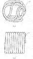
- the secondary form of the embolic coil 107 is in an " ⁇ " basket-like shape or a helical shape.
- embolic coils 107 of other shapes may be provided to adapt to aneurysms of different sizes.
- the present invention further provides a preparation method of an embolic coil conveying device, including:
- the stretch-resistant thread is fixed onto any one of the second to sixth rings of the embolic coil.
- the method further includes: coating a section where the stretch-resistant thread and the conductive wire are connected with a polymer adhesive to enhance the connection strength.
- the embolic coil can be wound with platinum alloy wires, and the platinum alloy coils can have various lengths and diameters.
- a platinum alloy wire can be wound around a mandrel to form a primary coil, and then the wound primary coil can further be wound on a mold according to a preset shape and subject to a shaping process, for example, to obtain a structure with the secondary form of an " ⁇ " basket-like shape or a helical shape.
- the platinum alloy coil is made of a wire with a diameter of 0.0762mm (0.003 inch), and is wound on a metal mandrel to form compact primary coils. These primary coils are used as the embolic coil 107.
- the wound primary coil is wound according to a preset secondary form of an " ⁇ " basket-like shape and subject to a shaping process, that is, the obtained secondary form of the embolic coil 107 is in an " ⁇ " basket-like shape.
- the distal end of the conductive wire 104 is made into a "U" shape (as shown in FIG. 3 ).
- the stretch-resistant thread 108 is axially extended inside the embolic coil 107 along the primary coil (as shown in a partial cross-sectional view in FIG. 2 ), and the stretch-resistant thread 108 is in cross connection with the "U"-shaped distal end of the conductive wire 104 to form a U-shaped proximal end (as shown in FIG. 3 ).
- One side of the "U"-shape of the proximal end of the stretch-resistant thread 108 is fixedly wound around any one of the second to sixth rings of the proximal end of the embolic coil 107 (as shown in FIG.
- An insulating layer 1042 is disposed on the conductive wire 104, and a detachment point 1041 (as shown in FIG. 3 ) that is not covered by the insulating layer is provided on the distal end of the conductive wire 104.
- a detachment section 103 is formed in a section where the conductive wire 104 and the stretch-resistant thread 108 are in cross connection. The length of the detachment section 103 is 0.5 mm. According to the three-point bending method shown in FIG. 10 , the bending modulus of elasticity of the detachment section 103 is 150 MPa.
- the three-point bending method shown in FIG. 10 includes: clamping the metal spring tube 102 and the embolic coil 107 respectively by a fixing device 200 after the conductive wire 104 and the stretch-resistant thread 108 are in cross connection to form the detachment section 103, and then applying a certain force to the detachment section 103, for example, pressing down by 10 mm, so as to calculate the bending modulus of elasticity.
- the embolic coil 107 has a helical structure (as shown in FIG. 9 ).
- the platinum alloy coil is made of a wire with a diameter of 0.03175 mm (0.00125 inch), and is similarly wound on the metal mandrel to form compact primary coils.
- the wound primary coils are subject to a shaping process according to a preset "helical" shape.
- the distal end of the conductive wire 104 is made into a "J" shape (as shown in FIG. 4 ).
- the stretch-resistant thread 108 is axially extended along the primary coil, and the stretch-resistant thread 108 is in cross connection with the "J"-shaped distal end of the conductive wire 104 to form a U-shaped proximal end (as shown in FIG. 4 ).
- One side of the "U"-shape of the proximal end of the stretch-resistant thread 108 is fixedly wound around any one of the second to the sixth rings at the proximal end of the embolic coil 107 (as shown in FIG. 2 ), the other side returns to the distal end of the embolic coil 107.
- An insulating layer is disposed on the conductive wire, and a detachment point that is not covered by the insulating layer is provided on the distal end of the conductive wire.
- a detachment section 103 is formed in a section where the conductive wire 104 and the stretch-resistant thread 108 are in cross connection.
- the length of the detachment section 103 is 1.0 mm. According to the three-point bending method shown in FIG. 10 , the bending modulus of elasticity of the detachment section 103 is 210 MPa.
- the embolic coil 107 has a helical structure (as shown in FIG. 9 ).
- the platinum alloy coil is made of a wire with a diameter of 0.0508 mm (0.002 inch), and is similarly wound on the metal mandrel to form compact primary coils.
- the wound primary coils are subject to a shaping process according to a preset "helical" shape.
- the distal end of the conductive wire 104 is made into a "J" shape (as shown in FIG. 5 ).
- the stretch-resistant thread 108 is axially extended along the primary coil, and the stretch-resistant thread 108 is in cross connection with the "J"-shaped distal end of the conductive wire 104 to form a J-shaped proximal end (as shown in FIG. 5 ).
- One side of the "J"-shaped proximal end of the stretch-resistant thread 108 is fixedly wound around the third ring at the proximal end of the embolic coil 107.
- An insulating layer is disposed on the conductive wire, and a detachment point that is not covered by the insulating layer is provided on the distal end of the conductive wire.
- a detachment section 103 is formed in a section where the conductive wire 104 and the stretch-resistant thread 108 are in cross connection.
- the length of the detachment section 103 is 0.5 mm.
- the bending modulus of elasticity of the detachment section 103 is 150 MPa.
- the distal end of the conductive wire 104 is designed to a "T" shape (as shown in FIGs. 6 and 7 ).
- the stretch-resistant thread 108 is axially extended along the primary coil, and the proximal end of the stretch-resistant thread 108 is designed to a "J" shape (as shown in FIG. 6 ) or a "U" shape (as shown in FIG. 7 ).
- An insulating layer is disposed on the conductive wire, and a detachment point that is not covered by the insulating layer is provided on the distal end of the conductive wire, and the conductive wire 104 and the stretch-resistant thread 108 are in cross connection.
- a section where the stretch-resistant thread 108 and the conductive wire 104 are in cross connection is coated with a polymer adhesive to enhance the connection strength.
- the embolic coil conveying device includes a pusher and an embolic coil.
- a distal end of the pusher and a proximal end of the embolic coil are connected to serve as a detachment section.
- a stretch-resistant thread is disposed in the embolic coil. The stretch-resistant thread is fixed at the proximal end of the embolic coil.
- a conductive wire is disposed in the pusher.
- An insulating layer is disposed on the conductive wire, and a detachment point that is not covered by the insulating layer is provided at the distal end of the conductive wire.
- the stretch-resistant thread is connected to the conductive wire.
- the present invention fixes the stretch-resistant thread at the proximal end of the embolic coil, so that the stretch-resistant thread is connected to the conductive wire, which reduces the length of the detachment section and makes the detachment section more flexible, thereby basically avoiding the kick-out of a microcatheter due to release of the embolic coil, and improving the success rate of the operation.
Landscapes
- Health & Medical Sciences (AREA)
- Life Sciences & Earth Sciences (AREA)
- Surgery (AREA)
- General Health & Medical Sciences (AREA)
- Animal Behavior & Ethology (AREA)
- Veterinary Medicine (AREA)
- Engineering & Computer Science (AREA)
- Biomedical Technology (AREA)
- Heart & Thoracic Surgery (AREA)
- Public Health (AREA)
- Medical Informatics (AREA)
- Molecular Biology (AREA)
- Reproductive Health (AREA)
- Nuclear Medicine, Radiotherapy & Molecular Imaging (AREA)
- Vascular Medicine (AREA)
- Neurosurgery (AREA)
- Pulmonology (AREA)
- Biophysics (AREA)
- Anesthesiology (AREA)
- Hematology (AREA)
- Surgical Instruments (AREA)
- Electrotherapy Devices (AREA)
- Manufacture Of Motors, Generators (AREA)
- Discharge Heating (AREA)
Claims (13)
- Emboliespulen-Fördervorrichtung, umfassend einen Schieber (106) und eine Emboliespule (107), wobei ein Abschnitt, in dem ein distales Ende des Schiebers (106) und ein proximales Ende (1071) der Emboliespule (107) verbunden sind, ein Trennabschnitt (103) ist;
wobei die Emboliespulen-Fördervorrichtung ferner umfasst: einen dehnungsresistenten Faden (108), der in der Emboliespule (107) angeordnet ist, wobei der dehnungsresistente Faden (108) an einem Ring an dem proximalen Ende (1071) der Emboliespule (107) befestigt ist; und einen leitfähigen Draht (104), der ausgebildet ist, durch ein Inneres des Schiebers (106) hindurchzuführen, wobei der leitfähige Draht (104) von einer Isolierschicht bedeckt ist, und wobei ein Trennpunkt, der nicht von der Isolierschicht bedeckt ist, an einem distalen Ende des leitfähigen Drahts (104) vorgesehen ist, dadurch gekennzeichnet, dass:
das distale Ende des leitfähigen Drahts (104) und ein proximales Ende des dehnungsresistenten Fadens (108) direkt kreuzverbunden sind. - Emboliespulen-Fördervorrichtung nach Anspruch 1, wobei der dehnungsresistente Faden (108) an einem der zweiten bis sechsten Ringe an dem proximalen Ende (1071) der Emboliespule (107) befestigt ist.
- Emboliespulen-Fördervorrichtung nach Anspruch 1, wobei der Trennabschnitt (103) einen Biege-Elastizitätsmodul von 150-220 MPa aufweist.
- Emboliespulen-Fördervorrichtung nach Anspruch 1, wobei der Trennabschnitt (103) eine Länge von 0,3 mm-1,0 mm aufweist.
- Emboliespulen-Fördervorrichtung nach Anspruch 1, wobei das distale Ende des leitfähigen Drahts (104) "J"-förmig, "U"-förmig oder "T"-förmig ist; wobei das proximale Ende des dehnungsresistenten Fadens (108) "J"-förmig oder "U"-förmig ist; und wobei der leitfähige Draht (104) und der dehnungsresistente Faden (108) in UU-förmiger Kreuzverbindung, UJ-förmiger Kreuzverbindung, JU-förmiger Kreuzverbindung, JJ-förmiger Kreuzverbindung, TU-förmiger Kreuzverbindung oder TJ-förmiger Kreuzverbindung sind.
- Emboliespulen-Fördervorrichtung nach Anspruch 1, wobei ein Abschnitt, in dem der leitfähige Draht (104) und der dehnungsresistente Faden (108) in Kreuzverbindung sind, mit einem Polymerklebstoff beschichtet ist.
- Emboliespulen-Fördervorrichtung nach Anspruch 1, wobei ein Material der Isolierschicht mindestens eines aus Polytetrafluorethylen, Polyethylenterephthalat, Polyetheramid und Polyimid umfasst.
- Emboliespulen-Fördervorrichtung nach Anspruch 1, ferner umfassend eine Trennvorrichtung (105), wobei ein proximales Ende des Schiebers (106) in die Trennvorrichtung (105) eingeführt ist, und wobei die Trennvorrichtung (105) ausgebildet ist, einen Gleichstrom von 0,5-5,0 mA an den leitfähigen Draht (104) anzulegen.
- Emboliespulen-Fördervorrichtung nach Anspruch 1, wobei die Emboliespule (107) eine korbähnliche "Ω"-Form oder eine Schraubenform aufweist.
- Herstellungsverfahren für die Emboliespulen-Fördervorrichtung nach Anspruch 1, umfassend:Bereitstellen eines Schiebers (106) und einer Emboliespule (107);Anordnen eines dehnungsresistenten Fadens (108) in der Emboliespule (107) und Befestigen des dehnungsresistenten Fadens (108) an einem proximalen Ende (1071) der Emboliespule (107);Hindurchführen eines leitfähigen Drahts (104) durch ein Inneres des Schiebers (106), Bedecken des leitfähigen Drahts (104) durch eine Isolierschicht und Bereitstellen eines Trennpunkts, der nicht durch die Isolierschicht bedeckt ist, an einem distalen Ende des leitfähigen Drahts (104); undKreuzverbinden eines proximalen Endes des dehnungsresistenten Fadens (108) mit dem distalen Ende des leitfähigen Drahts (104).
- Herstellungsverfahren für die Emboliespulen-Fördervorrichtung nach Anspruch 10, wobei der dehnungsresistente Faden (108) an einem der zweiten bis sechsten Ringe an dem proximalen Ende (1071) der Emboliespule (107) befestigt ist.
- Herstellungsverfahren für die Emboliespulen-Fördervorrichtung nach Anspruch 10, wobei das distale Ende des leitfähigen Drahts (104) "J"-förmig, "U"-förmig oder "T"-förmig ist; wobei das proximale Ende des dehnungsresistenten Fadens (108) "J"-förmig oder "U"-förmig ist; und wobei der leitfähige Draht (104) und der dehnungsresistente Faden (108) in UU-förmiger Kreuzverbindung, UJ-förmiger Kreuzverbindung, JU-förmiger Kreuzverbindung, JJ-förmiger Kreuzverbindung, TU-förmiger Kreuzverbindung oder TJ-förmiger Kreuzverbindung sind.
- Herstellungsverfahren für die Emboliespulen-Fördervorrichtung nach Anspruch 10, ferner umfassend ein Beschichten der Kreuzverbindung mit einem Polymerklebstoff.
Applications Claiming Priority (2)
| Application Number | Priority Date | Filing Date | Title |
|---|---|---|---|
| CN201710703690.0A CN107374690A (zh) | 2017-08-16 | 2017-08-16 | 栓塞线圈输送装置及其制备方法 |
| PCT/CN2018/099541 WO2019033978A1 (zh) | 2017-08-16 | 2018-08-09 | 栓塞线圈输送装置及其制备方法 |
Publications (3)
| Publication Number | Publication Date |
|---|---|
| EP3669799A1 EP3669799A1 (de) | 2020-06-24 |
| EP3669799A4 EP3669799A4 (de) | 2020-08-05 |
| EP3669799B1 true EP3669799B1 (de) | 2022-11-23 |
Family
ID=60352929
Family Applications (1)
| Application Number | Title | Priority Date | Filing Date |
|---|---|---|---|
| EP18847082.7A Active EP3669799B1 (de) | 2017-08-16 | 2018-08-09 | Embolie-spulen-fördervorrichtung und herstellungsverfahren dafür |
Country Status (9)
| Country | Link |
|---|---|
| US (1) | US11172934B2 (de) |
| EP (1) | EP3669799B1 (de) |
| JP (1) | JP7026779B2 (de) |
| KR (1) | KR102365255B1 (de) |
| CN (1) | CN107374690A (de) |
| BR (1) | BR112020003021A2 (de) |
| ES (1) | ES2937238T3 (de) |
| PH (1) | PH12020500348A1 (de) |
| WO (1) | WO2019033978A1 (de) |
Families Citing this family (15)
| Publication number | Priority date | Publication date | Assignee | Title |
|---|---|---|---|---|
| US10925611B2 (en) | 2015-01-20 | 2021-02-23 | Neurogami Medical, Inc. | Packaging for surgical implant |
| US11484319B2 (en) | 2015-01-20 | 2022-11-01 | Neurogami Medical, Inc. | Delivery system for micrograft for treating intracranial aneurysms |
| US10857012B2 (en) | 2015-01-20 | 2020-12-08 | Neurogami Medical, Inc. | Vascular implant |
| JP6763864B2 (ja) | 2015-01-20 | 2020-09-30 | ニューロガミ メディカル インコーポレイテッド | 頭蓋内動脈瘤の治療のためのマイクログラフトおよび使用方法 |
| US10736730B2 (en) | 2015-01-20 | 2020-08-11 | Neurogami Medical, Inc. | Vascular implant |
| CN107374690A (zh) | 2017-08-16 | 2017-11-24 | 微创神通医疗科技(上海)有限公司 | 栓塞线圈输送装置及其制备方法 |
| EP3755238B1 (de) * | 2018-02-23 | 2023-12-27 | Boston Scientific Scimed, Inc. | Abgabevorrichtung zur verwendung mit einem embolischen material |
| CN108420486A (zh) * | 2018-03-30 | 2018-08-21 | 北京泰杰伟业科技有限公司 | 一种用于栓塞弹簧圈的输送装置 |
| CN115363664B (zh) * | 2020-12-29 | 2024-11-26 | 聚辉医疗科技(深圳)有限公司 | 栓塞弹簧圈系统 |
| CN115363663B (zh) * | 2020-12-29 | 2024-11-22 | 聚辉医疗科技(深圳)有限公司 | 栓塞弹簧圈系统 |
| CN112656476B (zh) * | 2020-12-31 | 2025-12-30 | 神遁医疗科技(上海)有限公司 | 一种栓塞物及其制备方法 |
| CN112641484B (zh) * | 2020-12-31 | 2025-04-15 | 神遁医疗科技(上海)有限公司 | 一种栓塞物及其制备方法 |
| CN113491557A (zh) * | 2021-09-08 | 2021-10-12 | 微创神通医疗科技(上海)有限公司 | 栓塞装置以及栓塞系统 |
| CN114041845A (zh) * | 2021-12-10 | 2022-02-15 | 上海拓舜医疗科技有限公司 | 一种介入栓塞用弹簧圈的输送系统 |
| CN115137432B (zh) * | 2022-04-25 | 2024-10-01 | 深圳佰特微医疗科技有限公司 | 栓塞系统 |
Citations (1)
| Publication number | Priority date | Publication date | Assignee | Title |
|---|---|---|---|---|
| US7608089B2 (en) * | 2004-12-22 | 2009-10-27 | Boston Scientific Scimed, Inc. | Vaso-occlusive device having pivotable coupling |
Family Cites Families (11)
| Publication number | Priority date | Publication date | Assignee | Title |
|---|---|---|---|---|
| US5984929A (en) * | 1997-08-29 | 1999-11-16 | Target Therapeutics, Inc. | Fast detaching electronically isolated implant |
| US20060271097A1 (en) * | 2005-05-31 | 2006-11-30 | Kamal Ramzipoor | Electrolytically detachable implantable devices |
| US9636115B2 (en) * | 2005-06-14 | 2017-05-02 | Stryker Corporation | Vaso-occlusive delivery device with kink resistant, flexible distal end |
| AU2008359873B8 (en) * | 2007-07-27 | 2015-09-10 | Microvention, Inc. | Detachable coil incorporating stretch resistance |
| AU2009303677B2 (en) * | 2008-10-13 | 2014-04-24 | Stryker European Holdings I, Llc | Vaso-occlusive coil delivery system |
| EP2668914A1 (de) * | 2012-06-01 | 2013-12-04 | Acandis GmbH & Co. KG | Implantatsystem |
| US9566072B2 (en) * | 2013-12-27 | 2017-02-14 | Blockade Medical, LLC | Coil system |
| CN108697425A (zh) * | 2015-12-18 | 2018-10-23 | 巴尔特美国 | 具有可弯曲的分离区的血管植入系统和过程 |
| CN206356503U (zh) * | 2016-11-29 | 2017-07-28 | 微创神通医疗科技(上海)有限公司 | 弹簧圈 |
| CN208725798U (zh) * | 2017-08-16 | 2019-04-12 | 微创神通医疗科技(上海)有限公司 | 栓塞线圈输送装置 |
| CN107374690A (zh) | 2017-08-16 | 2017-11-24 | 微创神通医疗科技(上海)有限公司 | 栓塞线圈输送装置及其制备方法 |
-
2017
- 2017-08-16 CN CN201710703690.0A patent/CN107374690A/zh active Pending
-
2018
- 2018-08-09 US US16/639,456 patent/US11172934B2/en active Active
- 2018-08-09 JP JP2020509114A patent/JP7026779B2/ja active Active
- 2018-08-09 ES ES18847082T patent/ES2937238T3/es active Active
- 2018-08-09 KR KR1020207007381A patent/KR102365255B1/ko not_active Expired - Fee Related
- 2018-08-09 EP EP18847082.7A patent/EP3669799B1/de active Active
- 2018-08-09 WO PCT/CN2018/099541 patent/WO2019033978A1/zh not_active Ceased
- 2018-08-09 BR BR112020003021-0A patent/BR112020003021A2/pt not_active Application Discontinuation
-
2020
- 2020-02-17 PH PH12020500348A patent/PH12020500348A1/en unknown
Patent Citations (1)
| Publication number | Priority date | Publication date | Assignee | Title |
|---|---|---|---|---|
| US7608089B2 (en) * | 2004-12-22 | 2009-10-27 | Boston Scientific Scimed, Inc. | Vaso-occlusive device having pivotable coupling |
Also Published As
| Publication number | Publication date |
|---|---|
| CN107374690A (zh) | 2017-11-24 |
| EP3669799A1 (de) | 2020-06-24 |
| EP3669799A4 (de) | 2020-08-05 |
| US11172934B2 (en) | 2021-11-16 |
| WO2019033978A1 (zh) | 2019-02-21 |
| PH12020500348A1 (en) | 2021-01-25 |
| ES2937238T3 (es) | 2023-03-27 |
| JP2020530802A (ja) | 2020-10-29 |
| KR20200044843A (ko) | 2020-04-29 |
| JP7026779B2 (ja) | 2022-02-28 |
| BR112020003021A2 (pt) | 2020-07-28 |
| KR102365255B1 (ko) | 2022-02-23 |
| US20200281598A1 (en) | 2020-09-10 |
Similar Documents
| Publication | Publication Date | Title |
|---|---|---|
| US11172934B2 (en) | Embolism coil conveying device and preparation method therefor | |
| US9504475B2 (en) | Delivery wire for occlusive device delivery system | |
| US9636115B2 (en) | Vaso-occlusive delivery device with kink resistant, flexible distal end | |
| US20120209310A1 (en) | Vaso-occlusive device delivery system | |
| US9486223B2 (en) | Mechanically datachable vaso-occlusive device | |
| AU2009303677B2 (en) | Vaso-occlusive coil delivery system | |
| US8992563B2 (en) | Delivery wire assembly for occlusive device delivery system | |
| US20110118776A1 (en) | Delivery wire assembly for occlusive device delivery system | |
| US9855050B2 (en) | Vasculature occlusion device detachment system with tapered corewire and single loop fuse detachment | |
| US20100234872A1 (en) | Electrical contact for occlusive device delivery system | |
| US20100268251A1 (en) | Delivery wire for occlusive device delivery system and method of manufacture | |
| WO2019026364A1 (ja) | 生体内留置具、生体内留置具送達システムおよび生体内留置具の製造方法 |
Legal Events
| Date | Code | Title | Description |
|---|---|---|---|
| STAA | Information on the status of an ep patent application or granted ep patent |
Free format text: STATUS: THE INTERNATIONAL PUBLICATION HAS BEEN MADE |
|
| PUAI | Public reference made under article 153(3) epc to a published international application that has entered the european phase |
Free format text: ORIGINAL CODE: 0009012 |
|
| STAA | Information on the status of an ep patent application or granted ep patent |
Free format text: STATUS: REQUEST FOR EXAMINATION WAS MADE |
|
| 17P | Request for examination filed |
Effective date: 20200309 |
|
| AK | Designated contracting states |
Kind code of ref document: A1 Designated state(s): AL AT BE BG CH CY CZ DE DK EE ES FI FR GB GR HR HU IE IS IT LI LT LU LV MC MK MT NL NO PL PT RO RS SE SI SK SM TR |
|
| AX | Request for extension of the european patent |
Extension state: BA ME |
|
| A4 | Supplementary search report drawn up and despatched |
Effective date: 20200706 |
|
| RIC1 | Information provided on ipc code assigned before grant |
Ipc: A61B 17/12 20060101AFI20200630BHEP |
|
| DAV | Request for validation of the european patent (deleted) | ||
| DAX | Request for extension of the european patent (deleted) | ||
| GRAP | Despatch of communication of intention to grant a patent |
Free format text: ORIGINAL CODE: EPIDOSNIGR1 |
|
| STAA | Information on the status of an ep patent application or granted ep patent |
Free format text: STATUS: GRANT OF PATENT IS INTENDED |
|
| INTG | Intention to grant announced |
Effective date: 20220720 |
|
| GRAS | Grant fee paid |
Free format text: ORIGINAL CODE: EPIDOSNIGR3 |
|
| GRAA | (expected) grant |
Free format text: ORIGINAL CODE: 0009210 |
|
| STAA | Information on the status of an ep patent application or granted ep patent |
Free format text: STATUS: THE PATENT HAS BEEN GRANTED |
|
| AK | Designated contracting states |
Kind code of ref document: B1 Designated state(s): AL AT BE BG CH CY CZ DE DK EE ES FI FR GB GR HR HU IE IS IT LI LT LU LV MC MK MT NL NO PL PT RO RS SE SI SK SM TR |
|
| REG | Reference to a national code |
Ref country code: GB Ref legal event code: FG4D |
|
| REG | Reference to a national code |
Ref country code: CH Ref legal event code: EP |
|
| REG | Reference to a national code |
Ref country code: DE Ref legal event code: R096 Ref document number: 602018043469 Country of ref document: DE |
|
| REG | Reference to a national code |
Ref country code: AT Ref legal event code: REF Ref document number: 1532660 Country of ref document: AT Kind code of ref document: T Effective date: 20221215 |
|
| REG | Reference to a national code |
Ref country code: IE Ref legal event code: FG4D |
|
| REG | Reference to a national code |
Ref country code: LT Ref legal event code: MG9D |
|
| REG | Reference to a national code |
Ref country code: ES Ref legal event code: FG2A Ref document number: 2937238 Country of ref document: ES Kind code of ref document: T3 Effective date: 20230327 |
|
| REG | Reference to a national code |
Ref country code: NL Ref legal event code: MP Effective date: 20221123 |
|
| REG | Reference to a national code |
Ref country code: AT Ref legal event code: MK05 Ref document number: 1532660 Country of ref document: AT Kind code of ref document: T Effective date: 20221123 |
|
| PG25 | Lapsed in a contracting state [announced via postgrant information from national office to epo] |
Ref country code: SE Free format text: LAPSE BECAUSE OF FAILURE TO SUBMIT A TRANSLATION OF THE DESCRIPTION OR TO PAY THE FEE WITHIN THE PRESCRIBED TIME-LIMIT Effective date: 20221123 Ref country code: PT Free format text: LAPSE BECAUSE OF FAILURE TO SUBMIT A TRANSLATION OF THE DESCRIPTION OR TO PAY THE FEE WITHIN THE PRESCRIBED TIME-LIMIT Effective date: 20230323 Ref country code: NO Free format text: LAPSE BECAUSE OF FAILURE TO SUBMIT A TRANSLATION OF THE DESCRIPTION OR TO PAY THE FEE WITHIN THE PRESCRIBED TIME-LIMIT Effective date: 20230223 Ref country code: LT Free format text: LAPSE BECAUSE OF FAILURE TO SUBMIT A TRANSLATION OF THE DESCRIPTION OR TO PAY THE FEE WITHIN THE PRESCRIBED TIME-LIMIT Effective date: 20221123 Ref country code: FI Free format text: LAPSE BECAUSE OF FAILURE TO SUBMIT A TRANSLATION OF THE DESCRIPTION OR TO PAY THE FEE WITHIN THE PRESCRIBED TIME-LIMIT Effective date: 20221123 Ref country code: AT Free format text: LAPSE BECAUSE OF FAILURE TO SUBMIT A TRANSLATION OF THE DESCRIPTION OR TO PAY THE FEE WITHIN THE PRESCRIBED TIME-LIMIT Effective date: 20221123 |
|
| PG25 | Lapsed in a contracting state [announced via postgrant information from national office to epo] |
Ref country code: RS Free format text: LAPSE BECAUSE OF FAILURE TO SUBMIT A TRANSLATION OF THE DESCRIPTION OR TO PAY THE FEE WITHIN THE PRESCRIBED TIME-LIMIT Effective date: 20221123 Ref country code: PL Free format text: LAPSE BECAUSE OF FAILURE TO SUBMIT A TRANSLATION OF THE DESCRIPTION OR TO PAY THE FEE WITHIN THE PRESCRIBED TIME-LIMIT Effective date: 20221123 Ref country code: LV Free format text: LAPSE BECAUSE OF FAILURE TO SUBMIT A TRANSLATION OF THE DESCRIPTION OR TO PAY THE FEE WITHIN THE PRESCRIBED TIME-LIMIT Effective date: 20221123 Ref country code: IS Free format text: LAPSE BECAUSE OF FAILURE TO SUBMIT A TRANSLATION OF THE DESCRIPTION OR TO PAY THE FEE WITHIN THE PRESCRIBED TIME-LIMIT Effective date: 20230323 Ref country code: HR Free format text: LAPSE BECAUSE OF FAILURE TO SUBMIT A TRANSLATION OF THE DESCRIPTION OR TO PAY THE FEE WITHIN THE PRESCRIBED TIME-LIMIT Effective date: 20221123 Ref country code: GR Free format text: LAPSE BECAUSE OF FAILURE TO SUBMIT A TRANSLATION OF THE DESCRIPTION OR TO PAY THE FEE WITHIN THE PRESCRIBED TIME-LIMIT Effective date: 20230224 |
|
| P01 | Opt-out of the competence of the unified patent court (upc) registered |
Effective date: 20230515 |
|
| PG25 | Lapsed in a contracting state [announced via postgrant information from national office to epo] |
Ref country code: NL Free format text: LAPSE BECAUSE OF FAILURE TO SUBMIT A TRANSLATION OF THE DESCRIPTION OR TO PAY THE FEE WITHIN THE PRESCRIBED TIME-LIMIT Effective date: 20221123 |
|
| PG25 | Lapsed in a contracting state [announced via postgrant information from national office to epo] |
Ref country code: SM Free format text: LAPSE BECAUSE OF FAILURE TO SUBMIT A TRANSLATION OF THE DESCRIPTION OR TO PAY THE FEE WITHIN THE PRESCRIBED TIME-LIMIT Effective date: 20221123 Ref country code: RO Free format text: LAPSE BECAUSE OF FAILURE TO SUBMIT A TRANSLATION OF THE DESCRIPTION OR TO PAY THE FEE WITHIN THE PRESCRIBED TIME-LIMIT Effective date: 20221123 Ref country code: EE Free format text: LAPSE BECAUSE OF FAILURE TO SUBMIT A TRANSLATION OF THE DESCRIPTION OR TO PAY THE FEE WITHIN THE PRESCRIBED TIME-LIMIT Effective date: 20221123 Ref country code: DK Free format text: LAPSE BECAUSE OF FAILURE TO SUBMIT A TRANSLATION OF THE DESCRIPTION OR TO PAY THE FEE WITHIN THE PRESCRIBED TIME-LIMIT Effective date: 20221123 Ref country code: CZ Free format text: LAPSE BECAUSE OF FAILURE TO SUBMIT A TRANSLATION OF THE DESCRIPTION OR TO PAY THE FEE WITHIN THE PRESCRIBED TIME-LIMIT Effective date: 20221123 |
|
| REG | Reference to a national code |
Ref country code: DE Ref legal event code: R097 Ref document number: 602018043469 Country of ref document: DE |
|
| PG25 | Lapsed in a contracting state [announced via postgrant information from national office to epo] |
Ref country code: SK Free format text: LAPSE BECAUSE OF FAILURE TO SUBMIT A TRANSLATION OF THE DESCRIPTION OR TO PAY THE FEE WITHIN THE PRESCRIBED TIME-LIMIT Effective date: 20221123 Ref country code: AL Free format text: LAPSE BECAUSE OF FAILURE TO SUBMIT A TRANSLATION OF THE DESCRIPTION OR TO PAY THE FEE WITHIN THE PRESCRIBED TIME-LIMIT Effective date: 20221123 |
|
| PLBE | No opposition filed within time limit |
Free format text: ORIGINAL CODE: 0009261 |
|
| STAA | Information on the status of an ep patent application or granted ep patent |
Free format text: STATUS: NO OPPOSITION FILED WITHIN TIME LIMIT |
|
| PGFP | Annual fee paid to national office [announced via postgrant information from national office to epo] |
Ref country code: IT Payment date: 20230825 Year of fee payment: 6 Ref country code: IE Payment date: 20230822 Year of fee payment: 6 |
|
| 26N | No opposition filed |
Effective date: 20230824 |
|
| PG25 | Lapsed in a contracting state [announced via postgrant information from national office to epo] |
Ref country code: SI Free format text: LAPSE BECAUSE OF FAILURE TO SUBMIT A TRANSLATION OF THE DESCRIPTION OR TO PAY THE FEE WITHIN THE PRESCRIBED TIME-LIMIT Effective date: 20221123 |
|
| PGFP | Annual fee paid to national office [announced via postgrant information from national office to epo] |
Ref country code: ES Payment date: 20231027 Year of fee payment: 6 |
|
| PG25 | Lapsed in a contracting state [announced via postgrant information from national office to epo] |
Ref country code: MC Free format text: LAPSE BECAUSE OF FAILURE TO SUBMIT A TRANSLATION OF THE DESCRIPTION OR TO PAY THE FEE WITHIN THE PRESCRIBED TIME-LIMIT Effective date: 20221123 |
|
| REG | Reference to a national code |
Ref country code: CH Ref legal event code: PL |
|
| PG25 | Lapsed in a contracting state [announced via postgrant information from national office to epo] |
Ref country code: MC Free format text: LAPSE BECAUSE OF FAILURE TO SUBMIT A TRANSLATION OF THE DESCRIPTION OR TO PAY THE FEE WITHIN THE PRESCRIBED TIME-LIMIT Effective date: 20221123 |
|
| PG25 | Lapsed in a contracting state [announced via postgrant information from national office to epo] |
Ref country code: LU Free format text: LAPSE BECAUSE OF NON-PAYMENT OF DUE FEES Effective date: 20230809 |
|
| PG25 | Lapsed in a contracting state [announced via postgrant information from national office to epo] |
Ref country code: LU Free format text: LAPSE BECAUSE OF NON-PAYMENT OF DUE FEES Effective date: 20230809 Ref country code: CH Free format text: LAPSE BECAUSE OF NON-PAYMENT OF DUE FEES Effective date: 20230831 |
|
| REG | Reference to a national code |
Ref country code: BE Ref legal event code: MM Effective date: 20230831 |
|
| PG25 | Lapsed in a contracting state [announced via postgrant information from national office to epo] |
Ref country code: BE Free format text: LAPSE BECAUSE OF NON-PAYMENT OF DUE FEES Effective date: 20230831 |
|
| PG25 | Lapsed in a contracting state [announced via postgrant information from national office to epo] |
Ref country code: BG Free format text: LAPSE BECAUSE OF FAILURE TO SUBMIT A TRANSLATION OF THE DESCRIPTION OR TO PAY THE FEE WITHIN THE PRESCRIBED TIME-LIMIT Effective date: 20221123 |
|
| PG25 | Lapsed in a contracting state [announced via postgrant information from national office to epo] |
Ref country code: BG Free format text: LAPSE BECAUSE OF FAILURE TO SUBMIT A TRANSLATION OF THE DESCRIPTION OR TO PAY THE FEE WITHIN THE PRESCRIBED TIME-LIMIT Effective date: 20221123 |
|
| PG25 | Lapsed in a contracting state [announced via postgrant information from national office to epo] |
Ref country code: IT Free format text: LAPSE BECAUSE OF NON-PAYMENT OF DUE FEES Effective date: 20240809 |
|
| PG25 | Lapsed in a contracting state [announced via postgrant information from national office to epo] |
Ref country code: CY Free format text: LAPSE BECAUSE OF FAILURE TO SUBMIT A TRANSLATION OF THE DESCRIPTION OR TO PAY THE FEE WITHIN THE PRESCRIBED TIME-LIMIT; INVALID AB INITIO Effective date: 20180809 |
|
| PG25 | Lapsed in a contracting state [announced via postgrant information from national office to epo] |
Ref country code: IE Free format text: LAPSE BECAUSE OF NON-PAYMENT OF DUE FEES Effective date: 20240809 |
|
| PG25 | Lapsed in a contracting state [announced via postgrant information from national office to epo] |
Ref country code: HU Free format text: LAPSE BECAUSE OF FAILURE TO SUBMIT A TRANSLATION OF THE DESCRIPTION OR TO PAY THE FEE WITHIN THE PRESCRIBED TIME-LIMIT; INVALID AB INITIO Effective date: 20180809 |
|
| REG | Reference to a national code |
Ref country code: ES Ref legal event code: FD2A Effective date: 20250926 |
|
| PG25 | Lapsed in a contracting state [announced via postgrant information from national office to epo] |
Ref country code: ES Free format text: LAPSE BECAUSE OF NON-PAYMENT OF DUE FEES Effective date: 20240810 |
|
| PGFP | Annual fee paid to national office [announced via postgrant information from national office to epo] |
Ref country code: DE Payment date: 20250820 Year of fee payment: 8 |
|
| PGFP | Annual fee paid to national office [announced via postgrant information from national office to epo] |
Ref country code: GB Payment date: 20250820 Year of fee payment: 8 |
|
| PGFP | Annual fee paid to national office [announced via postgrant information from national office to epo] |
Ref country code: FR Payment date: 20250828 Year of fee payment: 8 |
|
| PG25 | Lapsed in a contracting state [announced via postgrant information from national office to epo] |
Ref country code: TR Free format text: LAPSE BECAUSE OF FAILURE TO SUBMIT A TRANSLATION OF THE DESCRIPTION OR TO PAY THE FEE WITHIN THE PRESCRIBED TIME-LIMIT Effective date: 20221123 |