EP3669064B1 - Vaned valve for exhaust gas recirculation line - Google Patents
Vaned valve for exhaust gas recirculation line Download PDFInfo
- Publication number
- EP3669064B1 EP3669064B1 EP17921891.2A EP17921891A EP3669064B1 EP 3669064 B1 EP3669064 B1 EP 3669064B1 EP 17921891 A EP17921891 A EP 17921891A EP 3669064 B1 EP3669064 B1 EP 3669064B1
- Authority
- EP
- European Patent Office
- Prior art keywords
- valve
- barrel
- vanes
- interior surface
- set forth
- Prior art date
- Legal status (The legal status is an assumption and is not a legal conclusion. Google has not performed a legal analysis and makes no representation as to the accuracy of the status listed.)
- Active
Links
Images



Classifications
-
- F—MECHANICAL ENGINEERING; LIGHTING; HEATING; WEAPONS; BLASTING
- F02—COMBUSTION ENGINES; HOT-GAS OR COMBUSTION-PRODUCT ENGINE PLANTS
- F02M—SUPPLYING COMBUSTION ENGINES IN GENERAL WITH COMBUSTIBLE MIXTURES OR CONSTITUENTS THEREOF
- F02M26/00—Engine-pertinent apparatus for adding exhaust gases to combustion-air, main fuel or fuel-air mixture, e.g. by exhaust gas recirculation [EGR] systems
- F02M26/65—Constructional details of EGR valves
- F02M26/71—Multi-way valves
-
- F—MECHANICAL ENGINEERING; LIGHTING; HEATING; WEAPONS; BLASTING
- F02—COMBUSTION ENGINES; HOT-GAS OR COMBUSTION-PRODUCT ENGINE PLANTS
- F02M—SUPPLYING COMBUSTION ENGINES IN GENERAL WITH COMBUSTIBLE MIXTURES OR CONSTITUENTS THEREOF
- F02M26/00—Engine-pertinent apparatus for adding exhaust gases to combustion-air, main fuel or fuel-air mixture, e.g. by exhaust gas recirculation [EGR] systems
- F02M26/65—Constructional details of EGR valves
- F02M26/66—Lift valves, e.g. poppet valves
-
- F—MECHANICAL ENGINEERING; LIGHTING; HEATING; WEAPONS; BLASTING
- F02—COMBUSTION ENGINES; HOT-GAS OR COMBUSTION-PRODUCT ENGINE PLANTS
- F02M—SUPPLYING COMBUSTION ENGINES IN GENERAL WITH COMBUSTIBLE MIXTURES OR CONSTITUENTS THEREOF
- F02M26/00—Engine-pertinent apparatus for adding exhaust gases to combustion-air, main fuel or fuel-air mixture, e.g. by exhaust gas recirculation [EGR] systems
- F02M26/65—Constructional details of EGR valves
- F02M26/66—Lift valves, e.g. poppet valves
- F02M26/68—Closing members; Valve seats; Flow passages
-
- F—MECHANICAL ENGINEERING; LIGHTING; HEATING; WEAPONS; BLASTING
- F02—COMBUSTION ENGINES; HOT-GAS OR COMBUSTION-PRODUCT ENGINE PLANTS
- F02M—SUPPLYING COMBUSTION ENGINES IN GENERAL WITH COMBUSTIBLE MIXTURES OR CONSTITUENTS THEREOF
- F02M26/00—Engine-pertinent apparatus for adding exhaust gases to combustion-air, main fuel or fuel-air mixture, e.g. by exhaust gas recirculation [EGR] systems
- F02M26/65—Constructional details of EGR valves
- F02M26/66—Lift valves, e.g. poppet valves
- F02M26/69—Lift valves, e.g. poppet valves having two or more valve-closing members
-
- F—MECHANICAL ENGINEERING; LIGHTING; HEATING; WEAPONS; BLASTING
- F16—ENGINEERING ELEMENTS AND UNITS; GENERAL MEASURES FOR PRODUCING AND MAINTAINING EFFECTIVE FUNCTIONING OF MACHINES OR INSTALLATIONS; THERMAL INSULATION IN GENERAL
- F16K—VALVES; TAPS; COCKS; ACTUATING-FLOATS; DEVICES FOR VENTING OR AERATING
- F16K11/00—Multiple-way valves, e.g. mixing valves; Pipe fittings incorporating such valves
- F16K11/10—Multiple-way valves, e.g. mixing valves; Pipe fittings incorporating such valves with two or more closure members not moving as a unit
- F16K11/14—Multiple-way valves, e.g. mixing valves; Pipe fittings incorporating such valves with two or more closure members not moving as a unit operated by one actuating member, e.g. a handle
- F16K11/16—Multiple-way valves, e.g. mixing valves; Pipe fittings incorporating such valves with two or more closure members not moving as a unit operated by one actuating member, e.g. a handle which only slides, or only turns, or only swings in one plane
- F16K11/161—Multiple-way valves, e.g. mixing valves; Pipe fittings incorporating such valves with two or more closure members not moving as a unit operated by one actuating member, e.g. a handle which only slides, or only turns, or only swings in one plane only slides
-
- F—MECHANICAL ENGINEERING; LIGHTING; HEATING; WEAPONS; BLASTING
- F16—ENGINEERING ELEMENTS AND UNITS; GENERAL MEASURES FOR PRODUCING AND MAINTAINING EFFECTIVE FUNCTIONING OF MACHINES OR INSTALLATIONS; THERMAL INSULATION IN GENERAL
- F16K—VALVES; TAPS; COCKS; ACTUATING-FLOATS; DEVICES FOR VENTING OR AERATING
- F16K47/00—Means in valves for absorbing fluid energy
- F16K47/08—Means in valves for absorbing fluid energy for decreasing pressure or noise level and having a throttling member separate from the closure member, e.g. screens, slots, labyrinths
-
- F—MECHANICAL ENGINEERING; LIGHTING; HEATING; WEAPONS; BLASTING
- F02—COMBUSTION ENGINES; HOT-GAS OR COMBUSTION-PRODUCT ENGINE PLANTS
- F02M—SUPPLYING COMBUSTION ENGINES IN GENERAL WITH COMBUSTIBLE MIXTURES OR CONSTITUENTS THEREOF
- F02M26/00—Engine-pertinent apparatus for adding exhaust gases to combustion-air, main fuel or fuel-air mixture, e.g. by exhaust gas recirculation [EGR] systems
- F02M26/13—Arrangement or layout of EGR passages, e.g. in relation to specific engine parts or for incorporation of accessories
- F02M26/14—Arrangement or layout of EGR passages, e.g. in relation to specific engine parts or for incorporation of accessories in relation to the exhaust system
- F02M26/16—Arrangement or layout of EGR passages, e.g. in relation to specific engine parts or for incorporation of accessories in relation to the exhaust system with EGR valves located at or near the connection to the exhaust system
-
- F—MECHANICAL ENGINEERING; LIGHTING; HEATING; WEAPONS; BLASTING
- F02—COMBUSTION ENGINES; HOT-GAS OR COMBUSTION-PRODUCT ENGINE PLANTS
- F02M—SUPPLYING COMBUSTION ENGINES IN GENERAL WITH COMBUSTIBLE MIXTURES OR CONSTITUENTS THEREOF
- F02M26/00—Engine-pertinent apparatus for adding exhaust gases to combustion-air, main fuel or fuel-air mixture, e.g. by exhaust gas recirculation [EGR] systems
- F02M26/13—Arrangement or layout of EGR passages, e.g. in relation to specific engine parts or for incorporation of accessories
- F02M26/17—Arrangement or layout of EGR passages, e.g. in relation to specific engine parts or for incorporation of accessories in relation to the intake system
- F02M26/21—Arrangement or layout of EGR passages, e.g. in relation to specific engine parts or for incorporation of accessories in relation to the intake system with EGR valves located at or near the connection to the intake system
-
- F—MECHANICAL ENGINEERING; LIGHTING; HEATING; WEAPONS; BLASTING
- F02—COMBUSTION ENGINES; HOT-GAS OR COMBUSTION-PRODUCT ENGINE PLANTS
- F02M—SUPPLYING COMBUSTION ENGINES IN GENERAL WITH COMBUSTIBLE MIXTURES OR CONSTITUENTS THEREOF
- F02M26/00—Engine-pertinent apparatus for adding exhaust gases to combustion-air, main fuel or fuel-air mixture, e.g. by exhaust gas recirculation [EGR] systems
- F02M26/52—Systems for actuating EGR valves
- F02M26/53—Systems for actuating EGR valves using electric actuators, e.g. solenoids
Definitions
- the present envention relates generally to valves and, more particularly, tovalves for exhaust gas reciruclation lines in engines.
- EGR exhaust gas recirculation
- diesel engines the EGR volumetric flow rate (or equivalently the EGR mass flow rate) is largely dependent on the aerodynamic design of the valve. It is known in such EGR systems to use poppet/barrel style valves that tend to exhibit significant total pressure loss due to poor aerodynamic designs which produce complicated fluid dynamics effects.
- a front barrel is connected to an exhaust line for a front group of cylinders of the engine, and a rear barrel is connected to an exhaust line for a rear group of cylinders.
- a center barrel is provided between the front and rear barrels and an outlet opening of the center barrel is connected to the intake line of the engine.
- a poppet valve is provided for simultaneously opening and closing openings between the front barrel and the center barrel and between the rear barrel and the center barrel.
- Two valve heads are mounted on a common valve stem and are sented in respective valve seats in the openings between the front barrel and the center barrel and between the rear barrel and the center barrel.
- the stagnation zone is a major cause of loss of total pressure in this valve.
- the EGR flow that enters the center barrel front the rear cylinder must flow around the valve head in the center barrel and a portion of the fluid flow is directed upwardly towarda top of the center barrel and impinges the to ⁇ p wall of the center barrel (in a direction that shall be referred to as vertical) where it decelerates to a stagnation point.
- the flow that impinges the top wall is also deflected by the top wall from its original direction to flow radially around the center barrel in what shall be referred to as a radial wall flow.
- the radial wall flow accelerates from the stagnation point until some degree of static pressure recovery has occurred throughout a layer of flow along the wall or periphery of the center barrel.
- Radial wall flows are formed in opposing directions at the top wall of the center barrel and collide with each other as they flow along the walls of the center barrel away from the top of the center barrel and form deflection regions resulting in the further recirculation of the working fluid flow. It is similar to a typical bend pipe flow and rapidly varied flow can often be observed in different regions of the valve that could extend downstream toward the outlet of the center barrel where strong transverse variations in the velocity distribution and induced turbulent flow are evident as the EGR flow comes around the impingement regions.
- a valve for an exhaust gas recirculation line in an engine comprises a first barrel having an ninlet end for receiving exhaust from a first group of one or more cylinders, a second barrel having an inlet end for receiving exhaust from a second group of one or more cylinders, a center barrel disposed between the first barrel and the second barrel and having an outlet opening for directing exhaust gas toward an intake of the engine, the first barrel and the center barrel being adapted to bein fluid communication through a first inlet opening, and the second barrel and the center barrel being adapted to be in fluid communication through a second inlet opening, and a poppet valve comprising a stem and a first valve head and a second valve head mounted on the stem, a first valve seat against which the first valve head is arranged to be seated in the first barrel around the first inlet opening, and a second valve seat against which the second valve head is arranged to be seated in the center d the poppet valve being movable between a closed position in which the first valve head
- a valve comprises a valve barrel having an outlet opening for directing fluid out of the valve barrel, a first inlet opening in a first wall of the valve barrel and a second inlet opening in a second wall of the valve barrel, central axes of the first inlet opening and the second inlet opening being substantially perpendicular to a central axis of the outlet opening, and a poppet valve comprising a stem and a first valve head and a second valve head mounted on the stem, a first valve seat against which the first valve head is arranged to be seated outside the valve barrel around the first inlet opening, and a second valve seat against which the second valve head is arranged to be seated in the valve barrel around the second inlet opening, the poppet valve being movable between a closed position in which the first vavle head is seated against the first valve seat and the second valve head is seated against the second valve seat and an open position in which the first valve head is seated against the second valve seat
- a valve 21 for an exhaust gas recirculation line 23 in an engine 25 is provided as seen in FIG. 1
- the engine 25 comprises a first group 27 of one ormore cylinders connected to a first exhaust manifold 29 leading to a first exhaust line 31 and a second group 33 of one or more cylinders connected to a second exhaust manifold 35 leading to a second exhaust line 37.
- a configuration can be found, for example, in a straight six type engine wherein the first group of cylinders is the front three cylinders and the second group of cylinders is the rear three cylinders, however, the present invention is not limited to use in connection with such engines.
- the first exhaust manifold 29 and the second exhaust manifold 35 may be separate manifolds connected only to the first group 27 and the second group 33 of one or more cylinders, respectively, or a single manifold that effectively functions to direct exhaust from the first group of one or more cylinders predominantly to the first exhaust line and exhaust from the second group of one or more cylinders primarly to the second exhaust line.
- the first exhaust line 31 is connected to a first barrel 39 of the valve 21 and the second exhaust line 37 is connected to a second barrel 41 of the valve.
- the first barrel 39 has an inlet end 43 for receiving exhaust from the first group 27 of one or more cylinders
- the second barrel 41 has an inlet end 45 for receiving exhaust from the second group 33 of one or more cylinders.
- a center barrel 47 is disposed between the first barrel 39 and the second barrel 41 and has an outlet opening 49 for directing exhaust gas toward an intake 51 of the engine. the first barrel 39 and in inlet opening 53.
- the second barrel 41 and the center barrel 47 are adapted to be in fluid communication through a second inlet opening 55.
- a poppet valve 57 comprising a stem 59 and a first valve head 61 and a second valve head 63 mounted on the stem is provided.
- the poppet valve 57 further includes a first valve seat 65 against which the first valve head 61 is arranged to be seated in the first barrel 39 around the first inlet opening 53, and a second valve seat 67 against which the second valve head 63 is arranged to be seated in the center barrel 47 around the second inlet opening 55.
- the first valve seat 65 and the second valve seat 67 may form part or all of the first inlet opening 53 and the second inlet opening 55, respectively.
- the poppet valve 57 is movable between a closed position as seen in FIG.
- the poppet valve 57 can be moved back and forth by any suitable means such as by a cam arrangement or by an actuator such as a solenoid.
- the center barrel 47 includes one or more vanes 69 arranged to direct flow from the second inlet opening 55 toward the outlet opening 49.
- Each of the vanes 69 comprises a first end 71 and a second end 73, the first end being closer to the second inlet opening 55 than the first inlet opening 53 and the second end being closer to the outlet opening 49 than the first inlet opening.
- Each of the vanes 69 typically comprises a continuously curved portion between the first end 71 and the second end 73.
- a line L1 tangent to the first end 71 is ordinarily substantially parallel, i.e., between about 0° and 10°, to a longitudinal axis AS of the stem 59.
- a line L2 tangent to the second end 73 ordinarily defines an angle between 10° and 90° to the longitudinal axis AS of the stem 59, more preferably between 20° and 50° to : the longitudinal axis of the stem, and more preferably about 30°.
- the curvature of the vanes 69 modulates the momentum of the fluid flow in the center barrel to more advantageously balance the pressure losses between flow along the curving vanes and flow impinging on what shall be referred to as the vertical or top wall 75 of the center barrel 47.
- parameters controlling the balance are selected such that the wall flow, after it has impinged against the top wall 75, mainly heads in what shall be referred to as a downward direction toward the outlet opening 49 in order to minimize loss of the total pressure.
- Optimal selection of the dimensions, shape, and/or relative positionning of the steering vanes 69 is likely to vary from application to application but are preferably made such that the momentum of the EGR wall flow is prfeserved as much as possible on its way from the second valve opening 55 in a gradually downward direction toward the outlet opening 49 following the curving shape of the steering vanes.
- the center barrel 49 comprises two or more vanes 69.
- the vanes 69 can all have the same general ship.
- the vanes can be configured so that a line L2a tangent to a second end 73a of at least one 69a of the two or more vanes forms a different angle to the longitudinal axis AS of the stem than a line L2 tangent to a second end 73 of at least one other one 69 of the two or more vanes.
- the one or more vanes 69 can be integrally formed with the center barrel 47, such as by being formed together as a cast or molded part, or by deforming a previously formed center barrel.
- the one or more vanes 69 can be formed separatley from the center barrel 47 and attached to the center barrel by any suitable means, such as by welding or brazing or by mating male and female parts provided on the vanes and the center barrel.
- the center barrel 47, the first barel 39,and the second barrel 41 typically have a substantially circular or rounded shape when viewed along the longitudinal axis of the stem 59 and are generally cylindrical, excluding the protions of the first and second barrels constituting the inlet ends 43 and 45 and the portion of the center barrel constituting the outlet opening 49.
- This shape facilitates minimizing "dead zones" and pressure drop in the center barrel 47 caused by fluid flow exiting the second inlet opening that is directed upward toward the top wall 75 having its direction reversed so that it will then flow toward the outlet opening 49.
- Provision of the vanes 69 further facilitates minimizing dead zones and pressure drop.
- the downstream side of the second valve head 63 can be curved as shown in phantom in FIGS. 2 and 3 instead of forming a sharp edge to reduce turbulence in the center barrel and facilitate flow toward the outlet opening 49.
- the center barrel 47 has a first interior surface 77 in which the first inlet opening 53 is provided, a second interior surface 79 in which the secondinlet opening 55 is provided, a top side interior surface 75 between the first interior surface and the second interior surfece and opposite the outlet opening, and a left interior surface 81 ( FIGS. 2 and 3 ) and a right interior surface 83 ( FIG. 4 ) between the first interior surface and the second interior surface and between the top interior surface and the outlet opening 49.
- the one or more vanes 69 are provided in at least one of the left interior surface 81 and the right interior surface 83, typically both, and, typically, no vanes are provided in the top surface 75. As seen by comparing FIGS. 2 and 3 with FIG.
- the one or more vanes in the left interior surface are typically mirror images of the one or more vanes in the right interior surface.
- a plurality of vanes 69 are provided in the at least one of the left will typically be spaced in the at least one of the left interior surface 79 and the right interior surface over an are between 30° and 120° around the stem in each surface.
- the vanes 69 will extend radially inward from the at least one of the left interior surface 81 and the right interior surface 83 by an amount sufficient to provide a positive effect on flow.
- the height of the vanes 69 above the at least one of the left interior surface 81 and the right interior surface 83 will vary from valve to valve, however, it is presently anticipated that the vanes will typically be between about 5 mm and 15mm.
Landscapes
- Engineering & Computer Science (AREA)
- General Engineering & Computer Science (AREA)
- Mechanical Engineering (AREA)
- Chemical & Material Sciences (AREA)
- Combustion & Propulsion (AREA)
- Lift Valve (AREA)
Description
- The present envention relates generally to valves and, more particularly, tovalves for exhaust gas reciruclation lines in engines.
- Pumping a working fluid through a valve requires a sufficient driving pressure. In engines that provide for exhaust gas recirculation (EGR), such as diesel engines, the EGR volumetric flow rate (or equivalently the EGR mass flow rate) is largely dependent on the aerodynamic design of the valve. It is known in such EGR systems to use poppet/barrel style valves that tend to exhibit significant total pressure loss due to poor aerodynamic designs which produce complicated fluid dynamics effects.
- In a particular EGR valve design, a front barrel is connected to an exhaust line for a front group of cylinders of the engine, and a rear barrel is connected to an exhaust line for a rear group of cylinders. A center barrel is provided between the front and rear barrels and an outlet opening of the center barrel is connected to the intake line of the engine. A poppet valve is provided for simultaneously opening and closing openings between the front barrel and the center barrel and between the rear barrel and the center barrel. Two valve heads are mounted on a common valve stem and are sented in respective valve seats in the openings between the front barrel and the center barrel and between the rear barrel and the center barrel. When the valve opens, the valve head between the front barrel and the center barrel is moved out of its valve seat into the front barrel and the valve head between the rear barrel and the center barrel is moved out of its valve seat into the center barrel. Fluid flow entering the center barrel from the rear barrel tends to be directed upwardly around the valve head away from the outlet opening of the center barrel to impinge against a top wall of the center barrel above the valve head, tending to cause a "dead" or stagnation zone in the corner of the center barrel above the valve head.
- The stagnation zone is a major cause of loss of total pressure in this valve. In an illustrative valve, for example, the EGR flow that enters the center barrel front the rear cylinder must flow around the valve head in the center barrel and a portion of the fluid flow is directed upwardly towarda top of the center barrel and impinges the to^p wall of the center barrel (in a direction that shall be referred to as vertical) where it decelerates to a stagnation point. The flow that impinges the top wall is also deflected by the top wall from its original direction to flow radially around the center barrel in what shall be referred to as a radial wall flow. The radial wall flow accelerates from the stagnation point until some degree of static pressure recovery has occurred throughout a layer of flow along the wall or periphery of the center barrel. Radial wall flows are formed in opposing directions at the top wall of the center barrel and collide with each other as they flow along the walls of the center barrel away from the top of the center barrel and form deflection regions resulting in the further recirculation of the working fluid flow. It is similar to a typical bend pipe flow and rapidly varied flow can often be observed in different regions of the valve that could extend downstream toward the outlet of the center barrel where strong transverse variations in the velocity distribution and induced turbulent flow are evident as the EGR flow comes around the impingement regions. The total pressure losses suffered in the various regions of the valve tends to be caused by both friction and momentum exchanges due to the impingement of the EGR flow fluid against the wall and the sequential, sudden changes in direction of the flow, resulting in formation of stagnation zones and strong flow separations from the adverse pressure gradient in the wall layer.
- An example of a known valve for an exhaust gas recirculation line in an engine is given in the document
US 6 006 732 A . - It is desirable to reduce pressure drop across EGR valves and enhance mass volumetric flow.
- According to an aspect of the present invention, a valve for an exhaust gas recirculation line in an engine comprises a first barrel having an ninlet end for receiving exhaust from a first group of one or more cylinders, a second barrel having an inlet end for receiving exhaust from a second group of one or more cylinders, a center barrel disposed between the first barrel and the second barrel and having an outlet opening for directing exhaust gas toward an intake of the engine, the first barrel and the center barrel being adapted to bein fluid communication through a first inlet opening, and the second barrel and the center barrel being adapted to be in fluid communication through a second inlet opening, and a poppet valve comprising a stem and a first valve head and a second valve head mounted on the stem, a first valve seat against which the first valve head is arranged to be seated in the first barrel around the first inlet opening, and a second valve seat against which the second valve head is arranged to be seated in the center d the poppet valve being movable between a closed position in which the first valve head is seated against the first valve seat and the second valve head is seated against the second valve seat and an open position in which the first valve head is moved in the first barrel away from the first valve seat and the second valve head is moved in the center barrel away from the second valve seat .The center barrel includes one or more vanes arranged to direct flow from the second inlet opening toward the outlet opening.
- According toanother aspect often be observed in different regions of the valve that could the present invention, a valve comprises a valve barrel having an outlet opening for directing fluid out of the valve barrel, a first inlet opening in a first wall of the valve barrel and a second inlet opening in a second wall of the valve barrel, central axes of the first inlet opening and the second inlet opening being substantially perpendicular to a central axis of the outlet opening, and a poppet valve comprising a stem and a first valve head and a second valve head mounted on the stem, a first valve seat against which the first valve head is arranged to be seated outside the valve barrel around the first inlet opening, and a second valve seat against which the second valve head is arranged to be seated in the valve barrel around the second inlet opening, the poppet valve being movable between a closed position in which the first vavle head is seated against the first valve seat and the second valve head is seated against the second valve seat and an open position in which the first valve head is seated against the second valve seat and an open position in and the second valve head ismoved in the valve barrel away from the second valve seat. The valve barrel includes one or more vannes arranged to direct flow from the second inlet opening twward the outlet opening.
- The features and advantages of the present invention are well understood by reading the following detailed description in conjunction with the drawings in which like numerlas indicate similar elkements and in which:
-
FIG. 1 is a schematic view of an engineincluding a valve for an exhaust gas recirculation line according to an aspect of the present invention: -
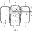
FIG. 2 is a cross-sectional view of a left side of a valve for an exhaust gas recirulation line according to an aspect of the present invention showing the valve in an open condition; -
FIG. 3 is a cross-sectional view of a left side of a valve for an exhaust gas recirculation line according to an aspect of the present invention showing the valve in a closed condition; -
FIG. 4 is a cross-sectional view of a right side of a valve for an exhaust gas recirulation line according to an aspect of the present invention showing the valve in an opencondition and -
FIG. 5 is a cross-sectional, perspective view of a left side of a valve for exhaust gas recirculation line according to an aspect of the present invention. - A
valve 21 for an exhaustgas recirculation line 23 in anengine 25 is provided as seen inFIG. 1 Theengine 25 comprises afirst group 27 of one ormore cylinders connected to afirst exhaust manifold 29 leading to afirst exhaust line 31 and asecond group 33 of one or more cylinders connected to asecond exhaust manifold 35 leading to asecond exhaust line 37. Such a configuration can be found, for example, in a straight six type engine wherein the first group of cylinders is the front three cylinders and the second group of cylinders is the rear three cylinders, however, the present invention is not limited to use in connection with such engines. Thefirst exhaust manifold 29 and thesecond exhaust manifold 35 may be separate manifolds connected only to thefirst group 27 and thesecond group 33 of one or more cylinders, respectively, or a single manifold that effectively functions to direct exhaust from the first group of one or more cylinders primarly to the first exhaust line and exhaust from the second group of one or more cylinders primarly to the second exhaust line. - The
first exhaust line 31 is connected to afirst barrel 39 of thevalve 21 and thesecond exhaust line 37 is connected to asecond barrel 41 of the valve. Thefirst barrel 39 has aninlet end 43 for receiving exhaust from thefirst group 27 of one or more cylinders, and thesecond barrel 41 has aninlet end 45 for receiving exhaust from thesecond group 33 of one or more cylinders. - A
center barrel 47 is disposed between thefirst barrel 39 and thesecond barrel 41 and has an outlet opening 49 for directing exhaust gas toward anintake 51 of the engine. thefirst barrel 39 and in inlet opening 53. Thesecond barrel 41 and thecenter barrel 47 are adapted to be in fluid communication through a second inlet opening 55. - As seen in
FIGS. 2 and3 , apoppet valve 57 comprising astem 59 and afirst valve head 61 and asecond valve head 63 mounted on the stem is provided. Thepoppet valve 57 further includes afirst valve seat 65 against which thefirst valve head 61 is arranged to be seated in thefirst barrel 39 around the first inlet opening 53, and asecond valve seat 67 against which thesecond valve head 63 is arranged to be seated in thecenter barrel 47 around the second inlet opening 55. Thefirst valve seat 65 and thesecond valve seat 67 may form part or all of the first inlet opening 53 and the second inlet opening 55, respectively. Thepoppet valve 57 is movable between a closed position as seen inFIG. 3 in which thefirst valve head 61 is seated against thefirst valve seat 65 and thesecond valve head 63 is seated against thesecond valve seat 67 and an open position as seen inFIG. 2 in wich the first valve head is moved in thefirst barel 39 away from the first valve seat and the second valve head is moved in thecenter barel 47 away from the second valve seat. Thepoppet valve 57 can be moved back and forth by any suitable means such as by a cam arrangement or by an actuator such as a solenoid. - The
center barrel 47 includes one ormore vanes 69 arranged to direct flow from the second inlet opening 55 toward the outlet opening 49. Each of thevanes 69 comprises afirst end 71 and asecond end 73, the first end being closer to the second inlet opening 55 than the first inlet opening 53 and the second end being closer to the outlet opening 49 than the first inlet opening. Each of thevanes 69 typically comprises a continuously curved portion between thefirst end 71 and thesecond end 73. A line L1 tangent to thefirst end 71 is ordinarily substantially parallel, i.e., between about 0° and 10°, to a longitudinal axis AS of thestem 59. A line L2 tangent to thesecond end 73 ordinarily defines an angle between 10° and 90° to the longitudinal axis AS of thestem 59, more preferably between 20° and 50° to : the longitudinal axis of the stem, and more preferably about 30°. - It is presently understood that increasing the curve radius of the vanes 69 (Le making them more curved) decreases the sequential total pressure loss in the
center barrel 47 due to the change of the direction of the fluid flow from thesecond opening 55. The curvature of thevanes 69 modulates the momentum of the fluid flow in the center barrel to more advantageously balance the pressure losses between flow along the curving vanes and flow impinging on what shall be referred to as the vertical ortop wall 75 of thecenter barrel 47. Preferably, parameters controlling the balance are selected such that the wall flow, after it has impinged against thetop wall 75, mainly heads in what shall be referred to as a downward direction toward the outlet opening 49 in order to minimize loss of the total pressure. Optimal selection of the dimensions, shape, and/or relative positionning of thesteering vanes 69 is likely to vary from application to application but are preferably made such that the momentum of the EGR wall flow is prfeserved as much as possible on its way from the second valve opening 55 in a gradually downward direction toward the outlet opening 49 following the curving shape of the steering vanes. - Typically, the
center barrel 49 comprises two ormore vanes 69. As seen inFIGS. 2 and3 , thevanes 69 can all have the same general ship. As seen in phantom inFIG.3 , however, the vanes can be configured so that a line L2a tangent to asecond end 73a of at least one 69a of the two or more vanes forms a different angle to the longitudinal axis AS of the stem than a line L2 tangent to asecond end 73 of at least one other one 69 of the two or more vanes. - The one or
more vanes 69 can be integrally formed with thecenter barrel 47, such as by being formed together as a cast or molded part, or by deforming a previously formed center barrel. Alternatively, the one ormore vanes 69 can be formed separatley from thecenter barrel 47 and attached to the center barrel by any suitable means, such as by welding or brazing or by mating male and female parts provided on the vanes and the center barrel. - As seen in
FIG. 5 , thecenter barrel 47, thefirst barel 39,and thesecond barrel 41 typically have a substantially circular or rounded shape when viewed along the longitudinal axis of thestem 59 and are generally cylindrical, excluding the protions of the first and second barrels constituting theinlet ends center barrel 47 caused by fluid flow exiting the second inlet opening that is directed upward toward thetop wall 75 having its direction reversed so that it will then flow toward the outlet opening 49. Provision of thevanes 69 further facilitates minimizing dead zones and pressure drop. The downstream side of thesecond valve head 63 can be curved as shown in phantom inFIGS. 2 and3 instead of forming a sharp edge to reduce turbulence in the center barrel and facilitate flow toward the outlet opening 49. - As seen in
FIGS. 2-4 , thecenter barrel 47 has a firstinterior surface 77 in which thefirst inlet opening 53 is provided, a secondinterior surface 79 in which thesecondinlet opening 55 is provided, a topside interior surface 75 between the first interior surface and the second interior surfece and opposite the outlet opening, and a left interior surface 81 (FIGS. 2 and3 ) and a right interior surface 83 (FIG. 4 ) between the first interior surface and the second interior surface and between the top interior surface and the outlet opening 49. The one ormore vanes 69 are provided in at least one of the leftinterior surface 81 and theright interior surface 83, typically both, and, typically, no vanes are provided in thetop surface 75. As seen by comparingFIGS. 2 and3 withFIG. 4 , when one ormore vanes 69 are provided in both of the leftinterior surface 81 and theright interior surface 83, the one or more vanes in the left interior surface are typically mirror images of the one or more vanes in the right interior surface. When a plurality ofvanes 69 are provided in the at least one of the left will typically be spaced in the at least one of the leftinterior surface 79 and the right interior surface over an are between 30° and 120° around the stem in each surface. - The
vanes 69 will extend radially inward from the at least one of the leftinterior surface 81 and the rightinterior surface 83 by an amount sufficient to provide a positive effect on flow. The height of thevanes 69 above the at least one of the leftinterior surface 81 and the rightinterior surface 83 will vary from valve to valve, however, it is presently anticipated that the vanes will typically be between about 5 mm and 15mm.
Claims (15)
- A valve (21) for an exhaust gas recirculation line (23) in an engine (25), comprising:a first barrel (39) having an inlet end (43) for receiving exhaust from a first group (27) of one or more cylinders;a second barrel (41) having an inlet end (45) for receiving exhaust from a second group (33) of one or more cylinders;a center barrel (47) disposed between the first barrel (39) and the second barrel (41) and having an outlet opening (49) for directing exhaust gas toward an intake of the engine, the first barrel (39) and the center barrel (47) being adapted to be in fluid communication through a first inlet opening (53), and the second barrel (41) and the center barrel (47) being adapted to be in fluid communication through a second inlet opening (55); anda poppet valve (57) comprising a stem (59) and a first valve head (61) and a second valve head (63) mounted on the stem (59), a first valve seat (65) against which the first valve head (63) is arranged to be seated in the first barrel (39) around the first inlet opening (53), and a second valve seat (67) against which the second valve head (63) is arranged to be seated in the center barrel (47) around the second inlet opening (55), the poppet valve (57) being movable between a closed position in which the first valve head (61) is seated against the first valve seat (65) and the second valve head (63) is seated against the second valve seat (67) and an open position in which the first valve head (63) is moved in the first barrel (39) away from the first valve seat (65) and the second valve head (63) is moved in the center barrel (47) away from the second valve seat (67),
characterized in that
the center barrel (47) includes one or more vanes (69) arranged to direct flow from the second inlet opening (55) toward the outlet opening (49). - The valve as set forth in claim 1, wherein the one or more vanes (69) each comprises a first end (71) and a second end (73), the first end (71) being closer to the second inlet opening (55) than the first inlet opening (53) and the second end (73) being closer to the outlet opening (49) than the first inlet opening (53).
- The valve as set forth in claim 2, wherein the one or more vanes (69) each comprises a continuously curved portion between the first end (71) and the second end (73).
- The valve as set forth in claim 2, wherein a line (L1) tangent to the first end (71) is substantially parallel to a longitudinal axis (AS) of the stem (59).
- The valve as set forth in claim 4, wherein a line (L2) tangent to the second end (73) defines an angle between 10° and 90° to the longitudinal axis (AS) of the stem (59).
- The valve as set forth in claim 5, wherein the line (L2) tangent to the second end (73) defines an angle between 20° and 50° to the longitudinal axis (AS) of the stem (59).
- The valve as set forth in claim 5, wherein the center barrel comprises two or more vanes (69), a line (L2a) tangent to a second end (73a) of at least one (69a) of the two or more vanes forming a different angle to the longitudinal axis (AS) of the stem (59) than a line (L2) tangent to a second end (73) of at least one other one (69) of the two or more vanes.
- The valve as set forth in claim 1, wherein the one or more vanes (69) are integrally formed with the center barrel (47).
- The valve as set forth in claim 1, wherein the one or more vanes (69) are formed separately from the center barrel (47) and attached to the center barrel (47).
- The valve as set forth in claim 1, wherein the center barrel (47) comprises two or more vanes (69).
- The valve as set forth in claim 10, wherein a line (L2a) tangent to a second end (73a) of at least one (69a) of the two or more vanes forms a different angle to the longitudinal axis (AS) of the stem (59) than a line (L2) tangent to a second end (73) of at least one other (69) of the two or more vanes.
- The valve as set forth in claim 10, wherein a line (L2) tangent to a second end (73) of each of the two or more vanes (69) forms a same angle to the longitudinal axis (AS) of the stem (59).
- The valve as set forth in claim 1, wherein the center barrel (47) has a substantially circular shape.
- The valve as set forth in claim 1, wherein the center barrel (47) has a first interior surface (77) in which the first inlet opening (53) is provided, a second interior surface (79) in which the second inlet opening (55) is provided, a top side interior surface (75) between the first interior surface (77) and the second interior surface (79) and opposite the outlet opening (49), and a left interior surface (81) and a right interior surface (83) between the first interior surface (77) and the second interior surface (79) and between the top interior surface (75) and the outlet opening (49), and wherein one or more vanes (69) is provided in at least one of the left interior surface (81) and the right interior surface (83).
- The valve as set forth in claim 14, wherein one or more vanes (69) is provided in both of the left interior surface (81) and the right interior surface (83).
Applications Claiming Priority (1)
| Application Number | Priority Date | Filing Date | Title |
|---|---|---|---|
| PCT/US2017/046841 WO2019035806A1 (en) | 2017-08-15 | 2017-08-15 | Vaned valve for exhaust gas recirculation line |
Publications (3)
| Publication Number | Publication Date |
|---|---|
| EP3669064A1 EP3669064A1 (en) | 2020-06-24 |
| EP3669064A4 EP3669064A4 (en) | 2020-12-09 |
| EP3669064B1 true EP3669064B1 (en) | 2021-04-21 |
Family
ID=65362472
Family Applications (1)
| Application Number | Title | Priority Date | Filing Date |
|---|---|---|---|
| EP17921891.2A Active EP3669064B1 (en) | 2017-08-15 | 2017-08-15 | Vaned valve for exhaust gas recirculation line |
Country Status (4)
| Country | Link |
|---|---|
| US (1) | US11441521B2 (en) |
| EP (1) | EP3669064B1 (en) |
| CN (1) | CN111094733B (en) |
| WO (1) | WO2019035806A1 (en) |
Family Cites Families (25)
| Publication number | Priority date | Publication date | Assignee | Title |
|---|---|---|---|---|
| US3263906A (en) | 1963-07-22 | 1966-08-02 | Task Corp | Stator vane check valve |
| US4823743A (en) | 1986-06-17 | 1989-04-25 | Compression Technology Inc. | Oscillating vane machine |
| JP3331526B2 (en) * | 1993-11-25 | 2002-10-07 | フジオーゼックス株式会社 | Poppet valve drive |
| US5662079A (en) * | 1994-06-27 | 1997-09-02 | Snider; John Michael | Manifold flow turning vanes in internal combustion engines |
| CN1066517C (en) | 1995-05-22 | 2001-05-30 | 富士乌兹克斯株式会社 | Poppet valve device |
| ATE246036T1 (en) | 1996-04-12 | 2003-08-15 | Sulzer Chemtech Ag | MIXING TUBE FOR LOW VISCOSITY FLUIDS |
| US6006732A (en) * | 1998-09-03 | 1999-12-28 | Navistar International Transportation Corp | Balanced flow EGR control apparatus |
| US6089019A (en) * | 1999-01-15 | 2000-07-18 | Borgwarner Inc. | Turbocharger and EGR system |
| WO2002043846A1 (en) * | 1999-06-17 | 2002-06-06 | Ohr Co., Ltd. | Cavitation generating device and fluid mixing device using the device |
| US6904897B1 (en) | 2004-03-05 | 2005-06-14 | Siemens Vdo Automotive Inc. | Bearing porosity control in an exhaust gas recirculation valve |
| US20060081228A1 (en) | 2004-10-19 | 2006-04-20 | Borgwarner Inc. | Exhaust gas recirculation valve and poppet |
| JP2006233859A (en) | 2005-02-24 | 2006-09-07 | Toyota Industries Corp | Intake device for engine |
| KR20070010362A (en) | 2005-07-18 | 2007-01-24 | 현대자동차주식회사 | EBR valve structure |
| JP2007303434A (en) | 2006-05-15 | 2007-11-22 | Denso Corp | Exhaust gas control valve |
| US7845340B2 (en) | 2006-12-22 | 2010-12-07 | Cummins Inc. | Air-exhaust mixing apparatus |
| US20110305103A1 (en) | 2010-06-15 | 2011-12-15 | Mcguire Dennis | Hydrodynamic cavitation device |
| RU2560863C2 (en) | 2010-12-20 | 2015-08-20 | Мак Тракс, Инк. | Inserted valve assembly of spent gases recirculation system |
| DE102012101851B4 (en) | 2012-03-06 | 2014-06-05 | Pierburg Gmbh | Abgaseinleitvorrichtung for an internal combustion engine |
| CN102600743A (en) | 2012-03-27 | 2012-07-25 | 甘肃金桥给水排水设计与工程(集团)有限公司 | Static pipeline mixer |
| US9611756B2 (en) | 2012-11-02 | 2017-04-04 | General Electric Company | System and method for protecting components in a gas turbine engine with exhaust gas recirculation |
| US20140301157A1 (en) * | 2013-04-03 | 2014-10-09 | Westfall Manufacturing Company | Static Mixer |
| CA2857836A1 (en) | 2013-07-25 | 2015-01-25 | Michael Allan Isabelle | Paintball marker loading and feeding system |
| CN203584619U (en) | 2013-11-12 | 2014-05-07 | 联创汽车电子有限公司 | Exhaust gas recirculation valve |
| DE102015121616B4 (en) * | 2015-12-11 | 2018-06-14 | Ford-Werke Gmbh | Regulating device for an internal combustion engine |
| DE102015121617B4 (en) * | 2015-12-11 | 2021-01-28 | Ford-Werke Gmbh | Control device for an internal combustion engine |
-
2017
- 2017-08-15 EP EP17921891.2A patent/EP3669064B1/en active Active
- 2017-08-15 WO PCT/US2017/046841 patent/WO2019035806A1/en not_active Ceased
- 2017-08-15 CN CN201780092582.2A patent/CN111094733B/en not_active Expired - Fee Related
- 2017-08-15 US US16/627,309 patent/US11441521B2/en active Active
Also Published As
| Publication number | Publication date |
|---|---|
| CN111094733B (en) | 2021-11-16 |
| US20200173400A1 (en) | 2020-06-04 |
| CN111094733A (en) | 2020-05-01 |
| US11441521B2 (en) | 2022-09-13 |
| EP3669064A4 (en) | 2020-12-09 |
| EP3669064A1 (en) | 2020-06-24 |
| WO2019035806A1 (en) | 2019-02-21 |
Similar Documents
| Publication | Publication Date | Title |
|---|---|---|
| EP2796685B1 (en) | Exhaust gas heat recovery device | |
| CN104114922A (en) | Check valve with flexible membrane | |
| JPH05500997A (en) | Improved intake valve for internal combustion engines | |
| GB2043779A (en) | Internal combustion engine exhaust passage | |
| US4537028A (en) | Exhaust port | |
| JP6639119B2 (en) | Intake manifold for internal combustion engine | |
| EP3669064B1 (en) | Vaned valve for exhaust gas recirculation line | |
| US4343268A (en) | Energy conserving exhaust passage for an internal combustion engine | |
| US20170241329A1 (en) | Engine supercharger | |
| CN104975925A (en) | Exhaust manifold for an internal combustion engine, particularly in motor vehicles | |
| JPS6060009B2 (en) | Intake system for multi-cylinder internal combustion engine | |
| EP3303793B1 (en) | Exhaust manifold | |
| JP4916380B2 (en) | Intake manifold for internal combustion engines | |
| US3557766A (en) | Combustion engines | |
| JP2011247270A (en) | Port structure of internal combustion engine | |
| CN204572184U (en) | Admission line | |
| US10655558B2 (en) | Internal combustion engine | |
| JP7139958B2 (en) | Intake manifold | |
| US9109543B2 (en) | Exhaust manifold for an internal combustion engine, in particular in motor vehicles | |
| US7607412B2 (en) | Air supply distributor for an internal combustion engine | |
| JP7384110B2 (en) | intake device | |
| CN113404568B (en) | Integral intake valve, cylinder head and gas engine | |
| JP3387193B2 (en) | Exhaust gas recirculation device | |
| JPH08158873A (en) | Multi-valve intake engine | |
| JP4888460B2 (en) | Port structure of internal combustion engine |
Legal Events
| Date | Code | Title | Description |
|---|---|---|---|
| STAA | Information on the status of an ep patent application or granted ep patent |
Free format text: STATUS: THE INTERNATIONAL PUBLICATION HAS BEEN MADE |
|
| PUAI | Public reference made under article 153(3) epc to a published international application that has entered the european phase |
Free format text: ORIGINAL CODE: 0009012 |
|
| STAA | Information on the status of an ep patent application or granted ep patent |
Free format text: STATUS: REQUEST FOR EXAMINATION WAS MADE |
|
| 17P | Request for examination filed |
Effective date: 20200207 |
|
| AK | Designated contracting states |
Kind code of ref document: A1 Designated state(s): AL AT BE BG CH CY CZ DE DK EE ES FI FR GB GR HR HU IE IS IT LI LT LU LV MC MK MT NL NO PL PT RO RS SE SI SK SM TR |
|
| AX | Request for extension of the european patent |
Extension state: BA ME |
|
| REG | Reference to a national code |
Ref country code: DE Ref legal event code: R079 Ref document number: 602017037398 Country of ref document: DE Free format text: PREVIOUS MAIN CLASS: F02M0026370000 Ipc: F02M0026660000 |
|
| DAV | Request for validation of the european patent (deleted) | ||
| DAX | Request for extension of the european patent (deleted) | ||
| A4 | Supplementary search report drawn up and despatched |
Effective date: 20201111 |
|
| RIC1 | Information provided on ipc code assigned before grant |
Ipc: F02M 26/71 20160101ALI20201105BHEP Ipc: F02M 26/69 20160101ALI20201105BHEP Ipc: F02M 26/66 20160101AFI20201105BHEP Ipc: F02M 26/68 20160101ALI20201105BHEP Ipc: F16K 47/08 20060101ALI20201105BHEP Ipc: F16K 11/16 20060101ALI20201105BHEP |
|
| GRAP | Despatch of communication of intention to grant a patent |
Free format text: ORIGINAL CODE: EPIDOSNIGR1 |
|
| STAA | Information on the status of an ep patent application or granted ep patent |
Free format text: STATUS: GRANT OF PATENT IS INTENDED |
|
| GRAS | Grant fee paid |
Free format text: ORIGINAL CODE: EPIDOSNIGR3 |
|
| INTG | Intention to grant announced |
Effective date: 20210215 |
|
| GRAA | (expected) grant |
Free format text: ORIGINAL CODE: 0009210 |
|
| STAA | Information on the status of an ep patent application or granted ep patent |
Free format text: STATUS: THE PATENT HAS BEEN GRANTED |
|
| AK | Designated contracting states |
Kind code of ref document: B1 Designated state(s): AL AT BE BG CH CY CZ DE DK EE ES FI FR GB GR HR HU IE IS IT LI LT LU LV MC MK MT NL NO PL PT RO RS SE SI SK SM TR |
|
| REG | Reference to a national code |
Ref country code: GB Ref legal event code: FG4D |
|
| REG | Reference to a national code |
Ref country code: CH Ref legal event code: EP |
|
| REG | Reference to a national code |
Ref country code: DE Ref legal event code: R096 Ref document number: 602017037398 Country of ref document: DE |
|
| REG | Reference to a national code |
Ref country code: IE Ref legal event code: FG4D |
|
| REG | Reference to a national code |
Ref country code: AT Ref legal event code: REF Ref document number: 1384880 Country of ref document: AT Kind code of ref document: T Effective date: 20210515 |
|
| REG | Reference to a national code |
Ref country code: LT Ref legal event code: MG9D |
|
| REG | Reference to a national code |
Ref country code: AT Ref legal event code: MK05 Ref document number: 1384880 Country of ref document: AT Kind code of ref document: T Effective date: 20210421 |
|
| REG | Reference to a national code |
Ref country code: NL Ref legal event code: MP Effective date: 20210421 |
|
| PG25 | Lapsed in a contracting state [announced via postgrant information from national office to epo] |
Ref country code: LT Free format text: LAPSE BECAUSE OF FAILURE TO SUBMIT A TRANSLATION OF THE DESCRIPTION OR TO PAY THE FEE WITHIN THE PRESCRIBED TIME-LIMIT Effective date: 20210421 Ref country code: FI Free format text: LAPSE BECAUSE OF FAILURE TO SUBMIT A TRANSLATION OF THE DESCRIPTION OR TO PAY THE FEE WITHIN THE PRESCRIBED TIME-LIMIT Effective date: 20210421 Ref country code: HR Free format text: LAPSE BECAUSE OF FAILURE TO SUBMIT A TRANSLATION OF THE DESCRIPTION OR TO PAY THE FEE WITHIN THE PRESCRIBED TIME-LIMIT Effective date: 20210421 Ref country code: BG Free format text: LAPSE BECAUSE OF FAILURE TO SUBMIT A TRANSLATION OF THE DESCRIPTION OR TO PAY THE FEE WITHIN THE PRESCRIBED TIME-LIMIT Effective date: 20210721 Ref country code: AT Free format text: LAPSE BECAUSE OF FAILURE TO SUBMIT A TRANSLATION OF THE DESCRIPTION OR TO PAY THE FEE WITHIN THE PRESCRIBED TIME-LIMIT Effective date: 20210421 Ref country code: NL Free format text: LAPSE BECAUSE OF FAILURE TO SUBMIT A TRANSLATION OF THE DESCRIPTION OR TO PAY THE FEE WITHIN THE PRESCRIBED TIME-LIMIT Effective date: 20210421 |
|
| PG25 | Lapsed in a contracting state [announced via postgrant information from national office to epo] |
Ref country code: PT Free format text: LAPSE BECAUSE OF FAILURE TO SUBMIT A TRANSLATION OF THE DESCRIPTION OR TO PAY THE FEE WITHIN THE PRESCRIBED TIME-LIMIT Effective date: 20210823 Ref country code: PL Free format text: LAPSE BECAUSE OF FAILURE TO SUBMIT A TRANSLATION OF THE DESCRIPTION OR TO PAY THE FEE WITHIN THE PRESCRIBED TIME-LIMIT Effective date: 20210421 Ref country code: LV Free format text: LAPSE BECAUSE OF FAILURE TO SUBMIT A TRANSLATION OF THE DESCRIPTION OR TO PAY THE FEE WITHIN THE PRESCRIBED TIME-LIMIT Effective date: 20210421 Ref country code: NO Free format text: LAPSE BECAUSE OF FAILURE TO SUBMIT A TRANSLATION OF THE DESCRIPTION OR TO PAY THE FEE WITHIN THE PRESCRIBED TIME-LIMIT Effective date: 20210721 Ref country code: SE Free format text: LAPSE BECAUSE OF FAILURE TO SUBMIT A TRANSLATION OF THE DESCRIPTION OR TO PAY THE FEE WITHIN THE PRESCRIBED TIME-LIMIT Effective date: 20210421 Ref country code: RS Free format text: LAPSE BECAUSE OF FAILURE TO SUBMIT A TRANSLATION OF THE DESCRIPTION OR TO PAY THE FEE WITHIN THE PRESCRIBED TIME-LIMIT Effective date: 20210421 Ref country code: GR Free format text: LAPSE BECAUSE OF FAILURE TO SUBMIT A TRANSLATION OF THE DESCRIPTION OR TO PAY THE FEE WITHIN THE PRESCRIBED TIME-LIMIT Effective date: 20210722 Ref country code: IS Free format text: LAPSE BECAUSE OF FAILURE TO SUBMIT A TRANSLATION OF THE DESCRIPTION OR TO PAY THE FEE WITHIN THE PRESCRIBED TIME-LIMIT Effective date: 20210821 |
|
| REG | Reference to a national code |
Ref country code: DE Ref legal event code: R097 Ref document number: 602017037398 Country of ref document: DE |
|
| PG25 | Lapsed in a contracting state [announced via postgrant information from national office to epo] |
Ref country code: CZ Free format text: LAPSE BECAUSE OF FAILURE TO SUBMIT A TRANSLATION OF THE DESCRIPTION OR TO PAY THE FEE WITHIN THE PRESCRIBED TIME-LIMIT Effective date: 20210421 Ref country code: DK Free format text: LAPSE BECAUSE OF FAILURE TO SUBMIT A TRANSLATION OF THE DESCRIPTION OR TO PAY THE FEE WITHIN THE PRESCRIBED TIME-LIMIT Effective date: 20210421 Ref country code: RO Free format text: LAPSE BECAUSE OF FAILURE TO SUBMIT A TRANSLATION OF THE DESCRIPTION OR TO PAY THE FEE WITHIN THE PRESCRIBED TIME-LIMIT Effective date: 20210421 Ref country code: EE Free format text: LAPSE BECAUSE OF FAILURE TO SUBMIT A TRANSLATION OF THE DESCRIPTION OR TO PAY THE FEE WITHIN THE PRESCRIBED TIME-LIMIT Effective date: 20210421 Ref country code: ES Free format text: LAPSE BECAUSE OF FAILURE TO SUBMIT A TRANSLATION OF THE DESCRIPTION OR TO PAY THE FEE WITHIN THE PRESCRIBED TIME-LIMIT Effective date: 20210421 Ref country code: SM Free format text: LAPSE BECAUSE OF FAILURE TO SUBMIT A TRANSLATION OF THE DESCRIPTION OR TO PAY THE FEE WITHIN THE PRESCRIBED TIME-LIMIT Effective date: 20210421 Ref country code: SK Free format text: LAPSE BECAUSE OF FAILURE TO SUBMIT A TRANSLATION OF THE DESCRIPTION OR TO PAY THE FEE WITHIN THE PRESCRIBED TIME-LIMIT Effective date: 20210421 |
|
| PLBE | No opposition filed within time limit |
Free format text: ORIGINAL CODE: 0009261 |
|
| STAA | Information on the status of an ep patent application or granted ep patent |
Free format text: STATUS: NO OPPOSITION FILED WITHIN TIME LIMIT |
|
| 26N | No opposition filed |
Effective date: 20220124 |
|
| REG | Reference to a national code |
Ref country code: CH Ref legal event code: PL |
|
| PG25 | Lapsed in a contracting state [announced via postgrant information from national office to epo] |
Ref country code: MC Free format text: LAPSE BECAUSE OF FAILURE TO SUBMIT A TRANSLATION OF THE DESCRIPTION OR TO PAY THE FEE WITHIN THE PRESCRIBED TIME-LIMIT Effective date: 20210421 |
|
| REG | Reference to a national code |
Ref country code: BE Ref legal event code: MM Effective date: 20210831 |
|
| GBPC | Gb: european patent ceased through non-payment of renewal fee |
Effective date: 20210815 |
|
| PG25 | Lapsed in a contracting state [announced via postgrant information from national office to epo] |
Ref country code: CH Free format text: LAPSE BECAUSE OF NON-PAYMENT OF DUE FEES Effective date: 20210831 Ref country code: LI Free format text: LAPSE BECAUSE OF NON-PAYMENT OF DUE FEES Effective date: 20210831 |
|
| PG25 | Lapsed in a contracting state [announced via postgrant information from national office to epo] |
Ref country code: IS Free format text: LAPSE BECAUSE OF FAILURE TO SUBMIT A TRANSLATION OF THE DESCRIPTION OR TO PAY THE FEE WITHIN THE PRESCRIBED TIME-LIMIT Effective date: 20210821 Ref country code: LU Free format text: LAPSE BECAUSE OF NON-PAYMENT OF DUE FEES Effective date: 20210815 Ref country code: AL Free format text: LAPSE BECAUSE OF FAILURE TO SUBMIT A TRANSLATION OF THE DESCRIPTION OR TO PAY THE FEE WITHIN THE PRESCRIBED TIME-LIMIT Effective date: 20210421 |
|
| PG25 | Lapsed in a contracting state [announced via postgrant information from national office to epo] |
Ref country code: IT Free format text: LAPSE BECAUSE OF FAILURE TO SUBMIT A TRANSLATION OF THE DESCRIPTION OR TO PAY THE FEE WITHIN THE PRESCRIBED TIME-LIMIT Effective date: 20210421 Ref country code: GB Free format text: LAPSE BECAUSE OF NON-PAYMENT OF DUE FEES Effective date: 20210815 Ref country code: BE Free format text: LAPSE BECAUSE OF NON-PAYMENT OF DUE FEES Effective date: 20210831 Ref country code: IE Free format text: LAPSE BECAUSE OF NON-PAYMENT OF DUE FEES Effective date: 20210815 |
|
| PGFP | Annual fee paid to national office [announced via postgrant information from national office to epo] |
Ref country code: DE Payment date: 20220527 Year of fee payment: 6 |
|
| PGFP | Annual fee paid to national office [announced via postgrant information from national office to epo] |
Ref country code: FR Payment date: 20220824 Year of fee payment: 6 |
|
| PG25 | Lapsed in a contracting state [announced via postgrant information from national office to epo] |
Ref country code: CY Free format text: LAPSE BECAUSE OF FAILURE TO SUBMIT A TRANSLATION OF THE DESCRIPTION OR TO PAY THE FEE WITHIN THE PRESCRIBED TIME-LIMIT Effective date: 20210421 |
|
| PG25 | Lapsed in a contracting state [announced via postgrant information from national office to epo] |
Ref country code: HU Free format text: LAPSE BECAUSE OF FAILURE TO SUBMIT A TRANSLATION OF THE DESCRIPTION OR TO PAY THE FEE WITHIN THE PRESCRIBED TIME-LIMIT; INVALID AB INITIO Effective date: 20170815 |
|
| REG | Reference to a national code |
Ref country code: DE Ref legal event code: R119 Ref document number: 602017037398 Country of ref document: DE |
|
| PG25 | Lapsed in a contracting state [announced via postgrant information from national office to epo] |
Ref country code: MK Free format text: LAPSE BECAUSE OF FAILURE TO SUBMIT A TRANSLATION OF THE DESCRIPTION OR TO PAY THE FEE WITHIN THE PRESCRIBED TIME-LIMIT Effective date: 20210421 |
|
| PG25 | Lapsed in a contracting state [announced via postgrant information from national office to epo] |
Ref country code: FR Free format text: LAPSE BECAUSE OF NON-PAYMENT OF DUE FEES Effective date: 20230831 Ref country code: DE Free format text: LAPSE BECAUSE OF NON-PAYMENT OF DUE FEES Effective date: 20240301 |
|
| PG25 | Lapsed in a contracting state [announced via postgrant information from national office to epo] |
Ref country code: MT Free format text: LAPSE BECAUSE OF FAILURE TO SUBMIT A TRANSLATION OF THE DESCRIPTION OR TO PAY THE FEE WITHIN THE PRESCRIBED TIME-LIMIT Effective date: 20210421 |
|
| PG25 | Lapsed in a contracting state [announced via postgrant information from national office to epo] |
Ref country code: TR Free format text: LAPSE BECAUSE OF FAILURE TO SUBMIT A TRANSLATION OF THE DESCRIPTION OR TO PAY THE FEE WITHIN THE PRESCRIBED TIME-LIMIT Effective date: 20210421 |