EP3668253B1 - Procédés et dispositifs de transmission de données - Google Patents
Procédés et dispositifs de transmission de données Download PDFInfo
- Publication number
- EP3668253B1 EP3668253B1 EP17922883.8A EP17922883A EP3668253B1 EP 3668253 B1 EP3668253 B1 EP 3668253B1 EP 17922883 A EP17922883 A EP 17922883A EP 3668253 B1 EP3668253 B1 EP 3668253B1
- Authority
- EP
- European Patent Office
- Prior art keywords
- rlc entity
- data transmission
- pdcp packet
- indication message
- packet duplication
- Prior art date
- Legal status (The legal status is an assumption and is not a legal conclusion. Google has not performed a legal analysis and makes no representation as to the accuracy of the status listed.)
- Active
Links
- 230000005540 biological transmission Effects 0.000 title claims description 337
- 238000000034 method Methods 0.000 title claims description 55
- 230000006870 function Effects 0.000 claims description 228
- 230000009849 deactivation Effects 0.000 claims description 10
- 230000011664 signaling Effects 0.000 claims description 4
- 238000010586 diagram Methods 0.000 description 18
- 238000004891 communication Methods 0.000 description 10
- 230000004913 activation Effects 0.000 description 6
- 238000005516 engineering process Methods 0.000 description 6
- 238000004590 computer program Methods 0.000 description 4
- 230000003287 optical effect Effects 0.000 description 4
- 230000005236 sound signal Effects 0.000 description 4
- 239000000969 carrier Substances 0.000 description 3
- 238000007726 management method Methods 0.000 description 3
- 230000001133 acceleration Effects 0.000 description 2
- 230000009471 action Effects 0.000 description 2
- 230000008859 change Effects 0.000 description 2
- 230000003993 interaction Effects 0.000 description 2
- 238000013507 mapping Methods 0.000 description 2
- 230000002093 peripheral effect Effects 0.000 description 2
- 238000003491 array Methods 0.000 description 1
- 230000000295 complement effect Effects 0.000 description 1
- 238000013500 data storage Methods 0.000 description 1
- 238000003384 imaging method Methods 0.000 description 1
- 239000004973 liquid crystal related substance Substances 0.000 description 1
- 230000007774 longterm Effects 0.000 description 1
- 229910044991 metal oxide Inorganic materials 0.000 description 1
- 150000004706 metal oxides Chemical class 0.000 description 1
- 230000008569 process Effects 0.000 description 1
- 239000004065 semiconductor Substances 0.000 description 1
- 230000003068 static effect Effects 0.000 description 1
Images


Classifications
-
- H—ELECTRICITY
- H04—ELECTRIC COMMUNICATION TECHNIQUE
- H04W—WIRELESS COMMUNICATION NETWORKS
- H04W80/00—Wireless network protocols or protocol adaptations to wireless operation
- H04W80/04—Network layer protocols, e.g. mobile IP [Internet Protocol]
-
- H—ELECTRICITY
- H04—ELECTRIC COMMUNICATION TECHNIQUE
- H04W—WIRELESS COMMUNICATION NETWORKS
- H04W76/00—Connection management
- H04W76/10—Connection setup
- H04W76/15—Setup of multiple wireless link connections
-
- H—ELECTRICITY
- H04—ELECTRIC COMMUNICATION TECHNIQUE
- H04L—TRANSMISSION OF DIGITAL INFORMATION, e.g. TELEGRAPHIC COMMUNICATION
- H04L5/00—Arrangements affording multiple use of the transmission path
- H04L5/003—Arrangements for allocating sub-channels of the transmission path
- H04L5/0053—Allocation of signaling, i.e. of overhead other than pilot signals
-
- H—ELECTRICITY
- H04—ELECTRIC COMMUNICATION TECHNIQUE
- H04L—TRANSMISSION OF DIGITAL INFORMATION, e.g. TELEGRAPHIC COMMUNICATION
- H04L1/00—Arrangements for detecting or preventing errors in the information received
- H04L1/0001—Systems modifying transmission characteristics according to link quality, e.g. power backoff
- H04L1/0006—Systems modifying transmission characteristics according to link quality, e.g. power backoff by adapting the transmission format
-
- H—ELECTRICITY
- H04—ELECTRIC COMMUNICATION TECHNIQUE
- H04W—WIRELESS COMMUNICATION NETWORKS
- H04W28/00—Network traffic management; Network resource management
- H04W28/02—Traffic management, e.g. flow control or congestion control
- H04W28/0252—Traffic management, e.g. flow control or congestion control per individual bearer or channel
-
- H—ELECTRICITY
- H04—ELECTRIC COMMUNICATION TECHNIQUE
- H04W—WIRELESS COMMUNICATION NETWORKS
- H04W28/00—Network traffic management; Network resource management
- H04W28/02—Traffic management, e.g. flow control or congestion control
- H04W28/06—Optimizing the usage of the radio link, e.g. header compression, information sizing, discarding information
-
- H—ELECTRICITY
- H04—ELECTRIC COMMUNICATION TECHNIQUE
- H04W—WIRELESS COMMUNICATION NETWORKS
- H04W76/00—Connection management
- H04W76/10—Connection setup
-
- H—ELECTRICITY
- H04—ELECTRIC COMMUNICATION TECHNIQUE
- H04W—WIRELESS COMMUNICATION NETWORKS
- H04W76/00—Connection management
- H04W76/10—Connection setup
- H04W76/12—Setup of transport tunnels
-
- H—ELECTRICITY
- H04—ELECTRIC COMMUNICATION TECHNIQUE
- H04W—WIRELESS COMMUNICATION NETWORKS
- H04W76/00—Connection management
- H04W76/20—Manipulation of established connections
-
- H—ELECTRICITY
- H04—ELECTRIC COMMUNICATION TECHNIQUE
- H04W—WIRELESS COMMUNICATION NETWORKS
- H04W76/00—Connection management
- H04W76/20—Manipulation of established connections
- H04W76/27—Transitions between radio resource control [RRC] states
-
- H—ELECTRICITY
- H04—ELECTRIC COMMUNICATION TECHNIQUE
- H04W—WIRELESS COMMUNICATION NETWORKS
- H04W80/00—Wireless network protocols or protocol adaptations to wireless operation
- H04W80/02—Data link layer protocols
Definitions
- the present disclosure generally relates to the technical field of communications, and more particularly, to data transmission methods and devices.
- an RB in a Long Term Evolution (LTE) system is a set of logical radio resources.
- the RB refers to a bearer between User Equipment (UE) and a base station.
- the RB can be divided into a Signaling Radio Bearer (SRB) and a Data Radio Bearer (DRB) in terms of bearer contents.
- SRB Signaling Radio Bearer
- DRB Data Radio Bearer
- 5G 5th-Generation
- PDCP Packet Data Convergence Protocol
- embodiments of the present disclosure provide data transmission methods and devices, as described in the appending claims.
- indication information may also be called second information and, similarly, second information may also be called indication information.
- second information may also be called indication information.
- term “if” used here may be explained as “while” or “when” or “responsive to determining”, which depends on the context.
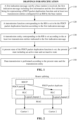
- FIG. 1 is a flowchart illustrating a data transmission method according to an exemplary embodiment, wherein, however, not all of the features required by the claimed invention are shown in FIG: 1 .
- the data transmission method is applied to a terminal. As shown in FIG. 1 , the data transmission method includes the following steps 110 to 150.
- a first indication message sent by a base station is received, the first indication message including first information and the first information being for representing a PDCP packet duplication function and at least two transmission entities configured for an RB by the base station.
- the RB may be an SRB or a DRB. Moreover, the RB may be a newly established SRB or DRB or may be an SRB or DRB that has been established.
- the base station after configuring the PDCP packet duplication function and transmission entities for the RB, indicates them to the terminal through the first indication message; and the terminal, after receiving the first indication message, learns a specific transmission function and transmission entities configured for the RB by the base station according to the first information in the first indication message.
- the PDCP packet duplication function refers to duplicating data of a PDCP layer to obtain a PDCP packet and a PDCP packet duplicate and sending them through two different RLC entities.
- combining PDCP packet duplication with carriers refers to mapping a PDCP layer to different logical channels through bearer splitting and further mapping the mapped PDCP layer to different physical carriers.
- the transmission entity refers to an RLC entity needed for implementation of the PDCP packet duplication function.
- a primary RLC entity and a secondary RLC entity are needed for implementation of the PDCP packet duplication function, and in such a case, the two RLC entities, i.e., the primary RLC entity and the secondary RLC entity, are configured for the RB.
- a transmission function corresponding to the RB is set to be the PDCP packet duplication function according to the first indication message.
- the terminal sets the PDCP packet duplication function for the RB according to a configuration of the base station.
- a transmission entity corresponding to the RB is set according to the at least two transmission entities indicated in the first indication message.
- the terminal sets the transmission entity corresponding to the RB according to a configuration of the base station. Responsive to that the base station configures two transmission entities, the terminal also sets two transmission entities.
- step 140 a present state of the PDCP packet duplication function is set, the present state including an active state and an inactive state.
- the terminal may set the present state of the PDCP packet duplication function according to a configuration of the base station and, in a case that there is no configuration of the base station, the terminal may also set the present state of the PDCP packet duplication function according to a system default initial state.
- step 150 data transmission is performed according to the present state of the PDCP packet duplication function and the transmission entity corresponding to the RB.
- a base station and a terminal are included.
- the base station configures a PDCP packet duplication function for an RB, configures at least two transmission entities configured to implement the PDCP packet duplication function, adds first information into a first indication message, the first information being for representing the PDCP packet duplication function and at least two transmission entities configured for the RB by the base station, and sends the first indication message to the terminal.
- the terminal receives first indication message, sets a transmission function corresponding to the RB to be the PDCP packet duplication function according to a configuration of the base station and sets a transmission entity corresponding to the RB according to a configuration of the base station, and further sets a present state of the PDCP packet duplication function and performs data transmission according to the present state and the transmission entity. Further features are required by the claimed invention.
- the terminal receives the first indication message from the base station; the first indication message includes the first information and the first information is for representing the PDCP packet duplication function and at least two transmission entities configured for the RB by the base station; the terminal sets the transmission function corresponding to the RB to be the PDCP packet duplication function according to the first indication message, sets the transmission entity corresponding to the RB according to the at least two transmission entities indicated in the first indication message, sets the present state of the PDCP packet duplication function, the present state including the active state and the inactive state, and performs data transmission according to the present state of the PDCP packet duplication function and the transmission entity corresponding to the RB, so that data transmission for the PDCP packet duplication function can be implemented, and the reliability of data transmission can be improved.
- the at least two transmission entities configured for the RB by the base station in step 110 include a primary RLC entity and a secondary RLC entity, and the terminal also needs to set the primary RLC entity and the secondary RLC entity for the RB.
- a setting process may include (1-1) and (1-2).
- a first RLC entity and a second RLC entity may be constructed, the first RLC entity may be set as the primary RLC entity, and the second RLC entity may be set as the secondary RLC entity.
- one RLC entity that has been constructed may be set as the primary RLC entity, and another RLC entity that has been constructed may be set as the secondary RLC entity.
- the terminal further sets a primary RLC entity and a secondary RLC entity corresponding to the RB according to the primary RLC entity and secondary RLC entity configured for the RB by the base station to satisfy the two transmission entities needed for implementation of the PDCP packet duplication function and transmits the PDCP packet and the PDCP packet duplicate through the two transmission entities, so that the speed of data transmission can be increased, the reliability of data transmission can be improved, and the low sending success rate can be improved when the PDCP packet and the PDCP packet duplicate are transmitted on the same transmission entity.
- the operation in step 140 that the present state of the PDCP packet duplication function is set may include at least one of the following setting manners, i.e., (2-1) or (2-2) or (2-3).
- the present state of the PDCP packet duplication function may be set as a system default initial state, the system default initial state including the active state or the inactive state.
- the present state of the PDCP packet duplication function in a case that the system default initial state is the active state, the present state of the PDCP packet duplication function may be set as the active state; and similarly, in a case that the system default initial state is the inactive state, the present state of the PDCP packet duplication function may be set as the inactive state.
- the first indication message further includes second information
- the second information is for representing an initial state, configured by the base station, of the PDCP packet duplication function and the initial state is the active state or the inactive state
- the present state of the PDCP packet duplication function may be set as the initial state, configured by the base station, of the PDCP packet duplication function according to the second information.
- the present state of the PDCP packet duplication function in a case that the initial state configured by the base station is the active state, the present state of the PDCP packet duplication function may be set as the active state; and similarly, in a case that the initial state configured by the base station is the inactive state, the present state of the PDCP packet duplication function is set as the inactive state, as according to the invention.
- the present state of the PDCP packet duplication function may be set as the active state according to the activation instruction. This is not covered by the claimed invention.
- the present state of the PDCP packet duplication function may be required to be set as the active state no matter in which state the PDCP packet duplication function was before.
- the priority of (2-3) is highest, that is, even though the present state of the PDCP packet duplication function has been set to be the inactive state, the present state of the PDCP packet duplication function is also required to be switched from the inactive state to the active state upon that the activation instruction for the PDCP packet duplication function is received from the base station.
- the priority of (2-1) is lowest, namely, the system default initial state is adopted only when no configuration of the base station is received.
- the present state of the PDCP packet duplication function may be set according to a configuration of the base station, and in a case that there is no configuration of the base station, the present state of the PDCP packet duplication function may also be set according to the system default initial state, so that subsequent data transmission according to the present state can be ensured, and diversity of data transmission can be improved.
- the present state of the PDCP packet duplication function is the inactive state, and the transmission entity corresponding to the RB includes the primary RLC entity and the secondary RLC entity.
- the transmission entity corresponding to the RB includes the primary RLC entity and the secondary RLC entity.
- the RB may be a newly established SRB or DRB.
- PDCP may send a Packet Data Unit (PDU) through the primary RLC entity, namely, a size of data that can be sent may be indicated through the PDCP to a logical channel corresponding to the primary RLC entity.
- PDU Packet Data Unit
- the RB may be an SRB or DRB that has been established.
- At least one of following data transmission manners may be further included, i.e., (3-1) or (3-2) or (3-3) or (3-4), wherein (3-1) and (3-3) are required by the claimed invention, and (3-2) and (3-4) are not according to the claimed invention.
- (3-1) Data transmission for data that is not delivered to an RLC layer is performed by use of the primary RLC entity and data transmission for data that has been delivered to the secondary RLC entity is continued to be performed by use of the secondary RLC entity.
- the PDCP may send a subsequent PDU (PDU that has not yet been delivered to the RLC layer) through the primary RLC entity, and a PDCU that has been sent to the secondary RLC entity may be still sent through the secondary RLC entity.
- PDU PDU that has not yet been delivered to the RLC layer
- a PDU that has not yet been delivered to the RLC layer and a PDU that has been delivered to the secondary RLC entity but has not yet been successfully sent may be sent by the PDCP through the primary RLC entity, and the secondary RLC entity that is not newly constructed may be reconstructed.
- the two manners (3-3) and (3-4) may be adopted: the PDU that has not yet been delivered to the RLC layer is sent by the PDCP through the primary RLC entity; or, a specific PDU that has not yet been delivered to a next layer is indicated by the RLC layer to the PDCP, and the PDU that has not yet been delivered to the RLC layer and a PDU that has been delivered to the secondary RLC entity but has not yet been sent is sent by the PDCP layer through the primary RLC entity, and the secondary RLC entity that is not newly constructed may be reconstructed.
- data transmission may be performed by use of the primary RLC entity for the data that is not delivered to the RLC layer and the data that has been delivered to the secondary RLC entity but has not yet been successfully sent, and the secondary RLC entity that has been constructed may be reconstructed.
- the secondary RLC entity that has been constructed may be reconstructed, namely, data in the secondary RLC entity that has been constructed is deleted, to prepare for subsequent data transmission, so that the reliability of data transmission can be improved.
- the present state of the PDCP packet duplication function is the active state; the transmission entity corresponding to the RB may include the primary RLC entity and the secondary RLC entity.
- the transmission entity corresponding to the RB may include the primary RLC entity and the secondary RLC entity.
- two transmission entities i.e., the primary RLC entity and the secondary RLC entity, are required for data transmission, and there may be at least one of the following data transmission manners, i.e., (4-1) or (4-2) or (4-3) or (4-4).
- the data that is not delivered to the RLC layer is duplicated to obtain a PDCP packet and a PDCP packet duplicate, and the PDCP packet and the PDCP packet duplicate are sent through the primary RLC entity and the secondary RLC entity respectively.
- UE may generate a duplicate of the PDU that has not yet been delivered to the RLC layer and send the the PDU and the duplicate through two RLC entities respectively, and the data that has been delivered to the RLC entity may be continued to be sent through the RLC entity.
- the data that is not delivered to the RLC layer is duplicated to obtain a PDCP packet and a PDCP packet duplicate
- the PDCP packet and the PDCP packet duplicate are sent through the primary RLC entity and the secondary RLC entity respectively
- data that has been delivered to one RLC entity but has not yet been successfully sent is duplicated to obtain another PDCP packet duplicate
- the another PDCP packet duplicate is sent through another RLC entity.
- the UE may generate a duplicate of the PDU that has not yet been delivered to the RLC layer and send the PDU and the duplicate through two RLC entities respectively, and a duplicate of the PDU that has been delivered to the RLC entity but has not yet been successfully sent may be generated by the PDCP layer and sent through another RLC entity.
- the two manners (4-3) and (4-4) may be adopted: for the UM, a duplicate of only the PDU that has not yet been delivered to the RLC layer may be generated by the PDCP, and the PDU and the duplicate may be sent through the two RLC entities respectively; or, a specific PDU that has not yet been delivered to a next layer may be indicated by the RLC layer to the PDCP, and then a duplicate of a PDU that has not yet been delivered to the RLC layer may be duplicated by the PDCP layer, and the PDU and the duplicate may be sent through two RLC entities respectively, and a duplicate of a PDU that has been delivered to the RLC layer but has not yet been sent may be generated by the PDCP layer and sent through another RLC entity, and the PDU that has been delivered to the secondary RLC entity but has not yet been sent may be sent through the primary RLC entity.
- the two transmission entities i.e., the primary RLC entity and the secondary RLC entity
- the two transmission entities i.e., the primary RLC entity and the secondary RLC entity
- the PDCP packet and the PDCP packet duplicate may be sent through the primary RLC entity and the secondary RLC entity respectively or different transmission manners in the AM or the UM may be adopted, so that the data that is not sent and the data that has been sent may be transmitted in multiple transmission manners, the reliability of data transmission can be ensured, and meanwhile, the efficiency of data transmission can be also improved.
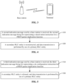
- the present state of the PDCP packet duplication function is the active state, and as shown in FIG. 4 , the data transmission method, based on the method shown in FIG. 1 , may further include the following steps 410 to 420.
- step 410 a second indication message sent by the base station is received, the second indication message being for representing a deactivation instruction for the PDCP packet duplication function.
- step 420 the secondary RLC entity is reconstructed, and data transmission is performed by use of the primary RLC entity.
- the secondary RLC entity may be reconstructed, and data transmission is performed by use of the primary RLC entity, so that successful data transmission can still be ensured when the PDCP packet duplication function is deactivated, and the reliability of data transmission can be improved.
- the data transmission method may further include the following steps 510 to 520.
- step 510 a third indication message sent by the base station is received, the third indication message being for representing a de-configuration instruction for the PDCP packet duplication function.
- step 520 the secondary RLC entity is released, and data transmission is performed by use of the primary RLC entity.
- the secondary RLC entity may be released as a default.
- the secondary RLC entity may be reconstructed, and data transmission is performed by use of the primary RLC entity, so that successful data transmission can still be ensured when the PDCP packet duplication function is deactivated, and the reliability of data transmission can be improved.
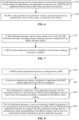
- the data transmission method may further include the following steps 610 to 620.
- step 610 a fourth indication message sent by the base station is received, the fourth indication message being for representing the de-configuration instruction for the PDCP packet duplication function and an RLC entity specified to be released.
- the RLC entity specified to be released may be one of the at least two transmission entities configured for the RB by the base station.
- the RLC entity specified to be released is one of the primary RLC entity and the secondary RLC entity.
- step 620 the RLC entity specified to be released is released, and data transmission is performed by use of an RLC entity not specified to be released.
- data transmission may be performed by use of the secondary RLC entity; and in a case that the RLC entity specified to be released is the secondary RLC entity, data transmission may be performed by use of the primary RLC entity.
- the RLC entity specified to be released may be released, and data transmission may be performed by use of a RLC entity not specified to be released, so that successful data transmission can still be ensured by use of the RLC entity not specified to be released when the PDCP packet duplication function is de-configured and the base station specifies the RLC entity to be released, and thus the reliability of data transmission can be improved.
- the data transmission method may further include the following steps 710 to 720.
- step 710 a fifth indication message sent by the base station is received, the fifth indication message being for representing a bearer splitting function configured for the RB by the base station.
- step 720 the PDCP packet duplication function is disabled, and the bearer splitting function is enabled.
- At least one of the following data transmission manners may be included, i.e., (5-1) or (5-2) or (5-3), wherein (5-2) is not according to the claimed invention.
- the PDCP packet duplication function may be disabled, the bearer splitting function may be enabled and the data that has been delivered to the RLC layer may be transmitted in more than one manner, so that successful data transmission can still be ensured even when different functions are switched, and the reliability of data transmission can be improved.
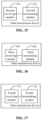
- FIG. 8 is a flowchart illustrating a data transmission method according to an exemplary embodiment, wherein not all of the features required by the claimed invention are shown.
- the data transmission method is applied to a base station. As shown in FIG. 8 , the data transmission method includes the following steps 810 to 840.
- a PDCP packet duplication function is configured for an RB.
- all transmission functions that can be implemented by the same RB are configured by the base station, and a terminal makes corresponding settings according to a configuration of the base station.
- step 820 at least two transmission entities configured to implement the PDCP packet duplication function are configured.
- the transmission entity refers to an RLC entity needed for implementation of the PDCP packet duplication function.
- a primary RLC entity and a secondary RLC entity are needed for implementation of the PDCP packet duplication function, and in such a case, the two RLC entities, i.e., the primary RLC entity and the secondary RLC entity, are configured for the RB.
- step 830 first information is added into a first indication message, the first information being for representing the PDCP packet duplication function and at least two transmission entities configured for the RB by the base station.
- the base station configures the PDCP packet duplication function, the primary RLC entity and the secondary RLC entity for the RB, configuration information of the base station is sent to a terminal through the first indication message.
- the first indication message is sent to a terminal to enable the terminal to set a transmission function corresponding to the RB to be the PDCP packet duplication function according to the first indication message and set a transmission entity corresponding to the RB according to the at least two transmission entities indicated in the first indication message.
- a PDCP packet duplication function is configured for an RB, at least two transmission entities configured to implement the PDCP packet duplication function are configured, first information is added into a first indication message, the first information being for representing the PDCP packet duplication function and the at least two transmission entities configured for the RB by the base station, so that the first indication message can be sent to the terminal to enable the terminal to set a transmission function corresponding to the RB to be the PDCP packet duplication function according to the first indication message and set a transmission entity corresponding to the RB according to the at least two transmission entities indicated in the first indication message, and then the terminal can set a transmission entity corresponding to the RB according to the at least two transmission entities indicated in the first indication message, set a present state of the PDCP packet duplication function, the present state including an active state and an inactive state, and perform data transmission according to the present state of the PDCP packet duplication function and the transmission entity corresponding to the RB, so that data transmission for the PDCP packet du
- the data transmission method may further include the following steps 910 to 920.
- step 910 an initial state of the PDCP packet duplication function is configured, the initial state being an active state or an inactive state.
- the base station configures an initial state of the PDCP packet duplication function for enabling the terminal to set a present state of the PDCP packet duplication function according to the initial state configured by the base station.
- step 920 second information for representing the initial state of the PDCP packet duplication function is added into the first indication message.
- the initial state of the PDCP packet duplication function may be configured, the initial state being an active state or an inactive state, to enable the terminal to set a present state of the PDCP packet duplication function according to a configuration of the base station and further perform data transmission according to the present state, and then the base station may flexibly determine whether to activate the PDCP packet duplication function or not, so that the base station can control the initial state of the PDCP packet duplication function and indirectly make a unified control over data transmission of the terminal, and the reliability of data transmission can be improved.
- the base station may instruct the terminal to deactivate the PDCP packet duplication function.
- the base station may send a second indication message to the terminal, the second indication message being for representing a deactivation instruction for the PDCP packet duplication function.
- the second indication message may be sent to the terminal, the second indication message being for representing a deactivation instruction for the PDCP packet duplication function, so that the base station can deactivate the PDCP packet duplication function, the controllability of data transmission can be improved, and the reliability of data transmission can be improved.
- the base station may instruct the terminal to de-configure the PDCP packet duplication function.
- the base station may send a third indication message to the terminal, the third indication message being for representing a de-configuration instruction for the PDCP packet duplication function.
- the third indication message may be sent to the terminal, the third indication message being for representing a de-configuration instruction for the PDCP packet duplication function, so that the base station can de-configure the PDCP packet duplication function, the controllability of data transmission can be improved, and the reliability of data transmission can be improved.
- the base station may further instruct the terminal to de-configure the PDCP packet duplication function and specify an RLC entity to be released.
- the base station may send a fourth indication message to the terminal, the fourth indication message being for representing a de-configuration instruction for the PDCP packet duplication function and an RLC entity specified to be released.
- the RLC entity specified to be released may be one of the at least two transmission entities configured for the RB by the base station.
- the RLC entity specified to be released may be one of the primary RLC entity and the secondary RLC entity.
- the fourth indication message may be sent to the terminal, the fourth indication message being for representing a de-configuration instruction for the PDCP packet duplication function and representing an RLC entity specified to be released, so that the base station can de-configure the PDCP packet duplication function and also implement control over the RLC entity, furthermore, the data transmission can be controlled better, and the reliability of data transmission can be improved.
- the base station may instruct the terminal to configure a bearer splitting function.
- the base station may send a fifth indication message to the terminal, the fifth indication message being for representing a bearer splitting function configured for the RB by the base station.
- the fifth indication message may be sent to the terminal, the fifth indication message being for representing a bearer splitting function configured for the RB by the base station, so that handover between the PDCP packet duplication function and the bearer splitting function can be implemented, one or more transmission functions can further be realized for the same RB by use of at least two shared transmission entities, transmission functions of the RB can be enriched, and the practicability of data transmission can be improved.
- the present disclosure also provides embodiments of a data transmission device.
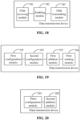
- FIG. 10 is a block diagram of a data transmission device, which in the shown form with several modules is not according to the claimed invention.
- the data transmission device may be applied to a terminal, and is configured to execute the data transmission method shown in FIG. 1 .
- the data transmission device may include:
- the terminal may receive a first indication message from the base station, the first indication message including first information and the first information being for representing a PDCP packet duplication function and at least two transmission entities configured for the RB by the base station, set a transmission function corresponding to an RB to be the PDCP packet duplication function according to the first indication message, set a transmission entity corresponding to the RB according to the at least two transmission entities indicated in the first indication message, set a present state of the PDCP packet duplication function, the present state including an active state and an inactive state, and perform data transmission according to the present state of the PDCP packet duplication function and the transmission entity corresponding to the RB, so that data transmission for the PDCP packet duplication function is implemented, and the reliability of data transmission can be improved.
- the at least two transmission entities configured by the base station include a primary RLC entity and a secondary RLC entity
- the second setting module 103 may include:
- the terminal may further set a primary RLC entity and a secondary RLC entity corresponding to the RB according to the primary RLC entity and secondary RLC entity configured for the RB by the base station to satisfy the two transmission entities needed for implementation of the PDCP packet duplication function and may transmit a PDCP packet and a PDCP packet duplicate through the two transmission entities, so that the speed of data transmission can be increased, the reliability of data transmission can be improved, and a low sending success rate can be upgraded when the PDCP packet and the PDCP packet duplicate are transmitted on the same transmission entity.
- the third setting module 104 may include:
- the present state of the PDCP packet duplication function may be set according to a configuration of the base station, and in a case that there is no configuration of the base station, the present state of the PDCP packet duplication function may also be set according to the system default initial state, so that subsequent data transmission according to the present state can be ensured, and diversity of data transmission can be improved.
- the present state of the PDCP packet duplication function is the inactive state
- the transmission entity corresponding to the RB includes the primary RLC entity and the secondary RLC entity
- the first transmitting module 105 may include:
- whether the RB is a newly established SRB or DRB or is an SRB or DRB that has been established may be required to be distinguished for data transmission, and particularly for the SRB or DRB that has been established, whether data transmission is for the data that is not delivered to the RLC layer or the data that has been delivered to the secondary RLC entity may be further required to be distinguished, so that different processing is implemented for data that is not sent and data that has been sent, and the reliability of data transmission can be improved.
- the second transmission submodule 132 may further include: a third transmission submodule, configured to, when data transmission may be performed by use of the primary RLC entity for the data that is not delivered to the RLC layer and the data that has been delivered to the secondary RLC entity but has not yet been successfully sent, reconstruct the secondary RLC entity that has been constructed.
- a third transmission submodule configured to, when data transmission may be performed by use of the primary RLC entity for the data that is not delivered to the RLC layer and the data that has been delivered to the secondary RLC entity but has not yet been successfully sent, reconstruct the secondary RLC entity that has been constructed.
- the secondary RLC entity that has been constructed may be reconstructed, namely, data in the secondary RLC entity that has been constructed is deleted, to prepare for subsequent data transmission, so that the reliability of data transmission can be improved.
- the present state of the PDCP packet duplication function is the inactive state
- the transmission entity corresponding to the RB includes the primary RLC entity and the secondary RLC entity
- the first transmitting module 105 may include: a fourth transmission submodule 141, configured to adopt at least one of the following data transmission manners:
- the two transmission entities i.e., the primary RLC entity and the secondary RLC entity
- the PDCP packet and the PDCP packet duplicate may be sent through the primary RLC entity and the secondary RLC entity respectively, or different transmission manners in the AM or the UM may be adopted, so that the data that is not sent and has been sent may be transmitted in multiple transmission manners, the reliability of data transmission can be ensured, and meanwhile, the efficiency of data transmission can be improved.
- the present state of the PDCP packet duplication function is the inactive state
- the device may further include:
- the secondary RLC entity may be reconstructed, and data transmission may be performed by use of the primary RLC entity, so that successful data transmission can still be ensured when the PDCP packet duplication function is deactivated, and the reliability of data transmission can be improved.
- the device may further include:
- the secondary RLC entity may further be released, and data transmission may be performed by use of the primary RLC entity, so that successful data transmission can still be ensured when the PDCP packet duplication function is de-configured, and the reliability of data transmission can be improved.
- the device may further include:
- the RLC entity specified to be released may be released, and data transmission may be performed by use of an RLC entity not specified to be released, so that successful data transmission can still be ensured by use of the RLC entity not specified to be released in a case that the PDCP packet duplication function is de-configured and the base station specifies the RLC entity to be released, and the reliability of data transmission can be improved.
- the device may further include:
- the PDCP packet duplication function may be disabled, the bearer splitting function may be enabled and the data that has been delivered to the RLC layer may be transmitted in more than one manner, so that successful data transmission can still be ensured even when handover between different functions is performed, and the reliability of data transmission can be improved.
- FIG. 19 is a block diagram of a data transmission device according to an exemplary embodiment in the shown form not covered by the claimed invention.
- the data transmission device may be applied to a base station, and is configured to execute the data transmission method shown in FIG. 8 .
- the data transmission device may include:
- a PDCP packet duplication function is configured for an RB, at least two transmission entities configured to implement a PDCP packet duplication function are configured, first information is added into first indication message, the first information being for representing the PDCP packet duplication function and at least two transmission entities configured for the RB by the base station, and the first indication message is sent to the terminal, therefore, the terminal can set a transmission function corresponding to the RB to be the PDCP packet duplication function according to the first indication message and set a transmission entity corresponding to the RB according to the at least two transmission entities indicated in the first indication message, and then the terminal can set the transmission entity corresponding to the RB according to the at least two transmission entities indicated in the first indication message, set a present state of the PDCP packet duplication function, the present state including an active state and an inactive state, and can perform data transmission according to the present state of the PDCP packet duplication function and the transmission entity corresponding to the RB, so that data transmission for the PDCP packet duplication function is
- the device may further include:
- an initial state of a PDCP packet duplication function is configured, the initial state being an active state or an inactive state, therefore, the terminal can set a present state of the PDCP packet duplication function according to a configuration of the base station and further can perform data transmission according to the present state, and then the base station can flexibly determine whether to activate the PDCP packet duplication function or not, so that the base station can control the initial state of the PDCP packet duplication function and can indirectly make a unified control over data transmission of the terminal, and the reliability of data transmission can be improved.
- the device may further include: a second sending module, configured to send a second indication message to the terminal, the second indication message being for representing a deactivation instruction for the PDCP packet duplication function.
- the second indication message is sent to the terminal, the second indication message being for representing a deactivation instruction for the PDCP packet duplication function, so that the base station can deactivate the PDCP packet duplication function, the controllability of data transmission can be improved, and the reliability of data transmission can be improved.
- the device may further include: a third sending module, configured to send a third indication message to the terminal, the third indication message being for representing a de-configuration instruction for the PDCP packet duplication function.
- the third indication message is sent to the terminal, the third indication message being for representing the de-configuration instruction for the PDCP packet duplication function, so that the base station can de-configure the PDCP packet duplication function, the controllability of data transmission can be improved, and the reliability of data transmission can be improved.
- the device may further include: a fourth sending module, configured to send a fourth indication message to the terminal, the fourth indication message being for representing a de-configuration instruction for the PDCP packet duplication function and representing an RLC entity specified to be released.
- a fourth sending module configured to send a fourth indication message to the terminal, the fourth indication message being for representing a de-configuration instruction for the PDCP packet duplication function and representing an RLC entity specified to be released.
- the fourth indication message is sent to the terminal, the fourth indication message being for representing a de-configuration instruction for the PDCP packet duplication function and representing an RLC entity specified to be released, so that the base station can de-configure the PDCP packet duplication function and also implement control over the RLC entity, the controllability of data transmission can further be improved, and the reliability of data transmission can be improved.
- the device may further include: a fifth sending module, configured to send a fifth indication message to the terminal, the fifth indication message being for representing a bearer splitting function configured for the RB by the base station.
- the fifth indication message is sent to the terminal, the fifth indication message being for representing a bearer splitting function configured for the RB by the base station, so that handover between the PDCP packet duplication function and the bearer splitting function can be implemented, one or more transmission functions can further be realized for the same RB by use of at least two shared transmission entities, transmission functions of the RB can be enriched, and practicability of data transmission can be improved.
- the device embodiments substantially correspond to the method embodiments, and thus related parts refer to part of descriptions of the method embodiments.
- the device embodiments described above are only schematic, units described as separate parts therein may or may be not physically separated, and parts displayed as units may or may be not physical units, and namely may be located in the same place or may be distributed to multiple network units. Part or all of the modules therein may be selected according to a practical requirement to achieve the solutions of the present disclosure. Those of ordinary skill in the art may understand and implement without creative work.
- the present disclosure also provides a non-transitory computer-readable storage medium is provided, which has a computer program stored thereon, the computer program being configured to execute any data transmission method shown in FIG. 1 to FIG. 7 .
- the present disclosure also provides a non-transitory computer-readable storage medium is provided, which has a computer program stored thereon, the computer program being configured to execute any data transmission method shown in FIG. 8 to FIG. 9 .
- the present disclosure also provides a data transmission device, which is applied to a terminal and includes:
- FIG. 21 is a structure diagram of a data transmission device according to an exemplary embodiment.
- FIG. 21 illustrates a data transmission device 2100 according to an exemplary embodiment.
- the data transmission device 2100 may be a terminal such as a computer, a mobile phone, a digital broadcast terminal, a messaging device, a gaming console, a tablet, a medical device, exercise equipment and a personal digital assistant.
- the data transmission device 2100 may include one or more of the following components: a processing component 2101, a memory 2102, a power component 2103, a multimedia component 2104, an audio component 2105, an Input/Output (I/O) interface 2106, a sensor component 2107, and a communication component 2108.
- the processing component 2101 is typically configured to control overall operations of the data transmission device 2100, such as the operations associated with display, telephone calls, data communications, camera operations, and recording operations.
- the processing component 2101 may include one or more processors 2109, as required by the claimed invention, to execute instructions to perform all or part of the steps in the abovementioned method.
- the processing component 2101 may include one or more modules which facilitate interaction between the processing component 2101 and other components.
- the processing component 2101 may include a multimedia module to facilitate interaction between the multimedia component 2104 and the processing component 2101.
- the memory 2102 is configured to store various types of data to support the operation of the data transmission device 2100. Examples of such data may include instructions for any application programs or methods operated on the data transmission device 2100, contact data, phonebook data, messages, pictures, video, etc.
- the memory 2102 may be implemented by any type of volatile or non-volatile memory devices, or a combination thereof, such as a Static Random Access Memory (SRAM), an Electrically Erasable Programmable Read-Only Memory (EEPROM), an Erasable Programmable Read-Only Memory (EPROM), a Programmable Read-Only Memory (PROM), a Read-Only Memory (ROM), a magnetic memory, a flash memory, and a magnetic or optical disk.
- SRAM Static Random Access Memory
- EEPROM Electrically Erasable Programmable Read-Only Memory
- EPROM Erasable Programmable Read-Only Memory
- PROM Programmable Read-Only Memory
- ROM Read-Only Memory
- magnetic memory a magnetic memory
- flash memory and
- the power component 2103 is configured to provide power for various components of the data transmission device 2100.
- the power component 2103 may include a power management system, one or more power supplies, and other components associated with generation, management and distribution of power for the data transmission device 2100.
- the multimedia component 2104 may include a screen for providing an output interface between the data transmission device 2100 and a user.
- the screen may include a Liquid Crystal Display (LCD) and a Touch Panel (TP). If the screen includes the TP, the screen may be implemented as a touch screen to receive an input signal from the user.
- the TP may include one or more touch sensors to sense touches, swipes and gestures on the TP. The touch sensors may not only sense a boundary of a touch or swipe action but also detect a duration and pressure associated with the touch or swipe action.
- the multimedia component 2104 may include a front camera and/or a rear camera.
- the front camera and/or the rear camera may receive external multimedia data when the data transmission device 2100 is in an operation mode, such as a photographing mode or a video mode.
- an operation mode such as a photographing mode or a video mode.
- Each of the front camera and the rear camera may be a fixed optical lens system or have focusing and optical zooming capabilities.
- the audio component 2105 is configured to output and/or input an audio signal.
- the audio component 2105 may include a Microphone (MIC), and the MIC is configured to receive an external audio signal when the data transmission device 2100 is in the operation mode, such as a call mode, a recording mode and a voice recognition mode.
- the received audio signal may further be stored in the memory 2102 or sent through the communication component 2108.
- the audio component 2105 may further include a speaker configured to output the audio signal.
- the I/O interface 2106 is configured to provide an interface between the processing component 2101 and a peripheral interface module, and the peripheral interface module may be a keyboard, a click wheel, a button and the like.
- the button may include, but not limited to: a home button, a volume button, a starting button and a locking button.
- the sensor component 2107 may include one or more sensors configured to provide status assessment in various aspects for the data transmission device 2100. For instance, the sensor component 2107 may detect an on/off status of the data transmission device 2100 and relative positioning of components, such as a display and small keyboard of the data transmission device 2100, and the sensor component 2107 may further detect a change in a position of the data transmission device 2100 or a component of the data transmission device 2100, presence or absence of contact between the user and the data transmission device 2100, orientation or acceleration/deceleration of the data transmission device 2100 and a change in temperature of the data transmission device 2100.
- the sensor component 2107 may include a proximity sensor configured to detect presence of an object nearby without any physical contact.
- the sensor component 2107 may also include a light sensor, such as a Complementary Metal Oxide Semiconductor (CMOS) or Charge Coupled Device (CCD) image sensor, configured for use in an imaging application.
- CMOS Complementary Metal Oxide Semiconductor
- CCD Charge Coupled Device
- the sensor component 2107 may also include an acceleration sensor, a gyroscope sensor, a magnetic sensor, a pressure sensor or a temperature sensor.
- the communication component 2108 is configured to facilitate wired or wireless communication between the data transmission device 2100 and another device.
- the data transmission device 2100 may access a communication-standard-based wireless network, such as a Wireless Fidelity (WiFi) network, a 2nd-Generation (2G) or 3rd-Generation (3G) network or a combination thereof.
- WiFi Wireless Fidelity
- 2G 2nd-Generation
- 3G 3rd-Generation
- the communication component 2108 may receive a broadcast signal or broadcast associated information from an external broadcast management system through a broadcast channel.
- the communication component 2108 may further include a Near Field Communication (NFC) module to facilitate short-range communication.
- NFC Near Field Communication
- the NFC module may be implemented based on a Radio Frequency Identification (RFID) technology, an Infrared Data Association (IrDA) technology, an Ultra-WideBand (UWB) technology, a Bluetooth (BT) technology and another technology.
- RFID Radio Frequency Identification
- IrDA Infrared Data Association
- UWB Ultra-WideBand
- BT Bluetooth
- the data transmission device 2100 may be implemented by one or more Application Specific Integrated Circuits (ASICs), Digital Signal Processors (DSPs), Digital Signal Processing Devices (DSPDs), Programmable Logic Devices (PLDs), Field Programmable Gate Arrays (FPGAs), controllers, micro-controllers, microprocessors or other electronic components, and is configured to execute the abovementioned method.
- ASICs Application Specific Integrated Circuits
- DSPs Digital Signal Processors
- DSPDs Digital Signal Processing Devices
- PLDs Programmable Logic Devices
- FPGAs Field Programmable Gate Arrays
- controllers micro-controllers, microprocessors or other electronic components, and is configured to execute the abovementioned method.
- non-transitory computer-readable storage medium including instructions, such as the memory 2102 including instructions, and the instructions may be executed by the processor 2109 of the data transmission device 2100 to implement the abovementioned method.
- the non-transitory computer-readable storage medium may be a ROM, a Random Access Memory (RAM), a Compact Disc Read-Only Memory (CD-ROM), a magnetic tape, a floppy disc, an optical data storage device and the like.
- the instructions in the storage medium may be executed by the processor to enable the data transmission device 2100 to execute any data transmission method.
- the present disclosure also provides a data transmission device, which is applied to a base station and includes:
- FIG. 22 is a structure diagram of a data transmission device according to an exemplary embodiment in the shown form not according to the claimed invention.
- the data transmission device 2200 may be provided as a base station.
- the data transmission device 2200 includes a processing component 2222, a wireless transmission/receiving component 2224, an antenna component 2226 and a wireless interface-specific signal processing part, and the processing component 2222 may further include one or more processors.
- One processor in the processing component 2222 may be configured to execute any data transmission method.
Claims (11)
- Un procédé de transmission de données, mis en oeuvre par un terminal, le procédé comprenant :la réception (110) d'un premier message d'indication d'une station de base, dans lequel le premier message d'indication comprend des premières informations et les premières informations sont destinées à représenter une fonction de duplication de paquets de protocole de convergence de données par paquets, PDCP et au moins deux entités de transmission configurées pour une porteuse radio, RB, par la station de base, dans lequel les au moins deux entités de transmission comprennent une entité de commande de liaison radio, RLC, primaire et une entité RLC secondaire ;la définition (120) d'une fonction de transmission correspondant à la RB comme étant la fonction de duplication de paquets PDCP selon le premier message d'indication ;la définition (130) d'au moins deux entités de transmission correspondant à la RB selon les au moins deux entités de transmission indiquées dans le premier message d'indication ;la définition (140) d'un état actuel de la fonction de duplication de paquets PDCP, l'état actuel comprenant un état actif et un état inactif ; etla réalisation (150) d'une transmission de données selon l'état actuel et l'entité de transmission,caractérisé en ce que,l'état actuel de la fonction de duplication de paquets PDCP est l'état inactif,la réalisation de la transmission de données selon l'état actuel et l'entité de transmission comprend :dans un cas où la RB est une porteuse radio de signalisation, SRB, nouvellement établie ou une porteuse radio de données, DRB, la réalisation de la transmission de données en utilisant l'entité RLC primaire ; etdans un cas où la RB est une SRB ou DRB qui a été établie, l'adoption d'au moins l'une des modalités de transmission de données suivantes :la réalisation de la transmission de données en utilisant l'entité RLC primaire pour des données qui ne sont pas fournies à une couche RLC et la poursuite de la transmission de données en utilisant l'entité RLC secondaire pour des données qui ont été fournies à l'entité RLC secondaire, oudans un mode sans accusé de réception, UM, la réalisation de la transmission de données en utilisant l'entité RLC primaire pour des données qui ne sont pas fournies à la couche RLC.
- Le procédé selon la revendication 1, dans lequel la définition des au moins deux entités de transmission correspondant à la RB selon les au moins deux entités de transmission indiquées dans le premier message d'indication comprend :dans le cas où la RB est la SRB ou DRB nouvellement établie, la construction d'une première entité RLC et d'une seconde entité RLC, la définition de la première entité RLC comme étant l'entité RLC primaire et la définition de la seconde entité RLC comme étant l'entité RLC secondaire ; etdans le cas où la RB est la SRB ou DRB qui a été établie, la définition d'une entité RLC qui a été construite comme étant l'entité RLC primaire, et la définition d'une autre entité RLC qui a été construite comme étant l'entité RLC secondaire.
- Le procédé selon la revendication 1, dans lequel la définition de l'état actuel de la fonction de duplication de paquets PDCP adopte au moins l'une des modalités de définition suivantes :la définition de l'état actuel comme étant un état initial par défaut du système, l'état initial par défaut du système comprenant l'état actif ou l'état inactif ; oudans un cas où le premier message d'indication comprend en outre des secondes informations, les secondes informations sont destinées à représenter un état initial, configuré par la station de base, de la fonction de duplication de paquets PDCP et l'état initial est l'état inactif, la définition de l'état actuel comme étant l'état initial, configuré par la station de base, de la fonction de duplication de paquets PDCP selon les secondes informations.
- Le procédé selon la revendication 1, comprenant en outre :la réception d'un troisième message d'indication de la station de base, le troisième message d'indication étant destiné à représenter une instruction de déconfiguration pour la fonction de duplication de paquets PDCP ; etla libération de l'entité RLC secondaire, et la réalisation de la transmission de données en utilisant l'entité RLC primaire.
- Le procédé selon la revendication 1, comprenant en outre :la réception d'un quatrième message d'indication de la station de base, le quatrième message d'indication étant destiné à représenter une instruction de déconfiguration pour la fonction de duplication de paquets PDCP et à représenter une entité RLC spécifiée comme étant à libérer ; etla libération de l'entité RLC spécifiée comme étant à libérer, et la réalisation de la transmission de données en utilisant une entité RLC non spécifiée comme étant à libérer.
- Le procédé selon la revendication 1, comprenant en outre :la réception d'un cinquième message d'indication de la station de base, le cinquième message d'indication étant destiné à représenter une fonction de division de porteuse configurée pour la RB par la station de base ; à désactiver la fonction de duplication de paquets PDCP et à activer la fonction de division de porteuse ; etl'adoption d'au moins l'une des modalités de transmission de données suivantes pour des données qui ont été fournies à une couche RLC :la poursuite de la transmission de données en utilisant l'entité RLC primaire et l'entité RLC secondaire, oudans un cas où l'état actuel de la fonction de duplication de paquets PDCP est l'état inactif avant que la fonction de duplication de paquets PDCP ne soit désactivée, la poursuite de la transmission de données en utilisant l'entité RLC primaire et l'entité RLC secondaire.
- Un procédé de transmission de données, mis en oeuvre par une station de base, le procédé comprenant :la configuration (810) d'une fonction de duplication de paquets de protocole de convergence de données par paquets, PDCP, pour une porteuse radio, RB ;la configuration (820) d'au moins deux entités de transmission configurées pour mettre en oeuvre la fonction de duplication de paquets PDCP, dans lequel les au moins deux entités de transmission comprennent une entité de commande de liaison radio, RLC, primaire et une entité RLC secondaire ;l'ajout (830) de premières informations dans un premier message d'indication, les premières informations étant destinées à représenter la fonction de duplication de paquets PDCP et les au moins deux entités de transmission ; etl'envoi (840) du premier message d'indication à un terminal pour permettre au terminal de définir une fonction de transmission correspondant à la RB comme étant la fonction de duplication de paquets PDCP selon le premier message d'indication et de définir au moins deux entités de transmission correspondant à la RB selon les au moins deux entités de transmission indiquées dans le premier message d'indication,caractérisé en ce que,un état actuel de la fonction de duplication de paquets PDCP est un état inactif ;dans un cas où la RB est une porteuse radio de signalisation, SRB, nouvellement établie ou une porteuse radio de données, DRB, la transmission de données est réalisée en utilisant l'entité RLC primaire ; etdans un cas où la RB est une SRB ou une DRB qui a été établie, la transmission de données est réalisée par au moins l'une des modalités suivantes :la réalisation de la transmission de données en utilisant l'entité RLC primaire pour des données qui ne sont pas fournies à une couche RLC et la poursuite de la transmission de données en utilisant l'entité RLC secondaire pour des données qui ont été fournies à l'entité RLC secondaire, oudans un mode sans accusé de réception, UM, la réalisation de la transmission de données en utilisant l'entité RLC primaire pour des données qui ne sont pas fournies à la couche RLC.
- Le procédé selon la revendication 7, comprenant en outre :la configuration d'un état initial de la fonction de duplication de paquets PDCP, l'état initial étant un état actif ou l'état inactif ; etl'ajout de secondes informations pour représenter l'état initial dans le premier message d'indication.
- Le procédé selon la revendication 7, comprenant en outre :l'envoi d'un deuxième message d'indication au terminal, le deuxième message d'indication étant destiné à représenter une instruction de désactivation pour la fonction de duplication de paquets PDCP ; oul'envoi d'un troisième message d'indication au terminal, le troisième message d'indication étant destiné à représenter une instruction de déconfiguration pour la fonction de duplication de paquets PDCP ; oul'envoi d'un quatrième message d'indication au terminal, le quatrième message d'indication étant destiné à représenter une instruction de déconfiguration pour la fonction de duplication de paquets PDCP et une entité RLC spécifiée comme étant à libérer ; oul'envoi d'un cinquième message d'indication au terminal, le cinquième message d'indication étant destiné à représenter une fonction de division de porteuse configurée pour la RB par la station de base.
- Un dispositif de transmission de données, mis en oeuvre par un terminal, le dispositif comprenant :un processeur ; etune mémoire configurée pour stocker une instruction exécutable pour le processeur,dans lequel le processeur est configuré pour mettre en oeuvre les étapes du procédé selon l'une quelconque des revendications 1-6.
- Un dispositif de transmission de données, mis en oeuvre par une station de base, le dispositif comprenant :un processeur ; etune mémoire configurée pour stocker une instruction exécutable pour le processeur,dans lequel le processeur est configuré pour mettre en oeuvre les étapes du procédé selon l'une quelconque des revendications 7-9.
Applications Claiming Priority (1)
| Application Number | Priority Date | Filing Date | Title |
|---|---|---|---|
| PCT/CN2017/098352 WO2019036862A1 (fr) | 2017-08-21 | 2017-08-21 | Procédé et dispositif de transmission de données |
Publications (3)
| Publication Number | Publication Date |
|---|---|
| EP3668253A1 EP3668253A1 (fr) | 2020-06-17 |
| EP3668253A4 EP3668253A4 (fr) | 2020-07-22 |
| EP3668253B1 true EP3668253B1 (fr) | 2023-07-12 |
Family
ID=63095032
Family Applications (1)
| Application Number | Title | Priority Date | Filing Date |
|---|---|---|---|
| EP17922883.8A Active EP3668253B1 (fr) | 2017-08-21 | 2017-08-21 | Procédés et dispositifs de transmission de données |
Country Status (11)
| Country | Link |
|---|---|
| US (2) | US11240874B2 (fr) |
| EP (1) | EP3668253B1 (fr) |
| JP (1) | JP7004472B2 (fr) |
| KR (1) | KR102340554B1 (fr) |
| CN (1) | CN108401484B (fr) |
| BR (1) | BR112020003446A2 (fr) |
| ES (1) | ES2958666T3 (fr) |
| PL (1) | PL3668253T3 (fr) |
| RU (1) | RU2746271C1 (fr) |
| SG (1) | SG11202001289VA (fr) |
| WO (1) | WO2019036862A1 (fr) |
Families Citing this family (32)
| Publication number | Priority date | Publication date | Assignee | Title |
|---|---|---|---|---|
| JP2021514562A (ja) * | 2017-12-27 | 2021-06-10 | オッポ広東移動通信有限公司Guangdong Oppo Mobile Telecommunications Corp., Ltd. | Srb伝送方法及び装置 |
| CN110139397B (zh) * | 2018-02-09 | 2021-04-06 | 电信科学技术研究院有限公司 | 一种分组数据汇聚协议pdcp重复机制的激活方法及节点设备 |
| KR102614875B1 (ko) * | 2018-03-03 | 2023-12-19 | 광동 오포 모바일 텔레커뮤니케이션즈 코포레이션 리미티드 | 사용자 디바이스 및 무선 통신 시스템에서 사용자 디바이스의 전송을 제어하기 위한 방법 |
| US11153792B2 (en) * | 2018-04-18 | 2021-10-19 | Qualcomm Incorporated | Signaling for inactive mobility |
| CN110958709A (zh) * | 2018-09-27 | 2020-04-03 | 维沃移动通信有限公司 | 数据传输方法及通信设备 |
| CN110972335B (zh) * | 2018-09-29 | 2022-04-12 | 华为技术有限公司 | 一种模式切换方法、数据流分流方法及装置 |
| CN111107581B (zh) * | 2018-10-26 | 2020-10-02 | 展讯通信(上海)有限公司 | Pdcp复制功能的确定、指示方法及装置、基站、终端 |
| CN112585900A (zh) | 2018-10-30 | 2021-03-30 | Oppo广东移动通信有限公司 | 一种数据处理方法、终端设备及存储介质 |
| CN113543213B (zh) * | 2018-10-30 | 2023-05-26 | Oppo广东移动通信有限公司 | 基于复制数据的传输方法和设备 |
| WO2020090072A1 (fr) * | 2018-10-31 | 2020-05-07 | 株式会社Nttドコモ | Équipement d'utilisateur et appareil de station de base |
| CN111132375B (zh) * | 2018-10-31 | 2021-09-10 | 维沃移动通信有限公司 | 一种分离承载的控制方法及相关设备 |
| EP3874636A1 (fr) * | 2018-11-01 | 2021-09-08 | Nokia Technologies Oy | Appareil, procédé et programme informatique |
| WO2020118519A1 (fr) * | 2018-12-11 | 2020-06-18 | Oppo广东移动通信有限公司 | Procédé de communication sans fil, dispositif terminal et dispositif réseau |
| WO2020118991A1 (fr) * | 2018-12-11 | 2020-06-18 | Oppo广东移动通信有限公司 | Procédé de communication sans fil, dispositif terminal et dispositif de réseau |
| CN111404633B (zh) * | 2019-01-03 | 2021-10-26 | 华为技术有限公司 | 一种选择传输模式的方法及设备 |
| CA3122886A1 (fr) * | 2019-01-14 | 2020-07-23 | Guangdong Oppo Mobile Telecommunications Corp., Ltd. | Procede et dispositif de traitement de flux de donnees, et support d'informations |
| WO2020147051A1 (fr) * | 2019-01-16 | 2020-07-23 | Oppo广东移动通信有限公司 | Procédé de transmission de données et dispositif terminal |
| EP3913837B1 (fr) * | 2019-01-16 | 2023-05-24 | Guangdong Oppo Mobile Telecommunications Corp., Ltd. | Procédé de transmission de données, et dispositif de communication |
| CN111278061B (zh) * | 2019-01-18 | 2021-09-07 | 维沃移动通信有限公司 | 数据处理方法、信息配置方法、终端及网络设备 |
| CN113424580B (zh) * | 2019-02-03 | 2024-04-05 | 鸿颖创新有限公司 | 用于演进分组数据汇聚协议复制的方法及装置 |
| US20220132557A1 (en) * | 2019-02-14 | 2022-04-28 | Nokia Technologies Oy | Apparatus, Method and Computer Program for Communication Using Configured Grants |
| CN111436066A (zh) * | 2019-02-14 | 2020-07-21 | 维沃移动通信有限公司 | 数据包承载路径确定、信息发送方法和设备 |
| CN111698731B (zh) * | 2019-03-14 | 2023-01-10 | 中国移动通信有限公司研究院 | 协议实体建立、数据缓存方法及其装置、设备、存储介质 |
| CN111465119B (zh) * | 2019-03-28 | 2023-02-24 | 维沃移动通信有限公司 | 数据发送方法、信息配置方法、终端及网络设备 |
| CN111757548B (zh) * | 2019-03-29 | 2022-05-24 | 华为技术有限公司 | 通信方法和通信装置 |
| WO2020199181A1 (fr) * | 2019-04-04 | 2020-10-08 | Qualcomm Incorporated | Message de commande pour sélection d'entité de commande de liaison radio (rlc) dynamique |
| CN114080828A (zh) * | 2019-06-25 | 2022-02-22 | 苹果公司 | 用于蜂窝语音的ue辅助信息 |
| WO2021016778A1 (fr) * | 2019-07-26 | 2021-02-04 | Oppo广东移动通信有限公司 | Procédé de sélection de ressources de transmission, appareil de réseau, et équipement d'utilisateur |
| WO2021016790A1 (fr) * | 2019-07-29 | 2021-02-04 | Oppo广东移动通信有限公司 | Procédé de communication radio, dispositif terminal et dispositif de réseau |
| JP2023520304A (ja) * | 2020-04-09 | 2023-05-17 | オッポ広東移動通信有限公司 | データ伝送方法、送信機器及び記憶媒体 |
| CN116325895A (zh) * | 2020-04-10 | 2023-06-23 | Oppo广东移动通信有限公司 | 数据传输方法及相关设备 |
| CN115696642A (zh) * | 2021-07-23 | 2023-02-03 | 夏普株式会社 | 由用户设备ue执行的方法及用户设备 |
Citations (1)
| Publication number | Priority date | Publication date | Assignee | Title |
|---|---|---|---|---|
| EP3641192A1 (fr) * | 2017-06-15 | 2020-04-22 | Huawei Technologies Co., Ltd. | Procédé de traitement de communication et appareil de communication |
Family Cites Families (17)
| Publication number | Priority date | Publication date | Assignee | Title |
|---|---|---|---|---|
| US8830950B2 (en) * | 2007-06-18 | 2014-09-09 | Qualcomm Incorporated | Method and apparatus for PDCP reordering at handoff |
| KR102257628B1 (ko) * | 2013-10-21 | 2021-05-28 | 엘지전자 주식회사 | 이중 연결성에서의 상향링크 데이터 전송 방법 및 이를 위한 장치 |
| EP3095289B1 (fr) * | 2014-01-17 | 2020-04-15 | Samsung Electronics Co., Ltd. | Procédé et système de gestion de sélection de cellule secondaire spéciale en connectivité double |
| JP5852193B1 (ja) * | 2014-08-06 | 2016-02-03 | 株式会社Nttドコモ | ユーザ装置 |
| US10142799B2 (en) * | 2014-08-19 | 2018-11-27 | Qualcomm Incorporated | Multicasting traffic using multi-connectivity |
| KR20190098754A (ko) * | 2017-01-13 | 2019-08-22 | 삼성전자주식회사 | 무선 통신 시스템에서 데이터 패킷을 전송하는 방법 및 장치 |
| WO2018143600A1 (fr) | 2017-02-02 | 2018-08-09 | Lg Electronics Inc. | Procédé et dispositif de transmission d'unité de données |
| ES2962322T3 (es) * | 2017-03-24 | 2024-03-18 | Nokia Technologies Oy | Gestión de duplicación de pdcp y recuperación de datos en una nueva tecnología de acceso por radio |
| KR102625204B1 (ko) * | 2017-04-24 | 2024-01-16 | 모토로라 모빌리티 엘엘씨 | 무선 베어러에 대한 pdcp pdu들의 복제 |
| US10805836B2 (en) * | 2017-05-05 | 2020-10-13 | Qualcomm Incorporated | Packet duplication at a packet data convergence protocol (PDCP) entity |
| US11363569B2 (en) * | 2017-06-15 | 2022-06-14 | Samsung Electronics Co., Ltd. | Logical channel mapping with packet duplication |
| EP3582429B1 (fr) * | 2017-06-15 | 2021-08-04 | Samsung Electronics Co., Ltd. | Commande de duplication de paquet |
| CN109150432A (zh) * | 2017-06-15 | 2019-01-04 | 夏普株式会社 | 无线通信方法和设备 |
| EP3642993A4 (fr) * | 2017-06-22 | 2021-03-24 | FG Innovation Company Limited | Systèmes, dispositifs et procédés de duplication d'unité de données par paquets de protocole de convergence de données par paquets |
| SG11201911628TA (en) * | 2017-07-28 | 2020-01-30 | Guangdong Oppo Mobile Telecommunications Corp Ltd | Data transmission method and related product |
| US10798775B2 (en) * | 2017-08-10 | 2020-10-06 | Qualcomm Incorporated | Techniques and apparatuses for duplication bearer management |
| KR102315038B1 (ko) * | 2017-08-21 | 2021-10-22 | 베이징 시아오미 모바일 소프트웨어 컴퍼니 리미티드 | 무선 베어러의 지시 방법 및 장치 |
-
2017
- 2017-08-21 ES ES17922883T patent/ES2958666T3/es active Active
- 2017-08-21 CN CN201780001444.9A patent/CN108401484B/zh active Active
- 2017-08-21 EP EP17922883.8A patent/EP3668253B1/fr active Active
- 2017-08-21 KR KR1020207007059A patent/KR102340554B1/ko active IP Right Grant
- 2017-08-21 RU RU2020109837A patent/RU2746271C1/ru active
- 2017-08-21 SG SG11202001289VA patent/SG11202001289VA/en unknown
- 2017-08-21 PL PL17922883.8T patent/PL3668253T3/pl unknown
- 2017-08-21 BR BR112020003446-0A patent/BR112020003446A2/pt unknown
- 2017-08-21 JP JP2020509426A patent/JP7004472B2/ja active Active
- 2017-08-21 WO PCT/CN2017/098352 patent/WO2019036862A1/fr unknown
-
2020
- 2020-02-19 US US16/794,778 patent/US11240874B2/en active Active
-
2021
- 2021-12-21 US US17/557,520 patent/US11659620B2/en active Active
Patent Citations (1)
| Publication number | Priority date | Publication date | Assignee | Title |
|---|---|---|---|---|
| EP3641192A1 (fr) * | 2017-06-15 | 2020-04-22 | Huawei Technologies Co., Ltd. | Procédé de traitement de communication et appareil de communication |
Also Published As
| Publication number | Publication date |
|---|---|
| CN108401484A (zh) | 2018-08-14 |
| EP3668253A4 (fr) | 2020-07-22 |
| JP7004472B2 (ja) | 2022-01-21 |
| CN108401484B (zh) | 2023-02-17 |
| US20200187297A1 (en) | 2020-06-11 |
| WO2019036862A1 (fr) | 2019-02-28 |
| SG11202001289VA (en) | 2020-03-30 |
| EP3668253A1 (fr) | 2020-06-17 |
| KR102340554B1 (ko) | 2021-12-16 |
| RU2746271C1 (ru) | 2021-04-12 |
| US11240874B2 (en) | 2022-02-01 |
| PL3668253T3 (pl) | 2023-12-11 |
| ES2958666T3 (es) | 2024-02-13 |
| US20220117034A1 (en) | 2022-04-14 |
| KR20200038512A (ko) | 2020-04-13 |
| US11659620B2 (en) | 2023-05-23 |
| JP2020532193A (ja) | 2020-11-05 |
| BR112020003446A2 (pt) | 2021-02-02 |
Similar Documents
| Publication | Publication Date | Title |
|---|---|---|
| EP3668253B1 (fr) | Procédés et dispositifs de transmission de données | |
| US11212854B2 (en) | Method and device for indicating radio bearer | |
| EP3780852B1 (fr) | Procédé de transmission d'informations et dispositif de transmission d'informations | |
| US11133913B2 (en) | Method and device for turning off and turning on packet data convergence protocol packet replication function | |
| US11012887B2 (en) | Method and device for reporting buffer state | |
| US11540277B2 (en) | Supplementary uplink carrier configuration method and device, and scheduling resource allocation method and device | |
| WO2019183881A1 (fr) | Procédé et dispositif de notification d'informations, et procédé et dispositif de fonctionnement fondé sur des parties de bande passante | |
| US11350394B2 (en) | Resource configuration method, apparatus, user equipment, and base station | |
| WO2018076820A1 (fr) | Procédé et dispositif de gestion d'une défaillance de la liaison radio | |
| US10671140B2 (en) | Method and device for reducing power consumption of mobile terminal | |
| US11323144B2 (en) | Method and device for indicating inter-modulation distortion, base station, and user equipment | |
| US11665586B2 (en) | Method and apparatus for data transmission, electronic device and computer readable storage medium | |
| JP7258119B2 (ja) | データの伝送方法および装置 | |
| EP3905773A1 (fr) | Procédé et dispositif de configuration de porteuse | |
| US20210392520A1 (en) | Network parameter configuration method and apparatus, and computer-readable storage medium | |
| WO2024011528A1 (fr) | Procédé et appareil de commutation de port, et procédé et appareil d'indication de commutation de port | |
| WO2024021123A1 (fr) | Procédé et dispositif de commutation de transmission en liaison montante, et procédé et dispositif d'indication de commutation de transmission en liaison montante | |
| WO2024082295A1 (fr) | Procédé et appareil de traitement de cellule, et procédé et appareil d'instruction de traitement de cellule | |
| WO2024021124A1 (fr) | Procédés et appareil de détermination de nombre de liaisons de transmission de liaison montante, appareil de communication et support de stockage |
Legal Events
| Date | Code | Title | Description |
|---|---|---|---|
| STAA | Information on the status of an ep patent application or granted ep patent |
Free format text: STATUS: THE INTERNATIONAL PUBLICATION HAS BEEN MADE |
|
| PUAI | Public reference made under article 153(3) epc to a published international application that has entered the european phase |
Free format text: ORIGINAL CODE: 0009012 |
|
| STAA | Information on the status of an ep patent application or granted ep patent |
Free format text: STATUS: REQUEST FOR EXAMINATION WAS MADE |
|
| 17P | Request for examination filed |
Effective date: 20200310 |
|
| AK | Designated contracting states |
Kind code of ref document: A1 Designated state(s): AL AT BE BG CH CY CZ DE DK EE ES FI FR GB GR HR HU IE IS IT LI LT LU LV MC MK MT NL NO PL PT RO RS SE SI SK SM TR |
|
| AX | Request for extension of the european patent |
Extension state: BA ME |
|
| A4 | Supplementary search report drawn up and despatched |
Effective date: 20200618 |
|
| RIC1 | Information provided on ipc code assigned before grant |
Ipc: H04W 80/02 20090101ALN20200612BHEP Ipc: H04W 24/02 20090101ALN20200612BHEP Ipc: H04W 76/12 20180101ALI20200612BHEP Ipc: H04W 76/15 20180101AFI20200612BHEP Ipc: H04W 28/06 20090101ALN20200612BHEP |
|
| DAV | Request for validation of the european patent (deleted) | ||
| DAX | Request for extension of the european patent (deleted) | ||
| STAA | Information on the status of an ep patent application or granted ep patent |
Free format text: STATUS: EXAMINATION IS IN PROGRESS |
|
| STAA | Information on the status of an ep patent application or granted ep patent |
Free format text: STATUS: EXAMINATION IS IN PROGRESS |
|
| 17Q | First examination report despatched |
Effective date: 20211022 |
|
| REG | Reference to a national code |
Ref country code: DE Ref legal event code: R079 Ref document number: 602017071368 Country of ref document: DE Free format text: PREVIOUS MAIN CLASS: H04W0076000000 Ipc: H04W0076120000 Ipc: H04W0076120000 |
|
| GRAP | Despatch of communication of intention to grant a patent |
Free format text: ORIGINAL CODE: EPIDOSNIGR1 |
|
| STAA | Information on the status of an ep patent application or granted ep patent |
Free format text: STATUS: GRANT OF PATENT IS INTENDED |
|
| RIC1 | Information provided on ipc code assigned before grant |
Ipc: H04W 76/15 20180101ALI20230125BHEP Ipc: H04W 76/12 20180101AFI20230125BHEP |
|
| INTG | Intention to grant announced |
Effective date: 20230220 |
|
| GRAS | Grant fee paid |
Free format text: ORIGINAL CODE: EPIDOSNIGR3 |
|
| GRAA | (expected) grant |
Free format text: ORIGINAL CODE: 0009210 |
|
| STAA | Information on the status of an ep patent application or granted ep patent |
Free format text: STATUS: THE PATENT HAS BEEN GRANTED |
|
| AK | Designated contracting states |
Kind code of ref document: B1 Designated state(s): AL AT BE BG CH CY CZ DE DK EE ES FI FR GB GR HR HU IE IS IT LI LT LU LV MC MK MT NL NO PL PT RO RS SE SI SK SM TR |
|
| REG | Reference to a national code |
Ref country code: CH Ref legal event code: EP |
|
| P01 | Opt-out of the competence of the unified patent court (upc) registered |
Effective date: 20230620 |
|
| REG | Reference to a national code |
Ref country code: IE Ref legal event code: FG4D |
|
| REG | Reference to a national code |
Ref country code: DE Ref legal event code: R096 Ref document number: 602017071368 Country of ref document: DE |
|
| REG | Reference to a national code |
Ref country code: RO Ref legal event code: EPE |
|
| PGFP | Annual fee paid to national office [announced via postgrant information from national office to epo] |
Ref country code: NL Payment date: 20230821 Year of fee payment: 7 |
|
| REG | Reference to a national code |
Ref country code: NL Ref legal event code: FP |
|
| PGFP | Annual fee paid to national office [announced via postgrant information from national office to epo] |
Ref country code: GB Payment date: 20230822 Year of fee payment: 7 |
|
| REG | Reference to a national code |
Ref country code: LT Ref legal event code: MG9D |
|
| PGFP | Annual fee paid to national office [announced via postgrant information from national office to epo] |
Ref country code: FR Payment date: 20230906 Year of fee payment: 7 Ref country code: DE Payment date: 20230821 Year of fee payment: 7 |
|
| REG | Reference to a national code |
Ref country code: AT Ref legal event code: MK05 Ref document number: 1588424 Country of ref document: AT Kind code of ref document: T Effective date: 20230712 |
|
| PG25 | Lapsed in a contracting state [announced via postgrant information from national office to epo] |
Ref country code: GR Free format text: LAPSE BECAUSE OF FAILURE TO SUBMIT A TRANSLATION OF THE DESCRIPTION OR TO PAY THE FEE WITHIN THE PRESCRIBED TIME-LIMIT Effective date: 20231013 |
|
| PGFP | Annual fee paid to national office [announced via postgrant information from national office to epo] |
Ref country code: ES Payment date: 20231027 Year of fee payment: 7 |
|
| PG25 | Lapsed in a contracting state [announced via postgrant information from national office to epo] |
Ref country code: IS Free format text: LAPSE BECAUSE OF FAILURE TO SUBMIT A TRANSLATION OF THE DESCRIPTION OR TO PAY THE FEE WITHIN THE PRESCRIBED TIME-LIMIT Effective date: 20231112 |
|
| PG25 | Lapsed in a contracting state [announced via postgrant information from national office to epo] |
Ref country code: SE Free format text: LAPSE BECAUSE OF FAILURE TO SUBMIT A TRANSLATION OF THE DESCRIPTION OR TO PAY THE FEE WITHIN THE PRESCRIBED TIME-LIMIT Effective date: 20230712 Ref country code: RS Free format text: LAPSE BECAUSE OF FAILURE TO SUBMIT A TRANSLATION OF THE DESCRIPTION OR TO PAY THE FEE WITHIN THE PRESCRIBED TIME-LIMIT Effective date: 20230712 Ref country code: PT Free format text: LAPSE BECAUSE OF FAILURE TO SUBMIT A TRANSLATION OF THE DESCRIPTION OR TO PAY THE FEE WITHIN THE PRESCRIBED TIME-LIMIT Effective date: 20231113 Ref country code: NO Free format text: LAPSE BECAUSE OF FAILURE TO SUBMIT A TRANSLATION OF THE DESCRIPTION OR TO PAY THE FEE WITHIN THE PRESCRIBED TIME-LIMIT Effective date: 20231012 Ref country code: LV Free format text: LAPSE BECAUSE OF FAILURE TO SUBMIT A TRANSLATION OF THE DESCRIPTION OR TO PAY THE FEE WITHIN THE PRESCRIBED TIME-LIMIT Effective date: 20230712 Ref country code: LT Free format text: LAPSE BECAUSE OF FAILURE TO SUBMIT A TRANSLATION OF THE DESCRIPTION OR TO PAY THE FEE WITHIN THE PRESCRIBED TIME-LIMIT Effective date: 20230712 Ref country code: IS Free format text: LAPSE BECAUSE OF FAILURE TO SUBMIT A TRANSLATION OF THE DESCRIPTION OR TO PAY THE FEE WITHIN THE PRESCRIBED TIME-LIMIT Effective date: 20231112 Ref country code: HR Free format text: LAPSE BECAUSE OF FAILURE TO SUBMIT A TRANSLATION OF THE DESCRIPTION OR TO PAY THE FEE WITHIN THE PRESCRIBED TIME-LIMIT Effective date: 20230712 Ref country code: GR Free format text: LAPSE BECAUSE OF FAILURE TO SUBMIT A TRANSLATION OF THE DESCRIPTION OR TO PAY THE FEE WITHIN THE PRESCRIBED TIME-LIMIT Effective date: 20231013 Ref country code: FI Free format text: LAPSE BECAUSE OF FAILURE TO SUBMIT A TRANSLATION OF THE DESCRIPTION OR TO PAY THE FEE WITHIN THE PRESCRIBED TIME-LIMIT Effective date: 20230712 Ref country code: AT Free format text: LAPSE BECAUSE OF FAILURE TO SUBMIT A TRANSLATION OF THE DESCRIPTION OR TO PAY THE FEE WITHIN THE PRESCRIBED TIME-LIMIT Effective date: 20230712 |
|
| PGFP | Annual fee paid to national office [announced via postgrant information from national office to epo] |
Ref country code: RO Payment date: 20231003 Year of fee payment: 7 Ref country code: IT Payment date: 20231030 Year of fee payment: 7 |
|
| REG | Reference to a national code |
Ref country code: ES Ref legal event code: FG2A Ref document number: 2958666 Country of ref document: ES Kind code of ref document: T3 Effective date: 20240213 |
|
| PG25 | Lapsed in a contracting state [announced via postgrant information from national office to epo] |
Ref country code: PL Free format text: LAPSE BECAUSE OF FAILURE TO SUBMIT A TRANSLATION OF THE DESCRIPTION OR TO PAY THE FEE WITHIN THE PRESCRIBED TIME-LIMIT Effective date: 20230712 |
|
| PGFP | Annual fee paid to national office [announced via postgrant information from national office to epo] |
Ref country code: PL Payment date: 20230906 Year of fee payment: 7 |
|
| REG | Reference to a national code |
Ref country code: CH Ref legal event code: PL |
|
| PG25 | Lapsed in a contracting state [announced via postgrant information from national office to epo] |
Ref country code: LU Free format text: LAPSE BECAUSE OF NON-PAYMENT OF DUE FEES Effective date: 20230821 |