EP3668014A1 - Ende-zu-ende-sitzungsbezogene anrufdetailaufzeichnung - Google Patents
Ende-zu-ende-sitzungsbezogene anrufdetailaufzeichnung Download PDFInfo
- Publication number
- EP3668014A1 EP3668014A1 EP19215275.9A EP19215275A EP3668014A1 EP 3668014 A1 EP3668014 A1 EP 3668014A1 EP 19215275 A EP19215275 A EP 19215275A EP 3668014 A1 EP3668014 A1 EP 3668014A1
- Authority
- EP
- European Patent Office
- Prior art keywords
- cdr
- cdrs
- interface
- received
- telecommunication session
- Prior art date
- Legal status (The legal status is an assumption and is not a legal conclusion. Google has not performed a legal analysis and makes no representation as to the accuracy of the status listed.)
- Granted
Links
Images



Classifications
-
- H—ELECTRICITY
- H04—ELECTRIC COMMUNICATION TECHNIQUE
- H04M—TELEPHONIC COMMUNICATION
- H04M3/00—Automatic or semi-automatic exchanges
- H04M3/22—Arrangements for supervision, monitoring or testing
- H04M3/2218—Call detail recording
-
- H—ELECTRICITY
- H04—ELECTRIC COMMUNICATION TECHNIQUE
- H04L—TRANSMISSION OF DIGITAL INFORMATION, e.g. TELEGRAPHIC COMMUNICATION
- H04L65/00—Network arrangements, protocols or services for supporting real-time applications in data packet communication
- H04L65/1066—Session management
- H04L65/1069—Session establishment or de-establishment
-
- H—ELECTRICITY
- H04—ELECTRIC COMMUNICATION TECHNIQUE
- H04L—TRANSMISSION OF DIGITAL INFORMATION, e.g. TELEGRAPHIC COMMUNICATION
- H04L65/00—Network arrangements, protocols or services for supporting real-time applications in data packet communication
- H04L65/1066—Session management
- H04L65/1101—Session protocols
- H04L65/1104—Session initiation protocol [SIP]
-
- H—ELECTRICITY
- H04—ELECTRIC COMMUNICATION TECHNIQUE
- H04M—TELEPHONIC COMMUNICATION
- H04M15/00—Arrangements for metering, time-control or time indication ; Metering, charging or billing arrangements for voice wireline or wireless communications, e.g. VoIP
- H04M15/41—Billing record details, i.e. parameters, identifiers, structure of call data record [CDR]
-
- H—ELECTRICITY
- H04—ELECTRIC COMMUNICATION TECHNIQUE
- H04M—TELEPHONIC COMMUNICATION
- H04M15/00—Arrangements for metering, time-control or time indication ; Metering, charging or billing arrangements for voice wireline or wireless communications, e.g. VoIP
- H04M15/43—Billing software details
-
- H—ELECTRICITY
- H04—ELECTRIC COMMUNICATION TECHNIQUE
- H04M—TELEPHONIC COMMUNICATION
- H04M15/00—Arrangements for metering, time-control or time indication ; Metering, charging or billing arrangements for voice wireline or wireless communications, e.g. VoIP
- H04M15/55—Arrangements for metering, time-control or time indication ; Metering, charging or billing arrangements for voice wireline or wireless communications, e.g. VoIP for hybrid networks
-
- H—ELECTRICITY
- H04—ELECTRIC COMMUNICATION TECHNIQUE
- H04M—TELEPHONIC COMMUNICATION
- H04M15/00—Arrangements for metering, time-control or time indication ; Metering, charging or billing arrangements for voice wireline or wireless communications, e.g. VoIP
- H04M15/82—Criteria or parameters used for performing billing operations
- H04M15/8228—Session based
-
- H—ELECTRICITY
- H04—ELECTRIC COMMUNICATION TECHNIQUE
- H04W—WIRELESS COMMUNICATION NETWORKS
- H04W4/00—Services specially adapted for wireless communication networks; Facilities therefor
- H04W4/24—Accounting or billing
-
- H—ELECTRICITY
- H04—ELECTRIC COMMUNICATION TECHNIQUE
- H04M—TELEPHONIC COMMUNICATION
- H04M2215/00—Metering arrangements; Time controlling arrangements; Time indicating arrangements
- H04M2215/01—Details of billing arrangements
- H04M2215/0164—Billing record, e.g. Call Data Record [CDR], Toll Ticket[TT], Automatic Message Accounting [AMA], Call Line Identifier [CLI], details, i.e. parameters, identifiers, structure
Definitions
- the present disclosure generally relates to the technical field of mobile telecommunications networks using multiple network elements. More specifically, it relates to the generation of composite end-to-end session related data records that unify information extracted from multiple Call Detail Records relating to individual call, text, or data sessions conducted over multiple network elements and interfaces.
- CDR Call Detail Records
- telecommunications equipment or probes to document various attributes of a voice call or other telecommunications transaction (e.g., text message or the like) that passes through that device or facility.
- CDRs are used for various purposes, such as billing, logging, analytics, etc.
- CDRs can be used by law enforcement for investigations, etc. Calls conducted over multiple network elements and interfaces will lead to the generation of multiple CDRs.
- a Voice over Long Term Evolution (VoLTE) service may involve the use of 4 domains, 50 procedures, 15 interfaces, and associated equipment with between 20 and 50 CDRs being generated. Whilst each CDR provides information about the status of its monitored equipment and interface or protocol; there is no common standard on the content nor on the frequency or timing of generation. Consequently, the information contained in the various CDRs produced by one telecommunication session will frequently be formatted differently, while the CDRs themselves may arrive at different times, and thus out of sequence. As a result, the monitoring of calls or data sessions over such a service currently requires a large number of tools and manpower, and even with such investment, it is not always possible to provide adequate Quality of Service (QoS) and customer satisfaction.
- QoS Quality of Service
- U.S. patent number 7,424,103 to Kernohan et al. describes a call record correlation method for the detection of misrouted calls within an SS7 (Signalling System No. 7) network, in which all CDRs are related to a single protocol.
- the present disclosure concerns methods and systems for generating an end-to-end Call Detail Record (CDR) that reliably and effectively correlates information from multiple network elements, protocols. and interfaces, including different protocols, interfaces, data formats, etc.
- CDR Call Detail Record
- the end-to-end CDR is generated in real-time based on streaming of individual CDRs that are processed to identify the sessions, through a distributed system.
- streaming is to be understood to refer to the transmission of multiple CDRs, which are processed as they are received.
- the distributed system minimizes latency by incrementally creating the end-to-end CDR where the individual CDRs arrive unordered.
- a method implemented in a distributed system including a plurality of processing devices, generates an end-to-end Call Detail Record (CDR) on voice and multimedia telecommunication sessions over a plurality of telecommunication network elements and interfaces.
- the method includes the steps of receiving CDRs generated in real-time and streamed by multiple network elements, each CDR referring to a specific interface or protocol, processing the received CDRs as they are received to identify the specific interface or protocol to which the received CDR refers and to identify a single telecommunication session based on a key associated with the received CDR, and creating an end-to-end CDR incrementally based on all of the received CDRs identified for the single telecommunication session, wherein at least two of the received CDRs have a different interface or protocol from one another.
- CDR Call Detail Record
- the method can further include, in a sequence of identified CDRs for a given telecommunication session, determining a first CDR to contain fault data and incorporating this fault data into the end-to-end CDR for the given telecommunication session.
- the method can further include identifying CDRs that correspond to the single telecommunication session using one or more of a timestamp corresponding to the telecommunication session and a subscriber identifier corresponding to the telecommunication session.
- the method can further include generating two end-to-end CDRs for one telecommunication session, each end-to-end CDR corresponding to one direction of said telecommunication session and incorporating data in each of the end-to-end CDR identifying the other of the end-to-end CDR.
- the creating the end-to-end CDR is performed in real-time where the end-to-end CDR is incrementally created, and wherein the creating the end-to-end CDR can be finalized based on a timeout value to address late or missing CDRs.
- the CDRs can be from a plurality of different types of probes and at least two of the different types of probes have a different data structure for their corresponding CDRs.
- the CDRs can be for a voice session including any of legacy calls (2G or 3G); Circuit Switched Fallback (CSFB) calls: Internet Protocol Multimedia Subsystem (IMS) calls (4G or Wi-Fi); and Inter Radio Access Technology (RAT) Handover (HO) calls: 3G to 2G, 2Gto 3G, Single Radio Voice Call Continuity (SRVCC) to 2G or 3G, 4G to Wi-Fi, Wi-Fi to 4G.
- the specific interface can include any of a Service Gateway (SG) interface, an lu CS interface, an S1 interface, an Sv interface, a Session Initiation Protocol (SIP) interface, and an A interface.
- SG Service Gateway
- SIP Session Initiation Protocol
- a distributed system for generating an end-to-end Call Detail Record (CDR) on voice and multimedia telecommunication sessions over a plurality of telecommunication network elements and interfaces includes a plurality of processing devices configured to receive CDRs generated in real-time and streamed by multiple network elements, each CDR referring to a specific interface or protocol, process the received CDRs as they are received to identify the specific interface or protocol to which the received CDR refers and to identify a single telecommunication session based on a key associated with the received CDR, and create an end-to-end CDR incrementally based on all of the received CDRs identified for the single telecommunication session, wherein at least two of the received CDRs have a different interface or protocol from one another.
- CDR Call Detail Record
- a computer program comprising instructions which, when executed on at least one processor, cause the at least one processor to carry out the above method.
- This computer program may be provided on a carrier, which is one of an electronic signal, optical signal, radio signal, or computer readable storage medium.
- a method implemented on a computer for generating an end-to-end CDR on voice and multimedia telecommunication sessions over a plurality of telecommunication network elements and interfaces includes the steps of: receiving CDRs generated by multiple network elements, each CDR referring to a specific interface or protocol, identifying for each CDR the interface or protocol to which the CDR refers and mapping data from each CDR onto a common data model according to a scheme that is dependent on the identified interface or protocol of the CDR, identifying CDRs that correspond to a single telecommunication session, and incorporating data from all identified CDRs into an end-to-end Call Detail Record for the telecommunication session.
- the method comprises reordering the identified CDRs into a sequence corresponding to a chronological order in which each CDR are linked from a communication perspective.
- the method further comprises determining a first CDR to contain fault data and incorporating this fault data into the end-to-end Call Detail Record.
- the method further comprises identifying CDRs that correspond to the single telecommunication session using a timestamp corresponding to said telecommunication session.
- the method may further comprises identifying CDRs that correspond to said single telecommunication session using a subscriber identifier corresponding to said telecommunication session.
- the method comprises generating two end-to-end Call Detail Records for one telecommunication session, each end-to-end Call Detail Record corresponding to one direction of said telecommunication session and incorporating data in each of said end-to-end Call Detail Records identifying the other of said end-to-end Call Detail Records.
- a system for generating an end-to-end CDR on voice and multimedia telecommunication sessions over a plurality of telecommunication network elements and interfaces includes: a gateway for receiving CDRs generated by multiple network elements, each Call Detail Record referring to a specific interface or protocol, an End-to-End CDR generator configured to identify for each CDR the interface or protocol to which said CDR refers and to map data from each CDR onto a common data model according to a scheme that is dependent on the identified interface or protocol of said CDR, identify CDRs that correspond to a single telecommunication session, and to incorporate data from all identified CDRs into an end-to-end Call Detail Record for the telecommunication session.
- the End-to-End CDR generator is further configured to reorder the identified CDRs into a sequence corresponding to a chronological order in which each CDR was generated.
- the End-to-End CDR generator is further configured to determine a first CDR in a sequence of identified CDRs to contain fault data and to incorporate this fault data into said end-to-end Call Detail Record.
- the End-to-End CDR generator is further configured to identify CDRs that correspond to the single telecommunication session using a timestamp corresponding to the telecommunication session.
- the End-to-End CDR generator is further configured to identify CDRs that correspond to the single telecommunication session using a subscriber identifier corresponding to the telecommunication session.
- the End-to-End CDR generator is further configured to generate two end-to-end CDRs for one telecommunication session, each end-to-end CDR corresponding to one direction of the telecommunication session and incorporating data in each of the end-to-end Call Detail Records identifying the other of the end-to-end Call Detail Records.
- Call Detail Records also referred to as Charging Detail Records
- CDR Call Detail Records
- a mobile telecommunications device such as a mobile phone.
- the information contained in a CDR is used for billing the subscriber, but also to monitor a call or data session and to identify events that affect the network or service.
- Exemplary embodiments of the present invention provide methods for generating end-to-end records of a telecommunication transaction that is independent of the network type, the session type, and the equipment used to generate CDRs.
- CDR Call Detail Record
- SMS Short Message Service
- MMS Multimedia Messaging Service
- the present disclosure provides creation of an end-to-end CDR that is based on various individual CDRs, of different formats, protocols, interfaces, etc.
- the present disclosure is to be able to generate summaries of end-to-end subscriber activities with a minimum latency and based on per interface CDRs which can arrive unordered, with some latency or some of them being simply missing, in order to:
- the methods presented herein are implemented in a distributed computing system. Specifically, to minimize the latency, CDRs have to be processed in real time and not in post processing which implies the following constraints:
- a single process will not be able to handle the input flow, so the processing is distributed among several processes while minimizing the inter-process communications;
- CDR types there is a high variety of CDR types to be handled to build a single end-to-end CDR, they can arrive in any order (not necessarily reflecting the order of messages in the initial flow), and some CDRs may be missing when the corresponding part of the network is not monitored or due to a capture problem.
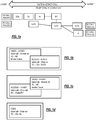
- FIGS. 1a to d illustrates schematically an example call between two parties over interfaces in multiple network layers.
- the interfaces implicated in the call are illustrated in FIG. 1a .
- the call is divided into two parts based on the calling and called party, respectively.
- Part A is a VoLTE call over 4G and IMS (IP Multimedia Subsystem) with mobility towards 3G
- Part B is a Legacy call located in 3G and 2G networks.
- Service Gateways SGs
- an lu CS interface between a Radio Network Controller (RNC) and a Circuit Switched Core Network (CS-CN)
- RNC Radio Network Controller
- CS-CN Circuit Switched Core Network
- S1 interface between eNodeBs and the Evolved Packet Core (EPC)
- Sv interface Session Initiation Protocol (SIP) interface
- a interface A interface
- Part B of the call suffers from a radio event after the communication has been established, resulting in an interruption of the call.
- a scenario of this type typically involves between 20 and 50 CDRs over RAN (Radio Access Network), EPC, CS, and IMS domains.
- Conventional analytics and network monitoring of CDRs generated by such a scenario results in isolated diagnoses of the cause for the call drop, as illustrated in FIGS. 1b to 1d .
- the dropped call is deemed to be due to the Core Network (DOOO - Destination Out of Order).
- the cause for Part B is diagnosed as a Radio failure (RIF - Radio Interface Failure).
- RRIF Radio Interface Failure
- the core network diagnosis is a release due to core network reasons (Nu - Normal Unspecified). From these isolated statements, it is difficult to link Part A of the call to Part B, let alone conclude that the call drop experienced in the A part was in reality caused by the radio failure observed in the B part.
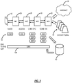
- FIG. 2 there is depicted two possible telecommunication session paths between a mobile communication device 10 and a remote party (not shown).
- the communication paths terminate either in a distant PLMN (Public Land Mobile Network) 40 or on the Internet 30.
- a number of network elements 20, NE1 to NE4, and interfaces carry the communication transaction.
- the interfaces include radio, Access, Core EPC (Evolved Packet Core), and Core IMS (IP Multimedia Subsystem Core).
- One or more CDRs 50 is generated at each of these interfaces and collected in a Data Gateway 60. While these CDRs carry information common to the telecommunication session, their format, time of generation, and frequency of generation vary according to the interface to which they relate.
- an end-to-end CDR 100 is compiled using the information contained in the multiple CDRs.
- the information collated from the multiple CDRs 50 generated in a telecommunication session may include, but is not limited to the following information: Root causes Core interface Identities Used network elements Core interface Destinations Valuable information from each interface Core interface routes Radio call trace Geolocation User Plane CDR Service provider Radio call trace radio condition Type of service Radio call trace Indoor / outdoor Quality of Experience (QoE) and usage
- FIG. 3 depicts schematically a system for generating end-to-end CDRs for telecommunication sessions according to an aspect of the present invention.
- a number of probes 70a - d are shown that generate one or more CDRs for each telecommunication session carried by the associated interface.
- the uppermost probe 70a generates CDRs related to the Global System for Mobile communications (GSM)/General Packet Radio Service (GPRS) and Universal Mobile Telecommunications Service (UMTS) signaling and user plane interfaces A lu and Gb.
- GSM Global System for Mobile communications
- GPRS General Packet Radio Service
- UMTS Universal Mobile Telecommunications Service
- the second probe 70b generates CDRs relating to EPC interfaces
- the third probe 70c emits CDRs relating to IMS interfaces
- the lowermost probe 70d collects radio call traces generated by network equipment, such as Base Transceiver System (BTS), NodeB, or Evolved NodeB (eNodeB) for each call and data session and emits CDRs.
- the CDRs are, in turn, collected in the gateway 60. While the elements 70 are all shown as probes in the illustrated example, it will be understood by those skilled in the art that CDRs may be generated by other network elements, in which case the CDRs will also be gathered by the gateway 60.
- the gateway 60 may decode the CDRs prior to feeding a CDR stream to the End-to-End CDR generator 80, which applies certain correlation rules to the CDRs in order to identify those CDRs relating to a single telecommunication session. Part of the extraction requires the identification of the CDR format, which is a function of the interface, or protocol, to which it refers.
- the End-to-End CDR generator 80 thus determines an identifier in each CDR that relates to its source interface. Based on this interface identifier, the End-to-End CDR generator 80 is able to map the information in the CDR to a common data model.
- Each end-to-end CDR contains information from the beginning to the end of one leg of a telecommunication session, e.g., either from an originating mobile phone or user to a terminating mobile phone or user, or vice versa.
- the end-to-end CDR 100 may be formatted in the common data model, which enables the one or more CDRs 50 to share a common format, namely a single end-to-end CDR 100 covering multiple CDRs 50.
- the CDRs 50 have a format, time of generation, frequency of generation, etc. that vary for different interfaces.
- the objective of the end-to-end CDR 100 is to present a single CDR that covers all CDRs 50 for the same session. Again, as described herein, a conventional session may have tens of different CDRs 50.
- the common data model can include various components, such as a meta portion which contains full session information over all interfaces, a macro portion which contains data summarizing each phase of the transaction over several interfaces (e.g., setup, HO, release, etc.), and a procedure portion which provides details across interfaces in the macro portion.
- the meta portion provides information related to Customer Experience Management (CEM) applications
- the macro portion provides information dedicated to Performance Management, Fault Management, deep troubleshooting, etc.
- CEM Customer Experience Management
- the end-to-end CDR 100 may be referred to as a "meta CDR.”
- Benefits of the end-to-end CDR 100 include automatic ordering of the different CDRs 50 in the end-to-end CDR 100 for the overall session, mapping of the common data model for different and heterogenous domains crossed by the session, enrichment of mandatory information such as International Mobile Subscriber Identity (IMSI), Mobile Station International Subscriber Directory Number (MSISDN), etc. Further, the end-to-end CDR 100 provides an automatic correlation between the A part and the B part, such as in FIG. 1 . The end-to-end CDR 100 enables automated diagnosis for relevant root cause issues for both parties, based on intelligent rules.
- IMSI International Mobile Subscriber Identity
- MSISDN Mobile Station International Subscriber Directory Number
- end-to-end CDR 100 enables unique metrics (e.g., counters, Key Performance Indicators (KPIs), etc.) for QoE and QoS.
- KPIs Key Performance Indicators
- the end-to-end CDR 100 enables disparate CDRs 50 from different probe 70 suppliers, at different protocols, at different interfaces, etc.
- the gateway 60 and End-to-End CDR generator 80 depicted in FIG. 3 are preferably implemented on one or more processors with associated memory, such as illustrated in the processing device 300 of FIG. 10 .
- the memory stores instructions, in the form of a computer program, for causing the processor or processors to carry out the steps described herein.
- the memory may be any suitable type of computer-readable memory and may be of volatile and/or non-volatile type.
- the processor may be any suitable type of computation unit, e.g., a microprocessor, Digital Signal Processor (DSP), Field Programmable Gate Array (FPGA), or Application Specific Integrated Circuit (ASIC) or any other form of circuitry.
- DSP Digital Signal Processor
- FPGA Field Programmable Gate Array
- ASIC Application Specific Integrated Circuit
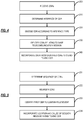
- the system, and specifically gateway 60 receives the CDRs.
- the End-to-End CDR generator 80 determines the interface to which the CDR relates.
- Each CDR includes an identifier associated with the interface and or protocol to which the CDR relates.
- the interface and/or protocol of the CDR determines the format of the CDR.
- a mapping is done for predefined interfaces regardless of the information the CDR could contain. In a telecommunication session using multiple network elements and interfaces, it is important that the CDRs are correctly decoded to ensure the successful extraction of the relevant information from that portion of the call or session.
- Step 210 identifies and stores the CDRs of the interfaces that will be used for End-to-End CDR generation. Step 210 reduces the data volume to decode and limits the resources needed for the correlation.
- the End-to-End CDR generator 80 decodes the CDRs according to the identified interface. As part of this decoding, the CDR information is preferably mapped to an End-to-End CDR common data model for subsequent processing.
- the End-to-End CDR generator 80 identifies the CDRs that relate to the same telecommunication session. This may be achieved by correlating the CDRs according to subscriber identities, such as the IMSI.
- Further correlation parameters include the start and end timestamps of a telecommunication session, the location, the root cause of a fault, etc.
- a CDR may be associated with a telecommunication session if it has a timestamp within the window of the telecommunication session (with a certain tolerance).
- data from identified CDRs is incorporated into an End-to-End CDR representative of one leg of a telecommunication session, i.e., one direction of a call, text, or data session, also referred to as Mobile Originated (MO) or Mobile Terminated (MT).
- MO Mobile Originated
- MT Mobile Terminated
- the CDRs are received continuously from the probes and network elements 70 as they are generated.
- the CDRs may be stored prior to processing or processed as and when they arrive to generate a current record of the state of the network, and hence to allow any fault and its location to be identified and, if possible, mitigated without minimal delay.
- FIG. 5 illustrates a supplemental process that may be performed between steps 230 and 240 of the process of FIG. 4 in accordance with a further aspect of the present invention.
- FIG. 5 starts at step 231 with the determination of the sequence or order of the CDRs identified as relating to the same telecommunication session.
- the CDRs are preferably coded in a common data model following step 230 of FIG. 4 .
- the sequence of a CDR in relation to other identified CDRs may be determined by examining the communication timestamp. In any telecommunication session, CDRs will record events that occur in succession as the call or data session progresses through the network. While the CDR may not is immediate, it contains timestamp data concerning the telecommunication session. Hence, the chronological order of the CDRs can be determined and the CDRs re-ordered in this manner. This is performed in step 232.
- Reordering the CDRs therefore, includes reordering the identified CDRs into a sequence corresponding to a chronological order in which each CDR is linked from a communication perspective, regardless of when they could have been generated depending on their source.
- the re-ordered CDRs are examined for faults or events that affect a telecommunication session to determine which CDR reports a fault that triggered a session release.
- this is the first recorded fault or event in the reordered sequence of CDRs as any CDR generated downstream of a detected fault will report the same fault or event or report a consequence of that fault.
- an algorithm analyses the end time, event, and causes in the different CDRs on the different interfaces to determine the event that triggered call release. This may be based on the timing of the release, such as the earliest fault reported within a certain time window of the session release. Alternatively, this may be based on specific flagging events that may be considered as a reason for call release.
- the data relating to the fault or call release event is incorporated in the End-to-End CDR. This includes the fault location, i.e., the interface and network element responsible for or implicated in the call release as well as the cause as reported in the original CDR.
- the CDRs 50 are generated by different network elements (e.g., probes 70, network elements 20, etc.) at different times during a given session.
- the CDRs 50 are streamed to the distributed system 300 where streaming means sending the CDRs 50 as they are generated to the distributed system 300.
- the distributed system 300 is configured to process the streamed CDRs as they are received for a given session, as opposed to waiting for all CDRs 50 to be received for the given session and performing post processing.
- the distributed system 300 By receiving the streamed CDRs 50 and processing them as they are received, the distributed system 300 incrementally builds the end-to-end CDR 100 from the streamed CDRs 50, in a manner where the end-to-end CDR 100 is available as the given session concludes (or shortly thereafter), i.e., without significant latency. Note, the streamed CDRs 50 may be received in any order as well with the distributed system 300 configured to manage the order in the creation of the end-to-end CDR 100.
- the End-to-End Call Detail Records generated according to the invention relate to a single leg of a telecommunications session.
- the End-to-End CDR generator 80 associates the two End-to-End CDRs with one another by incorporating identifying information from one End-to-End CDR in that of the other, and vice versa. Preferably, this information is included as remote subscriber information.
- the following provides an example of an end-to-end CDR 100 for a voice service, including examples of the possible information included therein.
- Subscriber ID IMSI/MSISDN International Mobile Equipment Identity (IMEI)/Device Location of A party Call Info Call type/direction Remote MSISDN Location of B party Efficiency Last cause of A party Root cause category
- one end-to-end CDR 100 corresponds to the activity from the beginning to the end of one leg of a call (Mobile Originated (MO) or Mobile Terminated (MT) and gathers important information taken in CDRs 50 of the different interfaces.
- MO Mobile Originated
- MT Mobile Terminated
- two voice end-to-end CDRs 100 can be generated if both ends of the call corresponding to users on the network.
- the voice end-to-end CDRs 100 of both legs are associated so that a part of the information of one leg is included in the other leg's end-to-end CDR 100 as remote subscriber information.
- the release cause of one leg can also be used as the root release cause of the other leg in case of a drop for instance.
- a partial end-to-end CDR 100 is also emitted in case of call setup success in order to be used for analytics calculations to minimize the delay for statistic generation.
- a voice end-to-end CDR 100 can include legacy calls (2G or 3G), Circuit Switched Fallback (CSFB) calls, IMS calls (4G or Wi-Fi), Inter Radio Access Technology (RAT) Handover (HO) calls: 3G to 2G, 2G to 3G, Single Radio Voice Call Continuity (SRVCC) to 2G or 3G, 4G to Wi-Fi, Wi-Fi to 4G, etc.
- legacy calls (2G or 3G
- CSFB Circuit Switched Fallback
- IMS calls (4G or Wi-Fi)
- RAT Inter Radio Access Technology
- HO Handover
- SRI Send Routing Information
- PRN Private Roaming Number
- the end-to-end CDR 100 can be used for performance, Service Oriented Communications (SOC), CEM monitoring, and various other use cases.
- SOC Service Oriented Communications
- CEM CEM monitoring
- the end-to-end CDR 100 an be used for Customer-Centric with Quality of Experience (QoE), including Customer Care Diagnosis : Overall activity including Radio Coverage Experience, Customer Management: Fleet management, Customer journey, and SQM : Service Quality Management.
- QoE Quality of Experience
- Customer Care Diagnosis Overall activity including Radio Coverage Experience
- Customer Management Fleet management
- Customer journey Customer journey
- SQM Service Quality Management.
- the end-to-end CDR 100 can be used Network Performance Analytics including Voice & Mobility Performance (e.g., VoLTE/VoWIFI), Idle Mobility & registration (e.g., customer habits and Idle location per RAT, registration to the network for local subs and roamers (inbound and outbound), etc.), Mobility Connected, SMS & Messaging, Unstructured Supplementary Service Data (USSD), and Data Bearer.
- Voice & Mobility Performance e.g., VoLTE/VoWIFI
- Idle Mobility & registration e.g., customer habits and Idle location per RAT, registration to the network for local subs and roamers (inbound and outbound), etc.
- Mobility Connected e.g., SMS & Messaging, Unstructured Supplementary Service Data (USSD), and Data Bearer.
- USSD Unstructured Supplementary Service Data
- Data Bearer Various other use cases are also contemplated such as behavior monitoring, etc.
- An aspect of the end-to-end CDR 100 includes the data-agnostic capability from a CDR 50 perspective, namely the ability to support the probes 70 or interfaces from any protocol, any format, any vendor, etc. Such a feature is enabled via the common data model format, which allows different CDRs to coexist in the end-to-end CDR 100.
- FIG. 6 depicts schematically an example implementation of a distributed system 300 for generating end-to-end CDRs 100 for telecommunication sessions according to an aspect of the present invention.
- the distributed system 300 is presented as an example of one implementation, and those of ordinary skill in the art will recognize other embodiments are contemplated.
- the distributed system 300 can be a distributed computing system that is capable of receiving streaming data, e.g., the CDRs 50 as generated, and processing the streamed data incrementally to create the end-to-end CDRs 100 on the fly.
- FIG. 6 includes includes probes 70-1, 70-2.
- the probes 70-1 can be Core CS/IMS-based probes including virtual probes (vprobes), providing information related to MAP, ISUP, SIP, DNS, ENUM CAP, RX, etc.
- the probes 70-2 can be EPC-based probes including vprobes, providing information related to various interfaces.
- the outputs, namely the CDRs 50, of the probes 70-1, 70-2 are provided to hubs 302, 304, and streamed to the gateway 60.
- the gateway 60 can provide the streaming CDRs 50 to the distributed system 300 that includes various processing devices 306, 308, 310, 312.
- the distributed system 300 can include Apache Kafka, Arvo, Spark, and Hive in an embodiment; other techniques are also contemplated.
- the processing device 306 can receive the streaming CDRs 50, provide the streaming CDRs 50 to the processing devices 308 for decoding (e.g., data normalization).
- the output of the processing devices 308 can be shuffled, such as according to IMSI and provided to the processing devices 310 for updating the context of specific end-to-end CDRs 100, such as based on the IMSI, and the output provided to a database 314 for storage and retrieval.
- an aspect of the present invention is to create the end-to-end CDRs 100 substantially in real-time, i.e., with minimum latency.
- the CDRs 50 e.g., from the problems 70-1, 70-2 arrive unordered, with some missing, with some latency, etc. to the distributed system 300.
- the distributed system 300 is configured to manage these constraints, namely receive the CDRs 50 in a streaming manner and incrementally build corresponding end-to-end CDRs 100.
- the CDRs 50 are initially read by different processes in the distributed system 300 without preconception of the corresponding associated user.
- the interesting information in each CDR 50 is then routed to creation contexts on the processing devices 310 based on a single key.
- the key is some unique identifier present in every input CDR 50.
- the key can be the IMSI, and other values are contemplated. If the key is unavailable, there can be a pre-enrichment process for that CDR 50 to obtain such key. Also, if one CDR 50 can be determined as corresponding to more than one subscriber (e.g., mobile to mobile calls), then that CDR the has to be duplicated to be associated each with a different key.
- the end-to-end CDR 100 creation processes handles CDRs 50 individually for each subscriber.
- Each input CDR 50 is initially considered as a separate end-to-end CDR 100 whose fields are filled with the information available in the CDR 50 including the root failure cause and faulty equipment data.
- a set of telecom-oriented rules then allows the distributed system 300 to identify temporary CDRs 50 actually corresponding to the same activity, the corresponding data is then merged into a single end-to-end CDR 100 context according to some merging rules that include a method for determining the most accurate root cause data based on timestamps and cause types.
- the useful data has to be transmitted to the context for this user each time new interesting data is retrieved (e.g., new root cause information).
- new interesting data e.g., new root cause information.
- the actual generation of the end-to-end CDR 100 in the output of the process is driven by timeouts whose duration depends on the current state of the activity and the level of completeness of the data that was gathered so far.
- FIGS. 7 and 8 depict illustrative examples of two voice end-to-end CDRs 100. Specifically, FIG. 7 depicts examples of various CDRs 50 correlated into an end-to-end CDR 100 for an MT CSFB call. FIG. 8 depicts examples of various CDRs 50 correlated for an MT VoIMS call with SRVCC. As mentioned herein, information gathered on the different interfaces, for the different protocols, and corresponding to the end-to-end call are gathered in a single data structure in the end-to-end CDR 100, including:
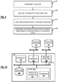
- FIG. 9 illustrates a supplemental process associated with the supplemental process of FIG. 5 for determining root (release) cause via the end-to-end CDRs 100.
- FIG. 9 starts with an end-to-end CDR 100 at step 251.
- the process analyses the end time, event, and causes of the different CDRs 50 on the different interfaces to determine the one that actually triggered the call release. This determination can be based on the timing of releases, such as the earliest message preceding the actual call release, within a certain time tolerance. This determination can also be based on specific flagging of events that can be considered as a reason for the call end or not.
- This determination can further include an application of one or more rules to the CDR at step 253 to diagnosis the root cause.
- the end-to-end CDR 100 can be updated to indicate the interface and network equipment responsible for the release and the actual release cause. This cause is then used to categorize the call release reason.
- a single telecommunications session can have, for example, 20 to 50 different CDRs associated with it.
- CDRs For the end-to-end CDR 100, there is a requirement to develop so-called merge rules for determining whether two different CDRs 50 apply to the same telecommunication session. Further, these merge rules can be used to determine information for the end-to-end CDR 100 These merge rules can be implemented in the distributed system 300 to determine the CDRs 50 should be assigned to a specific end-to-end CDR 50.
- One example merge rule can include a SIP call ID matching.
- two different CDRs 50 with at least one SIP call ID in common may be merged into the same end-to-end CDR 100.
- Another example merge rule can include a SIP charging ID.
- two different CDRs 50 with at least one SIP charging ID in common may be merged into the same end-to-end CDR 100.
- the Core Start Event may be different than from a SIP Register.
- Another example merge rule can include a CSFB Merge rule where the call start on an A interface or lu interface CDR 50 is merged with that of an S1 or SGs interface.
- Another example merge rule can include a merge of an S1 User Equipment (UE) Context Release or HO with CSFB.
- UE User Equipment
- Another example merge rule can relate to RAN mobility.
- the rule can relate to one CDR 50 being an outgoing mobility and another CDR 50 matching the start of incoming mobility.
- Also related to RAN mobility there can be merge rules related to the same start time (with a tolerance) and matching destinations numbers or remote IMSI.
- Yet another example merge rule can include matching Mobile Station Roaming Number (MSRN) numbers.
- MSRN Mobile Station Roaming Number
- merge rules can be any conditions where met are indicative that two different CDRs 50 are related. Further, the merge rules can define which information is used in the end-to-end CDR 100, such as related to failure, call times, etc.
- FIG. 10 is a block diagram of a processing device 400, which may be used to implement the systems and methods described herein.
- the processing device 400 may be a digital computer that, in terms of hardware architecture, generally includes a processor 402, input/output (I/O) interfaces 404, a network interface 406, a data store 408, and memory 410. It should be appreciated by those of ordinary skill in the art that FIG. 10 depicts the processing device 400 in an oversimplified manner, and a practical embodiment may include additional components and suitably configured processing logic to support known or conventional operating features that are not described in detail herein.
- the processing device 400 is a building block of the devices 60, 302, 304, 308, 310, 312, 314 associated with the distributed system 300.
- the components (402, 404, 406, 408, and 410) are communicatively coupled via a local interface 412.
- the local interface 412 may be, for example, but not limited to, one or more buses or other wired or wireless connections, as is known in the art.
- the local interface 412 may have additional elements, which are omitted for simplicity, such as controllers, buffers (caches), drivers, repeaters, and receivers, among many others, to enable communications. Further, the local interface 412 may include address, control, and/or data connections to enable appropriate communications among the aforementioned components.
- the processor 402 is a hardware device for executing software instructions.
- the processor 402 may be any custom made or commercially available processor, a central processing unit (CPU), an auxiliary processor among several processors associated with the processing device 400, a semiconductor-based microprocessor (in the form of a microchip or chipset), or generally any device for executing software instructions.
- the processor 402 is configured to execute software stored within the memory 410, to communicate data to and from the memory 410, and to generally control operations of the processing device 400 pursuant to the software instructions.
- the I/O interfaces 404 may be used to receive user input from and/or for providing system output to one or more devices or components.
- I/O interfaces 404 may include, for example, a serial port, a parallel port, a Small Computer System Interface (SCSI), a Serial ATA (SATA), a fibre channel, Infiniband, iSCSI, a PCI Express interface (PCI-x), an Infrared (IR) interface, a Radio Frequency (RF) interface, a Universal Serial Bus (USB) interface, or the like.
- SCSI Small Computer System Interface
- SATA Serial ATA
- PCI-x PCI Express interface
- IR Infrared
- RF Radio Frequency
- USB Universal Serial Bus
- the network interface 406 may be used to enable the processing device 400 to communicate over the network 120, etc.
- the network interface 406 may include, for example, an Ethernet card or adapter or a Wireless Local Area Network (WLAN) card or adapter.
- the network interface 406 may include address, control, and/or data connections to enable appropriate communications on the network.
- a data store 408 may be used to store data.
- the data store 408 may include any of volatile memory elements (e.g., random access memory (RAM, such as DRAM, SRAM, SDRAM, and the like)), nonvolatile memory elements (e.g., ROM, hard drive, tape, CDROM, and the like), and combinations thereof.
- the data store 408 may incorporate electronic, magnetic, optical, and/or other types of storage media.
- the data store 408 may be located internal to the processing device 400, such as, for example, an internal hard drive connected to the local interface 412 in the processing device 400. Additionally, in another embodiment, the data store 408 may be located external to the processing device 400, such as, for example, an external hard drive connected to the I/O interfaces 404 (e.g., SCSI or USB connection). In a further embodiment, the data store 408 may be connected to the processing device 400 through a network, such as, for example, a network-attached file server.
- the memory 410 may include any of volatile memory elements (e.g., random access memory (RAM, such as DRAM, SRAM, SDRAM, etc.)), nonvolatile memory elements (e.g., ROM, hard drive, tape, CDROM, etc.), and combinations thereof. Moreover, the memory 410 may incorporate electronic, magnetic, optical, and/or other types of storage media. Note that the memory 410 may have a distributed architecture, where various components are situated remotely from one another, but can be accessed by the processor 402.
- the software in memory 410 may include one or more software programs, each of which includes an ordered listing of executable instructions for implementing logical functions.
- the software in the memory 410 includes a suitable operating system (O/S) 414 and one or more programs 416.
- O/S operating system
- the operating system 414 essentially controls the execution of other computer programs, such as the one or more programs 416, and provides scheduling, input-output control, file and data management, memory management, and communication control and related services.
- the one or more programs 416 may be configured to implement the various processes, algorithms, methods, techniques, etc. described herein.
- processors such as microprocessors; Central Processing Units (CPUs); Digital Signal Processors (DSPs): customized processors such as Network Processors (NPs) or Network Processing Units (NPUs), Graphics Processing Units (GPUs), or the like; Field-Programmable Gate Arrays (FPGAs); and the like along with unique stored program instructions (including both software and firmware) for control thereof to implement, in conjunction with certain non-processor circuits, some, most, or all of the functions of the methods and/or systems described herein.
- processors such as microprocessors; Central Processing Units (CPUs); Digital Signal Processors (DSPs): customized processors such as Network Processors (NPs) or Network Processing Units (NPUs), Graphics Processing Units (GPUs), or the like; Field-Programmable Gate Arrays (FPGAs); and the like along with unique stored program instructions (including both software and firmware) for control thereof to implement, in conjunction with certain non-processor circuits, some, most, or all
- circuitry configured to
- logic configured to
- some embodiments may include a non-transitory computer-readable medium having instructions stored thereon for programming a computer, server, appliance, device, processor, circuit, etc. to perform functions as described and claimed herein.
- Examples of such non-transitory computer-readable medium include, but are not limited to, a hard disk, an optical storage device, a magnetic storage device, a Read-Only Memory (ROM), a Programmable ROM (PROM), an Erasable PROM (EPROM), an Electrically EPROM (EEPROM), Flash memory, and the like.
- software can include instructions executable by a processor or device (e.g., any type of programmable circuitry or logic) that, in response to such execution, cause a processor or the device to perform a set of operations, steps, methods, processes, algorithms, functions, techniques, etc. as described herein for the various embodiments.
- a processor or device e.g., any type of programmable circuitry or logic
Landscapes
- Engineering & Computer Science (AREA)
- Signal Processing (AREA)
- Computer Networks & Wireless Communication (AREA)
- Business, Economics & Management (AREA)
- General Business, Economics & Management (AREA)
- Multimedia (AREA)
- Accounting & Taxation (AREA)
- Mobile Radio Communication Systems (AREA)
- Telephonic Communication Services (AREA)
Applications Claiming Priority (1)
| Application Number | Priority Date | Filing Date | Title |
|---|---|---|---|
| US201862777882P | 2018-12-11 | 2018-12-11 |
Publications (2)
| Publication Number | Publication Date |
|---|---|
| EP3668014A1 true EP3668014A1 (de) | 2020-06-17 |
| EP3668014B1 EP3668014B1 (de) | 2022-03-30 |
Family
ID=69063604
Family Applications (1)
| Application Number | Title | Priority Date | Filing Date |
|---|---|---|---|
| EP19215275.9A Active EP3668014B1 (de) | 2018-12-11 | 2019-12-11 | Ende-zu-ende-sitzungsbezogene anrufdetailaufzeichnung |
Country Status (2)
| Country | Link |
|---|---|
| US (1) | US11025782B2 (de) |
| EP (1) | EP3668014B1 (de) |
Cited By (3)
| Publication number | Priority date | Publication date | Assignee | Title |
|---|---|---|---|---|
| US20240080393A1 (en) * | 2022-09-07 | 2024-03-07 | EXFO Solutions SAS | Mme writer and identity service for ran parser |
| EP4336889A1 (de) * | 2022-09-07 | 2024-03-13 | EXFO Solutions SAS | Trace-empfänger und mme-empfängerdienst für ran-parser |
| EP4396684A4 (de) * | 2021-08-31 | 2025-02-26 | Rakuten Mobile, Inc. | Leistungsanalyse eines öffentlichen landfunknetzes zwischen endpunkten |
Families Citing this family (12)
| Publication number | Priority date | Publication date | Assignee | Title |
|---|---|---|---|---|
| US11025782B2 (en) * | 2018-12-11 | 2021-06-01 | EXFO Solutions SAS | End-to-end session-related call detail record |
| EP3726825B1 (de) * | 2019-04-16 | 2023-11-08 | Bics Sa/Nv | System und verfahren zur betrugserkennung im internationalen telekommunikationsverkehr |
| US12200523B2 (en) * | 2020-03-19 | 2025-01-14 | Telefonaktiebolaget Lm Ericsson (Publ) | Monitoring a communication network |
| US11202181B1 (en) * | 2020-05-28 | 2021-12-14 | At&T Intellectual Property I, L.P. | Systems and methods for identifying service type of data usage on 5G new radio (NR) radio access technology type |
| CN112153227A (zh) * | 2020-09-25 | 2020-12-29 | 马宇轩 | 基于动态配置的电话接口系统 |
| CN112491595B (zh) * | 2020-11-12 | 2023-04-07 | 杭州迪普信息技术有限公司 | 故障区域定位方法、装置、设备及计算机可读存储介质 |
| CN113490202B (zh) * | 2021-07-23 | 2024-07-09 | 恒安嘉新(北京)科技股份公司 | 一种语音话单的合成方法、装置、计算机设备和存储介质 |
| US20240080392A1 (en) * | 2022-09-07 | 2024-03-07 | EXFO Solutions SAS | Link generation for ran parser |
| US20240205339A1 (en) * | 2022-09-07 | 2024-06-20 | EXFO Solutions SAS | Procedure cdr generation for a ran parser |
| US12095628B2 (en) * | 2022-10-19 | 2024-09-17 | T-Mobile Usa, Inc. | Machine learning system for predicting network abnormalities |
| US11943091B1 (en) * | 2022-10-26 | 2024-03-26 | Cisco Technology, Inc. | Distributed diagnostics for network wide route policy analyzer and other use cases |
| US20250219924A1 (en) * | 2023-12-27 | 2025-07-03 | Dish Wireless L.L.C. | Call trace and trace file transfer in a cloud-based 5g communication network |
Citations (4)
| Publication number | Priority date | Publication date | Assignee | Title |
|---|---|---|---|---|
| US6731730B1 (en) * | 1999-07-12 | 2004-05-04 | Ectel Ltd. | Method and system for creating combined call detail records databases (CDR) in management systems of communication networks |
| US7424103B2 (en) | 2004-08-25 | 2008-09-09 | Agilent Technologies, Inc. | Method of telecommunications call record correlation providing a basis for quantitative analysis of telecommunications call traffic routing |
| US20100128860A1 (en) * | 2008-11-25 | 2010-05-27 | At&T Intellectual Property I, L.P. | Methods, computer program products, and systems for managing voice over internet protocol (voip) network elements |
| US20140269445A1 (en) * | 2013-03-15 | 2014-09-18 | Vonage Network, Llc | Systems and methods for matching call detail records for the same communication generated by different elements of an ip telephony system |
Family Cites Families (41)
| Publication number | Priority date | Publication date | Assignee | Title |
|---|---|---|---|---|
| US6714979B1 (en) | 1997-09-26 | 2004-03-30 | Worldcom, Inc. | Data warehousing infrastructure for web based reporting tool |
| US6052448A (en) | 1997-12-23 | 2000-04-18 | Northern Telecom Limited | Method for flexible formatting of call detail records and switching system incorporating same |
| US6298123B1 (en) | 1998-03-26 | 2001-10-02 | Bell Atlantic Network Services, Inc. | Interconnect traffic tracking |
| US6249572B1 (en) | 1998-06-08 | 2001-06-19 | Inet Technologies, Inc. | Transaction control application part (TCAP) call detail record generation in a communications network |
| US6912230B1 (en) | 1999-02-05 | 2005-06-28 | Tecore | Multi-protocol wireless communication apparatus and method |
| EP1173969B1 (de) | 1999-04-05 | 2007-04-11 | Tekelec | Verfahren und system zur leitweglenkung von mit portierten teilnehmern assozierten signalisierungsnachrichten in einem kommunikationsnetzwerk |
| US6400813B1 (en) | 1999-10-25 | 2002-06-04 | Inrange Technologies, Inc. | Mediation system for a telephone network |
| US6614893B1 (en) | 2000-02-24 | 2003-09-02 | Richard S. Paiz | Parallel computer network and method for telecommunications network simulation to route calls and continuously estimate call billing in real time |
| US6891938B1 (en) | 2000-11-07 | 2005-05-10 | Agilent Technologies, Inc. | Correlation and enrichment of telephone system call data records |
| US20020199182A1 (en) | 2001-02-15 | 2002-12-26 | Susan Whitehead | Method and apparatus providing convergent solution to end-to end, adaptive business application management |
| US7254109B2 (en) | 2002-07-12 | 2007-08-07 | Baypackets, Inc. | Fault tolerant correlation engine method and system for telecommunications networks |
| GB0221925D0 (en) | 2002-09-20 | 2002-10-30 | Neural Technologies Ltd | A system for the retrospective classification of archived events |
| EP1604514A4 (de) | 2003-02-27 | 2006-06-14 | Tekelec Us | Verfahren und systeme zur automatischen und präzisen rufdetailaufzeichnung für anrufe in verbindung mit portierten teilnehmern |
| US7203291B2 (en) | 2004-06-01 | 2007-04-10 | Agilent Technologies, Inc. | Apparatus and method for generating call information data for calls on long duration |
| WO2006009929A2 (en) | 2004-06-18 | 2006-01-26 | Tekelec | METHODS, SYSTEMS, AND COMPUTER PROGRAM PRODUCTS FOR SELECTING OR GENERATING A SINGLE CALL DETAIL RECORD (CDR) FROM A PLURALITY OF CDRs ASSOCIATED WITH A CALL HAVING A PLURALITY OF LEGS |
| US7599359B1 (en) | 2004-12-14 | 2009-10-06 | At&T Corp. | Method and apparatus for monitoring end-to-end performance in a network |
| US8126123B2 (en) | 2007-02-27 | 2012-02-28 | Alcatel Lucent | Pre-biller in internet protocol multimedia subsystem (IMS) charging gateway function (CGF) |
| US8792482B2 (en) | 2008-12-09 | 2014-07-29 | At&T Intellectual Property I, L.P. | Method and apparatus for correlation of data sources in a Voice over Internet Protocol network |
| US8565395B2 (en) | 2009-12-28 | 2013-10-22 | At&T Intellectual Property I, L.P. | VoIP master call detail record |
| US9148523B2 (en) | 2010-04-02 | 2015-09-29 | At&T Intellectual Property I, L.P. | Method and apparatus for managing a network |
| US9042908B2 (en) | 2012-05-08 | 2015-05-26 | International Business Machines Corporation | Identifying purpose-based origin-destination using call detailed records |
| US9414248B2 (en) | 2013-03-15 | 2016-08-09 | Movik Networks, Inc. | System and methods for estimation and improvement of user, service and network QOE metrics |
| US8731162B1 (en) | 2013-03-15 | 2014-05-20 | Vonage Network, Llc | Systems and methods for matching call detail records for the same communication generated by different elements of an IP telephony system |
| US20150310336A1 (en) | 2014-04-29 | 2015-10-29 | Wise Athena Inc. | Predicting customer churn in a telecommunications network environment |
| US9647956B2 (en) | 2014-09-30 | 2017-05-09 | Vonage America Inc. | Method and systems for dynamic allocation of network resources |
| US9369569B1 (en) * | 2015-03-27 | 2016-06-14 | Verizon Patent And Licensing Inc. | End-to-end voice-over-long term evolution (VoLTE) call record |
| US10397043B2 (en) | 2015-07-15 | 2019-08-27 | TUPL, Inc. | Wireless carrier network performance analysis and troubleshooting |
| EP3342146B1 (de) | 2015-08-28 | 2021-03-31 | Telefonaktiebolaget LM Ericsson (publ) | Detaillierte anrufdatensätze für voice-over-lte-anrufe |
| US10164850B2 (en) | 2015-09-10 | 2018-12-25 | Tupl, Inc | Wireless communication data analysis and reporting |
| US9749840B1 (en) | 2015-11-19 | 2017-08-29 | Cisco Technology, Inc. | Generating and analyzing call detail records for various uses of mobile network resources |
| US10708795B2 (en) | 2016-06-07 | 2020-07-07 | TUPL, Inc. | Artificial intelligence-based network advisor |
| US9992123B2 (en) | 2016-06-30 | 2018-06-05 | Verizon Patent And Licensing Inc. | Methods and systems for evaluating voice over Wi-Fi (VoWiFi) call quality |
| US10339456B2 (en) | 2017-01-05 | 2019-07-02 | T-Mobile Usa, Inc. | Machine learning-based troubleshooting of VoLTE calls |
| US10061637B1 (en) | 2017-01-19 | 2018-08-28 | Amdocs Development Limited | System, method, and computer program for automatic root cause analysis |
| CN108462785B (zh) | 2017-02-21 | 2020-02-21 | 中国移动通信集团浙江有限公司 | 一种恶意呼叫电话的处理方法及装置 |
| US11018958B2 (en) | 2017-03-14 | 2021-05-25 | Tupl Inc | Communication network quality of experience extrapolation and diagnosis |
| US10455438B2 (en) | 2017-03-30 | 2019-10-22 | T-Mobile Usa, Inc. | Telecom monitoring and analysis system |
| US10177964B2 (en) * | 2017-04-19 | 2019-01-08 | Netscout Systems, Inc | System and method for accurate reporting of fault for failed internet protocol-based calls |
| CN107451192A (zh) | 2017-06-28 | 2017-12-08 | 国家计算机网络与信息安全管理中心 | 一种基于分解聚合的电信诈骗电话的分类检测方法 |
| US11138619B2 (en) | 2017-09-06 | 2021-10-05 | T-Mobile Usa, Inc. | Using digital traffic data for analysis |
| US11025782B2 (en) * | 2018-12-11 | 2021-06-01 | EXFO Solutions SAS | End-to-end session-related call detail record |
-
2019
- 2019-12-10 US US16/708,904 patent/US11025782B2/en active Active
- 2019-12-11 EP EP19215275.9A patent/EP3668014B1/de active Active
Patent Citations (4)
| Publication number | Priority date | Publication date | Assignee | Title |
|---|---|---|---|---|
| US6731730B1 (en) * | 1999-07-12 | 2004-05-04 | Ectel Ltd. | Method and system for creating combined call detail records databases (CDR) in management systems of communication networks |
| US7424103B2 (en) | 2004-08-25 | 2008-09-09 | Agilent Technologies, Inc. | Method of telecommunications call record correlation providing a basis for quantitative analysis of telecommunications call traffic routing |
| US20100128860A1 (en) * | 2008-11-25 | 2010-05-27 | At&T Intellectual Property I, L.P. | Methods, computer program products, and systems for managing voice over internet protocol (voip) network elements |
| US20140269445A1 (en) * | 2013-03-15 | 2014-09-18 | Vonage Network, Llc | Systems and methods for matching call detail records for the same communication generated by different elements of an ip telephony system |
Cited By (6)
| Publication number | Priority date | Publication date | Assignee | Title |
|---|---|---|---|---|
| EP4396684A4 (de) * | 2021-08-31 | 2025-02-26 | Rakuten Mobile, Inc. | Leistungsanalyse eines öffentlichen landfunknetzes zwischen endpunkten |
| US12382320B2 (en) | 2021-08-31 | 2025-08-05 | Rakuten Mobile, Inc. | End-to-end public land mobile network performance analysis |
| US20240080393A1 (en) * | 2022-09-07 | 2024-03-07 | EXFO Solutions SAS | Mme writer and identity service for ran parser |
| EP4336814A1 (de) * | 2022-09-07 | 2024-03-13 | EXFO Solutions SAS | Mme-schreiber und identitätsdienst für ran-parser |
| EP4336889A1 (de) * | 2022-09-07 | 2024-03-13 | EXFO Solutions SAS | Trace-empfänger und mme-empfängerdienst für ran-parser |
| US12549638B2 (en) | 2022-09-07 | 2026-02-10 | Tc France S.A.S. | Trace receiver and MME receiver service for RAN parser |
Also Published As
| Publication number | Publication date |
|---|---|
| US11025782B2 (en) | 2021-06-01 |
| EP3668014B1 (de) | 2022-03-30 |
| US20200186651A1 (en) | 2020-06-11 |
Similar Documents
| Publication | Publication Date | Title |
|---|---|---|
| EP3668014B1 (de) | Ende-zu-ende-sitzungsbezogene anrufdetailaufzeichnung | |
| US11882005B2 (en) | Predictive scoring based on key performance indicators in telecommunications system | |
| US8761757B2 (en) | Identification of communication devices in telecommunication networks | |
| US9924386B2 (en) | Method and system for wireless network optimization and remote control of mobile handset operation | |
| CN101883375B (zh) | 一种网络监控方法及其系统 | |
| CN110536314B (zh) | 语音质量的确定方法、装置、设备及介质 | |
| US11425557B2 (en) | Monitoring in a 5G non-standalone architecture to determine bearer type | |
| US11397606B2 (en) | Systems and methods for automated monitoring and troubleshooting of unknown dependencies in a virtual infrastructure | |
| US20240214844A1 (en) | Wireless Communication Network Voice Quality Monitoring | |
| EP2991303B1 (de) | Sitzungszuordnungsverfahren, -vorrichtung und system | |
| US10742485B2 (en) | Method for determining a sequence of events, a determination device for determining a sequence of events, and a providing device | |
| US20120163194A1 (en) | Handling Alarms Based On User Session Records | |
| CN114222284B (zh) | 终端设备识别方法、装置及可读存储介质 | |
| US10015690B2 (en) | Technique for call processing and analysis | |
| CN106255132A (zh) | 一种设置跟踪区的方法及装置 | |
| CN100401828C (zh) | 一种获取信令流程中信息的方法 | |
| CN102421110B (zh) | 端到端关联的实现方法和装置 | |
| US11451671B2 (en) | Identification of 5G Non-Standalone Architecture traffic on the S1 interface | |
| US20240205339A1 (en) | Procedure cdr generation for a ran parser | |
| CN109661028B (zh) | 跟踪区码的更新方法、系统、电子设备和存储介质 | |
| WO2021197603A1 (en) | Collection of symptom data for disaggregated network elements |
Legal Events
| Date | Code | Title | Description |
|---|---|---|---|
| PUAI | Public reference made under article 153(3) epc to a published international application that has entered the european phase |
Free format text: ORIGINAL CODE: 0009012 |
|
| STAA | Information on the status of an ep patent application or granted ep patent |
Free format text: STATUS: THE APPLICATION HAS BEEN PUBLISHED |
|
| AK | Designated contracting states |
Kind code of ref document: A1 Designated state(s): AL AT BE BG CH CY CZ DE DK EE ES FI FR GB GR HR HU IE IS IT LI LT LU LV MC MK MT NL NO PL PT RO RS SE SI SK SM TR |
|
| AX | Request for extension of the european patent |
Extension state: BA ME |
|
| STAA | Information on the status of an ep patent application or granted ep patent |
Free format text: STATUS: REQUEST FOR EXAMINATION WAS MADE |
|
| 17P | Request for examination filed |
Effective date: 20200814 |
|
| RBV | Designated contracting states (corrected) |
Designated state(s): AL AT BE BG CH CY CZ DE DK EE ES FI FR GB GR HR HU IE IS IT LI LT LU LV MC MK MT NL NO PL PT RO RS SE SI SK SM TR |
|
| STAA | Information on the status of an ep patent application or granted ep patent |
Free format text: STATUS: EXAMINATION IS IN PROGRESS |
|
| 17Q | First examination report despatched |
Effective date: 20201020 |
|
| GRAP | Despatch of communication of intention to grant a patent |
Free format text: ORIGINAL CODE: EPIDOSNIGR1 |
|
| STAA | Information on the status of an ep patent application or granted ep patent |
Free format text: STATUS: GRANT OF PATENT IS INTENDED |
|
| INTG | Intention to grant announced |
Effective date: 20211117 |
|
| GRAS | Grant fee paid |
Free format text: ORIGINAL CODE: EPIDOSNIGR3 |
|
| GRAA | (expected) grant |
Free format text: ORIGINAL CODE: 0009210 |
|
| STAA | Information on the status of an ep patent application or granted ep patent |
Free format text: STATUS: THE PATENT HAS BEEN GRANTED |
|
| AK | Designated contracting states |
Kind code of ref document: B1 Designated state(s): AL AT BE BG CH CY CZ DE DK EE ES FI FR GB GR HR HU IE IS IT LI LT LU LV MC MK MT NL NO PL PT RO RS SE SI SK SM TR |
|
| REG | Reference to a national code |
Ref country code: GB Ref legal event code: FG4D |
|
| REG | Reference to a national code |
Ref country code: CH Ref legal event code: EP |
|
| REG | Reference to a national code |
Ref country code: DE Ref legal event code: R096 Ref document number: 602019013045 Country of ref document: DE |
|
| REG | Reference to a national code |
Ref country code: AT Ref legal event code: REF Ref document number: 1480186 Country of ref document: AT Kind code of ref document: T Effective date: 20220415 |
|
| REG | Reference to a national code |
Ref country code: IE Ref legal event code: FG4D |
|
| REG | Reference to a national code |
Ref country code: LT Ref legal event code: MG9D |
|
| PG25 | Lapsed in a contracting state [announced via postgrant information from national office to epo] |
Ref country code: SE Free format text: LAPSE BECAUSE OF FAILURE TO SUBMIT A TRANSLATION OF THE DESCRIPTION OR TO PAY THE FEE WITHIN THE PRESCRIBED TIME-LIMIT Effective date: 20220330 Ref country code: RS Free format text: LAPSE BECAUSE OF FAILURE TO SUBMIT A TRANSLATION OF THE DESCRIPTION OR TO PAY THE FEE WITHIN THE PRESCRIBED TIME-LIMIT Effective date: 20220330 Ref country code: NO Free format text: LAPSE BECAUSE OF FAILURE TO SUBMIT A TRANSLATION OF THE DESCRIPTION OR TO PAY THE FEE WITHIN THE PRESCRIBED TIME-LIMIT Effective date: 20220630 Ref country code: LT Free format text: LAPSE BECAUSE OF FAILURE TO SUBMIT A TRANSLATION OF THE DESCRIPTION OR TO PAY THE FEE WITHIN THE PRESCRIBED TIME-LIMIT Effective date: 20220330 Ref country code: HR Free format text: LAPSE BECAUSE OF FAILURE TO SUBMIT A TRANSLATION OF THE DESCRIPTION OR TO PAY THE FEE WITHIN THE PRESCRIBED TIME-LIMIT Effective date: 20220330 Ref country code: BG Free format text: LAPSE BECAUSE OF FAILURE TO SUBMIT A TRANSLATION OF THE DESCRIPTION OR TO PAY THE FEE WITHIN THE PRESCRIBED TIME-LIMIT Effective date: 20220630 |
|
| REG | Reference to a national code |
Ref country code: NL Ref legal event code: MP Effective date: 20220330 |
|
| REG | Reference to a national code |
Ref country code: AT Ref legal event code: MK05 Ref document number: 1480186 Country of ref document: AT Kind code of ref document: T Effective date: 20220330 |
|
| PG25 | Lapsed in a contracting state [announced via postgrant information from national office to epo] |
Ref country code: LV Free format text: LAPSE BECAUSE OF FAILURE TO SUBMIT A TRANSLATION OF THE DESCRIPTION OR TO PAY THE FEE WITHIN THE PRESCRIBED TIME-LIMIT Effective date: 20220330 Ref country code: GR Free format text: LAPSE BECAUSE OF FAILURE TO SUBMIT A TRANSLATION OF THE DESCRIPTION OR TO PAY THE FEE WITHIN THE PRESCRIBED TIME-LIMIT Effective date: 20220701 Ref country code: FI Free format text: LAPSE BECAUSE OF FAILURE TO SUBMIT A TRANSLATION OF THE DESCRIPTION OR TO PAY THE FEE WITHIN THE PRESCRIBED TIME-LIMIT Effective date: 20220330 |
|
| PG25 | Lapsed in a contracting state [announced via postgrant information from national office to epo] |
Ref country code: NL Free format text: LAPSE BECAUSE OF FAILURE TO SUBMIT A TRANSLATION OF THE DESCRIPTION OR TO PAY THE FEE WITHIN THE PRESCRIBED TIME-LIMIT Effective date: 20220330 |
|
| PG25 | Lapsed in a contracting state [announced via postgrant information from national office to epo] |
Ref country code: SM Free format text: LAPSE BECAUSE OF FAILURE TO SUBMIT A TRANSLATION OF THE DESCRIPTION OR TO PAY THE FEE WITHIN THE PRESCRIBED TIME-LIMIT Effective date: 20220330 Ref country code: SK Free format text: LAPSE BECAUSE OF FAILURE TO SUBMIT A TRANSLATION OF THE DESCRIPTION OR TO PAY THE FEE WITHIN THE PRESCRIBED TIME-LIMIT Effective date: 20220330 Ref country code: RO Free format text: LAPSE BECAUSE OF FAILURE TO SUBMIT A TRANSLATION OF THE DESCRIPTION OR TO PAY THE FEE WITHIN THE PRESCRIBED TIME-LIMIT Effective date: 20220330 Ref country code: PT Free format text: LAPSE BECAUSE OF FAILURE TO SUBMIT A TRANSLATION OF THE DESCRIPTION OR TO PAY THE FEE WITHIN THE PRESCRIBED TIME-LIMIT Effective date: 20220801 Ref country code: ES Free format text: LAPSE BECAUSE OF FAILURE TO SUBMIT A TRANSLATION OF THE DESCRIPTION OR TO PAY THE FEE WITHIN THE PRESCRIBED TIME-LIMIT Effective date: 20220330 Ref country code: EE Free format text: LAPSE BECAUSE OF FAILURE TO SUBMIT A TRANSLATION OF THE DESCRIPTION OR TO PAY THE FEE WITHIN THE PRESCRIBED TIME-LIMIT Effective date: 20220330 Ref country code: CZ Free format text: LAPSE BECAUSE OF FAILURE TO SUBMIT A TRANSLATION OF THE DESCRIPTION OR TO PAY THE FEE WITHIN THE PRESCRIBED TIME-LIMIT Effective date: 20220330 Ref country code: AT Free format text: LAPSE BECAUSE OF FAILURE TO SUBMIT A TRANSLATION OF THE DESCRIPTION OR TO PAY THE FEE WITHIN THE PRESCRIBED TIME-LIMIT Effective date: 20220330 |
|
| PG25 | Lapsed in a contracting state [announced via postgrant information from national office to epo] |
Ref country code: PL Free format text: LAPSE BECAUSE OF FAILURE TO SUBMIT A TRANSLATION OF THE DESCRIPTION OR TO PAY THE FEE WITHIN THE PRESCRIBED TIME-LIMIT Effective date: 20220330 Ref country code: IS Free format text: LAPSE BECAUSE OF FAILURE TO SUBMIT A TRANSLATION OF THE DESCRIPTION OR TO PAY THE FEE WITHIN THE PRESCRIBED TIME-LIMIT Effective date: 20220730 Ref country code: AL Free format text: LAPSE BECAUSE OF FAILURE TO SUBMIT A TRANSLATION OF THE DESCRIPTION OR TO PAY THE FEE WITHIN THE PRESCRIBED TIME-LIMIT Effective date: 20220330 |
|
| REG | Reference to a national code |
Ref country code: DE Ref legal event code: R097 Ref document number: 602019013045 Country of ref document: DE |
|
| PG25 | Lapsed in a contracting state [announced via postgrant information from national office to epo] |
Ref country code: DK Free format text: LAPSE BECAUSE OF FAILURE TO SUBMIT A TRANSLATION OF THE DESCRIPTION OR TO PAY THE FEE WITHIN THE PRESCRIBED TIME-LIMIT Effective date: 20220330 |
|
| PLBE | No opposition filed within time limit |
Free format text: ORIGINAL CODE: 0009261 |
|
| STAA | Information on the status of an ep patent application or granted ep patent |
Free format text: STATUS: NO OPPOSITION FILED WITHIN TIME LIMIT |
|
| 26N | No opposition filed |
Effective date: 20230103 |
|
| PG25 | Lapsed in a contracting state [announced via postgrant information from national office to epo] |
Ref country code: SI Free format text: LAPSE BECAUSE OF FAILURE TO SUBMIT A TRANSLATION OF THE DESCRIPTION OR TO PAY THE FEE WITHIN THE PRESCRIBED TIME-LIMIT Effective date: 20220330 |
|
| P01 | Opt-out of the competence of the unified patent court (upc) registered |
Effective date: 20230513 |
|
| PG25 | Lapsed in a contracting state [announced via postgrant information from national office to epo] |
Ref country code: IT Free format text: LAPSE BECAUSE OF FAILURE TO SUBMIT A TRANSLATION OF THE DESCRIPTION OR TO PAY THE FEE WITHIN THE PRESCRIBED TIME-LIMIT Effective date: 20220330 |
|
| REG | Reference to a national code |
Ref country code: CH Ref legal event code: PL |
|
| REG | Reference to a national code |
Ref country code: BE Ref legal event code: MM Effective date: 20221231 |
|
| PG25 | Lapsed in a contracting state [announced via postgrant information from national office to epo] |
Ref country code: LU Free format text: LAPSE BECAUSE OF NON-PAYMENT OF DUE FEES Effective date: 20221211 |
|
| PG25 | Lapsed in a contracting state [announced via postgrant information from national office to epo] |
Ref country code: LI Free format text: LAPSE BECAUSE OF NON-PAYMENT OF DUE FEES Effective date: 20221231 Ref country code: IE Free format text: LAPSE BECAUSE OF NON-PAYMENT OF DUE FEES Effective date: 20221211 Ref country code: CH Free format text: LAPSE BECAUSE OF NON-PAYMENT OF DUE FEES Effective date: 20221231 |
|
| PG25 | Lapsed in a contracting state [announced via postgrant information from national office to epo] |
Ref country code: BE Free format text: LAPSE BECAUSE OF NON-PAYMENT OF DUE FEES Effective date: 20221231 |
|
| REG | Reference to a national code |
Ref country code: DE Ref legal event code: R081 Ref document number: 602019013045 Country of ref document: DE Owner name: EXFO SOLUTIONS SAS, FR Free format text: FORMER OWNER: EXFO SOLUTIONS SAS, SAINT-JACQUES-DE-LA-LANDE, FR Ref country code: DE Ref legal event code: R081 Ref document number: 602019013045 Country of ref document: DE Owner name: EXFO INC., CA Free format text: FORMER OWNER: EXFO SOLUTIONS SAS, SAINT-JACQUES-DE-LA-LANDE, FR |
|
| REG | Reference to a national code |
Ref country code: GB Ref legal event code: 732E Free format text: REGISTERED BETWEEN 20240201 AND 20240207 |
|
| PG25 | Lapsed in a contracting state [announced via postgrant information from national office to epo] |
Ref country code: HU Free format text: LAPSE BECAUSE OF FAILURE TO SUBMIT A TRANSLATION OF THE DESCRIPTION OR TO PAY THE FEE WITHIN THE PRESCRIBED TIME-LIMIT; INVALID AB INITIO Effective date: 20191211 |
|
| PG25 | Lapsed in a contracting state [announced via postgrant information from national office to epo] |
Ref country code: CY Free format text: LAPSE BECAUSE OF FAILURE TO SUBMIT A TRANSLATION OF THE DESCRIPTION OR TO PAY THE FEE WITHIN THE PRESCRIBED TIME-LIMIT Effective date: 20220330 |
|
| PG25 | Lapsed in a contracting state [announced via postgrant information from national office to epo] |
Ref country code: MK Free format text: LAPSE BECAUSE OF FAILURE TO SUBMIT A TRANSLATION OF THE DESCRIPTION OR TO PAY THE FEE WITHIN THE PRESCRIBED TIME-LIMIT Effective date: 20220330 |
|
| PG25 | Lapsed in a contracting state [announced via postgrant information from national office to epo] |
Ref country code: MC Free format text: LAPSE BECAUSE OF FAILURE TO SUBMIT A TRANSLATION OF THE DESCRIPTION OR TO PAY THE FEE WITHIN THE PRESCRIBED TIME-LIMIT Effective date: 20220330 |
|
| PG25 | Lapsed in a contracting state [announced via postgrant information from national office to epo] |
Ref country code: MC Free format text: LAPSE BECAUSE OF FAILURE TO SUBMIT A TRANSLATION OF THE DESCRIPTION OR TO PAY THE FEE WITHIN THE PRESCRIBED TIME-LIMIT Effective date: 20220330 |
|
| PG25 | Lapsed in a contracting state [announced via postgrant information from national office to epo] |
Ref country code: MT Free format text: LAPSE BECAUSE OF FAILURE TO SUBMIT A TRANSLATION OF THE DESCRIPTION OR TO PAY THE FEE WITHIN THE PRESCRIBED TIME-LIMIT Effective date: 20220330 |
|
| REG | Reference to a national code |
Ref country code: DE Ref legal event code: R081 Ref document number: 602019013045 Country of ref document: DE Owner name: EXFO SOLUTIONS SAS, FR Free format text: FORMER OWNER: EXFO INC., QUEBEC, CA |
|
| REG | Reference to a national code |
Ref country code: GB Ref legal event code: 732E Free format text: REGISTERED BETWEEN 20250213 AND 20250219 |
|
| PG25 | Lapsed in a contracting state [announced via postgrant information from national office to epo] |
Ref country code: TR Free format text: LAPSE BECAUSE OF FAILURE TO SUBMIT A TRANSLATION OF THE DESCRIPTION OR TO PAY THE FEE WITHIN THE PRESCRIBED TIME-LIMIT Effective date: 20220330 |
|
| PGFP | Annual fee paid to national office [announced via postgrant information from national office to epo] |
Ref country code: DE Payment date: 20251118 Year of fee payment: 7 |
|
| PGFP | Annual fee paid to national office [announced via postgrant information from national office to epo] |
Ref country code: GB Payment date: 20251113 Year of fee payment: 7 |
|
| PGFP | Annual fee paid to national office [announced via postgrant information from national office to epo] |
Ref country code: FR Payment date: 20251111 Year of fee payment: 7 |