EP3667690A1 - Molded case circuit breaker - Google Patents
Molded case circuit breaker Download PDFInfo
- Publication number
- EP3667690A1 EP3667690A1 EP19199335.1A EP19199335A EP3667690A1 EP 3667690 A1 EP3667690 A1 EP 3667690A1 EP 19199335 A EP19199335 A EP 19199335A EP 3667690 A1 EP3667690 A1 EP 3667690A1
- Authority
- EP
- European Patent Office
- Prior art keywords
- circuit breaker
- molded case
- case circuit
- load
- side terminal
- Prior art date
- Legal status (The legal status is an assumption and is not a legal conclusion. Google has not performed a legal analysis and makes no representation as to the accuracy of the status listed.)
- Granted
Links
Images






Classifications
-
- H—ELECTRICITY
- H01—ELECTRIC ELEMENTS
- H01H—ELECTRIC SWITCHES; RELAYS; SELECTORS; EMERGENCY PROTECTIVE DEVICES
- H01H71/00—Details of the protective switches or relays covered by groups H01H73/00 - H01H83/00
- H01H71/02—Housings; Casings; Bases; Mountings
- H01H71/0207—Mounting or assembling the different parts of the circuit breaker
-
- H—ELECTRICITY
- H01—ELECTRIC ELEMENTS
- H01H—ELECTRIC SWITCHES; RELAYS; SELECTORS; EMERGENCY PROTECTIVE DEVICES
- H01H9/00—Details of switching devices, not covered by groups H01H1/00 - H01H7/00
- H01H9/02—Bases, casings, or covers
- H01H9/0264—Protective covers for terminals
-
- H—ELECTRICITY
- H01—ELECTRIC ELEMENTS
- H01H—ELECTRIC SWITCHES; RELAYS; SELECTORS; EMERGENCY PROTECTIVE DEVICES
- H01H73/00—Protective overload circuit-breaking switches in which excess current opens the contacts by automatic release of mechanical energy stored by previous operation of a hand reset mechanism
- H01H73/02—Details
- H01H73/06—Housings; Casings; Bases; Mountings
-
- H—ELECTRICITY
- H01—ELECTRIC ELEMENTS
- H01H—ELECTRIC SWITCHES; RELAYS; SELECTORS; EMERGENCY PROTECTIVE DEVICES
- H01H71/00—Details of the protective switches or relays covered by groups H01H73/00 - H01H83/00
- H01H71/02—Housings; Casings; Bases; Mountings
- H01H71/025—Constructional details of housings or casings not concerning the mounting or assembly of the different internal parts
-
- H—ELECTRICITY
- H01—ELECTRIC ELEMENTS
- H01H—ELECTRIC SWITCHES; RELAYS; SELECTORS; EMERGENCY PROTECTIVE DEVICES
- H01H71/00—Details of the protective switches or relays covered by groups H01H73/00 - H01H83/00
- H01H71/08—Terminals; Connections
-
- H—ELECTRICITY
- H01—ELECTRIC ELEMENTS
- H01H—ELECTRIC SWITCHES; RELAYS; SELECTORS; EMERGENCY PROTECTIVE DEVICES
- H01H71/00—Details of the protective switches or relays covered by groups H01H73/00 - H01H83/00
- H01H71/08—Terminals; Connections
- H01H71/082—Connections between juxtaposed circuit breakers
-
- H—ELECTRICITY
- H01—ELECTRIC ELEMENTS
- H01H—ELECTRIC SWITCHES; RELAYS; SELECTORS; EMERGENCY PROTECTIVE DEVICES
- H01H73/00—Protective overload circuit-breaking switches in which excess current opens the contacts by automatic release of mechanical energy stored by previous operation of a hand reset mechanism
- H01H73/02—Details
- H01H73/20—Terminals; Connections
-
- H—ELECTRICITY
- H01—ELECTRIC ELEMENTS
- H01H—ELECTRIC SWITCHES; RELAYS; SELECTORS; EMERGENCY PROTECTIVE DEVICES
- H01H9/00—Details of switching devices, not covered by groups H01H1/00 - H01H7/00
- H01H9/0066—Auxiliary contact devices
-
- H—ELECTRICITY
- H01—ELECTRIC ELEMENTS
- H01R—ELECTRICALLY-CONDUCTIVE CONNECTIONS; STRUCTURAL ASSOCIATIONS OF A PLURALITY OF MUTUALLY-INSULATED ELECTRICAL CONNECTING ELEMENTS; COUPLING DEVICES; CURRENT COLLECTORS
- H01R13/00—Details of coupling devices of the kinds covered by groups H01R12/70 or H01R24/00 - H01R33/00
- H01R13/44—Means for preventing access to live contacts
- H01R13/447—Shutter or cover plate
-
- H—ELECTRICITY
- H01—ELECTRIC ELEMENTS
- H01R—ELECTRICALLY-CONDUCTIVE CONNECTIONS; STRUCTURAL ASSOCIATIONS OF A PLURALITY OF MUTUALLY-INSULATED ELECTRICAL CONNECTING ELEMENTS; COUPLING DEVICES; CURRENT COLLECTORS
- H01R9/00—Structural associations of a plurality of mutually-insulated electrical connecting elements, e.g. terminal strips or terminal blocks; Terminals or binding posts mounted upon a base or in a case; Bases therefor
- H01R9/22—Bases, e.g. strip, block, panel
- H01R9/24—Terminal blocks
- H01R9/2458—Electrical interconnections between terminal blocks
Definitions
- the present disclosure relates to a molded case circuit breaker, and particularly, to a molded case circuit breaker with an insulated cover.
- a molded case circuit breaker is an electric instrument that is installed in part of an electric system to protect the circuit and load by automatically breaking the circuit in an electrical overload state or a short circuit fault.
- the molded case circuit breaker generally includes a terminal part that may be connected to a power side or load side, a contact part including a fixed contact and a movable contact that may come in contact with or be separable from the fixed contact to connect or separate the circuit, a switching mechanism that moves the movable contact to supply power required to open/close the circuit, a trip part that detects an over-current or short circuit current at the power side to induce a trip motion of the switching mechanism, and an extinction part that extinguishes an arc occurred in cutting off an abnormal current.
- molded case circuit breakers one connected to the main bus bar of the distribution board is called a plug-in molded case circuit breaker.
- FIGS. 1 and 2 illustrate a conventional plug-in molded case circuit breaker.
- FIG. 1 is a perspective view illustrating that the conventional molded case circuit breaker is installed in a distribution board
- FIG. 2 is a perspective view illustrating that external connection devices are connected to the load-side terminal of the molded case circuit breaker.
- the molded case circuit breaker 1 is connected to a bus bar 2 with its power-side terminal 1a, and the load-side terminal 1b is fitted to the distribution board panel 4 by a mounting bracket 3.
- the bus bar 2 is arranged in a row of three.
- the bus bar 2 is mounted side by side on the side of the distribution board panel 4 by a bus bar mounting bracket 2a formed from an insulating material.
- the power-side terminal 1a of the molded case circuit breaker 1 is equipped with a connector (not shown) and a finger assembly (not shown) to connect the bus bar 2 to the fixed contactor (not shown). This allows the current to flow from the bus bar 2 to the finger assembly, through the connector and into the interior (fixed terminal) of the molded case circuit breaker 1.
- the conductive state i.e. when the handle 5 is rotated to the On-position, the movable contact (not shown) inside the molded case circuit breaker 1 is connected to the fixed contact (not shown) so that the circuit is energized.
- the power-side terminal 1a is equipped with a base bus supporter 6 formed of an insulating material to protect internal components from arcs and gases of high temperature emitted from the inside of the breaker during short circuit break and to secure insulation between conductors or from the outside.
- the base bus supporter 6 functions for maintaining and protecting insulation around the power-side terminal 1a.
- the load-side terminal 1b of the molded case circuit breaker 1 may be connected to an external connection device 7 such as a power meter, as shown in FIG. 2 .
- the connecting bus bar 8 of the external connection device 7 is connected to the load-side terminal (not shown) inside the load side terminal 1b and the molded case circuit breaker 1 and the external connection device 7 are electrically connected to each other.
- the connecting bus bar 8 is placed in the space between the load-side terminal 1b and the external connection device 7 of the molded case circuit breaker 1 in an exposed state. Due to this, there is a possibility of insulation breakdown.
- an aspect of the detailed description is to provide a molded case circuit breaker that prevents the possibility of insulation failure occurring at the load-side terminal.
- a molded case circuit breaker having a load-side terminal connected to an external connection device includes: an insulating cover coupled to an enclosure of the molded case circuit breaker, in which the insulating cover includes an insulating wall interposed between the enclosure and the external connection device.
- the insulating cover is equipped with side walls covering the side of the load-side terminal.
- the insulation wall includes a partition wall that is formed at an inner portion of the insulating wall to protrude and inserted into a recess formed on an inter-phase partition wall of the load-side terminal.
- the partition wall includes a protrusion that is formed an end portion of the partition wall and coupled by fitting to a fixing part formed at an end of the inter-phase partition wall.
- the insulating partition wall includes an opening through which a terminal of the load-side terminal is exposed.
- an insertion part is formed on a contact portion between the insulating wall and the partition wall, through which a coupling part formed to protrude on a front face of the external connection device is inserted.
- a monitoring hole is formed on the upper face of the insulating cover to identify the internal condition of the load-side terminal.
- a cover opening is formed on the upper part of the enclosure so that the upper cover provided at the upper part of the enclosure can be exposed.
- a protruding front cover covering the upper support of the base bus supporter that is fitted to the front of the enclosure is formed on the front of the insulating cover.
- any exposure space does not exist even when external connection devices are connected to the load-side terminal, preventing insulation damage by the connecting bus bars etc.
- the molded case circuit breaker having a load-side terminal 13 connected with an external connection device 30 in accordance with one embodiment of the present disclosure includes an insulating cover 40 coupled to an enclosure 10 of the molded case circuit breaker, and the insulating cover 40 includes an insulating wall 44 interposed between the enclosure 10 and the external connection device 30.
- the enclosure 10 of the molded case circuit breaker is constructed approximately into a boxed shape of a cube.
- the top of the enclosure 10 is equipped with a handle 11 to operate the switching mechanism.
- the handle 11 may be rotated to the On-position, the Off-position, and the Reset-position.
- the front part of the enclosure 10 is provided with a power-side terminal 12 that may be connected to the power line, and the rear (right side of the drawing) is provided with a load-side terminal 13 that may be connected to the load.
- the upper surface of the power-side terminal 12 and the upper surface of the load-side terminal 13 form an assembly hole 14 so that the load may be assembled and monitored on the terminal side, respectively.
- a contact part is provided inside the enclosure 10.
- the contact part is provided with a fixed contact (not shown) and a movable contact (not shown) that may be contacted or separated by the action of the switching device including the handle 11 to connect or disconnect the circuit.
- bus bars 20 are installed on a panel (not shown) of a distribution board.
- the bus bars 20 may be installed in parallel. The main current flowing through the bus bars 20 will flow in the load through the molded case circuit breaker.
- the load-side terminal 13 of the enclosure 10 is secured to the panel of the distribution board by a mounting bracket 23.
- the load-side terminal 13 is provided with an inter-phase partition wall 15.
- the inter-phase partition wall 15 is provided with a recess along the direction of height at the end.
- the inner part of the recess 16 is provided with a fixing part 17.
- the insulating cover 40 is inserted into the recess 16 and the fixing part 17 and secured therebetween.
- the upper part of the enclosure 10 is provided with an upper cover 19.
- the enclosure 10 is referred to as a case, and the case and cover are collectively referred to as the enclosure.
- the power-side terminal 12 is provided with a connection member for connecting the power-side terminal (which may be integrated with the fixed contacts) extended from the fixed contact (not shown) to the bus bar 20.
- the connection member may consist of connectors (not shown) and finger assemblies (not shown).
- the molded case circuit breakers that may be connected to the bus bar are also called a plug-in molded case circuit breaker.
- a base bus supporter 25 is provided to protect the connection member between the power-side terminal 12 and the bus bar 20 and maintain insulation with the outside.
- the base bus supporter 25 is formed of an insulating material.
- the base bus supporter 25 is fixed to the power-side terminal 12 so as to cover the connecting member.
- the base bus supporter 25 may be formed in the form of a box which is open at the rear as a whole.
- An entry part 26 is provided at the front of the base bus supporter 25.
- the entry part 26 may be formed in the form of multiple teeth from the side to allow fit between the bus bar 20. These teeth may be formed to be engaged in the bus bar 20.
- An upper support 27 is provided on the upper part of the base bus supporter 25.
- the upper support 27 has an accommodation space, and an inter-phase partition wall is provided in the accommodation space.
- a mounting bracket 23 is provided.
- the mounting bracket 23 is installed on the distribution board panel and secures the enclosure 10 of the molded case circuit breaker and the external connection device 30.
- the external connection device 30 is installed at the load-side terminal 13.
- the external connection device 30 may be a power meter that measures the amount of power.
- a device terminal 31 of the external connection device 30 is exposed to the connecting bus bar 32 for each phase.
- the connecting bus bar 32 may be connected to a terminal 18 of the load-side terminal 13.
- a coupling part 33 protrudes between each phase of the device terminal 31 of the external connection device 30.
- An insulating cover 40 is fitted to the coupling part 33.
- the insulating cover 40 is provided to prevent insulation failure of the connecting bus bar 32, which is exposed to the space between the molded case circuit breaker and the external connection device 30.
- the insulating cover 40 is fitted to the enclosure 10 of the molded case circuit breaker.
- the insulating cover 40 is fitted in a downward direction from the top of the enclosure 10.
- the insulating cover 40 is provided with a cover opening 41 so that the top cover 19 of the molded case circuit breaker may be exposed. The user can operate the handle 11 through the cover opening 41.
- the top face of the insulating cover 40 is constructed with a monitoring hole 42 to provide access to the assembly hole 14.
- the monitoring hole 42 is formed on the front and rear sides respectively to connect to the assembly hole 14 on the power-side terminal 12 and the assembly hole 14 on the load-side terminal 13. Users can visually determine the assembly status of the terminal through the monitoring hole 42 and the assembly hole 14. In addition, the user can check the temperature status of the terminal through the monitoring hole 42 and the assembly hole 14 using equipment such as a thermometer or a thermal infrared camera.
- the insulating cover 40 is provided with sidewall 43 on the side of the rear.
- the sidewall 43 covers the side 13a of the load-side terminal 13. It is desirable that the sidewall 43 is formed in such a size that it covers the side 13a of the load-side terminal 13. In other words, it is desirable for the sidewall 43 to form more than the width and height of the load-side terminal. As a result, insulation is improved.
- the sidewall 43 has a specified gap from the side 13a of the load-side terminal 13 (see FIGS. 7 and 8 ). Accordingly, an outlet passage (E) is provided for the leakage of gas or foreign substances from the arc or electric spark that occurs at the load-side terminal 13 or the connecting bus bar 32.
- the insulating wall 44 is provided at the rear of the insulating cover 40.
- the insulating wall 44 is disposed between the enclosure 10 and the external connection device 30 to improve insulation.
- a gap (C) of a certain distance occurs between the load-side terminal 13 and the insulating wall 44 (see FIGS. 7 and 8 ). This gap serves as a gas outlet and also maintains the distance between the molded case circuit breaker and the external connection device 30.
- the insulating wall 44 has a protruding partition wall 45 that is inserted into a recess 16 of an inter-phase partition wall 15 of the load-side terminal 13.
- the partition wall 45 is prepared and extended to the inter-phase partition wall 15 of the load-side terminal 13. Accordingly, the connecting bus bar 32 of the external connection device 30 is closed to the space surrounded by the partition wall 45 and the insulating wall 44 for each phase.
- a protrusion 46 is formed, which is fitted into the fixing part 17 of the inter-phase partition wall 15.
- the protrusion 46 may be formed in the form of a circular or polygon.
- the protrusion 46 is formed thicker than the thickness of the partition wall 45.
- the insulating cover 40 may only be fitted or removed in the upper and lower directions, without detaching forward or backward by means of the protrusion 46.
- a terminal opening 47 is formed so that the terminal 18 of the load-side terminal 13 may be exposed.
- the terminal opening 47 is prepared for each phase.
- the terminal opening 47 may be formed by grooves that has a certain width and height from the bottom of the insulating wall 44.
- an insertion part 48 is formed that allows the coupling part 33 protruding to the front of the external connection device 30 to be inserted.
- the coupling part 33 of the external connection device 30 and the insertion part 48 of the insulating cover 40 are inserted and the insulating cover 40 is also fixed with the external connection device 30.
- the front of the insulating cover 40 protrudes a front cover 49 covering the upper support 27 of the base bus supporter 25 which is fitted to the front of the enclosure 10.
- the front cover 49 may be of the shape and size covered by the coupling of a part of the upper support 27 of the base bus supporter 25.
- the insulating cover 40 is constructed from the upper support of the base bus supporter 25 equipped on the front of the molded case circuit breaker to the external connection device 30 located on the rear of the molded case circuit breaker, and installed stably, preventing the connecting bus bar 32 of the external connection device 30 from being exposed to damage to insulation.
- the insulating cover 40 includes sidewalls 43, which refer to the side 13a of the load-side terminal of the molded case circuit breaker, which improves insulation performance.
- the insulating cover 40 creates a gap (E,C) between the side 13a and the rear of the load-side terminal 13, thus inducing the discharge of arc gas or debris.
- FIG. 10 is a perspective view of an insulating cover applied to a molded case circuit breaker in accordance with another embodiment of the present disclosure.
- the insulating cover 40A is provided with a sliding door 50 on the terminal opening 47.
- the insulating wall 44 is constructed with a door groove 44a along the length direction, and the door groove 44a is fitted with the sliding door 50.
- the door 50 is placed in a position lowered by the self-weight when no external force is applied.
- the insulating cover 40A is fitted to the molded case circuit breaker, the door 50 may be raised by the connecting bus bar 32.
- the insulating wall 44 has the effect to be extended to the area tangent to the connecting bus bar 32. This means that insulation performance for the space between the molded case circuit breaker and the external connection device 30 is further improved.
Landscapes
- Breakers (AREA)
- Distribution Board (AREA)
Abstract
Description
- The present disclosure relates to a molded case circuit breaker, and particularly, to a molded case circuit breaker with an insulated cover.
- In general, a molded case circuit breaker (MCCB) is an electric instrument that is installed in part of an electric system to protect the circuit and load by automatically breaking the circuit in an electrical overload state or a short circuit fault.
- The molded case circuit breaker generally includes a terminal part that may be connected to a power side or load side, a contact part including a fixed contact and a movable contact that may come in contact with or be separable from the fixed contact to connect or separate the circuit, a switching mechanism that moves the movable contact to supply power required to open/close the circuit, a trip part that detects an over-current or short circuit current at the power side to induce a trip motion of the switching mechanism, and an extinction part that extinguishes an arc occurred in cutting off an abnormal current.
- Of the molded case circuit breakers, one connected to the main bus bar of the distribution board is called a plug-in molded case circuit breaker.
-
FIGS. 1 and2 illustrate a conventional plug-in molded case circuit breaker.FIG. 1 is a perspective view illustrating that the conventional molded case circuit breaker is installed in a distribution board, andFIG. 2 is a perspective view illustrating that external connection devices are connected to the load-side terminal of the molded case circuit breaker. - The molded
case circuit breaker 1 is connected to abus bar 2 with its power-side terminal 1a, and the load-side terminal 1b is fitted to the distribution board panel 4 by amounting bracket 3. In the case of a three-phase circuit, thebus bar 2 is arranged in a row of three. Thebus bar 2 is mounted side by side on the side of the distribution board panel 4 by a busbar mounting bracket 2a formed from an insulating material. - The power-side terminal 1a of the molded
case circuit breaker 1 is equipped with a connector (not shown) and a finger assembly (not shown) to connect thebus bar 2 to the fixed contactor (not shown). This allows the current to flow from thebus bar 2 to the finger assembly, through the connector and into the interior (fixed terminal) of the moldedcase circuit breaker 1. The conductive state, i.e. when thehandle 5 is rotated to the On-position, the movable contact (not shown) inside the moldedcase circuit breaker 1 is connected to the fixed contact (not shown) so that the circuit is energized. - The power-side terminal 1a is equipped with a
base bus supporter 6 formed of an insulating material to protect internal components from arcs and gases of high temperature emitted from the inside of the breaker during short circuit break and to secure insulation between conductors or from the outside. Thebase bus supporter 6 functions for maintaining and protecting insulation around the power-side terminal 1a. - The load-
side terminal 1b of the moldedcase circuit breaker 1 may be connected to anexternal connection device 7 such as a power meter, as shown inFIG. 2 . At this time, the connectingbus bar 8 of theexternal connection device 7 is connected to the load-side terminal (not shown) inside theload side terminal 1b and the moldedcase circuit breaker 1 and theexternal connection device 7 are electrically connected to each other. - However, there may be a gap between the molded
case circuit breaker 1 and theexternal connection device 7 for compatibility or to prevent interference, depending on the product. In this case, the connectingbus bar 8 is placed in the space between the load-side terminal 1b and theexternal connection device 7 of the moldedcase circuit breaker 1 in an exposed state. Due to this, there is a possibility of insulation breakdown. - Therefore, an aspect of the detailed description is to provide a molded case circuit breaker that prevents the possibility of insulation failure occurring at the load-side terminal.
- To achieve these and other advantages and in accordance with the purpose of this specification, as embodied and broadly described herein, a molded case circuit breaker having a load-side terminal connected to an external connection device includes: an insulating cover coupled to an enclosure of the molded case circuit breaker, in which the insulating cover includes an insulating wall interposed between the enclosure and the external connection device.
- Here, the insulating cover is equipped with side walls covering the side of the load-side terminal.
- In addition, the insulation wall includes a partition wall that is formed at an inner portion of the insulating wall to protrude and inserted into a recess formed on an inter-phase partition wall of the load-side terminal.
- In addition, the partition wall includes a protrusion that is formed an end portion of the partition wall and coupled by fitting to a fixing part formed at an end of the inter-phase partition wall.
- In addition, the insulating partition wall includes an opening through which a terminal of the load-side terminal is exposed.
- In addition, an insertion part is formed on a contact portion between the insulating wall and the partition wall, through which a coupling part formed to protrude on a front face of the external connection device is inserted.
- In addition, a monitoring hole is formed on the upper face of the insulating cover to identify the internal condition of the load-side terminal.
- In addition, a cover opening is formed on the upper part of the enclosure so that the upper cover provided at the upper part of the enclosure can be exposed.
- In addition, a protruding front cover covering the upper support of the base bus supporter that is fitted to the front of the enclosure is formed on the front of the insulating cover.
- According to the molded case circuit breaker in accordance with one embodiment of the present disclosure, any exposure space does not exist even when external connection devices are connected to the load-side terminal, preventing insulation damage by the connecting bus bars etc.
-
-
FIG. 1 is a perspective view illustrating a conventional molded case circuit breaker in which the molded case circuit breaker is installed in a distribution board. -
FIG. 2 is a perspective view illustrating the molded case circuit breaker ofFIG. 1 , in which an external connection device is connected to the load-side terminal of the molded case circuit breaker. -
FIG. 3 is a perspective view of a molded case circuit breaker in accordance with the present disclosure in an assembled state of the molded case circuit breaker and the external connection device. -
FIG. 4 is a perspective view of a molded case circuit breaker in accordance with the present disclosure in a disassembled state of an insulating cover and the external connection device ofFIG. 3 . -
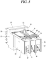
FIG. 5 is a perspective view of a molded case circuit breaker in accordance with an embodiment of the present disclosure in which an insulating cover is coupled to the molded case circuit breaker. -
FIG. 6 is a perspective view of an insulating cover applied to a molded case circuit breaker in accordance with an embodiment of the present disclosure. -
FIG. 7 is a bottom view ofFIG. 3 . -
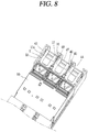
FIG. 8 is a bottom view ofFIG. 5 . -
FIG. 9 is a perspective view of an external connection device connected to a molded case circuit breaker in accordance with an embodiment of the present disclosure. -
FIG. 10 is a perspective view of an insulating cover applied to a molded case circuit breaker in accordance with another embodiment of the present disclosure. - Hereinafter, preferred embodiments of the present invention will be described with reference to the accompanying drawings, so that a person skilled in the art can easily carry out the invention. It should be understood that the technical idea and scope of the present invention are not limited to those preferred embodiments.
- Referring to the accompanying drawings, description will be given in detail of a molded case circuit breaker in accordance with each embodiment of the present disclosure.
- The molded case circuit breaker having a load-
side terminal 13 connected with anexternal connection device 30 in accordance with one embodiment of the present disclosure includes aninsulating cover 40 coupled to anenclosure 10 of the molded case circuit breaker, and theinsulating cover 40 includes aninsulating wall 44 interposed between theenclosure 10 and theexternal connection device 30. - The
enclosure 10 of the molded case circuit breaker is constructed approximately into a boxed shape of a cube. The top of theenclosure 10 is equipped with ahandle 11 to operate the switching mechanism. Thehandle 11 may be rotated to the On-position, the Off-position, and the Reset-position. - The front part of the
enclosure 10 is provided with a power-side terminal 12 that may be connected to the power line, and the rear (right side of the drawing) is provided with a load-side terminal 13 that may be connected to the load. The upper surface of the power-side terminal 12 and the upper surface of the load-side terminal 13 form anassembly hole 14 so that the load may be assembled and monitored on the terminal side, respectively. - A contact part is provided inside the
enclosure 10. The contact part is provided with a fixed contact (not shown) and a movable contact (not shown) that may be contacted or separated by the action of the switching device including thehandle 11 to connect or disconnect the circuit. -
Multiple bus bars 20 are installed on a panel (not shown) of a distribution board. For three-phase circuits, thebus bars 20 may be installed in parallel. The main current flowing through thebus bars 20 will flow in the load through the molded case circuit breaker. - The load-
side terminal 13 of theenclosure 10 is secured to the panel of the distribution board by amounting bracket 23. - The load-
side terminal 13 is provided with aninter-phase partition wall 15. Theinter-phase partition wall 15 is provided with a recess along the direction of height at the end. The inner part of therecess 16 is provided with afixing part 17. The insulatingcover 40 is inserted into therecess 16 and the fixingpart 17 and secured therebetween. - The upper part of the
enclosure 10 is provided with anupper cover 19. In some cases, theenclosure 10 is referred to as a case, and the case and cover are collectively referred to as the enclosure. - The power-
side terminal 12 is provided with a connection member for connecting the power-side terminal (which may be integrated with the fixed contacts) extended from the fixed contact (not shown) to thebus bar 20. The connection member may consist of connectors (not shown) and finger assemblies (not shown). - As shown above, the molded case circuit breakers that may be connected to the bus bar are also called a plug-in molded case circuit breaker.
- A
base bus supporter 25 is provided to protect the connection member between the power-side terminal 12 and thebus bar 20 and maintain insulation with the outside. Thebase bus supporter 25 is formed of an insulating material. - The
base bus supporter 25 is fixed to the power-side terminal 12 so as to cover the connecting member. Thebase bus supporter 25 may be formed in the form of a box which is open at the rear as a whole. - An
entry part 26 is provided at the front of thebase bus supporter 25. Theentry part 26 may be formed in the form of multiple teeth from the side to allow fit between thebus bar 20. These teeth may be formed to be engaged in thebus bar 20. - An
upper support 27 is provided on the upper part of thebase bus supporter 25. Theupper support 27 has an accommodation space, and an inter-phase partition wall is provided in the accommodation space. - A mounting
bracket 23 is provided. The mountingbracket 23 is installed on the distribution board panel and secures theenclosure 10 of the molded case circuit breaker and theexternal connection device 30. - The
external connection device 30 is installed at the load-side terminal 13. Theexternal connection device 30 may be a power meter that measures the amount of power. - A
device terminal 31 of theexternal connection device 30 is exposed to the connectingbus bar 32 for each phase. The connectingbus bar 32 may be connected to aterminal 18 of the load-side terminal 13. - A
coupling part 33 protrudes between each phase of thedevice terminal 31 of theexternal connection device 30. An insulatingcover 40 is fitted to thecoupling part 33. - The insulating
cover 40 is provided to prevent insulation failure of the connectingbus bar 32, which is exposed to the space between the molded case circuit breaker and theexternal connection device 30. The insulatingcover 40 is fitted to theenclosure 10 of the molded case circuit breaker. The insulatingcover 40 is fitted in a downward direction from the top of theenclosure 10. - The insulating
cover 40 is provided with acover opening 41 so that thetop cover 19 of the molded case circuit breaker may be exposed. The user can operate thehandle 11 through thecover opening 41. - The top face of the insulating
cover 40 is constructed with amonitoring hole 42 to provide access to theassembly hole 14. Themonitoring hole 42 is formed on the front and rear sides respectively to connect to theassembly hole 14 on the power-side terminal 12 and theassembly hole 14 on the load-side terminal 13. Users can visually determine the assembly status of the terminal through themonitoring hole 42 and theassembly hole 14. In addition, the user can check the temperature status of the terminal through themonitoring hole 42 and theassembly hole 14 using equipment such as a thermometer or a thermal infrared camera. - The insulating
cover 40 is provided withsidewall 43 on the side of the rear. Thesidewall 43 covers theside 13a of the load-side terminal 13. It is desirable that thesidewall 43 is formed in such a size that it covers theside 13a of the load-side terminal 13. In other words, it is desirable for thesidewall 43 to form more than the width and height of the load-side terminal. As a result, insulation is improved. - The
sidewall 43 has a specified gap from theside 13a of the load-side terminal 13 (seeFIGS. 7 and8 ). Accordingly, an outlet passage (E) is provided for the leakage of gas or foreign substances from the arc or electric spark that occurs at the load-side terminal 13 or the connectingbus bar 32. - The insulating
wall 44 is provided at the rear of the insulatingcover 40. The insulatingwall 44 is disposed between theenclosure 10 and theexternal connection device 30 to improve insulation. - A gap (C) of a certain distance occurs between the load-
side terminal 13 and the insulating wall 44 (seeFIGS. 7 and8 ). This gap serves as a gas outlet and also maintains the distance between the molded case circuit breaker and theexternal connection device 30. - The insulating
wall 44 has a protrudingpartition wall 45 that is inserted into arecess 16 of aninter-phase partition wall 15 of the load-side terminal 13. Thepartition wall 45 is prepared and extended to theinter-phase partition wall 15 of the load-side terminal 13. Accordingly, the connectingbus bar 32 of theexternal connection device 30 is closed to the space surrounded by thepartition wall 45 and the insulatingwall 44 for each phase. - At the end of the
partition wall 45, aprotrusion 46 is formed, which is fitted into the fixingpart 17 of theinter-phase partition wall 15. Theprotrusion 46 may be formed in the form of a circular or polygon. Theprotrusion 46 is formed thicker than the thickness of thepartition wall 45. The insulatingcover 40 may only be fitted or removed in the upper and lower directions, without detaching forward or backward by means of theprotrusion 46. - On the insulating
wall 44, aterminal opening 47 is formed so that the terminal 18 of the load-side terminal 13 may be exposed. Theterminal opening 47 is prepared for each phase. Theterminal opening 47 may be formed by grooves that has a certain width and height from the bottom of the insulatingwall 44. - Where the insulating
wall 44 and thepartition wall 45 are in contact, aninsertion part 48 is formed that allows thecoupling part 33 protruding to the front of theexternal connection device 30 to be inserted. Thecoupling part 33 of theexternal connection device 30 and theinsertion part 48 of the insulatingcover 40 are inserted and the insulatingcover 40 is also fixed with theexternal connection device 30. - The front of the insulating
cover 40 protrudes afront cover 49 covering theupper support 27 of thebase bus supporter 25 which is fitted to the front of theenclosure 10. Thefront cover 49 may be of the shape and size covered by the coupling of a part of theupper support 27 of thebase bus supporter 25. - The insulating
cover 40 is constructed from the upper support of thebase bus supporter 25 equipped on the front of the molded case circuit breaker to theexternal connection device 30 located on the rear of the molded case circuit breaker, and installed stably, preventing the connectingbus bar 32 of theexternal connection device 30 from being exposed to damage to insulation. - The insulating
cover 40 includes sidewalls 43, which refer to theside 13a of the load-side terminal of the molded case circuit breaker, which improves insulation performance. - The insulating
cover 40 creates a gap (E,C) between theside 13a and the rear of the load-side terminal 13, thus inducing the discharge of arc gas or debris. -
FIG. 10 is a perspective view of an insulating cover applied to a molded case circuit breaker in accordance with another embodiment of the present disclosure. - For this insulating
cover 40A, the same reference number is used for the same part as the previous embodiments. - In this embodiment, the insulating
cover 40A is provided with a slidingdoor 50 on theterminal opening 47. The insulatingwall 44 is constructed with adoor groove 44a along the length direction, and thedoor groove 44a is fitted with the slidingdoor 50. Thedoor 50 is placed in a position lowered by the self-weight when no external force is applied. When the insulatingcover 40A is fitted to the molded case circuit breaker, thedoor 50 may be raised by the connectingbus bar 32. As a result, the insulatingwall 44 has the effect to be extended to the area tangent to the connectingbus bar 32. This means that insulation performance for the space between the molded case circuit breaker and theexternal connection device 30 is further improved. - While the invention has been shown and described with reference to the foregoing preferred embodiments thereof, it will be understood by those skilled in the art that various changes and modifications may be made without departing from the spirit and scope of the invention as defined by the appended claims. Therefore, the embodiments disclosed in the present disclosure are not intended to limit the scope of the present disclosure but are merely illustrative, and it should be understood that the scope of the technical idea of the present disclosure is not limited by those embodiments. That is, the scope of protection of the present invention should be construed according to the appended claims, and all technical ideas within the scope of equivalents thereof should be construed as being included in the scope of the present invention.
Claims (9)
- A molded case circuit breaker in which a load-side terminal 13 is connected to an external connection device 30, characterized by comprising:
an insulating cover 40 coupled to an enclosure 10 of the molded case circuit breaker, in which the insulating cover 40 includes an insulating wall 44 interposed between the enclosure 10 and the external connection device 30. - The molded case circuit breaker of claim 1, wherein the insulating cover 40 includes side walls 43 covering a side of the load-side terminal 13.
- The molded case circuit breaker of claim 1, wherein the insulating wall 44 includes a partition wall 45 formed at an inner portion of the insulating wall 44 to protrude and inserted into a recess formed on an inter-phase partition wall 15 of the load-side terminal 13.
- The molded case circuit breaker of claim 3, wherein the partition wall 45 includes a protrusion 46 formed on an end portion thereof and coupled by fitting to a fixing part formed at an end of a recess of an inter-phase partition wall 15.
- The molded case circuit breaker of claim 1, wherein the insulating partition wall 45 includes an opening 47 through which a terminal of the load-side terminal 13 is exposed.
- The molded case circuit breaker of claim 3 or 4, wherein an insertion part is formed on a contact portion between the insulating wall 44 and the partition wall 45, through which a coupling part formed to protrude on a front face of the external connection device 30 is inserted.
- The molded case circuit breaker of claim 1, wherein a monitoring hole is formed on the upper face of the insulating cover 40 to identify the internal condition of the load-side terminal 13.
- The molded case circuit breaker of claim 7, wherein a cover opening 41 is formed on the upper part of the enclosure 10, through which the upper cover equipped at the upper part of the enclosure 10 is exposed.
- The molded case circuit breaker of claim 1, wherein a protruding front cover 49 covering the upper support of a base bus supporter 25 coupled to the front of the enclosure 10 is formed on the front of the insulating cover 40.
Applications Claiming Priority (1)
| Application Number | Priority Date | Filing Date | Title |
|---|---|---|---|
| KR1020180159412A KR102102884B1 (en) | 2018-12-11 | 2018-12-11 | Molded Case Circuit Breaker |
Publications (2)
| Publication Number | Publication Date |
|---|---|
| EP3667690A1 true EP3667690A1 (en) | 2020-06-17 |
| EP3667690B1 EP3667690B1 (en) | 2025-05-14 |
Family
ID=68066682
Family Applications (1)
| Application Number | Title | Priority Date | Filing Date |
|---|---|---|---|
| EP19199335.1A Active EP3667690B1 (en) | 2018-12-11 | 2019-09-24 | Molded case circuit breaker |
Country Status (5)
| Country | Link |
|---|---|
| US (1) | US20200185177A1 (en) |
| EP (1) | EP3667690B1 (en) |
| JP (1) | JP6942770B2 (en) |
| KR (1) | KR102102884B1 (en) |
| CN (1) | CN111312559B (en) |
Families Citing this family (7)
| Publication number | Priority date | Publication date | Assignee | Title |
|---|---|---|---|---|
| US10164387B2 (en) * | 2015-02-09 | 2018-12-25 | Abb Schweiz Ag | Electrical device, electrical distribution system, and methods of assembling same |
| USD884657S1 (en) * | 2018-04-18 | 2020-05-19 | Abb S.P.A. | Circuit breaker |
| KR102573098B1 (en) * | 2020-05-04 | 2023-08-31 | 엘에스일렉트릭(주) | Solid State Circuit Breaker |
| USD997889S1 (en) * | 2020-07-10 | 2023-09-05 | Schneider Electric USA, Inc. | Switching device |
| CN112435887B (en) * | 2020-12-12 | 2025-02-25 | 西安亚能电气有限责任公司 | Signal remote transmission gas relay based on heavy gas action recognition |
| KR102266313B1 (en) * | 2021-03-05 | 2021-06-18 | 주식회사 월드인텍 | Monitoring system for over-voltage protection and temperature overload of branch circuit |
| KR102882098B1 (en) * | 2024-01-02 | 2025-11-07 | 엘에스일렉트릭(주) | Molded Case Circuit Breaker Having Exhaustion Unit |
Citations (5)
| Publication number | Priority date | Publication date | Assignee | Title |
|---|---|---|---|---|
| DE29505046U1 (en) * | 1995-03-24 | 1996-07-18 | Klöckner-Moeller GmbH, 53115 Bonn | Low-voltage switchgear with touch protection |
| EP1376638A1 (en) * | 2002-06-25 | 2004-01-02 | Schneider Electric Industries SAS | Electromagnetic protection and control assembly |
| US20050280973A1 (en) * | 2004-05-19 | 2005-12-22 | Fuji Electric Fa Components & Systems Co., Ltd. | Circuit breaker and terminal cover |
| US20140151201A1 (en) * | 2012-12-05 | 2014-06-05 | Eaton Corporation | Circuit breaker terminal shield with position indicator |
| WO2016176204A1 (en) * | 2015-04-27 | 2016-11-03 | Abb Technology Ag | Modular electrical devices and methods for assembling and mounting the same |
Family Cites Families (12)
| Publication number | Priority date | Publication date | Assignee | Title |
|---|---|---|---|---|
| JPS59105752U (en) * | 1982-12-29 | 1984-07-16 | 松下電工株式会社 | Breaker mounting bracket |
| GB2183400B (en) * | 1985-11-25 | 1989-11-01 | Matsushita Electric Works Ltd | A timer controlled multipole circuit breaker |
| JP2605620Y2 (en) * | 1993-05-20 | 2000-07-31 | 日東工業株式会社 | Breaker with terminal block |
| JPH087741A (en) * | 1994-06-20 | 1996-01-12 | Fuji Electric Co Ltd | Terminal cover for electrical equipment |
| JP3414243B2 (en) * | 1997-08-20 | 2003-06-09 | 松下電工株式会社 | Connection conversion adapter |
| US6356175B1 (en) * | 1999-08-30 | 2002-03-12 | Eaton Corporation | Circuit interrupter with improved terminal shield and shield cover |
| JP4407078B2 (en) * | 2001-04-27 | 2010-02-03 | 富士電機機器制御株式会社 | Circuit breaker terminal cover |
| JP4104996B2 (en) * | 2003-01-22 | 2008-06-18 | 三菱電機株式会社 | Breaker |
| KR200392657Y1 (en) * | 2005-05-11 | 2005-08-17 | 엘에스산전 주식회사 | Circuit Braker |
| JP2010251035A (en) * | 2009-04-14 | 2010-11-04 | Fuji Electric Fa Components & Systems Co Ltd | Circuit breaker |
| US9548170B2 (en) * | 2015-01-19 | 2017-01-17 | Eaton Corporation | Electrical switching apparatus with terminal guard assembly |
| US9905387B2 (en) * | 2016-03-28 | 2018-02-27 | General Electric Company | Circuit breaker including end covers |
-
2018
- 2018-12-11 KR KR1020180159412A patent/KR102102884B1/en active Active
-
2019
- 2019-09-24 EP EP19199335.1A patent/EP3667690B1/en active Active
- 2019-09-26 JP JP2019175906A patent/JP6942770B2/en active Active
- 2019-09-27 US US16/585,925 patent/US20200185177A1/en not_active Abandoned
- 2019-09-27 CN CN201910927296.4A patent/CN111312559B/en active Active
Patent Citations (5)
| Publication number | Priority date | Publication date | Assignee | Title |
|---|---|---|---|---|
| DE29505046U1 (en) * | 1995-03-24 | 1996-07-18 | Klöckner-Moeller GmbH, 53115 Bonn | Low-voltage switchgear with touch protection |
| EP1376638A1 (en) * | 2002-06-25 | 2004-01-02 | Schneider Electric Industries SAS | Electromagnetic protection and control assembly |
| US20050280973A1 (en) * | 2004-05-19 | 2005-12-22 | Fuji Electric Fa Components & Systems Co., Ltd. | Circuit breaker and terminal cover |
| US20140151201A1 (en) * | 2012-12-05 | 2014-06-05 | Eaton Corporation | Circuit breaker terminal shield with position indicator |
| WO2016176204A1 (en) * | 2015-04-27 | 2016-11-03 | Abb Technology Ag | Modular electrical devices and methods for assembling and mounting the same |
Also Published As
| Publication number | Publication date |
|---|---|
| EP3667690B1 (en) | 2025-05-14 |
| JP6942770B2 (en) | 2021-09-29 |
| JP2020095940A (en) | 2020-06-18 |
| CN111312559B (en) | 2022-07-05 |
| US20200185177A1 (en) | 2020-06-11 |
| KR102102884B1 (en) | 2020-04-22 |
| CN111312559A (en) | 2020-06-19 |
Similar Documents
| Publication | Publication Date | Title |
|---|---|---|
| EP3667690B1 (en) | Molded case circuit breaker | |
| JP6454036B2 (en) | DC circuit breaker | |
| EP2393095B1 (en) | Mold cased circuit breaker | |
| KR101853859B1 (en) | Structure of Terminal of Molded Case Circuit Breaker | |
| JP5844872B2 (en) | Circuit breaker for wiring | |
| CN110875164B (en) | Circuit breaker for wiring | |
| CN106935452B (en) | Electrical protection device of standardized specification | |
| CN111697478B (en) | Arc discharge system for a distribution box | |
| KR101994444B1 (en) | Circuit Breaker for DC | |
| CN112309783B (en) | Door phase separation device in molded case circuit breaker | |
| KR200487464Y1 (en) | Molded Case Circuit Breaker | |
| KR20180079048A (en) | Molded Case Circuit Breaker for DC | |
| CN116848611A (en) | Insulating material housing and compact circuit protective switch | |
| JP7019095B2 (en) | Connection conversion adapter and electrical equipment | |
| KR100364825B1 (en) | The Arc gas drafter in circuit breaker | |
| KR20060063418A (en) | Wiring breaker with strain suppression | |
| JP4696665B2 (en) | Earth leakage breaker | |
| CN220753245U (en) | Static contact assembly of switch | |
| EP3751590B1 (en) | Electronic trip device for molded case circuit breaker | |
| KR102648597B1 (en) | Arc Ventilation System of Distrbuting Board | |
| KR101364633B1 (en) | Insulating device for circuit breaker | |
| KR200496737Y1 (en) | Trip Device of Molded Case Circuit Breaker | |
| KR101252409B1 (en) | Base assembly having a heater combination portion and circuit breaker for electric wiring having the same | |
| JP2023094823A (en) | circuit breaker | |
| CN116997104A (en) | Modular insulating material housing and multi-pole modular series installation |
Legal Events
| Date | Code | Title | Description |
|---|---|---|---|
| PUAI | Public reference made under article 153(3) epc to a published international application that has entered the european phase |
Free format text: ORIGINAL CODE: 0009012 |
|
| STAA | Information on the status of an ep patent application or granted ep patent |
Free format text: STATUS: THE APPLICATION HAS BEEN PUBLISHED |
|
| AK | Designated contracting states |
Kind code of ref document: A1 Designated state(s): AL AT BE BG CH CY CZ DE DK EE ES FI FR GB GR HR HU IE IS IT LI LT LU LV MC MK MT NL NO PL PT RO RS SE SI SK SM TR |
|
| AX | Request for extension of the european patent |
Extension state: BA ME |
|
| STAA | Information on the status of an ep patent application or granted ep patent |
Free format text: STATUS: REQUEST FOR EXAMINATION WAS MADE |
|
| 17P | Request for examination filed |
Effective date: 20201217 |
|
| RBV | Designated contracting states (corrected) |
Designated state(s): AL AT BE BG CH CY CZ DE DK EE ES FI FR GB GR HR HU IE IS IT LI LT LU LV MC MK MT NL NO PL PT RO RS SE SI SK SM TR |
|
| STAA | Information on the status of an ep patent application or granted ep patent |
Free format text: STATUS: EXAMINATION IS IN PROGRESS |
|
| 17Q | First examination report despatched |
Effective date: 20211117 |
|
| GRAP | Despatch of communication of intention to grant a patent |
Free format text: ORIGINAL CODE: EPIDOSNIGR1 |
|
| STAA | Information on the status of an ep patent application or granted ep patent |
Free format text: STATUS: GRANT OF PATENT IS INTENDED |
|
| INTG | Intention to grant announced |
Effective date: 20241219 |
|
| GRAS | Grant fee paid |
Free format text: ORIGINAL CODE: EPIDOSNIGR3 |
|
| GRAA | (expected) grant |
Free format text: ORIGINAL CODE: 0009210 |
|
| STAA | Information on the status of an ep patent application or granted ep patent |
Free format text: STATUS: THE PATENT HAS BEEN GRANTED |
|
| P01 | Opt-out of the competence of the unified patent court (upc) registered |
Free format text: CASE NUMBER: APP_14687/2025 Effective date: 20250326 |
|
| AK | Designated contracting states |
Kind code of ref document: B1 Designated state(s): AL AT BE BG CH CY CZ DE DK EE ES FI FR GB GR HR HU IE IS IT LI LT LU LV MC MK MT NL NO PL PT RO RS SE SI SK SM TR |
|
| REG | Reference to a national code |
Ref country code: GB Ref legal event code: FG4D |
|
| REG | Reference to a national code |
Ref country code: CH Ref legal event code: EP |
|
| REG | Reference to a national code |
Ref country code: DE Ref legal event code: R096 Ref document number: 602019069896 Country of ref document: DE |
|
| REG | Reference to a national code |
Ref country code: IE Ref legal event code: FG4D |
|
| REG | Reference to a national code |
Ref country code: NL Ref legal event code: MP Effective date: 20250514 |
|
| PG25 | Lapsed in a contracting state [announced via postgrant information from national office to epo] |
Ref country code: PT Free format text: LAPSE BECAUSE OF FAILURE TO SUBMIT A TRANSLATION OF THE DESCRIPTION OR TO PAY THE FEE WITHIN THE PRESCRIBED TIME-LIMIT Effective date: 20250915 Ref country code: FI Free format text: LAPSE BECAUSE OF FAILURE TO SUBMIT A TRANSLATION OF THE DESCRIPTION OR TO PAY THE FEE WITHIN THE PRESCRIBED TIME-LIMIT Effective date: 20250514 Ref country code: ES Free format text: LAPSE BECAUSE OF FAILURE TO SUBMIT A TRANSLATION OF THE DESCRIPTION OR TO PAY THE FEE WITHIN THE PRESCRIBED TIME-LIMIT Effective date: 20250514 |
|
| PGFP | Annual fee paid to national office [announced via postgrant information from national office to epo] |
Ref country code: DE Payment date: 20250603 Year of fee payment: 7 |
|
| REG | Reference to a national code |
Ref country code: LT Ref legal event code: MG9D |
|
| PG25 | Lapsed in a contracting state [announced via postgrant information from national office to epo] |
Ref country code: NO Free format text: LAPSE BECAUSE OF FAILURE TO SUBMIT A TRANSLATION OF THE DESCRIPTION OR TO PAY THE FEE WITHIN THE PRESCRIBED TIME-LIMIT Effective date: 20250814 Ref country code: GR Free format text: LAPSE BECAUSE OF FAILURE TO SUBMIT A TRANSLATION OF THE DESCRIPTION OR TO PAY THE FEE WITHIN THE PRESCRIBED TIME-LIMIT Effective date: 20250815 |
|
| PG25 | Lapsed in a contracting state [announced via postgrant information from national office to epo] |
Ref country code: NL Free format text: LAPSE BECAUSE OF FAILURE TO SUBMIT A TRANSLATION OF THE DESCRIPTION OR TO PAY THE FEE WITHIN THE PRESCRIBED TIME-LIMIT Effective date: 20250514 Ref country code: PL Free format text: LAPSE BECAUSE OF FAILURE TO SUBMIT A TRANSLATION OF THE DESCRIPTION OR TO PAY THE FEE WITHIN THE PRESCRIBED TIME-LIMIT Effective date: 20250514 |
|
| REG | Reference to a national code |
Ref country code: AT Ref legal event code: MK05 Ref document number: 1795552 Country of ref document: AT Kind code of ref document: T Effective date: 20250514 |
|
| PG25 | Lapsed in a contracting state [announced via postgrant information from national office to epo] |
Ref country code: BG Free format text: LAPSE BECAUSE OF FAILURE TO SUBMIT A TRANSLATION OF THE DESCRIPTION OR TO PAY THE FEE WITHIN THE PRESCRIBED TIME-LIMIT Effective date: 20250514 |
|
| PG25 | Lapsed in a contracting state [announced via postgrant information from national office to epo] |
Ref country code: HR Free format text: LAPSE BECAUSE OF FAILURE TO SUBMIT A TRANSLATION OF THE DESCRIPTION OR TO PAY THE FEE WITHIN THE PRESCRIBED TIME-LIMIT Effective date: 20250514 |
|
| PG25 | Lapsed in a contracting state [announced via postgrant information from national office to epo] |
Ref country code: AT Free format text: LAPSE BECAUSE OF FAILURE TO SUBMIT A TRANSLATION OF THE DESCRIPTION OR TO PAY THE FEE WITHIN THE PRESCRIBED TIME-LIMIT Effective date: 20250514 |
|
| PG25 | Lapsed in a contracting state [announced via postgrant information from national office to epo] |
Ref country code: RS Free format text: LAPSE BECAUSE OF FAILURE TO SUBMIT A TRANSLATION OF THE DESCRIPTION OR TO PAY THE FEE WITHIN THE PRESCRIBED TIME-LIMIT Effective date: 20250814 |
|
| PG25 | Lapsed in a contracting state [announced via postgrant information from national office to epo] |
Ref country code: IS Free format text: LAPSE BECAUSE OF FAILURE TO SUBMIT A TRANSLATION OF THE DESCRIPTION OR TO PAY THE FEE WITHIN THE PRESCRIBED TIME-LIMIT Effective date: 20250914 |
|
| PG25 | Lapsed in a contracting state [announced via postgrant information from national office to epo] |
Ref country code: LV Free format text: LAPSE BECAUSE OF FAILURE TO SUBMIT A TRANSLATION OF THE DESCRIPTION OR TO PAY THE FEE WITHIN THE PRESCRIBED TIME-LIMIT Effective date: 20250514 |
|
| PG25 | Lapsed in a contracting state [announced via postgrant information from national office to epo] |
Ref country code: DK Free format text: LAPSE BECAUSE OF FAILURE TO SUBMIT A TRANSLATION OF THE DESCRIPTION OR TO PAY THE FEE WITHIN THE PRESCRIBED TIME-LIMIT Effective date: 20250514 Ref country code: SM Free format text: LAPSE BECAUSE OF FAILURE TO SUBMIT A TRANSLATION OF THE DESCRIPTION OR TO PAY THE FEE WITHIN THE PRESCRIBED TIME-LIMIT Effective date: 20250514 |
|
| PG25 | Lapsed in a contracting state [announced via postgrant information from national office to epo] |
Ref country code: CZ Free format text: LAPSE BECAUSE OF FAILURE TO SUBMIT A TRANSLATION OF THE DESCRIPTION OR TO PAY THE FEE WITHIN THE PRESCRIBED TIME-LIMIT Effective date: 20250514 |
|
| PG25 | Lapsed in a contracting state [announced via postgrant information from national office to epo] |
Ref country code: EE Free format text: LAPSE BECAUSE OF FAILURE TO SUBMIT A TRANSLATION OF THE DESCRIPTION OR TO PAY THE FEE WITHIN THE PRESCRIBED TIME-LIMIT Effective date: 20250514 |
|
| PG25 | Lapsed in a contracting state [announced via postgrant information from national office to epo] |
Ref country code: RO Free format text: LAPSE BECAUSE OF FAILURE TO SUBMIT A TRANSLATION OF THE DESCRIPTION OR TO PAY THE FEE WITHIN THE PRESCRIBED TIME-LIMIT Effective date: 20250514 Ref country code: SK Free format text: LAPSE BECAUSE OF FAILURE TO SUBMIT A TRANSLATION OF THE DESCRIPTION OR TO PAY THE FEE WITHIN THE PRESCRIBED TIME-LIMIT Effective date: 20250514 |
|
| PG25 | Lapsed in a contracting state [announced via postgrant information from national office to epo] |
Ref country code: IT Free format text: LAPSE BECAUSE OF FAILURE TO SUBMIT A TRANSLATION OF THE DESCRIPTION OR TO PAY THE FEE WITHIN THE PRESCRIBED TIME-LIMIT Effective date: 20250514 |
|
| REG | Reference to a national code |
Ref country code: DE Ref legal event code: R097 Ref document number: 602019069896 Country of ref document: DE |
|
| PLBE | No opposition filed within time limit |
Free format text: ORIGINAL CODE: 0009261 |
|
| STAA | Information on the status of an ep patent application or granted ep patent |
Free format text: STATUS: NO OPPOSITION FILED WITHIN TIME LIMIT |
|
| REG | Reference to a national code |
Ref country code: CH Ref legal event code: L10 Free format text: ST27 STATUS EVENT CODE: U-0-0-L10-L00 (AS PROVIDED BY THE NATIONAL OFFICE) Effective date: 20260325 |
|
| 26N | No opposition filed |
Effective date: 20260217 |
|
| REG | Reference to a national code |
Ref country code: CH Ref legal event code: H13 Free format text: ST27 STATUS EVENT CODE: U-0-0-H10-H13 (AS PROVIDED BY THE NATIONAL OFFICE) Effective date: 20260504 |