EP3667299B1 - Système d'imagerie multimodal - Google Patents
Système d'imagerie multimodal Download PDFInfo
- Publication number
- EP3667299B1 EP3667299B1 EP19211603.6A EP19211603A EP3667299B1 EP 3667299 B1 EP3667299 B1 EP 3667299B1 EP 19211603 A EP19211603 A EP 19211603A EP 3667299 B1 EP3667299 B1 EP 3667299B1
- Authority
- EP
- European Patent Office
- Prior art keywords
- light
- filter element
- light spectrum
- filter
- image sensor
- Prior art date
- Legal status (The legal status is an assumption and is not a legal conclusion. Google has not performed a legal analysis and makes no representation as to the accuracy of the status listed.)
- Active
Links
- 238000003384 imaging method Methods 0.000 title claims description 102
- 238000001228 spectrum Methods 0.000 claims description 125
- 230000003287 optical effect Effects 0.000 claims description 27
- 238000000034 method Methods 0.000 claims description 25
- 230000003595 spectral effect Effects 0.000 claims description 22
- 230000005540 biological transmission Effects 0.000 claims description 18
- 230000004907 flux Effects 0.000 claims description 18
- 230000001427 coherent effect Effects 0.000 claims description 6
- 238000001208 nuclear magnetic resonance pulse sequence Methods 0.000 claims description 6
- 230000008033 biological extinction Effects 0.000 claims description 5
- 239000012620 biological material Substances 0.000 claims description 4
- 238000000799 fluorescence microscopy Methods 0.000 claims description 4
- 241000237519 Bivalvia Species 0.000 claims 1
- 235000020639 clam Nutrition 0.000 claims 1
- 239000000523 sample Substances 0.000 description 20
- 230000008569 process Effects 0.000 description 10
- 238000013459 approach Methods 0.000 description 9
- 230000008901 benefit Effects 0.000 description 9
- 239000000463 material Substances 0.000 description 9
- 238000001093 holography Methods 0.000 description 8
- 210000004027 cell Anatomy 0.000 description 6
- 239000000835 fiber Substances 0.000 description 5
- 230000007246 mechanism Effects 0.000 description 5
- 238000000926 separation method Methods 0.000 description 5
- 230000000903 blocking effect Effects 0.000 description 4
- 238000001514 detection method Methods 0.000 description 4
- 238000001914 filtration Methods 0.000 description 4
- 238000012538 light obscuration Methods 0.000 description 4
- 239000002245 particle Substances 0.000 description 4
- 238000005424 photoluminescence Methods 0.000 description 4
- 230000005855 radiation Effects 0.000 description 4
- 239000010409 thin film Substances 0.000 description 4
- 238000013461 design Methods 0.000 description 3
- 230000009977 dual effect Effects 0.000 description 3
- 238000005286 illumination Methods 0.000 description 3
- 238000000386 microscopy Methods 0.000 description 3
- 238000012545 processing Methods 0.000 description 3
- 238000001069 Raman spectroscopy Methods 0.000 description 2
- 238000010521 absorption reaction Methods 0.000 description 2
- 238000010168 coupling process Methods 0.000 description 2
- 238000005859 coupling reaction Methods 0.000 description 2
- 230000000694 effects Effects 0.000 description 2
- 238000005516 engineering process Methods 0.000 description 2
- 239000012530 fluid Substances 0.000 description 2
- 230000006872 improvement Effects 0.000 description 2
- 238000011835 investigation Methods 0.000 description 2
- 238000004519 manufacturing process Methods 0.000 description 2
- 239000003550 marker Substances 0.000 description 2
- 238000000059 patterning Methods 0.000 description 2
- 230000004044 response Effects 0.000 description 2
- 239000004065 semiconductor Substances 0.000 description 2
- 238000000411 transmission spectrum Methods 0.000 description 2
- 238000003332 Raman imaging Methods 0.000 description 1
- 238000002835 absorbance Methods 0.000 description 1
- 238000004458 analytical method Methods 0.000 description 1
- 230000002238 attenuated effect Effects 0.000 description 1
- 239000012472 biological sample Substances 0.000 description 1
- 210000004369 blood Anatomy 0.000 description 1
- 239000008280 blood Substances 0.000 description 1
- 210000000601 blood cell Anatomy 0.000 description 1
- 230000015556 catabolic process Effects 0.000 description 1
- 230000008859 change Effects 0.000 description 1
- 238000004891 communication Methods 0.000 description 1
- 239000002131 composite material Substances 0.000 description 1
- 238000010276 construction Methods 0.000 description 1
- 238000004163 cytometry Methods 0.000 description 1
- 230000007547 defect Effects 0.000 description 1
- 230000001419 dependent effect Effects 0.000 description 1
- 230000004069 differentiation Effects 0.000 description 1
- 230000005670 electromagnetic radiation Effects 0.000 description 1
- 230000005284 excitation Effects 0.000 description 1
- 238000002073 fluorescence micrograph Methods 0.000 description 1
- 238000012632 fluorescent imaging Methods 0.000 description 1
- 238000000338 in vitro Methods 0.000 description 1
- 150000002605 large molecules Chemical class 0.000 description 1
- 238000004020 luminiscence type Methods 0.000 description 1
- 229920002521 macromolecule Polymers 0.000 description 1
- 230000002906 microbiologic effect Effects 0.000 description 1
- 244000005700 microbiome Species 0.000 description 1
- 239000000203 mixture Substances 0.000 description 1
- 238000012544 monitoring process Methods 0.000 description 1
- 230000000877 morphologic effect Effects 0.000 description 1
- 238000012634 optical imaging Methods 0.000 description 1
- 230000003252 repetitive effect Effects 0.000 description 1
- 238000001338 self-assembly Methods 0.000 description 1
- 238000010561 standard procedure Methods 0.000 description 1
- 230000003068 static effect Effects 0.000 description 1
- 230000004936 stimulating effect Effects 0.000 description 1
- 239000000758 substrate Substances 0.000 description 1
- 210000001519 tissue Anatomy 0.000 description 1
- 238000002834 transmittance Methods 0.000 description 1
- 238000001429 visible spectrum Methods 0.000 description 1
Images


Classifications
-
- G—PHYSICS
- G01—MEASURING; TESTING
- G01N—INVESTIGATING OR ANALYSING MATERIALS BY DETERMINING THEIR CHEMICAL OR PHYSICAL PROPERTIES
- G01N21/00—Investigating or analysing materials by the use of optical means, i.e. using sub-millimetre waves, infrared, visible or ultraviolet light
- G01N21/17—Systems in which incident light is modified in accordance with the properties of the material investigated
- G01N21/21—Polarisation-affecting properties
-
- G—PHYSICS
- G01—MEASURING; TESTING
- G01N—INVESTIGATING OR ANALYSING MATERIALS BY DETERMINING THEIR CHEMICAL OR PHYSICAL PROPERTIES
- G01N21/00—Investigating or analysing materials by the use of optical means, i.e. using sub-millimetre waves, infrared, visible or ultraviolet light
- G01N21/17—Systems in which incident light is modified in accordance with the properties of the material investigated
- G01N21/25—Colour; Spectral properties, i.e. comparison of effect of material on the light at two or more different wavelengths or wavelength bands
- G01N21/31—Investigating relative effect of material at wavelengths characteristic of specific elements or molecules, e.g. atomic absorption spectrometry
-
- G—PHYSICS
- G01—MEASURING; TESTING
- G01N—INVESTIGATING OR ANALYSING MATERIALS BY DETERMINING THEIR CHEMICAL OR PHYSICAL PROPERTIES
- G01N21/00—Investigating or analysing materials by the use of optical means, i.e. using sub-millimetre waves, infrared, visible or ultraviolet light
- G01N21/17—Systems in which incident light is modified in accordance with the properties of the material investigated
- G01N21/25—Colour; Spectral properties, i.e. comparison of effect of material on the light at two or more different wavelengths or wavelength bands
- G01N21/255—Details, e.g. use of specially adapted sources, lighting or optical systems
-
- G—PHYSICS
- G02—OPTICS
- G02B—OPTICAL ELEMENTS, SYSTEMS OR APPARATUS
- G02B21/00—Microscopes
- G02B21/16—Microscopes adapted for ultraviolet illumination ; Fluorescence microscopes
-
- G—PHYSICS
- G02—OPTICS
- G02B—OPTICAL ELEMENTS, SYSTEMS OR APPARATUS
- G02B21/00—Microscopes
- G02B21/36—Microscopes arranged for photographic purposes or projection purposes or digital imaging or video purposes including associated control and data processing arrangements
- G02B21/361—Optical details, e.g. image relay to the camera or image sensor
-
- G—PHYSICS
- G06—COMPUTING; CALCULATING OR COUNTING
- G06T—IMAGE DATA PROCESSING OR GENERATION, IN GENERAL
- G06T7/00—Image analysis
- G06T7/0002—Inspection of images, e.g. flaw detection
- G06T7/0012—Biomedical image inspection
-
- H—ELECTRICITY
- H04—ELECTRIC COMMUNICATION TECHNIQUE
- H04N—PICTORIAL COMMUNICATION, e.g. TELEVISION
- H04N23/00—Cameras or camera modules comprising electronic image sensors; Control thereof
- H04N23/50—Constructional details
- H04N23/55—Optical parts specially adapted for electronic image sensors; Mounting thereof
-
- H—ELECTRICITY
- H04—ELECTRIC COMMUNICATION TECHNIQUE
- H04N—PICTORIAL COMMUNICATION, e.g. TELEVISION
- H04N23/00—Cameras or camera modules comprising electronic image sensors; Control thereof
- H04N23/56—Cameras or camera modules comprising electronic image sensors; Control thereof provided with illuminating means
-
- G—PHYSICS
- G01—MEASURING; TESTING
- G01N—INVESTIGATING OR ANALYSING MATERIALS BY DETERMINING THEIR CHEMICAL OR PHYSICAL PROPERTIES
- G01N21/00—Investigating or analysing materials by the use of optical means, i.e. using sub-millimetre waves, infrared, visible or ultraviolet light
- G01N21/17—Systems in which incident light is modified in accordance with the properties of the material investigated
- G01N2021/178—Methods for obtaining spatial resolution of the property being measured
-
- G—PHYSICS
- G01—MEASURING; TESTING
- G01N—INVESTIGATING OR ANALYSING MATERIALS BY DETERMINING THEIR CHEMICAL OR PHYSICAL PROPERTIES
- G01N21/00—Investigating or analysing materials by the use of optical means, i.e. using sub-millimetre waves, infrared, visible or ultraviolet light
- G01N21/62—Systems in which the material investigated is excited whereby it emits light or causes a change in wavelength of the incident light
- G01N21/63—Systems in which the material investigated is excited whereby it emits light or causes a change in wavelength of the incident light optically excited
- G01N21/64—Fluorescence; Phosphorescence
- G01N21/645—Specially adapted constructive features of fluorimeters
- G01N21/6456—Spatial resolved fluorescence measurements; Imaging
-
- G—PHYSICS
- G01—MEASURING; TESTING
- G01N—INVESTIGATING OR ANALYSING MATERIALS BY DETERMINING THEIR CHEMICAL OR PHYSICAL PROPERTIES
- G01N21/00—Investigating or analysing materials by the use of optical means, i.e. using sub-millimetre waves, infrared, visible or ultraviolet light
- G01N21/62—Systems in which the material investigated is excited whereby it emits light or causes a change in wavelength of the incident light
- G01N21/63—Systems in which the material investigated is excited whereby it emits light or causes a change in wavelength of the incident light optically excited
- G01N21/65—Raman scattering
-
- G—PHYSICS
- G06—COMPUTING; CALCULATING OR COUNTING
- G06T—IMAGE DATA PROCESSING OR GENERATION, IN GENERAL
- G06T2207/00—Indexing scheme for image analysis or image enhancement
- G06T2207/10—Image acquisition modality
- G06T2207/10056—Microscopic image
-
- G—PHYSICS
- G06—COMPUTING; CALCULATING OR COUNTING
- G06T—IMAGE DATA PROCESSING OR GENERATION, IN GENERAL
- G06T2207/00—Indexing scheme for image analysis or image enhancement
- G06T2207/10—Image acquisition modality
- G06T2207/10064—Fluorescence image
-
- G—PHYSICS
- G06—COMPUTING; CALCULATING OR COUNTING
- G06T—IMAGE DATA PROCESSING OR GENERATION, IN GENERAL
- G06T2207/00—Indexing scheme for image analysis or image enhancement
- G06T2207/10—Image acquisition modality
- G06T2207/10141—Special mode during image acquisition
- G06T2207/10152—Varying illumination
Definitions
- the present invention relates to a system and a method for the simultaneous capture of multiple images of different modalities.
- the present invention aims to address these issues.
- the investigation of biological material can benefit from the use of multiple imaging modalities.
- the use of multiple modalities can help to provide information on morphology, function and composition in a manner which offers improved detail over any single technique alone.
- US20160041094A1 discloses a lens-free imaging system suitable for in-vitro medical diagnostics with an emphasis on the detection of particles, e.g. blood cells.
- the approach they disclose includes imaging of a fluidic chamber either while fluid containing the particles is static or while it is flowing. With this approach they indicate that either shadow images or fluorescence images may be produced.
- US2012087645A1 relates to dual mode imaging systems, in particular visible light and infrared light imaging systems.
- the imaging system disclosed includes an image sensor and an optical filter.
- the image sensor captures image data in response to incident light.
- the optical filter filters the light and includes a dual window transmission spectrum.
- the dual window transmission spectrum includes a first transmission window having a first pass band aligned to pass visible light and a second transmission window having a second pass band overlapping with an absorption band of infrared light in Earth's atmosphere.
- US2010140504A1 relates to methods and apparatus for measuring fluorescence, in particularly for TIRF (Total Internal Reflection Fluorescence) microscopy.
- the method includes illuminating at least a portion of a sample surface with radiation for stimulating fluorescence. Intensity of the radiation varies with position and values indicative of the spatial intensity distribution of fluorescence emitted from said portion of the sample surface are measured. The measured values of fluorescence are modified to take account of the spatial variation in intensity of radiation incident upon the surface by utilising the measured profile.
- An objective of the present invention is to provide a multimodal imaging system which can capture different imaging modalities both simultaneously and individually.
- the multimodal imaging system is defined in appended claim 1.
- a first light source emits light which is at least partially polarised because it provides a light spectrum suitable for selective detection based upon its polarisation.
- the polarisation may be linear, circular, elliptical, or any other geometrical orientation or combination known in the art which generates a distinctive polarisation feature on which to base detection of the light spectrum.
- the second light spectrum may be unpolarised, or may be of a different polarisation or polarisation combination to the first light spectrum such that each light spectrum can be differentiated.
- the degree of polarisation of the first light spectrum is not equal to the degree of polarisation of the second light spectrum, where the degree of polarisation (DOP) is the proportion of the light which is polarised.
- DOP degree of polarisation
- the frequency components of light comprising the first light spectrum differ from the frequency components of light comprising the second light spectrum.
- the two light spectra may be separable by frequency domain criteria known in the art. While the first light spectrum and the second light spectrum are not identical, they may have some common frequency components while still being amenable to separation in the frequency domain, e.g. by low pass, high pass, band pass or band stop filtering techniques and combinations thereof.
- These spectral filtering techniques may be applied in ways known in the art, e.g. interference, absorptive or dichroic filters, and using implementations based on standard techniques such as multi-layer thin films.
- the light source may emit a pulsed light.
- the first light spectrum comprises a first pulse sequence and the second light spectrum comprises a second pulse sequence.
- the second pulse sequence may also comprise a single pulse, i.e. a continuous, or substantially continuous energy flux level Provided the first pulse sequence and the second pulse sequence are different, this approach has the advantage of providing easily separable light intensity within the time domain.
- the energy flux of light impinging on the image sensor from any filter element of the optical filter is within the dynamic range of the image sensor. This is particularly advantageous because different imaging modalities often result in different light intensities. Where these intensities vary significantly, the illuminance of light impinging on the image sensor exceeds the dynamic range of the sensor and thereby prevents the sensor from capturing the required image detail for all of the imaging modalities.
- At least the first filter element comprises a spectral filter component and a polarising filter component arranged in the same light path. It is advantageous to be able to utilise the polarising filter in combination with a polarising light source as a control and selection mechanism for light passing through the filter. When combined with a spectral filter it provides an additional separation and control mechanism.
- the second filter element also comprises a polarising filter component
- the polarising filter component of the first filter element has a lower Polarisation Extinction Ratio (PER) than the polarising filter component of the second filter element.
- PER Polarisation Extinction Ratio
- an advantageous embodiment of the polarising filter component comprises a wire-grid based polarising filter. This approach to the creation of polarising filters is easy to implement and can be achieved reliably and repeatably. It also provides means of fabrication which is compatible with image sensors .
- one of the imaging modes is holographic imaging.
- Digital holographic imaging offers both lateral and depth resolution resulting in 3-dimensional imaging with the ability to provide detail to the micron range which is advantageous for biological and microbiological application.
- the detailed structural information contained in holographic images can be especially helpful in the investigation of biological materials at the microscopic level.
- one of the imaging modes is fluorescence imaging.
- This imaging mode is widely used in biological applications, especially in fluorescence microscopy where it is used for many applications associated with the observation of living cells and organisms. It may, for example, be used to improve the differentiation of individual cells or identify specific features of cell types. Fluorescence is also difficult to combine with other imaging modalities because it provides much lower light emission characteristics than most.
- one of the imaging modes is photoluminescence imaging.
- This imaging mode is widely used in industrial applications, especially in microscopy where it is used for many applications associated with the observation of defects and functions of engineered materials such as semiconductor devices in combination with an external light stimuli. It may, for example, be used to localise faults in large areas during the processing of engineered materials for failure analysis and yield improvement purposes.
- Photoluminescence imaging is also difficult to combine with other imaging modalities because it provides much lower light emission characteristics than most.
- Embodiments may combine the above, or other imaging modalities at the microscopic or macroscopic scale. This is especially advantageous wherever disparities occur between light intensity (energy flux) levels of the resultant light spectra of the imaging modes. e.g. conventional photographic imaging and phosphorescence or photoluminescence.
- the multimodal imaging system comprises Raman imaging as one of the imaging modes.
- the multimodal imaging system is a lens-free multimodal imaging system. This is especially advantageous for microscopic applications. Conventional microscopes are bulky, expensive and difficult to scale. Lens-free microscopy offers a solution to these limitations because it is a simple and cost-effective alternative which can be implemented in a small form factor.
- the invention also relates to a multimodal imaging method as defined in appended claim 12.
- the energy flux of light impinging on the image sensor from each source, or any filter element of the optical filter is within the dynamic range of the image sensor.
- this allows for multiple high quality images from different imaging modalities to be captured simultaneously when multiple light sources impinge on different regions of an image sensor. It is also advantageous to be able to adjust or limit the range of energy flux in some embodiments to enable lower performance and lower cost imaging sensors to be used for advanced multimodal imaging application.
- the signal intensity levels may differ significantly between different imaging modes. This difference is often found to be at least an order of magnitude, with some modality mixes resulting in much greater disparity between the light intensities of different modes.
- the device may be applied to a method of multimodal imaging involving holography and fluorescent imaging in which case signal intensity levels may vary by five to seven orders of magnitude.
- Image sensors commonly available on the market do not have sufficient dynamic range to be able to cater for such a large variation in intensity of impinging light sources. They can work effectively only with a limited dynamic range of received energy flux, generally measured in decibels (dB).
- Standard CMOS image sensors only have a dynamic range of approximately 60dB, higher end image sensors may have 70dB or more, some high end image sensors have a dynamic range of over 80dB, but very few image sensors have a dynamic range much above 93dB. Consequently, it is an objective of the current invention to maintain the energy flux of light impinging on the image sensor from all imaging modes to be within the dynamic range of the image sensor.
- the maximum disparity between energy flux of the simultaneous imaging modes of any embodiments should preferably meet this criteria, and preferably be less than 65dB, or more preferably be less than 75 dB, or more preferably be less than 85 dB, or more preferably be less than 95 dB or more preferably still be less than 105 dB.
- An example multimodal imaging method comprises the steps of: a) illuminating a sample with a partially coherent polarised light comprising a first light spectrum and generating a second light spectrum, b) transmitting the first light spectrum and the second light spectrum through an optical filter comprising a first filter element and a second filter element arranged as an array parallel to an image sensor comprising a plurality of pixels, wherein the first light spectrum in transmitted and attenuated by the first filter element and the second light spectrum is transmitted by the second filter element, c) simultaneously capturing light transmitted by the first filter element with a first subset of imager pixels, and light transmitted by the second filter element with a second subset of imager pixels, wherein each pixel receives light via a single filter element.
- the sample may preferably be a biological sample, such as but not limited to cells, tissue, blood, or microorganisms.
- the sample may be a particle of biological, organic or inorganic nature.
- the sample may be transparent or partially transparent which is advantageous for in-line holography.
- the sample when excited by a first light spectrum, emits a second light spectrum.
- the second light spectrum is preferably generated by the process of fluorescence, but may also preferably be provided by other processes known in the art such as luminescence, phosphorescence, photoluminescence or Raman scattering, hence the second light spectrum preferably comprises light resulting from these processes.
- These processes are advantageous for the identification of features associated with a sample, and different processes provide for different imaging modalities.
- Example embodiments may use one or a plurality of modalities supported by one or a plurality of these processes, e.g. an example may use two different fluorescent markers for identifying different features in a sample, another example may use Raman scattering and fluorescence. Any practical combination of these processes may be used by the method.
- the frequency components of the first light spectrum differ from the frequency components of the second light spectrum. This advantageously allows for filtering and separation of the light spectra based on techniques known in the art, e.g. high pass, low pass, band pass filtering etc.
- the multimodal imaging method may additionally comprise the steps of, reading data from the first subset of imager pixels of the image sensor where light transmitted by the first filter element is captured to create a first image, and reading data from the second subset of imager pixels of the image sensor where light transmitted by the second filter element is captured to create a second image.
- This is advantageous for capturing multiple imaging modalities simultaneously which also allows for multiple modalities to be compared for the same image scene.
- information presented about the sample is greatly improved over separate consideration of the modalities where the scene may change.
- the images may be combined into a single image with little additional processing, thereby offering a true multimodal image of the same scene which offers further information about the sample.
- the light source 110 provides illumination for a scene to be imaged and emits partially coherent polarised light 160.
- the light may travel directly and/or indirectly (e.g. via reflection off a sample) to the optical filter 130.
- the optical filter 130 comprises a first filter element 131 and a second filter element 132 which are arranged as an array parallel to the image sensor 120.
- the first filter element 131 is configured to attenuate the transmission of a first light spectrum which comprises polarised light emitted by the light source 110.
- the second filter element 132 is configured for transmission of a second light spectrum.
- the image sensor 120 is configured to simultaneously capture light impinging on it from both the first filter element 131 and the second filter element 132.
- Each filter element of the optical filter 130 is configured for transmission of light to a subset of the imager pixels 150, and each pixel 150 receives light via a single filter element. Hence, the image sensor 120 captures the image for each mode on a different subset of the imager pixels 150.
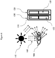
- FIG. 5 An example embodiment based on multimodal imaging using holography and fluorescence as the imaging modalities is illustrated in Fig. 5 .
- the light source 110 emits a coherent or partially coherent polarised light 160.
- the emitted light 160 illuminates a sample 900 positioned between the light source 110 and the optical filter 130.
- a transparent or partially transparent sample 900 e.g. a biological cell, provides a suitable object for digital in-line holography, but the same basic system may be used with off-axis holography or other sample/object types, e.g. large molecules, biological tissues etc.
- the multimodal imaging system 100 is suitable for implementation as a lens-free solution as illustrated in Fig. 5 , but standard optical components 200 (such as lenses, prisms, mirrors, apertures etc.) may also be incorporated between the light source, object and the image sensor 120 as illustrated in Fig. 7 and Fig. 8 .
- the first light spectrum comprises the emitted light 160, even when it only contains light which has been diffracted by the sample 900.
- the first filter element 131 receives the first light spectrum comprising the emitted light 160 and forming the diffraction pattern. The first filter element 131 allows transmission of the first light spectrum, but in so doing, attenuates the light thereby reducing its intensity.
- the primary mechanism employed for this attenuation is based on polarisation selectivity of the first filter element 131.
- the light forming the diffraction pattern then impinges on the image sensor 120, arriving only at the pixels 150 served by the first filter element 131.
- the second filter element 132 also receives the first light spectrum, but blocks its transmission based on spectral selectivity, high polarisation selectivity, or both. Consequently, pixel elements served by the second filter element 132 do not receive the first light spectrum.
- the sample 900 also comprises a fluorescent marker. Multiple fluorescent markers may also be used, but in this example only one will be used for simplicity of explanation.
- the light 160 impinges on the sample 900 it excites the fluorescent marker to emit light which comprises the second light spectrum.
- the second light spectrum differs from the first light spectrum.
- the first light spectrum and the second light spectrum have no common frequency components due to the wavelength shift between the excitation light (first light spectrum) and the resultant fluorescent light (second light spectrum). This is not a necessary requirement, but is helpful for explanation of this simple embodiment.
- the wavelength of the first light spectrum is shorter than the wavelength of the second light spectrum as is most often the case with fluorescence.
- the second light spectrum also has a different degree of polarisation (DOP) than the first light spectrum as is usually the case with fluorescence because it is normally unpolarised.
- DOP degree of polarisation
- the first light spectrum has a high DOP as it is polarised or at least partially polarised light, there is not a fixed range applicable, but the higher the DOP of the first light spectrum, the more controllable the light attenuation will be.
- the second light spectrum comprises fluorescent light in this example which is unpolarised light and has a DOP of 0% or thereabouts.
- Both the first light spectrum and the second light spectrum would then travel to the optical filter 130.
- the first light spectrum comprising the emitted light 160 and the diffracted light reaches the second filter element 132 it would be blocked by a spectral filter component because the spectrum of the emitted light 160 does not fall within its pass-band.
- the second filter element 132 is configured for transmission of the second light spectrum and would allow it to pass because it does fall within the pass-band of the spectral filter component. Consequently, the imager pixels 150 served by the second filter element 132 would receive the second light spectrum.
- This disparity between light intensities of the different imaging modes is particularly problematic when trying to capture the images simultaneously on different pixels 150 of the same image sensor 120.
- these approaches are not suitable for simultaneous multimodal imaging when using a single image sensor 120.
- the approach being adopted in this embodiment is to attenuate the passage of light associated with the higher intensity imaging mode so as to arrive at comparable light intensities for each of the imaging modes arriving at the imaging sensor 120.
- the same technique of attenuating the passage of light can be applied to both the first light spectrum and the second light spectrum if desired to further facilitate balancing their respective light intensities as may be required.
- the primary mechanism employed in this embodiment to attenuate the first light spectrum is based on the use of polarising filters.
- the emitted light 160, and hence the first light spectrum is linearly polarised, but other polarisation geometries may also be used.
- the first filter element 131 comprises a polarising filter component it can discriminate light based on polarity, and can also attenuate the passage of polarised light.
- the attenuation of light can be controlled by designing the Polarisation Extinction Ratio (PER) of the filter to match the desired attenuation and polarity of the first light spectrum.
- PER Polarisation Extinction Ratio
- a wire grid polarisation filter is employed, but other polarisation filter techniques known in the art may also be used.
- Fig. 4 illustrates a subset of suitable wire grid polarising filter implementations.
- the polarising filter may be designed with a wire grid orientation matching the polarity (polarisation angle) of the first light spectrum.
- the PER of the filter is increased, i.e. attenuation of the polarised light is increased.
- the geometric orientation of the wire grid with respect to the polarity of the polarised light may be misaligned to alter attenuation.
- the polarity of linearly polarised light is orthogonal to the wire grid, attenuation is at its minimum, and when aligned with the wire grid, then attenuation is at its maximum.
- the second filter element 132 may also comprise a polarising filter component. In the current embodiment this could be used in addition to the spectral filter component to block the second light spectrum.
- the light source 110 may comprise a laser based light source, Light Emitting Diode (LED), incandescent bulb, natural light source or other means for emitting electromagnetic radiation as known in the art.
- the light source 110 may optionally comprise planar light circuits and/or photonic integrated circuits based on waveguide components to guide and manipulate light on an optical substrate. These photonic components may contain input-coupling and output-coupling structures to interface an external light source of arbitrary nature, and emit light towards an object or scene. The emitted light may be within the visible spectrum, but is equally applicable to nonvisible spectra which imaging sensors may capture.
- the light source 110 may optionally comprise fibre components such as single-mode-fibre or multi-mode-fibre or light guides. Such fibre components may contain additional fibre components to control the degree of polarisation, spectrum and coherence of the light.
- spatial filters such as a pinhole provide a partially coherence light source 110.
- optical filters can be used to control the spectral content of the first light spectrum.
- the light source 110 may optionally comprise optical elements such as lenses, mirrors, beam splitters, prisms etc. to achieve illumination specifications such as beam shape, ray angularity and uniformity etc.
- the light source 110 may emit light continuously during imaging operations, i.e. the emitted light intensity remains constant or substantially constant over time.
- the light source 110 emits a pulsed light, wherein light is emitted for limited periods during imaging operations, each emission period being followed by a dormant period during which no light, or a significantly reduced light intensity is emitted.
- the pulsed operation can repeat more than once during the imaging process.
- the light source 110 is driven by an electronic circuit which is optionally in communication with the image sensor 120 for synchronization purposes.
- Filter elements 130 may be sensitive to the degree of polarisation and the spectrum of the light. At least one of the filter elements can reflect, absorb and transmit the light according to the polarisation property of the light impinging upon.
- Polarisation filters have a property known as Polarisation Extinction Ratio (PER) defined as the ratio of optical powers transmitted in the two orthogonal polarisation directions.
- PER Polarisation Extinction Ratio
- the PER value of a filter is intrinsic to the design of the filter. In an example of a wire-grid based polarisation selective filter, the wire-grid material and geometry determines the PER value. Higher PER values of a filter indicates the filter has transmittance properties highly selective to the polarisation state of the light, and vice versa. Filters with higher PER can block the polarised light from being transmitted through it to a greater extent than filters with lower PER.
- At least one of the filter elements 130 can reflect, absorb and transmit the light according to the spectral property of the light impinging upon.
- the spectral filters have the property of transmitting light with wavelength within its "pass-band” while blocking light with wavelength outside of its pass-band via absorbing or reflecting it.
- the pass-band is defined as a spectral band in which the light can be transmitted with higher efficiency than the light outside of this spectral band.
- the pass-band can be defined using parameters such as central wavelength, bandwidth, peak transmission, blocking ratio etc.
- Such wavelength selective filters can be designed as thin films of materials with different refractive indices, thin films of materials with birefringent properties, thin films of materials with absorbance. The relative thickness and combination of materials determine the pass-band parameters of such filters.
- Filter elements 130 can be manufactured in different size ranging from nanometre to metre scale.
- Patterning of the filters can be done with top-down conventional semiconductor processes or bottom-up self-assembly methods.
- the patterning allows to multiplex filters with different spectral and polarisation properties.
- Such filters can be positioned next to each other in the same plane orthogonal to light propagation direction and also in the plane along the light propagation direction.
- Image sensors 120 are composed of a plurality of light sensitive elements, usually referred to as pixels 150. Each pixel detects photons and converts them into electrons for digital processing of the optical signal.
- the operating parameters of image sensors vary significantly depending on the materials of their construction and manufacturing technology employed. They can be sensitive to a wide range of spectra, e.g. wavelength ranges of 200nm to 15 ⁇ m, and are able to operate with polarised light over the whole range of Degrees of Polarisation (DOP) from 0% to 100%.
- DOP Degrees of Polarisation
- the optical filter elements 131 & 132 can be patterned according to pixel 150 geometry of the image sensor 120. Pixels 150 and filter elements 131 & 132 can be geometrically aligned to each other such that each pixel 150 accepts light from a single filter element 131 or 132.
- pixels 150 comprising the image sensor 120 can be grouped according to the filter elements such that a subgroup of pixels 150 can collect light transmitted by a specific filter element. In the simplest case half the pixels 150 comprising the image sensor 120 receive light transmitted by the first filter element 131 and half the pixel elements receive light transmitted by the second filter element 132. However, any proportions of pixels 150 to filter element 131 or 132 may be employed and any size of image sensor 120. It can also be advantageous in some circumstances to use only a subset of the pixels 150 available on image sensor 120, e.g. so that some may be used for other purposes such as monitoring ambient light levels.
- the pixel 150 groupings may be contiguous or non-contiguous and multiple optical filter elements 131 & 132 can be arranged in arbitrary patterns, or repetitive patterns as may be appropriate for the application. A limited number of example filter arrangements are shown in Fig. 2 . Clearly, additional optical filter elements may be employed for additional imaging modalities using the same image sensor 120.
- data retrieved from image pixels 150 can be used to generate multiple images of a scene or a composite image of a scene, or to extract information about the scene, e.g. functional and morphological information. This information may be extracted by a computer, wherein it may be used to determine characteristics of the scene being imaged to effect a decision and/or process.
- Pixels 150 in the image sensor 120 must receive light intensity (energy flux) levels of light being transmitted by the filter elements 131 & 132 which is within the dynamic range of the pixels 150 in order to perform simultaneous read-out.
- the dynamic range of available image sensors varies, but is limited to a range (usually expressed in dB) depending on the image sensor technology. Therefore, for image sensors to be useful in multi-modal imaging the different modalities are required to output light intensity levels within the dynamic range of the image sensor 120. In practice, the requirement is much more stringent because most imaging modalities require at least an order of magnitude larger signal to noise ratio than 1.0. Hence, it is important to equalize light intensity levels (energy flux) impinging on the imager for different modalities to facilitate effective image capture in most circumstances.
- the intensity of light (energy flux) impinging on the image sensor 120 for the first light spectrum and the second light spectrum can be equalized through attenuation of the light resulting from at least one of the imaging modalities.
- the filter elements 131 & 132 establish this optical power balance between different imaging modalities on an image sensor 120 through taking advantage of the polarisation and spectral attributes of the light output from different modalities.
- Fig. 3 illustrates an example breakdown and schematic cross-sections of the filter elements 131 & 132 in terms of their stacked structure.
- the first element 131 consists of two filter components (stacked structures).
- the first filter component (top stack) (133) is a spectral filter component designed to transmit the pass-band corresponding to the first light spectrum and reflect the second light spectrum.
- the second light spectrum may correspond to the Stokes or Anti-stokes shifted light originated from an object in response to absorption of the light emitted from a light source 110.
- it may relate to non-resonant scattering of light emitted from a light source 110 or spontaneously emitted (blackbody) radiation. Any combination of these examples may be adopted to address application needs.
- the second filter component (bottom stack) 135 is a polarising filter component designed to attenuate polarised light of the first light spectrum which has been transmitted by the first filter component (top stack) 133.
- the attenuation of polarised light is an important feature of this second filter component (bottom stack) 135. It is required that the light intensity of the first light spectrum after transmission through the first filter element 131 is reduced to a level comparable with the second light spectrum after transmission through the second filter element 132 so that light impinging on the image sensor 120 falls within the dynamic range of the image sensor 120.
- the first filter element 131 attenuates the transmission of the first light spectrum while blocking transmission of the second light spectrum.
- the second filter element 132 comprises at least one filter component, in which case the filter component may be a spectral filter component or a polarising filter component. In examples where the second filter element 132 comprises two filter components arranged in the same light path (e.g. two stacked structures).
- the first filter component (top stack) 134 is a spectral filter component designed to transmit the pass-band corresponding to the second light spectrum.
- the first filter component also blocks transmission of the first light spectrum, but may partially transmit it, e.g. significantly attenuate it. This may, for example, be due to filter design, filter methodology, or circumstances where the first light spectrum and the second light spectrum have some immediately adjacent or common frequency components, e.g. some overlap in the frequency domain.
- the second filter component (bottom stack) 136 is a polarisation filter component differently designed from the polarising filter component 135 of the first filter element 131. It is designed to completely extinguish the linearly polarised first light spectrum but will also cause partial attenuation of the second light spectrum. In some application, e.g. fluorescence imaging, this is seen in the art as undesirable because of the low light intensity levels involved. However, it has been found that the advantages of balancing light levels impinging on the image sensor 120 for the different imaging modes can outweigh this minor disadvantage.
- the second light spectrum may comprise partially polarised light originating from the scene being imaged. The extent of attenuation of the second light spectrum depends on its degree of polarisation.
- the second filter element 132 comprises a spectral filter component and polarising filter component
- the second filter element 132 also attenuates the second light spectrum while blocking the first light spectrum.
- Fabry-Perrot filters are used to realize the spectral filter components of the two filter elements 133 and 134, but other interference filters, or other filter types (e.g. dichroic filters) may be used.
- design of Fabry-Perot filters comprises, an optically transparent cavity layer embedded between two partially reflective layers. The pass-band attributes of the spectral filter components of the first filter element 131 and the second filter element 132 can be tailored for the spectrally different light of the first light spectrum and the second light spectrum to separate the two light spectra as indicated above.
- wire-grid polarising filters are used to realise the polarising filter component of the filter elements 135 and 136.
- the wire-grid filters may comprise many parallel metallic wires that are placed in an optically transparent medium with a defined orientation, periodicity and thickness.
- a difference between the polarising filter components 135 & 136 of the first filter element 131 and the second filter element 132 is that the second polarising filter component 136 provides a higher polarised light extinction than the first polarising filter component 135. This provides the advantage that only the second light spectrum impinges on pixels 150 associated with the second filter element 132
- different levels of polarised light extinction can be achieved by using polarising filter components 135 & 136 with different Polarisation Extinction Ratios (PER). This can be achieved by using different materials for wires and surrounding medium of the wires, different geometry of the wires or wire repetition period as illustrated in Fig. 4 .
- PER Polarisation Extinction Ratios
- different levels of polarised light extinction can be achieved through changing the wire orientation with respect to polarisation angle of the polarised light 111 on the plane perpendicular to the light propagation as illustrated in Fig. 4 .
Landscapes
- Physics & Mathematics (AREA)
- Engineering & Computer Science (AREA)
- General Physics & Mathematics (AREA)
- Chemical & Material Sciences (AREA)
- Analytical Chemistry (AREA)
- General Health & Medical Sciences (AREA)
- Health & Medical Sciences (AREA)
- Spectroscopy & Molecular Physics (AREA)
- Biochemistry (AREA)
- Multimedia (AREA)
- Immunology (AREA)
- Pathology (AREA)
- Life Sciences & Earth Sciences (AREA)
- Optics & Photonics (AREA)
- Signal Processing (AREA)
- Medical Informatics (AREA)
- Radiology & Medical Imaging (AREA)
- Quality & Reliability (AREA)
- Computer Vision & Pattern Recognition (AREA)
- Theoretical Computer Science (AREA)
- Nuclear Medicine, Radiotherapy & Molecular Imaging (AREA)
- Investigating, Analyzing Materials By Fluorescence Or Luminescence (AREA)
Claims (15)
- Système d'imagerie multimodal (100) comprenant :une source de lumière (110),un capteur d'image (120) comprenant une pluralité de pixels (150), etun filtre optique (130) comprenant un premier élément filtre (131) et un second élément filtre (132), dans lequelle premier élément filtre (131) et le second élément filtre (132) sont agencés comme un réseau parallèle au capteur d'image (120),chaque élément filtre du filtre optique (130) est configuré pour la transmission de la lumière à un sous-ensemble de la pluralité de pixels (150), et chaque pixel (150) du sous-ensemble reçoit de la lumière par un seul élément filtre, et dans lequella source de lumière (110) émet une lumière polarisée partiellement cohérente (160),le premier élément filtre (131) est configuré pour la transmission d'un premier spectre lumineux qui comprend la lumière polarisée émise par la source de lumière (110),le second élément filtre (132) est configuré pour la transmission d'un second spectre lumineux, etle capteur d'image (120) est configuré pour capturer simultanément la lumière incidente sur celui-ci après qu'elle est passée à travers le filtre optique (130),caractérisé en ce que le premier élément filtre (131) est configuré pour atténuer l'intensité du premier spectre lumineux de sorte que le flux d'énergie de la lumière incidente sur le capteur d'image (120) pour le premier spectre lumineux et le second spectre lumineux peuvent être égalisés.
- Système d'imagerie multimodal (100) selon la revendication 1, dans lequel les composantes de fréquence du premier spectre lumineux diffèrent des composantes de fréquence du second spectre lumineux.
- Système d'imagerie multimodal (100) selon l'une quelconque des revendications précédentes,
dans lequel le degré de polarisation du premier spectre lumineux n'est pas égal au degré de polarisation du second spectre lumineux. - Système d'imagerie multimodal (100) selon l'une quelconque des revendications précédentes,
dans lequel la source de lumière (110) émet une lumière pulsée et le premier spectre lumineux comprend une première séquence d'impulsions. - Système d'imagerie multimodal (100) selon l'une quelconque des revendications précédentes,
dans lequel le flux d'énergie de la lumière incidente sur le capteur d'image (120) depuis un quelconque élément filtre du filtre optique (130) se situe dans la plage dynamique du capteur d'image (120). - Système d'imagerie multimodal (100) selon l'une quelconque des revendications précédentes, dans lequel au moins le premier élément filtre (131) comprend un composant de filtre spectral et un composant de filtre polarisant agencés dans le même trajet lumineux.
- Système d'imagerie multimodal (100) selon la revendication 5, dans lequelle second élément filtre (132) comprend également un composant de filtre polarisant, etle composant de filtre polarisant du premier élément filtre (131) présente un plus faible Rapport d'Extinction de Polarisation (REP) que le composant de filtre polarisant du second élément filtre (132).
- Système d'imagerie multimodal (100) selon l'une quelconque des revendications précédentes,
dans lequel l'un des modes d'imagerie est une imagerie holographique. - Système d'imagerie multimodal (100) selon l'une quelconque des revendications précédentes,
dans lequel l'un des modes d'imagerie est une imagerie par fluorescence. - Système d'imagerie multimodal (100) selon l'une quelconque des revendications précédentes,
dans lequel le système d'imagerie multimodal (100) est un système d'imagerie multimodal (100) sans lentille. - Appareil de caractérisation de matériel biologique, l'appareil comprenant le système d'imagerie multimodal selon l'une quelconque des revendications précédentes, et en outre un ordinateur configuré pour extraire des informations de données récupérées à partir de pixels d'image (150) pour déterminer les caractéristiques du matériel biologique.
- Procédé d'imagerie multimodal comprenant les étapes de :a) éclairage d'un échantillon (900) avec une source de lumière (110) émettant une lumière polarisée partiellement cohérente (160), générant un premier spectre lumineux comprenant la lumière polarisée émise par la source de lumière (110), et générant un second spectre lumineux,b) transmission du premier spectre lumineux et du second spectre lumineux à travers un filtre optique (130) comprenant un premier élément filtre (131) et un second élément filtre (132) agencés comme un réseau parallèle à un capteur d'image (120) comprenant une pluralité de pixels (150), dans lequel le premier spectre lumineux est transmis par le premier élément filtre (131) et le second spectre lumineux est transmis par le second élément filtre (132),c) la capture simultanée de la lumière transmise à traverse le premier élément filtre (131) avec un premier sous-ensemble de pixels d'image (150), et de la lumière transmise à travers le second élément filtre (132) avec un second sous-ensemble de pixels (150), dans lequel chaque pixel du sous-ensemble reçoit la lumière à travers un seul élément filtre,
caractérisé en ce que dans l'étape b) le premier élément filtre (131) est configuré pour atténuer l'intensité du premier spectre lumineux de sorte que le flux d'énergie de la lumière incidente sur le capteur d'image (120) pour le premier spectre lumineux et le second spectre lumineux peuvent être égalisés. - Procédé d'imagerie multimodal selon la revendication 12, dans lequel les composantes de fréquence du premier spectre lumineux diffèrent des composantes de fréquence du second spectre lumineux.
- Procédé d'imagerie multimodal selon l'une quelconque des revendications 12 et 13, dans lequel le flux d'énergie de la lumière incidente sur le capteur d'image (120) depuis un quelconque élément filtre du filtre optique (130) se situe dans la plage dynamique du capteur d'image (120).
- Procédé d'imagerie multimodal selon l'une quelconque des revendications 12 à 14 dans lequel le procédé comprend en outre les étapes de :d) lecture de données provenant du premier sous-ensemble de pixels d'image (150) du capteur d'image (120) où la lumière transmise par le premier élément filtre (131) est capturée pour créer une première image, ete) de lecture de données provenant du second sous-ensemble de pixels d'image (150) du capteur d'image (120) où la lumière transmise par le second élément filtre (131) est capturée pour créer une seconde image.
Applications Claiming Priority (1)
| Application Number | Priority Date | Filing Date | Title |
|---|---|---|---|
| EP18212415 | 2018-12-13 |
Publications (2)
| Publication Number | Publication Date |
|---|---|
| EP3667299A1 EP3667299A1 (fr) | 2020-06-17 |
| EP3667299B1 true EP3667299B1 (fr) | 2022-11-09 |
Family
ID=64901850
Family Applications (1)
| Application Number | Title | Priority Date | Filing Date |
|---|---|---|---|
| EP19211603.6A Active EP3667299B1 (fr) | 2018-12-13 | 2019-11-26 | Système d'imagerie multimodal |
Country Status (2)
| Country | Link |
|---|---|
| US (1) | US11016022B2 (fr) |
| EP (1) | EP3667299B1 (fr) |
Families Citing this family (4)
| Publication number | Priority date | Publication date | Assignee | Title |
|---|---|---|---|---|
| US20230034139A1 (en) * | 2019-12-27 | 2023-02-02 | Sony Group Corporation | Polarization imaging system and polarization imaging method |
| EP4145211A1 (fr) * | 2021-09-02 | 2023-03-08 | Leica Microsystems CMS GmbH | Appareil optique |
| WO2023057735A1 (fr) * | 2021-10-05 | 2023-04-13 | Dmg Biophotonics Limited | Appareil et procédé de mesure de propriétés de multiples caractéristiques de rayonnement |
| CN114330488A (zh) * | 2021-11-19 | 2022-04-12 | 浪潮(北京)电子信息产业有限公司 | 一种多模态数据处理方法、装置、设备及存储介质 |
Family Cites Families (37)
| Publication number | Priority date | Publication date | Assignee | Title |
|---|---|---|---|---|
| US5751384A (en) * | 1995-05-23 | 1998-05-12 | The Board Of Regents Of The University Of Colorado | Color polarizers for polarizing an additive color spectrum along a first axis and it's compliment along a second axis |
| US20040111031A1 (en) * | 1999-07-22 | 2004-06-10 | Alfano Robert R. | Spectral polarizing tomographic dermatoscope |
| US6826424B1 (en) * | 2000-12-19 | 2004-11-30 | Haishan Zeng | Methods and apparatus for fluorescence and reflectance imaging and spectroscopy and for contemporaneous measurements of electromagnetic radiation with multiple measuring devices |
| US6570659B2 (en) * | 2001-03-16 | 2003-05-27 | Lightlab Imaging, Llc | Broadband light source system and method and light source combiner |
| US7016717B2 (en) * | 2002-07-05 | 2006-03-21 | The Regents Of The University Of California | Near-infrared spectroscopic tissue imaging for medical applications |
| PL1631788T3 (pl) | 2003-05-16 | 2007-08-31 | Univ Bruxelles | Cyfrowy mikroskop holograficzny do trójwymiarowego obrazowania i sposób jego stosowania |
| US7072039B2 (en) * | 2003-08-20 | 2006-07-04 | Itt Manufacturing Enterprises, Inc. | Active multiple-color imaging polarimetry |
| AU2003272531A1 (en) * | 2003-09-15 | 2005-04-27 | Beth Israel Deaconess Medical Center | Medical imaging systems |
| US7920908B2 (en) * | 2003-10-16 | 2011-04-05 | David Hattery | Multispectral imaging for quantitative contrast of functional and structural features of layers inside optically dense media such as tissue |
| US7530948B2 (en) * | 2005-02-28 | 2009-05-12 | University Of Washington | Tethered capsule endoscope for Barrett's Esophagus screening |
| US20090262408A1 (en) | 2005-08-30 | 2009-10-22 | Pioneer Corporation | Optical pickup apparatus and hologram recording and reproducing system |
| US7382456B2 (en) * | 2005-12-29 | 2008-06-03 | Honeywell Asca, Inc. | Spectroscopic sensor for measuring sheet properties |
| US20080118886A1 (en) | 2006-11-21 | 2008-05-22 | Rongguang Liang | Apparatus for dental oct imaging |
| GB0707433D0 (en) * | 2007-04-18 | 2007-05-23 | Stfc Science & Technology | Fluorescence measurement |
| WO2010004365A1 (fr) * | 2008-07-10 | 2010-01-14 | Ecole Polytechnique Federale De Lausanne (Epfl) | Imagerie optique cohérente fonctionnelle |
| JP5572326B2 (ja) * | 2009-03-26 | 2014-08-13 | オリンパス株式会社 | 画像処理装置、撮像装置、画像処理プログラムおよび画像処理方法 |
| US8467858B2 (en) * | 2009-04-29 | 2013-06-18 | Tomophase Corporation | Image-guided thermotherapy based on selective tissue thermal treatment |
| US8357281B2 (en) * | 2009-09-21 | 2013-01-22 | Advanced Analytical Technologies, Inc. | Multi-wavelength fluorescence detection system for multiplexed capillary electrophoresis |
| EP2491366B1 (fr) | 2009-10-20 | 2016-12-28 | The Regents of The University of California | Cellule holographique incohérente sans lentille et microscopie sur une puce |
| US20110292258A1 (en) * | 2010-05-28 | 2011-12-01 | C2Cure, Inc. | Two sensor imaging systems |
| US8408821B2 (en) * | 2010-10-12 | 2013-04-02 | Omnivision Technologies, Inc. | Visible and infrared dual mode imaging system |
| US10126709B2 (en) | 2013-12-02 | 2018-11-13 | Imec Vzw | Apparatus and method for performing in-line lens-free digital holography of an object |
| JP6005303B2 (ja) * | 2014-04-08 | 2016-10-12 | オリンパス株式会社 | 蛍光観察内視鏡システム |
| JP6065875B2 (ja) * | 2014-06-02 | 2017-01-25 | 横河電機株式会社 | 偏光検査装置 |
| US10398294B2 (en) * | 2014-07-24 | 2019-09-03 | Z Square Ltd. | Illumination sources for multicore fiber endoscopes |
| US9574989B2 (en) | 2014-08-08 | 2017-02-21 | Omnivision Technologies, Inc. | Lens-free imaging system and method for detecting particles in sample deposited on image sensor |
| US9787916B2 (en) * | 2014-10-28 | 2017-10-10 | The Boeing Company | Active real-time characterization system |
| EP3206560B1 (fr) * | 2014-12-25 | 2024-06-12 | Sony Group Corporation | Système d'imagerie médicale et dispositif d'éclairage |
| US10390718B2 (en) * | 2015-03-20 | 2019-08-27 | East Carolina University | Multi-spectral physiologic visualization (MSPV) using laser imaging methods and systems for blood flow and perfusion imaging and quantification in an endoscopic design |
| JP6764880B2 (ja) * | 2015-12-11 | 2020-10-07 | 株式会社ニコン | 偏光特性画像計測装置、偏光特性画像計測方法 |
| WO2017196995A1 (fr) | 2016-05-11 | 2017-11-16 | The Regents Of The University Of California | Procédé et système pour super-résolution de pixels d'images couleurs holographiques multiplexées |
| WO2017201093A1 (fr) * | 2016-05-17 | 2017-11-23 | Hypermed Imaging, Inc. | Imageur hyperspectral couplé à une poursuite de molécules indicatrices |
| US20190137932A1 (en) | 2016-05-25 | 2019-05-09 | The Regents Of The University Of California | Wide-field imaging of birefringent crystals and other materials using lens-free polarized microscope |
| WO2018070451A1 (fr) | 2016-10-11 | 2018-04-19 | 国立大学法人神戸大学 | Microscope holographique numérique |
| US10394008B2 (en) * | 2016-10-19 | 2019-08-27 | Cornell University | Hyperspectral multiphoton microscope for biomedical applications |
| CN110545709B (zh) * | 2017-05-08 | 2022-04-26 | 索尼公司 | 图像获取系统、图像获取方法、控制装置和控制方法 |
| CN113950279B (zh) * | 2019-04-08 | 2023-04-14 | 艾科缇弗外科公司 | 用于医疗成像的系统和方法 |
-
2019
- 2019-11-26 EP EP19211603.6A patent/EP3667299B1/fr active Active
- 2019-12-13 US US16/713,549 patent/US11016022B2/en active Active
Also Published As
| Publication number | Publication date |
|---|---|
| US20200191706A1 (en) | 2020-06-18 |
| US11016022B2 (en) | 2021-05-25 |
| EP3667299A1 (fr) | 2020-06-17 |
Similar Documents
| Publication | Publication Date | Title |
|---|---|---|
| EP3667299B1 (fr) | Système d'imagerie multimodal | |
| CN105493258B (zh) | 用于样本的缺陷检测及光致发光测量的系统及方法 | |
| US11131840B2 (en) | Microscope system and method for microscopic imaging | |
| US9041930B1 (en) | Digital pathology system | |
| KR20200101851A (ko) | 칩 상의 분광계 | |
| CA2996969C (fr) | Microscope mobile | |
| JP2008502929A (ja) | 反射または透過赤外光による微細構造の検査装置または検査方法 | |
| Brydegaard et al. | Versatile multispectral microscope based on light emitting diodes | |
| JP2014515179A (ja) | 光ガイドピクセル | |
| US9739716B2 (en) | Method for regulating the relative position of an analyte in relation to a light beam | |
| CN105548096B (zh) | 具有嵌入的微流体的色彩感测影像传感器和相关方法 | |
| US11041756B2 (en) | Method and apparatus of filtering light using a spectrometer enhanced with additional spectral filters with optical analysis of fluorescence and scattered light from particles suspended in a liquid medium using confocal and non confocal illumination and imaging | |
| US8633432B2 (en) | Reflective focusing and transmissive projection device | |
| WO2017005153A1 (fr) | Source de lumière antireflet à égalisation de la lumière, et dispositif de capture d'image comportant cette source | |
| CN109073875A (zh) | 用于可选择角度地照明的照明模块 | |
| AU2007237486A1 (en) | Apparatus and method for optically examining security documents | |
| WO2022218329A1 (fr) | Procédé et système de traitement par pcr quantitative par fluorescence | |
| EP3227740B1 (fr) | Cytomètre d'image | |
| US20160327433A1 (en) | Title: integrated packaging for multi-component sensors | |
| CN115876789A (zh) | 一种暗场成像方法和装置 | |
| JP2009009139A (ja) | 波長特異的位相顕微鏡検査法 | |
| CN113711013A (zh) | 样品分析方法、分析装置及计算机程序 | |
| JP2005524069A (ja) | 励起光源として発光ダイオードを有する蛍光検出装置及び方法 | |
| US20230288339A1 (en) | Rapid Optical Analysis System | |
| WO2018062412A1 (fr) | Système d'acquisition d'image et procédé d'acquisition d'image |
Legal Events
| Date | Code | Title | Description |
|---|---|---|---|
| PUAI | Public reference made under article 153(3) epc to a published international application that has entered the european phase |
Free format text: ORIGINAL CODE: 0009012 |
|
| STAA | Information on the status of an ep patent application or granted ep patent |
Free format text: STATUS: THE APPLICATION HAS BEEN PUBLISHED |
|
| AK | Designated contracting states |
Kind code of ref document: A1 Designated state(s): AL AT BE BG CH CY CZ DE DK EE ES FI FR GB GR HR HU IE IS IT LI LT LU LV MC MK MT NL NO PL PT RO RS SE SI SK SM TR |
|
| AX | Request for extension of the european patent |
Extension state: BA ME |
|
| STAA | Information on the status of an ep patent application or granted ep patent |
Free format text: STATUS: REQUEST FOR EXAMINATION WAS MADE |
|
| 17P | Request for examination filed |
Effective date: 20201210 |
|
| RBV | Designated contracting states (corrected) |
Designated state(s): AL AT BE BG CH CY CZ DE DK EE ES FI FR GB GR HR HU IE IS IT LI LT LU LV MC MK MT NL NO PL PT RO RS SE SI SK SM TR |
|
| GRAP | Despatch of communication of intention to grant a patent |
Free format text: ORIGINAL CODE: EPIDOSNIGR1 |
|
| STAA | Information on the status of an ep patent application or granted ep patent |
Free format text: STATUS: GRANT OF PATENT IS INTENDED |
|
| RIC1 | Information provided on ipc code assigned before grant |
Ipc: G01N 21/21 20060101ALI20220429BHEP Ipc: G01N 21/25 20060101ALI20220429BHEP Ipc: G01N 21/65 20060101ALI20220429BHEP Ipc: G01N 21/17 20060101ALI20220429BHEP Ipc: G01N 21/64 20060101AFI20220429BHEP |
|
| INTG | Intention to grant announced |
Effective date: 20220520 |
|
| GRAS | Grant fee paid |
Free format text: ORIGINAL CODE: EPIDOSNIGR3 |
|
| GRAA | (expected) grant |
Free format text: ORIGINAL CODE: 0009210 |
|
| STAA | Information on the status of an ep patent application or granted ep patent |
Free format text: STATUS: THE PATENT HAS BEEN GRANTED |
|
| AK | Designated contracting states |
Kind code of ref document: B1 Designated state(s): AL AT BE BG CH CY CZ DE DK EE ES FI FR GB GR HR HU IE IS IT LI LT LU LV MC MK MT NL NO PL PT RO RS SE SI SK SM TR |
|
| REG | Reference to a national code |
Ref country code: GB Ref legal event code: FG4D |
|
| REG | Reference to a national code |
Ref country code: CH Ref legal event code: EP Ref country code: AT Ref legal event code: REF Ref document number: 1530689 Country of ref document: AT Kind code of ref document: T Effective date: 20221115 |
|
| REG | Reference to a national code |
Ref country code: DE Ref legal event code: R096 Ref document number: 602019021651 Country of ref document: DE |
|
| REG | Reference to a national code |
Ref country code: IE Ref legal event code: FG4D |
|
| REG | Reference to a national code |
Ref country code: LT Ref legal event code: MG9D |
|
| REG | Reference to a national code |
Ref country code: NL Ref legal event code: MP Effective date: 20221109 |
|
| REG | Reference to a national code |
Ref country code: AT Ref legal event code: MK05 Ref document number: 1530689 Country of ref document: AT Kind code of ref document: T Effective date: 20221109 |
|
| PG25 | Lapsed in a contracting state [announced via postgrant information from national office to epo] |
Ref country code: SE Free format text: LAPSE BECAUSE OF FAILURE TO SUBMIT A TRANSLATION OF THE DESCRIPTION OR TO PAY THE FEE WITHIN THE PRESCRIBED TIME-LIMIT Effective date: 20221109 Ref country code: PT Free format text: LAPSE BECAUSE OF FAILURE TO SUBMIT A TRANSLATION OF THE DESCRIPTION OR TO PAY THE FEE WITHIN THE PRESCRIBED TIME-LIMIT Effective date: 20230309 Ref country code: NO Free format text: LAPSE BECAUSE OF FAILURE TO SUBMIT A TRANSLATION OF THE DESCRIPTION OR TO PAY THE FEE WITHIN THE PRESCRIBED TIME-LIMIT Effective date: 20230209 Ref country code: LT Free format text: LAPSE BECAUSE OF FAILURE TO SUBMIT A TRANSLATION OF THE DESCRIPTION OR TO PAY THE FEE WITHIN THE PRESCRIBED TIME-LIMIT Effective date: 20221109 Ref country code: FI Free format text: LAPSE BECAUSE OF FAILURE TO SUBMIT A TRANSLATION OF THE DESCRIPTION OR TO PAY THE FEE WITHIN THE PRESCRIBED TIME-LIMIT Effective date: 20221109 Ref country code: ES Free format text: LAPSE BECAUSE OF FAILURE TO SUBMIT A TRANSLATION OF THE DESCRIPTION OR TO PAY THE FEE WITHIN THE PRESCRIBED TIME-LIMIT Effective date: 20221109 Ref country code: AT Free format text: LAPSE BECAUSE OF FAILURE TO SUBMIT A TRANSLATION OF THE DESCRIPTION OR TO PAY THE FEE WITHIN THE PRESCRIBED TIME-LIMIT Effective date: 20221109 |
|
| PG25 | Lapsed in a contracting state [announced via postgrant information from national office to epo] |
Ref country code: RS Free format text: LAPSE BECAUSE OF FAILURE TO SUBMIT A TRANSLATION OF THE DESCRIPTION OR TO PAY THE FEE WITHIN THE PRESCRIBED TIME-LIMIT Effective date: 20221109 Ref country code: PL Free format text: LAPSE BECAUSE OF FAILURE TO SUBMIT A TRANSLATION OF THE DESCRIPTION OR TO PAY THE FEE WITHIN THE PRESCRIBED TIME-LIMIT Effective date: 20221109 Ref country code: LV Free format text: LAPSE BECAUSE OF FAILURE TO SUBMIT A TRANSLATION OF THE DESCRIPTION OR TO PAY THE FEE WITHIN THE PRESCRIBED TIME-LIMIT Effective date: 20221109 Ref country code: IS Free format text: LAPSE BECAUSE OF FAILURE TO SUBMIT A TRANSLATION OF THE DESCRIPTION OR TO PAY THE FEE WITHIN THE PRESCRIBED TIME-LIMIT Effective date: 20230309 Ref country code: HR Free format text: LAPSE BECAUSE OF FAILURE TO SUBMIT A TRANSLATION OF THE DESCRIPTION OR TO PAY THE FEE WITHIN THE PRESCRIBED TIME-LIMIT Effective date: 20221109 Ref country code: GR Free format text: LAPSE BECAUSE OF FAILURE TO SUBMIT A TRANSLATION OF THE DESCRIPTION OR TO PAY THE FEE WITHIN THE PRESCRIBED TIME-LIMIT Effective date: 20230210 |
|
| P01 | Opt-out of the competence of the unified patent court (upc) registered |
Effective date: 20230513 |
|
| PG25 | Lapsed in a contracting state [announced via postgrant information from national office to epo] |
Ref country code: NL Free format text: LAPSE BECAUSE OF FAILURE TO SUBMIT A TRANSLATION OF THE DESCRIPTION OR TO PAY THE FEE WITHIN THE PRESCRIBED TIME-LIMIT Effective date: 20221109 |
|
| REG | Reference to a national code |
Ref country code: CH Ref legal event code: PL |
|
| REG | Reference to a national code |
Ref country code: BE Ref legal event code: MM Effective date: 20221130 |
|
| PG25 | Lapsed in a contracting state [announced via postgrant information from national office to epo] |
Ref country code: SM Free format text: LAPSE BECAUSE OF FAILURE TO SUBMIT A TRANSLATION OF THE DESCRIPTION OR TO PAY THE FEE WITHIN THE PRESCRIBED TIME-LIMIT Effective date: 20221109 Ref country code: RO Free format text: LAPSE BECAUSE OF FAILURE TO SUBMIT A TRANSLATION OF THE DESCRIPTION OR TO PAY THE FEE WITHIN THE PRESCRIBED TIME-LIMIT Effective date: 20221109 Ref country code: LI Free format text: LAPSE BECAUSE OF NON-PAYMENT OF DUE FEES Effective date: 20221130 Ref country code: EE Free format text: LAPSE BECAUSE OF FAILURE TO SUBMIT A TRANSLATION OF THE DESCRIPTION OR TO PAY THE FEE WITHIN THE PRESCRIBED TIME-LIMIT Effective date: 20221109 Ref country code: DK Free format text: LAPSE BECAUSE OF FAILURE TO SUBMIT A TRANSLATION OF THE DESCRIPTION OR TO PAY THE FEE WITHIN THE PRESCRIBED TIME-LIMIT Effective date: 20221109 Ref country code: CZ Free format text: LAPSE BECAUSE OF FAILURE TO SUBMIT A TRANSLATION OF THE DESCRIPTION OR TO PAY THE FEE WITHIN THE PRESCRIBED TIME-LIMIT Effective date: 20221109 Ref country code: CH Free format text: LAPSE BECAUSE OF NON-PAYMENT OF DUE FEES Effective date: 20221130 |
|
| REG | Reference to a national code |
Ref country code: DE Ref legal event code: R097 Ref document number: 602019021651 Country of ref document: DE |
|
| PG25 | Lapsed in a contracting state [announced via postgrant information from national office to epo] |
Ref country code: SK Free format text: LAPSE BECAUSE OF FAILURE TO SUBMIT A TRANSLATION OF THE DESCRIPTION OR TO PAY THE FEE WITHIN THE PRESCRIBED TIME-LIMIT Effective date: 20221109 Ref country code: LU Free format text: LAPSE BECAUSE OF NON-PAYMENT OF DUE FEES Effective date: 20221126 Ref country code: AL Free format text: LAPSE BECAUSE OF FAILURE TO SUBMIT A TRANSLATION OF THE DESCRIPTION OR TO PAY THE FEE WITHIN THE PRESCRIBED TIME-LIMIT Effective date: 20221109 |
|
| PLBE | No opposition filed within time limit |
Free format text: ORIGINAL CODE: 0009261 |
|
| STAA | Information on the status of an ep patent application or granted ep patent |
Free format text: STATUS: NO OPPOSITION FILED WITHIN TIME LIMIT |
|
| 26N | No opposition filed |
Effective date: 20230810 |
|
| PG25 | Lapsed in a contracting state [announced via postgrant information from national office to epo] |
Ref country code: IE Free format text: LAPSE BECAUSE OF NON-PAYMENT OF DUE FEES Effective date: 20221126 |
|
| PG25 | Lapsed in a contracting state [announced via postgrant information from national office to epo] |
Ref country code: SI Free format text: LAPSE BECAUSE OF FAILURE TO SUBMIT A TRANSLATION OF THE DESCRIPTION OR TO PAY THE FEE WITHIN THE PRESCRIBED TIME-LIMIT Effective date: 20221109 Ref country code: FR Free format text: LAPSE BECAUSE OF NON-PAYMENT OF DUE FEES Effective date: 20230109 Ref country code: BE Free format text: LAPSE BECAUSE OF NON-PAYMENT OF DUE FEES Effective date: 20221130 |
|
| PG25 | Lapsed in a contracting state [announced via postgrant information from national office to epo] |
Ref country code: HU Free format text: LAPSE BECAUSE OF FAILURE TO SUBMIT A TRANSLATION OF THE DESCRIPTION OR TO PAY THE FEE WITHIN THE PRESCRIBED TIME-LIMIT; INVALID AB INITIO Effective date: 20191126 |
|
| PG25 | Lapsed in a contracting state [announced via postgrant information from national office to epo] |
Ref country code: CY Free format text: LAPSE BECAUSE OF FAILURE TO SUBMIT A TRANSLATION OF THE DESCRIPTION OR TO PAY THE FEE WITHIN THE PRESCRIBED TIME-LIMIT Effective date: 20221109 |
|
| PG25 | Lapsed in a contracting state [announced via postgrant information from national office to epo] |
Ref country code: MK Free format text: LAPSE BECAUSE OF FAILURE TO SUBMIT A TRANSLATION OF THE DESCRIPTION OR TO PAY THE FEE WITHIN THE PRESCRIBED TIME-LIMIT Effective date: 20221109 Ref country code: IT Free format text: LAPSE BECAUSE OF FAILURE TO SUBMIT A TRANSLATION OF THE DESCRIPTION OR TO PAY THE FEE WITHIN THE PRESCRIBED TIME-LIMIT Effective date: 20221109 |
|
| PG25 | Lapsed in a contracting state [announced via postgrant information from national office to epo] |
Ref country code: MC Free format text: LAPSE BECAUSE OF FAILURE TO SUBMIT A TRANSLATION OF THE DESCRIPTION OR TO PAY THE FEE WITHIN THE PRESCRIBED TIME-LIMIT Effective date: 20221109 |
|
| PG25 | Lapsed in a contracting state [announced via postgrant information from national office to epo] |
Ref country code: TR Free format text: LAPSE BECAUSE OF FAILURE TO SUBMIT A TRANSLATION OF THE DESCRIPTION OR TO PAY THE FEE WITHIN THE PRESCRIBED TIME-LIMIT Effective date: 20221109 Ref country code: MC Free format text: LAPSE BECAUSE OF FAILURE TO SUBMIT A TRANSLATION OF THE DESCRIPTION OR TO PAY THE FEE WITHIN THE PRESCRIBED TIME-LIMIT Effective date: 20221109 |
|
| GBPC | Gb: european patent ceased through non-payment of renewal fee |
Effective date: 20231126 |
|
| PG25 | Lapsed in a contracting state [announced via postgrant information from national office to epo] |
Ref country code: BG Free format text: LAPSE BECAUSE OF FAILURE TO SUBMIT A TRANSLATION OF THE DESCRIPTION OR TO PAY THE FEE WITHIN THE PRESCRIBED TIME-LIMIT Effective date: 20221109 |
|
| PG25 | Lapsed in a contracting state [announced via postgrant information from national office to epo] |
Ref country code: MT Free format text: LAPSE BECAUSE OF FAILURE TO SUBMIT A TRANSLATION OF THE DESCRIPTION OR TO PAY THE FEE WITHIN THE PRESCRIBED TIME-LIMIT Effective date: 20221109 |
|
| PG25 | Lapsed in a contracting state [announced via postgrant information from national office to epo] |
Ref country code: GB Free format text: LAPSE BECAUSE OF NON-PAYMENT OF DUE FEES Effective date: 20231126 |
|
| PG25 | Lapsed in a contracting state [announced via postgrant information from national office to epo] |
Ref country code: GB Free format text: LAPSE BECAUSE OF NON-PAYMENT OF DUE FEES Effective date: 20231126 |
|
| PGFP | Annual fee paid to national office [announced via postgrant information from national office to epo] |
Ref country code: DE Payment date: 20241022 Year of fee payment: 6 |