EP3667125A1 - Drive device for vehicle - Google Patents
Drive device for vehicle Download PDFInfo
- Publication number
- EP3667125A1 EP3667125A1 EP18866903.0A EP18866903A EP3667125A1 EP 3667125 A1 EP3667125 A1 EP 3667125A1 EP 18866903 A EP18866903 A EP 18866903A EP 3667125 A1 EP3667125 A1 EP 3667125A1
- Authority
- EP
- European Patent Office
- Prior art keywords
- oil
- electrical machine
- rotating electrical
- case
- speed reduction
- Prior art date
- Legal status (The legal status is an assumption and is not a legal conclusion. Google has not performed a legal analysis and makes no representation as to the accuracy of the status listed.)
- Granted
Links
Images


Classifications
-
- F—MECHANICAL ENGINEERING; LIGHTING; HEATING; WEAPONS; BLASTING
- F16—ENGINEERING ELEMENTS AND UNITS; GENERAL MEASURES FOR PRODUCING AND MAINTAINING EFFECTIVE FUNCTIONING OF MACHINES OR INSTALLATIONS; THERMAL INSULATION IN GENERAL
- F16H—GEARING
- F16H57/00—General details of gearing
- F16H57/04—Features relating to lubrication or cooling or heating
- F16H57/048—Type of gearings to be lubricated, cooled or heated
- F16H57/0482—Gearings with gears having orbital motion
- F16H57/0483—Axle or inter-axle differentials
-
- B—PERFORMING OPERATIONS; TRANSPORTING
- B60—VEHICLES IN GENERAL
- B60K—ARRANGEMENT OR MOUNTING OF PROPULSION UNITS OR OF TRANSMISSIONS IN VEHICLES; ARRANGEMENT OR MOUNTING OF PLURAL DIVERSE PRIME-MOVERS IN VEHICLES; AUXILIARY DRIVES FOR VEHICLES; INSTRUMENTATION OR DASHBOARDS FOR VEHICLES; ARRANGEMENTS IN CONNECTION WITH COOLING, AIR INTAKE, GAS EXHAUST OR FUEL SUPPLY OF PROPULSION UNITS IN VEHICLES
- B60K17/00—Arrangement or mounting of transmissions in vehicles
- B60K17/04—Arrangement or mounting of transmissions in vehicles characterised by arrangement, location or kind of gearing
- B60K17/16—Arrangement or mounting of transmissions in vehicles characterised by arrangement, location or kind of gearing of differential gearing
-
- B—PERFORMING OPERATIONS; TRANSPORTING
- B60—VEHICLES IN GENERAL
- B60K—ARRANGEMENT OR MOUNTING OF PROPULSION UNITS OR OF TRANSMISSIONS IN VEHICLES; ARRANGEMENT OR MOUNTING OF PLURAL DIVERSE PRIME-MOVERS IN VEHICLES; AUXILIARY DRIVES FOR VEHICLES; INSTRUMENTATION OR DASHBOARDS FOR VEHICLES; ARRANGEMENTS IN CONNECTION WITH COOLING, AIR INTAKE, GAS EXHAUST OR FUEL SUPPLY OF PROPULSION UNITS IN VEHICLES
- B60K1/00—Arrangement or mounting of electrical propulsion units
-
- B—PERFORMING OPERATIONS; TRANSPORTING
- B60—VEHICLES IN GENERAL
- B60L—PROPULSION OF ELECTRICALLY-PROPELLED VEHICLES; SUPPLYING ELECTRIC POWER FOR AUXILIARY EQUIPMENT OF ELECTRICALLY-PROPELLED VEHICLES; ELECTRODYNAMIC BRAKE SYSTEMS FOR VEHICLES IN GENERAL; MAGNETIC SUSPENSION OR LEVITATION FOR VEHICLES; MONITORING OPERATING VARIABLES OF ELECTRICALLY-PROPELLED VEHICLES; ELECTRIC SAFETY DEVICES FOR ELECTRICALLY-PROPELLED VEHICLES
- B60L15/00—Methods, circuits, or devices for controlling the traction-motor speed of electrically-propelled vehicles
- B60L15/20—Methods, circuits, or devices for controlling the traction-motor speed of electrically-propelled vehicles for control of the vehicle or its driving motor to achieve a desired performance, e.g. speed, torque, programmed variation of speed
- B60L15/2036—Electric differentials, e.g. for supporting steering vehicles
-
- F—MECHANICAL ENGINEERING; LIGHTING; HEATING; WEAPONS; BLASTING
- F16—ENGINEERING ELEMENTS AND UNITS; GENERAL MEASURES FOR PRODUCING AND MAINTAINING EFFECTIVE FUNCTIONING OF MACHINES OR INSTALLATIONS; THERMAL INSULATION IN GENERAL
- F16H—GEARING
- F16H1/00—Toothed gearings for conveying rotary motion
- F16H1/28—Toothed gearings for conveying rotary motion with gears having orbital motion
-
- F—MECHANICAL ENGINEERING; LIGHTING; HEATING; WEAPONS; BLASTING
- F16—ENGINEERING ELEMENTS AND UNITS; GENERAL MEASURES FOR PRODUCING AND MAINTAINING EFFECTIVE FUNCTIONING OF MACHINES OR INSTALLATIONS; THERMAL INSULATION IN GENERAL
- F16H—GEARING
- F16H48/00—Differential gearings
- F16H48/06—Differential gearings with gears having orbital motion
-
- F—MECHANICAL ENGINEERING; LIGHTING; HEATING; WEAPONS; BLASTING
- F16—ENGINEERING ELEMENTS AND UNITS; GENERAL MEASURES FOR PRODUCING AND MAINTAINING EFFECTIVE FUNCTIONING OF MACHINES OR INSTALLATIONS; THERMAL INSULATION IN GENERAL
- F16H—GEARING
- F16H57/00—General details of gearing
- F16H57/04—Features relating to lubrication or cooling or heating
-
- F—MECHANICAL ENGINEERING; LIGHTING; HEATING; WEAPONS; BLASTING
- F16—ENGINEERING ELEMENTS AND UNITS; GENERAL MEASURES FOR PRODUCING AND MAINTAINING EFFECTIVE FUNCTIONING OF MACHINES OR INSTALLATIONS; THERMAL INSULATION IN GENERAL
- F16H—GEARING
- F16H57/00—General details of gearing
- F16H57/04—Features relating to lubrication or cooling or heating
- F16H57/0409—Features relating to lubrication or cooling or heating characterised by increasing efficiency, e.g. by reducing splash losses
-
- F—MECHANICAL ENGINEERING; LIGHTING; HEATING; WEAPONS; BLASTING
- F16—ENGINEERING ELEMENTS AND UNITS; GENERAL MEASURES FOR PRODUCING AND MAINTAINING EFFECTIVE FUNCTIONING OF MACHINES OR INSTALLATIONS; THERMAL INSULATION IN GENERAL
- F16H—GEARING
- F16H57/00—General details of gearing
- F16H57/04—Features relating to lubrication or cooling or heating
- F16H57/0447—Control of lubricant levels, e.g. lubricant level control dependent on temperature
-
- F—MECHANICAL ENGINEERING; LIGHTING; HEATING; WEAPONS; BLASTING
- F16—ENGINEERING ELEMENTS AND UNITS; GENERAL MEASURES FOR PRODUCING AND MAINTAINING EFFECTIVE FUNCTIONING OF MACHINES OR INSTALLATIONS; THERMAL INSULATION IN GENERAL
- F16H—GEARING
- F16H57/00—General details of gearing
- F16H57/04—Features relating to lubrication or cooling or heating
- F16H57/0456—Lubrication by injection; Injection nozzles or tubes therefor
-
- F—MECHANICAL ENGINEERING; LIGHTING; HEATING; WEAPONS; BLASTING
- F16—ENGINEERING ELEMENTS AND UNITS; GENERAL MEASURES FOR PRODUCING AND MAINTAINING EFFECTIVE FUNCTIONING OF MACHINES OR INSTALLATIONS; THERMAL INSULATION IN GENERAL
- F16H—GEARING
- F16H57/00—General details of gearing
- F16H57/04—Features relating to lubrication or cooling or heating
- F16H57/0467—Elements of gearings to be lubricated, cooled or heated
- F16H57/0476—Electric machines and gearing, i.e. joint lubrication or cooling or heating thereof
-
- F—MECHANICAL ENGINEERING; LIGHTING; HEATING; WEAPONS; BLASTING
- F16—ENGINEERING ELEMENTS AND UNITS; GENERAL MEASURES FOR PRODUCING AND MAINTAINING EFFECTIVE FUNCTIONING OF MACHINES OR INSTALLATIONS; THERMAL INSULATION IN GENERAL
- F16H—GEARING
- F16H57/00—General details of gearing
- F16H57/04—Features relating to lubrication or cooling or heating
- F16H57/048—Type of gearings to be lubricated, cooled or heated
- F16H57/0482—Gearings with gears having orbital motion
- F16H57/0486—Gearings with gears having orbital motion with fixed gear ratio
-
- H—ELECTRICITY
- H02—GENERATION; CONVERSION OR DISTRIBUTION OF ELECTRIC POWER
- H02K—DYNAMO-ELECTRIC MACHINES
- H02K1/00—Details of the magnetic circuit
- H02K1/06—Details of the magnetic circuit characterised by the shape, form or construction
- H02K1/22—Rotating parts of the magnetic circuit
- H02K1/32—Rotating parts of the magnetic circuit with channels or ducts for flow of cooling medium
-
- H—ELECTRICITY
- H02—GENERATION; CONVERSION OR DISTRIBUTION OF ELECTRIC POWER
- H02K—DYNAMO-ELECTRIC MACHINES
- H02K7/00—Arrangements for handling mechanical energy structurally associated with dynamo-electric machines, e.g. structural association with mechanical driving motors or auxiliary dynamo-electric machines
- H02K7/006—Structural association of a motor or generator with the drive train of a motor vehicle
-
- H—ELECTRICITY
- H02—GENERATION; CONVERSION OR DISTRIBUTION OF ELECTRIC POWER
- H02K—DYNAMO-ELECTRIC MACHINES
- H02K7/00—Arrangements for handling mechanical energy structurally associated with dynamo-electric machines, e.g. structural association with mechanical driving motors or auxiliary dynamo-electric machines
- H02K7/10—Structural association with clutches, brakes, gears, pulleys or mechanical starters
- H02K7/116—Structural association with clutches, brakes, gears, pulleys or mechanical starters with gears
-
- H—ELECTRICITY
- H02—GENERATION; CONVERSION OR DISTRIBUTION OF ELECTRIC POWER
- H02K—DYNAMO-ELECTRIC MACHINES
- H02K9/00—Arrangements for cooling or ventilating
- H02K9/19—Arrangements for cooling or ventilating for machines with closed casing and closed-circuit cooling using a liquid cooling medium, e.g. oil
-
- B—PERFORMING OPERATIONS; TRANSPORTING
- B60—VEHICLES IN GENERAL
- B60K—ARRANGEMENT OR MOUNTING OF PROPULSION UNITS OR OF TRANSMISSIONS IN VEHICLES; ARRANGEMENT OR MOUNTING OF PLURAL DIVERSE PRIME-MOVERS IN VEHICLES; AUXILIARY DRIVES FOR VEHICLES; INSTRUMENTATION OR DASHBOARDS FOR VEHICLES; ARRANGEMENTS IN CONNECTION WITH COOLING, AIR INTAKE, GAS EXHAUST OR FUEL SUPPLY OF PROPULSION UNITS IN VEHICLES
- B60K1/00—Arrangement or mounting of electrical propulsion units
- B60K2001/001—Arrangement or mounting of electrical propulsion units one motor mounted on a propulsion axle for rotating right and left wheels of this axle
-
- B—PERFORMING OPERATIONS; TRANSPORTING
- B60—VEHICLES IN GENERAL
- B60Y—INDEXING SCHEME RELATING TO ASPECTS CROSS-CUTTING VEHICLE TECHNOLOGY
- B60Y2306/00—Other features of vehicle sub-units
- B60Y2306/03—Lubrication
-
- F—MECHANICAL ENGINEERING; LIGHTING; HEATING; WEAPONS; BLASTING
- F16—ENGINEERING ELEMENTS AND UNITS; GENERAL MEASURES FOR PRODUCING AND MAINTAINING EFFECTIVE FUNCTIONING OF MACHINES OR INSTALLATIONS; THERMAL INSULATION IN GENERAL
- F16H—GEARING
- F16H1/00—Toothed gearings for conveying rotary motion
- F16H1/28—Toothed gearings for conveying rotary motion with gears having orbital motion
- F16H1/46—Systems consisting of a plurality of gear trains each with orbital gears, i.e. systems having three or more central gears
-
- F—MECHANICAL ENGINEERING; LIGHTING; HEATING; WEAPONS; BLASTING
- F16—ENGINEERING ELEMENTS AND UNITS; GENERAL MEASURES FOR PRODUCING AND MAINTAINING EFFECTIVE FUNCTIONING OF MACHINES OR INSTALLATIONS; THERMAL INSULATION IN GENERAL
- F16H—GEARING
- F16H57/00—General details of gearing
- F16H57/04—Features relating to lubrication or cooling or heating
- F16H57/042—Guidance of lubricant
- F16H57/043—Guidance of lubricant within rotary parts, e.g. axial channels or radial openings in shafts
-
- F—MECHANICAL ENGINEERING; LIGHTING; HEATING; WEAPONS; BLASTING
- F16—ENGINEERING ELEMENTS AND UNITS; GENERAL MEASURES FOR PRODUCING AND MAINTAINING EFFECTIVE FUNCTIONING OF MACHINES OR INSTALLATIONS; THERMAL INSULATION IN GENERAL
- F16H—GEARING
- F16H57/00—General details of gearing
- F16H57/04—Features relating to lubrication or cooling or heating
- F16H57/0467—Elements of gearings to be lubricated, cooled or heated
- F16H57/0469—Bearings or seals
- F16H57/0471—Bearing
-
- F—MECHANICAL ENGINEERING; LIGHTING; HEATING; WEAPONS; BLASTING
- F16—ENGINEERING ELEMENTS AND UNITS; GENERAL MEASURES FOR PRODUCING AND MAINTAINING EFFECTIVE FUNCTIONING OF MACHINES OR INSTALLATIONS; THERMAL INSULATION IN GENERAL
- F16H—GEARING
- F16H57/00—General details of gearing
- F16H57/04—Features relating to lubrication or cooling or heating
- F16H57/0467—Elements of gearings to be lubricated, cooled or heated
- F16H57/0479—Gears or bearings on planet carriers
-
- H—ELECTRICITY
- H02—GENERATION; CONVERSION OR DISTRIBUTION OF ELECTRIC POWER
- H02K—DYNAMO-ELECTRIC MACHINES
- H02K2213/00—Specific aspects, not otherwise provided for and not covered by codes H02K2201/00 - H02K2211/00
- H02K2213/03—Machines characterised by numerical values, ranges, mathematical expressions or similar information
-
- Y—GENERAL TAGGING OF NEW TECHNOLOGICAL DEVELOPMENTS; GENERAL TAGGING OF CROSS-SECTIONAL TECHNOLOGIES SPANNING OVER SEVERAL SECTIONS OF THE IPC; TECHNICAL SUBJECTS COVERED BY FORMER USPC CROSS-REFERENCE ART COLLECTIONS [XRACs] AND DIGESTS
- Y02—TECHNOLOGIES OR APPLICATIONS FOR MITIGATION OR ADAPTATION AGAINST CLIMATE CHANGE
- Y02T—CLIMATE CHANGE MITIGATION TECHNOLOGIES RELATED TO TRANSPORTATION
- Y02T10/00—Road transport of goods or passengers
- Y02T10/60—Other road transportation technologies with climate change mitigation effect
- Y02T10/72—Electric energy management in electromobility
Definitions
- the present invention relates to a vehicle driving apparatus including the following: a rotating electrical machine that acts as a source of driving force for a first wheel and a second wheel; a speed reduction device that reduces the speed of rotation of the rotating electrical machine; a differential gear device that distributes, to the first wheel and the second wheel, the driving force transmitted from the rotating electrical machine via the speed reduction device; and a case that houses them.
- Patent Document 1 discloses a vehicle driving apparatus configured such that oil is supplied by an oil pump to a rotating electrical machine, a speed reduction device, and a differential gear device that are located in a case, so as to lubricate and cool them.
- a lack of oil stored in an inside space of the case may result in insufficient cooling of a stator of a rotating electrical machine, insufficient lubrication of a rotating member of the rotating electrical machine, such as a rotor, etc.
- an excess amount of oil stored in the inside space of the case may increase resistance of oil to stirring by the rotating member of the rotating electrical machine, such as a rotor.
- Patent Document 1 Japanese Unexamined Patent Application Publication No. H8-48164 ( JP 8-48164 A ) ( FIG. 1 )
- a vehicle driving apparatus includes the following characteristic structure: a rotating electrical machine that acts as a source of driving force for a first wheel and a second wheel; a speed reduction device that reduces the speed of rotation of the rotating electrical machine; a differential gear device that distributes, to the first wheel and the second wheel, the driving force transmitted from the rotating electrical machine via the speed reduction device; a case that houses the rotating electrical machine, the speed reduction device, and the differential gear device; and an oil circulation mechanism.
- the rotating electrical machine has a cylinder-shaped stator and a rotor that is located on a radially inner side relative to the stator.
- the speed reduction device and the differential gear device are located coaxial with the rotating electrical machine. Oil is stored in the case.
- the oil circulation mechanism circulates the oil within the case.
- an oil surface that is the top surface of the oil is positioned on a lower side relative to a lower end of an inner circumferential surface of the stator and is positioned on an upper side relative to a lower end of an outer circumferential surface of the stator.
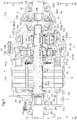
- FIG. 1 is an axial cross-sectional view of the vehicle driving apparatus 100
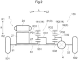
- FIG. 2 is a skeleton diagram of the vehicle driving apparatus 100.
- the vehicle driving apparatus 100 is a driving apparatus to be mounted on, for example, a hybrid vehicle that uses both an internal combustion engine and a rotating electrical machine as sources of driving force for a first wheel 501 and a second wheel 502, or an electric vehicle that uses a rotating electrical machine as a source of driving force for the first wheel 501 and the second wheel 502.
- the vehicle driving apparatus 100 includes a rotating electrical machine 2 only as a source of driving force for the first wheel 501 and the second wheel 502.
- drivingly coupled refers to a state where two rotating elements are coupled together such that driving force is transmittable therebetween. This includes a state where the two rotating elements are coupled in such a manner as to rotate together as a unit, or a state where the two rotating elements are coupled via one or two or more transmission members such that driving force is transmittable therebetween.
- the transmission members are various types of members that transmit rotation while maintaining or changing the rotation speed. Examples of the transmission members may include a shaft, a gear mechanism, a belt, and a chain.
- the transmission members may include an engagement device that selectively transmits rotation and driving force, such as a friction engagement device or an intermesh engagement device.
- the expression “drivingly coupled” refers to a state where three or more rotating elements of each of the devices are drivingly coupled without other rotating elements interposed therebetween.
- the vehicle driving apparatus 100 includes the following: a case 1; a rotating electrical machine 2 having a rotor shaft 27 for outputting driving force; the speed reduction device 3 including a planetary gear mechanism; and the differential gear device 4 that distributes the driving force from the rotating electrical machine 2 to a first drive shaft 51, drivingly coupled to an intermediate shaft 53, and a second drive shaft 52.
- the rotating electrical machine 2, the speed reduction device 3, the differential gear device 4, the first drive shaft 51, the second drive shaft 52, and the intermediate shaft 53 are coaxially disposed with respect to the rotor shaft 27 of the rotating electrical machine 2.
- the axial direction of the rotor shaft 27 of the rotating electrical machine 2 is equivalent to the direction of the axis of rotation of the vehicle driving apparatus 100
- the radial direction of the rotor shaft 27 of the rotating electrical machine 2 is equivalent to the radial direction of the vehicle driving apparatus 100.
- the axial direction of the rotor shaft 27 of the rotating electrical machine 2 is referred to as an axial direction L of the vehicle driving apparatus 100
- the radial direction of the rotor shaft 27 of the rotating electrical machine 2 is referred to as a radial direction R of the vehicle driving apparatus 100.
- a side toward the rotating electrical machine 2 with respect to the speed reduction device 3 is referred to as an axial first side L1
- a side toward the differential gear device 4 with respect to the speed reduction device 3 is referred to as an axial second side L2.
- an outer side away from the rotor shaft 27 is referred to as a radially outer side R1
- an inner side toward the rotor shaft 27 is referred to as a radially inner side R2.
- the vertical direction of the vehicle driving apparatus 100 being mounted on a vehicle is referred to as a vertical direction V.
- An upper side in the vertical direction is referred to as an upper side VI
- a lower side in the vertical direction is referred to as a lower side V2.
- the case 1 houses therein the rotating electrical machine 2, the speed reduction device 3, and the differential gear device 4. According to the present embodiment, the case 1 further houses therein a portion (an end potion on the axial second side L2) of the first drive shaft 51), a portion (an end portion on the axial first side L1) of the second drive shaft 52, and the intermediate shaft 53.
- the case 1 has the following: a case body 11 shaped like a tube with a bottom; a tube-shaped body cover 12 located to cover an opening of the case body 11 (on the axial second side L2) opposite to a bottom portion 11 a that is located at an end portion of the case body 11 on the axial first side L1; and a bottom cover 13 located on the axial first side L1 relative to the bottom portion 11a of the case body 11 to cover the bottom portion 11a.
- the case body 11 and the body cover 12 are fixed to each other by a fastening member (according to the present embodiment, a bolt).
- the case body 11 and the bottom cover 13 are fixed to each other by a fastening member (according to the present embodiment, a bolt).
- the rotating electrical machine 2 and a portion of the speed reduction device 3 are located in an inside space of the case body 11.
- Another portion of the speed reduction device 3 (a second planetary gear mechanism 32 that is described later), the differential gear device 4, and a portion (an end portion on the axial first side L1) of the second drive shaft 52 are located in an inside space of the body cover 12.
- a portion (an end portion on the axial second side L2) of the first drive shaft 51 is located in an inside space that is formed by the case body 11 and the bottom cover 13.
- the intermediate shaft 53 is located in an inside space formed by the case body 11, the body cover 12, and the bottom cover 13.
- the inside space of the case body 11 and the inside space of the body cover 12 form a single, continuous space. That is, within the case 1, the space housing the rotating electrical machine 2 and the space housing both the speed reduction device 3 and the differential gear device 4 communicate with each other.
- the case 1 further has a supporting member 14.
- the supporting member 14 includes a first supporting member 141 and a second supporting member 142.
- the first supporting member 141 is provided between the rotating electrical machine 2 and the speed reduction device 3 to extend along the radial direction R and a circumferential direction.
- the first supporting member 141 is formed continuously over the entire area in the circumferential direction.
- an end portion of the first supporting member 141 on the radially outer side R1 is integrally fixed to the case body 11 of the case 1 at one or multiple locations in the circumferential direction of the first supporting member 141.
- the second supporting member 142 is located on the axial second side L2 relative to the first supporting member 141 and is integrally fixed to the first supporting member 141.
- the second supporting member 142 is provided between the first planetary gear mechanism 31 and the second planetary gear mechanism 32 of the speed reduction device 3 to extend along the radial direction R and the circumferential direction.
- the second supporting member 142 is formed continuously over the entire area in the circumferential direction.
- the rotating electrical machine 2 is a source of driving force for the first wheel 501 and the second wheel 502.
- the rotating electrical machine 2 is a permanent-magnet-type rotating electrical machine and includes the following: a rotor 21 having permanent magnets 23 within a rotor core 22; a cylinder-shaped stator 24 having a stator coil 26 wound on a stator core 25; and the rotor shaft 27 coupled to the rotor core 22 in such a manner as to rotate together as a unit.
- the "cylinder-shaped” means that its rough shape is a cylinder as a whole even if it has a portion that is deformed a little (as well as other expressions hereinafter with "shaped” that are used to indicate shapes or the like).
- the rotor shaft 27 is coupled to the rotor core 22 on the radially inner side R2 of the rotor core 22 so that the rotor 21 and the rotor shaft 27 rotate together as a unit.
- the rotating electrical machine 2 is a permanent-magnet-type rotating electrical machine, but alternatively may be any other type of rotating electrical machine, such as an induction-type rotating electrical machine.
- the rotor shaft 27 is cylinder-shaped. A portion of the rotor shaft 27 that protrudes beyond the rotor core 22 in the axial direction L toward the axial first side L1 is rotatably supported by the case body 11 of the case 1 via a first rotor bearing 61. A portion of the rotor shaft 27 that protrudes beyond the rotor core 22 in the axial direction L toward the axial second side L2 is rotatably supported by the first supporting member 141 of the supporting member 14 via the second rotor bearing 62.
- the speed reduction device 3 is located between the rotating electrical machine 2 and the differential gear device 4 in the axial direction L, and transmits driving force to the differential gear device 4 while reducing the speed of rotation of the rotating electrical machine 2.
- the speed reduction device 3 includes the first planetary gear mechanism 31 and the second planetary gear mechanism 32.
- the first planetary gear mechanism 31 is a single-pinion-type planetary gear mechanism and includes a first sun gear S31, a first ring gear R31, a first carrier C31, and a first pinion gear P31.
- the first sun gear S31 is an input element of the first planetary gear mechanism 31 and is coupled to the rotor shaft 27 of the rotating electrical machine 2 in such a manner as to rotate together as a unit.
- the first ring gear R31 is supported on the first supporting member 141 of the supporting member 14 in such a manner as to be unrotatable in the circumferential direction.
- the first carrier C31 is an output element of the first planetary gear mechanism 31.
- the first pinion gear P31 is located in such a manner as to intermesh with both the first sun gear S31 and the first ring gear R31, and is rotatably supported by the first carrier C31.
- the first pinion gear P31 is structured in such a manner as to spin (rotate) on its own axis and to spin (revolve) around the first sun gear S31 (revolution). Although illustrations are omitted, multiple first pinion gears P31 are spaced from each other along the path of their revolution.
- the second planetary gear mechanism 32 is located adjacent to the first planetary gear mechanism 31 in the axial direction L and is located on the opposite side of the first planetary gear mechanism 31 from the rotating electrical machine 2. That is, in the axial direction L, from the axial first side L1 to the axial second side L2, the rotating electrical machine 2, the first planetary gear mechanism 31, and the second planetary gear mechanism 32 are disposed in the order mentioned.
- the second planetary gear mechanism 32 is a single-pinion-type planetary gear mechanism and includes a second sun gear S32, a second ring gear R32, a second carrier C32, and a second pinion gear P32.
- the second sun gear S32 is an input element of the second planetary gear mechanism 32.
- the second sun gear S32 is rotatably supported with respect to the intermediate shaft 53 via a plain bearing such as a bushing.
- the second sun gear S32 is coupled through spline engagement to the first carrier C31 of the first planetary gear mechanism 31.
- the second sun gear S32 and the first carrier C31 may be structured from a single component, or may be joined together by welding or the like into an integrated structure.
- the second ring gear R32 is supported on the second supporting member 142 of the supporting member 14 in such a manner as to be unrotatable in the circumferential direction.
- the second carrier C32 is an output element of the second planetary gear mechanism 32.
- an end portion of the second carrier C32 on the axial first side L1 is rotatably supported by the second supporting member 142 of the supporting member 14 via a first differential case bearing 66 at a location between the first planetary gear mechanism 31 and the second planetary gear mechanism 32 of the speed reduction device 3.
- the second pinion gear P32 is located in such a manner as to intermesh with both the second sun gear S32 and the second ring gear R32, and is rotatably supported by the second carrier C32.
- the second pinion gear P32 is structured in such a manner as to spin (rotate) on its own axis and to spin (revolve) around the second sun gear S32. Although illustrations are omitted, multiple second pinion gears P32 are spaced from each other along the path of their revolution.
- the differential gear device 4 distributes, to the first wheel 501 and the second wheel 502, the driving force transmitted from the rotating electrical machine 2 via the speed reduction device 3. According to the present embodiment, the differential gear device 4 distributes the driving force transmitted from the rotating electrical machine 2 via the speed reduction device 3, to the first wheel 501 and the second wheel 502 respectively via the first drive shaft 51 drivingly coupled to the intermediate shaft 53 and the second drive shaft 52.
- the differential gear device 4 has the following: a differential case D4 as an input element; a pinion shaft F4 supported by the differential case D4 in such a manner as to rotate as a unit with the differential case D4; a pair of differential pinion gears P4 rotatably supported with respect to the pinion shaft F4; and a first side gear B41 and a second side gear B42 as distribution output elements.
- the pair of differential pinion gears P4, the first side gear B41, and the second side gear B42, as described here, are all bevel gears. That is, the differential gear device 4 is a bevel-gear-type differential gear device.
- the differential case D4 is a hollow member and houses therein the pinion shaft F4, the pair of differential pinion gears P4, the first side gear B41, and the second side gear B42.
- the differential case D4 is formed unitarily with the second carrier C32 of the second planetary gear mechanism 32 of the speed reduction device 3, and the second carrier C32 is structured as part of the differential case D4.
- an end portion of the second carrier C32 on the axial first side L1 serves as a first supportable portion D4a of the differential case D4.
- the first supportable portion D4a is located between the first planetary gear mechanism 31 and the second planetary gear mechanism 32 in the axial direction L.
- the first supportable portion D4a is supported directly by the first differential case bearing 66 that is fixed to the case 1 via the supporting member 14.
- the first supporting member 141 of the supporting member 14 is integrally fixed to the case body 11 of the case 1, and the first supporting member 141 and the second supporting member 142 are integrally fixed to each other.
- the first supportable portion D4a is supported by the case body 11 of the case 1 via the first differential case bearing 66.
- the differential case D4 further has a second supportable portion D4b that is located on the side (the axial second side L2) opposite the first supportable portion D4a in the axial direction L.
- the second supportable portion D4b is formed to protrude beyond the second side gear B42 along the axial direction L toward the axial second side L2.
- the second supportable portion D4b is cylinder-shaped and is coaxial with both the first side gear B41 and the second side gear B42.
- the second supportable portion D4b is supported directly by a second differential case bearing 67 that is fixed to the body cover 12 of the case 1. That is, the second supportable portion D4b is rotatably supported by the body cover 12 of the case 1 via the second differential case bearing 67.
- the pinion shaft F4 is inserted through the pair of differential pinion gears P4 and rotatably supports them.
- the pinion shaft F4 is inserted in a through hole formed in the differential case D4 along the radial direction R and is retained to the differential case D4 by a stopper member 43.
- the pair of differential pinion gears P4 are attached to the pinion shaft F4 in such a manner as to face each other with a clearance therebetween in the radial direction R and are structured to rotate about the pinion shaft F4 in the inside space of the differential case D4.
- the first side gear B41 and the second side gear B42 are rotating elements after distribution in the differential gear device 4.
- the first side gear B41 and the second side gear B42 are spaced from each other in the axial direction L to face each other across the pinion shaft F4 and are structured to rotate in their respective circumferential directions in the inside space of the differential case D4.
- the first side gear B41 and the second side gear B42 intermesh with the pair of differential pinion gears P4.
- Splines for coupling to the intermediate shaft 53 are formed on the inner circumferential surface of the first side gear B41.
- Splines for coupling to the second drive shaft 52 are formed on the inner circumferential surface of the second side gear B42.
- the intermediate shaft 53 is a member that transmits, to the first drive shaft 51, the driving force from the rotating electrical machine 2 distributed by the differential gear device 4.
- the intermediate shaft 53 extends through the radially inner side R2 of the rotor shaft 27 of the rotating electrical machine 2 in the axial direction L.
- Splines for coupling to the first side gear B41 of the differential gear device 4 are formed on the outer circumferential surface of an end portion of the intermediate shaft 53 on the axial second side L2.
- the splines engage with the splines on the inner circumferential surface of the first side gear B41, and thus the intermediate shaft 53 and the first side gear B41 are coupled together in such a manner as to rotate together as a unit.
- a coupling portion 53a for coupling to the first drive shaft 51 is formed at an end portion of the intermediate shaft 53 on the axial first side L1.
- the coupling portion 53a extends into the inside space of the bottom cover 13 from a location in the inside space of the case body 11 that is on the axial first side L1 relative to the rotating electrical machine 2.
- the coupling portion 53a is cylinder-shaped and is coaxial with the remaining portion of the intermediate shaft 53 other than the coupling portion 53a.
- the coupling portion 53a has an outside diameter greater than the outside diameter of the remaining portion of the intermediate shaft 53 other than the coupling portion 53a.
- the coupling portion 53a is rotatably supported by the bottom cover 13 of the case 1 via a first output bearing 68 and is also rotatably supported by the bottom portion 11a of the case body 11 via a second output bearing 69.
- Splines for coupling to the first drive shaft 51 are formed on the inner circumferential surface of a portion of the coupling portion 53a on the axial second side L2.
- the first drive shaft 51 is drivingly coupled to the first wheel 501
- the second drive shaft 52 is drivingly coupled to the second wheel 502.
- the coupling portion 53a is provided at the end portion of the intermediate shaft 53 on the axial first side L1
- the first drive shaft 51 and the coupling portion 53a of the intermediate shaft 53 are spline-coupled together.
- a flange yoke instead of the coupling portion 53a may be provided at the end portion of the intermediate shaft 53 on the axial first side L1, and the flange yoke and the first drive shaft 51 may be bolted together.
- oil 7 is stored in the case 1 so as, for example, to cool the stator 24 of the rotating electrical machine 2 and to lubricate rotating members of the rotating electrical machine 2, such as the rotor 21.
- the space housing the rotating electrical machine 2 and the space housing the speed reduction device 3 and the differential gear device 4 in the case 1 communicate with each other.
- the oil 7 is stored in the space housing the rotating electrical machine 2 and in the space housing both the speed reduction device 3 and the differential gear device 4.
- the vehicle driving apparatus 100 includes an oil pump 8.
- the oil pump 8 functions as an "oil circulation mechanism” that circulates the oil 7 within the case 1.
- the oil pump 8 suctions the oil 7 stored in the case 1 and supplies the oil 7 to an oil passage that is formed on the case 1 or a member housed in the case 1. This oil passage communicates with at least one of the rotating electrical machine 2, the speed reduction device 3, and the differential gear device 4.
- an introduction oil passage 81 is formed in the bottom portion 11a of the case 1 along the radial direction R, and an in-shaft oil passage 82 is formed in the intermediate shaft 53 along the axial direction L.
- the introduction oil passage 81 and the in-shaft oil passage 82 communicate with each other through multiple connection oil passages 83 that are formed in the intermediate shaft 53 along the radial direction R.
- multiple distribution passages 84 are located in the intermediate shaft 53 and are spaced from each other in the axial direction L. Each of the distribution passages 84 is formed along the radial direction R from the in-shaft oil passage 82 to the outer circumferential surface of the intermediate shaft 53.
- the multiple distribution passages 84 include the following: three rotating-electrical-machine distribution oil passages 841 that communicate with the rotating electrical machine 2; a first mechanism distribution passage 842A; and a second mechanism distribution passage 842B. Further, in this example, an opening 53b communicating with the in-shaft oil passage 82 is formed in an end face of the intermediate shaft 53 on the axial second side L2. Thus, the in-shaft oil passage 82 communicates with the differential gear device 4.
- the oil pump 8 suctions the oil 7 stored in the case 1 and supplies the oil 7 to the introduction oil passage 81.
- the oil 7 supplied to the introduction oil passage 81 flows to the in-shaft oil passage 82 through the connection oil passages 83. Then, the oil 7 is supplied through the multiple distribution passages 84 to each of the members housed in the case 1, such as the rotating electrical machine 2.
- a portion of the oil 7 in the in-shaft oil passage 82 passes through the rotating-electrical-machine distribution oil passages 841 and then reaches the inner circumferential surface of the rotor shaft 27 of the rotating electrical machine 2.
- the rotor shaft 27 is cooled by the oil 7, and the rotor core 22 coupled to the rotor shaft 27 is cooled as well.
- the rotating-electrical-machine distribution oil passage 841 that is located furthest to the axial second side L2 is formed mainly to supply the oil 7 to the second rotor bearing 62 that rotatably supports the rotor shaft 27.
- a portion of the oil 7 in the in-shaft oil passage 82 flows through the first mechanism distribution passage 842A to a first in-mechanism oil passage 85A formed in both a first pinion shaft P31a and the first carrier C31 that rotatably support the first pinion gear P31 via a first bearing P31b. Then, the oil 7 flows to between the first pinion gear P31 and the first pinion shaft P31a through an opening formed in the outer circumferential surface of the first pinion shaft P31a, thus lubricating the first bearing P31b. After that, as the first pinion gear P31 rotates, the oil 7 is splashed around. Thus, the oil 7 is supplied to each member of the first planetary gear mechanism 31.
- the oil 7 in the in-shaft oil passage 82 flows through the second mechanism distribution passage 842B to a second in-mechanism oil passage 85B formed in both a second pinion shaft P32a and the second carrier C32 that rotatably support the second pinion gear P32 via a second bearing P32b. Then, the oil 7 flows to between the second pinion gear P32 and the second pinion shaft P32a through an opening formed in the outer circumferential surface of the second pinion shaft P32a, thus lubricating the second bearing P32b. After that, as the second pinion gear P32 rotates, the oil 7 is splashed around. Thus, the oil 7 is supplied to each member of the second planetary gear mechanism 32.
- a portion of the oil 7 in the in-shaft oil passage 82 flows into the differential case D4 of the differential gear device 4 through the opening 53b that is formed in the end face of the intermediate shaft 53 on the axial second side L2. Then, as the differential case D4 rotates, the oil 7 is supplied to each member of the differential gear device 4.
- An alternative structure may be such that the oil 7 in the case 1 is circulated by being scooped up with a scooping member that is structured from a rotating member having projections and recesses, such as a gear.
- the scooping member functions as the "oil circulation mechanism" that circulates the oil 7 within the case 1.
- the oil 7 scooped up may be supplied directly to a member to which the oil 7 is to be supplied, such as the rotating electrical machine 2, or may be supplied first to the introduction oil passage 81 and then supplied through the oil passages described above to the member to which the oil 7 is to be supplied.
- the scooping member may be provided to, for example, the carriers C31 and C32 of the speed reduction device 3 or the differential case D4 of the differential gear device 4.
- the scooping member may be provided instead of the oil pump 8 or in addition to the oil pump 8.
- an oil surface 7A that is the top surface of the oil 7 stored in the case 1 is positioned on the lower side V2 relative to the lower end of an inner circumferential surface 24a of the stator 24 of the rotating electrical machine 2 and is positioned on the upper side V1 relative to the lower end of an outer circumferential surface 24b of the stator 24. As illustrated in FIG.
- an oil surface position O_Lv that is the position of the oil surface 7A in the vertical direction V is positioned on the lower side V2 relative to a stator inner circumference lower end position I_Btm that is the position of the lower end of the inner circumferential surface 24a of the stator 24 and is also positioned on the upper side V1 relative to a stator outer circumference lower end position O_Btm that is the position of the lower end of the outer circumferential surface 24b of the stator 24.
- the “steady circulation state” herein is a state where circulation of the oil 7 in the case 1 is in a steady state.
- the “steady circulation state” is a state where the oil surface position O_Lv is stable while the oil pump 8 is operating.
- the scooping member is used to circulate the oil 7 in the case 1, it is a state where the oil surface position O_Lv is stable while the scooping member is rotating.
- the "steady circulation state” occurs while the vehicle is moving (while the rotating electrical machine 2 is rotating), but this does not exclude the possibility that the "steady circulation state” may occur while the vehicle (the rotating electrical machine 2, the wheels 501, 502) is at rest.
- the tilt of the vehicle in a direction (a vehicle longitudinal direction) perpendicular to the axial direction L is permissible
- the tilt of the vehicle in the axial direction L causes the oil surface position O_Lv in the case 1 to vary depending on the location in the axial direction L. Therefore, the oil surface position O_Lv in the steady circulation state described above is determined when the vehicle is not tilted at all in the axial direction L (a vehicle lateral direction).
- the oil surface position O_Lv in the steady circulation state described above is determined when there are no such fluctuations in the oil surface 7Adue to vibration, acceleration, or deceleration of the vehicle.
- the oil surface 7A of the oil 7 stored in the case 1 be positioned on the lower side V2 relative to the lower end of the path of revolution of the pinion gear of the planetary gear mechanism of the speed reduction device 3.
- the inside diameter of the stator 24 is equal to or greater than the outside diameter of the path of revolution of the pinion gear of the planetary gear mechanism of the speed reduction device 3.
- the oil surface 7A is positioned on the lower side V2 relative to the lower end of the inner circumferential surface 24a of the stator 24 of the rotating electrical machine 2.
- the oil surface 7A is naturally positioned on the lower side V2 relative to the lower end of the path of revolution of the pinion gear.
- the speed reduction device 3 includes multiple planetary gear mechanisms, it is preferable that in the steady circulation state, the oil surface 7A be positioned on the lower side V2 relative to the lower end of the path of revolution of the planetary gear mechanism that is located furthest to the lower side V2 of all the lower ends of the paths of revolution of the multiple planetary gear mechanisms.
- the speed reduction device 3 includes two planetary gear mechanisms, namely, the first planetary gear mechanism 31 and the second planetary gear mechanism 32. As illustrated in FIG.
- a first pinion lower end position P1_Btm that is the position of the lower end of the path of revolution of the first pinion gear P31 of the first planetary gear mechanism 31 is set equal to a second pinion lower end position P2_Btm that is the position of the lower end of the path of revolution of the second pinion gear P32 of the second planetary gear mechanism 32.
- the oil surface position O_Lv be positioned on the lower side V2 relative to both the first pinion lower end position P1_Btm and the second pinion lower end position P2_Btm.
- the oil surface 7A of the oil 7 stored in the case 1 may be positioned on the lower side V2 relative to the lower end of the differential gear device 4.
- the lower end of the differential gear device 4 refers to the lower end of a portion of the differential gear device 4, which rotates as a whole, when the portion protruding furthest to the radially outer side R1 is at its lowest position.
- the lower end of the differential gear device 4 is the lower end of the pinion shaft F4 that is in an attitude extending in the vertical direction V.
- the oil surface position O_Lv is positioned on the lower side V2 relative to a first differential lower end position D1_Btm that is the position of the lower end of the differential gear device 4.
- a vehicle driving apparatus (100) includes the following: a rotating electrical machine (2) that acts as a source of driving force for a first wheel (501) and a second wheel (502); a speed reduction device (3) that reduces the speed of rotation of the rotating electrical machine (2); a differential gear device (4) that distributes, to the first wheel (501) and the second wheel (502), the driving force transmitted from the rotating electrical machine (2) via the speed reduction device (3); a case (1) that houses the rotating electrical machine (2), the speed reduction device (3), and the differential gear device (4); and an oil circulation mechanism.
- the rotating electrical machine (2) has a cylinder-shaped stator (24) and a rotor (21) that is located on a radially inner side (R2) relative to the stator (24).
- the speed reduction device (3) and the differential gear device (4) are located coaxial with the rotating electrical machine (2).
- Oil (7) is stored in the case (1).
- the oil circulation mechanism circulates the oil (7) within the case (1).
- an oil surface (7A) that is the top surface of the oil (7) is positioned on a lower side (V2) relative to a lower end of an inner circumferential surface (24a) of the stator (24) and is positioned on an upper side (V1) relative to a lower end of an outer circumferential surface (24b) of the stator (24).
- the speed reduction device (3) include a planetary gear mechanism (31, 32) having a sun gear (S31, S32), a pinion gear (P31, P32) that revolves around the sun gear (S31, S32), and a ring gear (R31, R32) fixed with respect to the case (1), and that in the steady circulation state, the oil surface (7A) be positioned on the lower side (V2) relative to a lower end of a path of revolution of the pinion gear (P31, P32).
- a planetary gear mechanism 31, 32 having a sun gear (S31, S32), a pinion gear (P31, P32) that revolves around the sun gear (S31, S32), and a ring gear (R31, R32) fixed with respect to the case (1), and that in the steady circulation state, the oil surface (7A) be positioned on the lower side (V2) relative to a lower end of a path of revolution of the pinion gear (P31, P32).
- the pinion gear (P31, P32) of the speed reduction device (3) which is a rotating member, is not in contact with the oil surface (7A).
- the pinion gear (P31, P32) of the speed reduction device (3) rotates faster than other rotating members in the case (1), it is possible to effectively reduce the resistance of the oil (7) to stirring by rotating members.
- the oil surface (7A) may be preferably positioned on the lower side (V2) relative to a lower end of the differential gear device (4).
- an inside diameter of the stator (24) may be preferably equal to or greater than an outside diameter of the path of revolution of the pinion gear (P31, P32).
- the lower end of the path of revolution of the pinion gear (P31, P32) of the speed reduction device (3) is in the same position in the vertical direction (V) as the lower end of the inner circumferential surface (24a) of the stator (24) or is positioned on the upper side (V1) relative to the lower end of the inner circumferential surface (24a) of the stator (24).
- setting the position of the oil surface (7A) to the lower side (V2) relative to the inner circumferential surface (24a) of the stator (24) allows the pinion gear (P31, P32) of the speed reduction device (3) to avoid contact with the oil surface (7A). Therefore, it is possible to reduce resistance of the oil (7) to stirring by the rotor (21) of the rotating electrical machine (2) and by the pinion gear (P31, P32) of the speed reduction device (3).
- the oil circulation mechanism be an oil pump (8), and that the oil pump (8) suction the oil (7) stored in the case (1) and supply the oil (7) to an oil passage (81, 82, 83, 84) that is formed on the case (1) or a member housed in the case (1).
- the oil passage (81, 82, 83, 84) may preferably communicate with at least one of the rotating electrical machine (2), the speed reduction device (3), and the differential gear device (4).
- the speed reduction device (3) may be preferably located between the rotating electrical machine (2) and the differential gear device (4) in an axial direction (L).
- this structure it is possible to simplify the arrangement of members housed in the case (1).
- this structure facilitates the supply of the oil (7) to the members housed in the case (1).
- the technique according to the present disclosure is applicable to a vehicle driving apparatus including the following: a rotating electrical machine that acts as a source of driving force for a first wheel and a second wheel; a speed reduction device that reduces the speed of rotation of the rotating electrical machine; a differential gear device that distributes, to the first wheel and the second wheel, the driving force transmitted from the rotating electrical machine via the speed reduction device; and a case that houses them.
Landscapes
- Engineering & Computer Science (AREA)
- General Engineering & Computer Science (AREA)
- Mechanical Engineering (AREA)
- Power Engineering (AREA)
- Transportation (AREA)
- Combustion & Propulsion (AREA)
- Chemical & Material Sciences (AREA)
- General Details Of Gearings (AREA)
- Retarders (AREA)
- Connection Of Motors, Electrical Generators, Mechanical Devices, And The Like (AREA)
- Arrangement Or Mounting Of Propulsion Units For Vehicles (AREA)
- Electric Propulsion And Braking For Vehicles (AREA)
- Motor Or Generator Cooling System (AREA)
- Motor Power Transmission Devices (AREA)
Abstract
Description
- The present invention relates to a vehicle driving apparatus including the following: a rotating electrical machine that acts as a source of driving force for a first wheel and a second wheel; a speed reduction device that reduces the speed of rotation of the rotating electrical machine; a differential gear device that distributes, to the first wheel and the second wheel, the driving force transmitted from the rotating electrical machine via the speed reduction device; and a case that houses them.
-
Patent Document 1 below discloses a vehicle driving apparatus configured such that oil is supplied by an oil pump to a rotating electrical machine, a speed reduction device, and a differential gear device that are located in a case, so as to lubricate and cool them. - In this type of vehicle driving apparatus, setting an appropriate amount of oil in a case is the issue. For example, a lack of oil stored in an inside space of the case may result in insufficient cooling of a stator of a rotating electrical machine, insufficient lubrication of a rotating member of the rotating electrical machine, such as a rotor, etc. In contrast, an excess amount of oil stored in the inside space of the case may increase resistance of oil to stirring by the rotating member of the rotating electrical machine, such as a rotor.
- Patent Document 1: Japanese Unexamined Patent Application Publication No.
H8-48164 JP 8-48164 A FIG. 1 ) - Therefore, it is desired to achieve a vehicle driving apparatus that ensures an appropriate amount of oil in a case when the oil is stored in a space located in the case and housing a rotating electrical machine.
- In view of the above, a vehicle driving apparatus includes the following characteristic structure: a rotating electrical machine that acts as a source of driving force for a first wheel and a second wheel; a speed reduction device that reduces the speed of rotation of the rotating electrical machine; a differential gear device that distributes, to the first wheel and the second wheel, the driving force transmitted from the rotating electrical machine via the speed reduction device; a case that houses the rotating electrical machine, the speed reduction device, and the differential gear device; and an oil circulation mechanism. The rotating electrical machine has a cylinder-shaped stator and a rotor that is located on a radially inner side relative to the stator. The speed reduction device and the differential gear device are located coaxial with the rotating electrical machine. Oil is stored in the case. The oil circulation mechanism circulates the oil within the case. In a steady circulation state where circulation of the oil is in a steady state, an oil surface that is the top surface of the oil is positioned on a lower side relative to a lower end of an inner circumferential surface of the stator and is positioned on an upper side relative to a lower end of an outer circumferential surface of the stator.
- According to this characteristic structure, in the steady circulation state where the position of the oil surface is stable, it is possible to ensure a relatively large amount of the oil that allows the stator to be partially submerged in the oil surface while keeping the rotor, which is a rotating member of the rotating electrical machine, out of contact with the oil surface. Thus, when the oil is stored in a space located in the case and housing the rotating electrical machine, it is possible to reduce resistance of the oil to stirring by the rotor of the rotating electrical machine while ensuring an appropriate amount of the oil needed to cool the stator of the rotating electrical machine, to lubricate a rotating member such as the rotor, etc.
-
- [
FIG. 1] FIG. 1 is an axial cross-sectional view of a vehicle driving apparatus according to an embodiment. - [
FIG. 2] FIG. 2 is a skeleton diagram of the vehicle driving apparatus according to the embodiment. - [
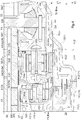
FIG. 3] FIG. 3 is an axial cross-sectional view of a main portion of the vehicle driving apparatus according to the embodiment. - [
FIG. 4] FIG. 4 is an axial cross-sectional view of a main portion of the vehicle driving apparatus according to the embodiment. - [
FIG. 5] FIG. 5 is an axial cross-sectional view of a main portion of a vehicle driving apparatus including a differential gear device according to another embodiment. - [
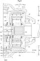
FIG. 6] FIG. 6 is an axial cross-sectional view of a vehicle driving apparatus according to another embodiment. - A
vehicle driving apparatus 100 according an embodiment of a vehicle driving apparatus is described below with reference to the drawings.FIG. 1 is an axial cross-sectional view of thevehicle driving apparatus 100, andFIG. 2 is a skeleton diagram of thevehicle driving apparatus 100. Thevehicle driving apparatus 100 is a driving apparatus to be mounted on, for example, a hybrid vehicle that uses both an internal combustion engine and a rotating electrical machine as sources of driving force for afirst wheel 501 and asecond wheel 502, or an electric vehicle that uses a rotating electrical machine as a source of driving force for thefirst wheel 501 and thesecond wheel 502. As illustrated inFIG. 1 andFIG. 2 , thevehicle driving apparatus 100 includes a rotatingelectrical machine 2 only as a source of driving force for thefirst wheel 501 and thesecond wheel 502. In the case of four-wheel vehicles with two-wheel drive, this makes it possible to achieve electric vehicles. On the other hand, in the case of four-wheel vehicles with four-wheel drive, it is possible to achieve hybrid vehicles by driving the other two wheels using driving force of an internal combustion engine. Undoubtedly, in the case of four-wheel vehicles with four-wheel drive, it is possible to archive electric vehicles with four-wheel drive by using thevehicle driving apparatus 100 according to the present embodiment also for the other two wheels. - In the description below, "drivingly coupled" refers to a state where two rotating elements are coupled together such that driving force is transmittable therebetween. This includes a state where the two rotating elements are coupled in such a manner as to rotate together as a unit, or a state where the two rotating elements are coupled via one or two or more transmission members such that driving force is transmittable therebetween. The transmission members are various types of members that transmit rotation while maintaining or changing the rotation speed. Examples of the transmission members may include a shaft, a gear mechanism, a belt, and a chain. The transmission members may include an engagement device that selectively transmits rotation and driving force, such as a friction engagement device or an intermesh engagement device. However, as for rotating elements of a
speed reduction device 3 and adifferential gear device 4 that are described below, the expression "drivingly coupled" refers to a state where three or more rotating elements of each of the devices are drivingly coupled without other rotating elements interposed therebetween. - As illustrated in
FIG. 1 andFIG. 2 , thevehicle driving apparatus 100 includes the following: acase 1; a rotatingelectrical machine 2 having arotor shaft 27 for outputting driving force; thespeed reduction device 3 including a planetary gear mechanism; and thedifferential gear device 4 that distributes the driving force from the rotatingelectrical machine 2 to afirst drive shaft 51, drivingly coupled to anintermediate shaft 53, and asecond drive shaft 52. - In the
vehicle driving apparatus 100, the rotatingelectrical machine 2, thespeed reduction device 3, thedifferential gear device 4, thefirst drive shaft 51, thesecond drive shaft 52, and theintermediate shaft 53 are coaxially disposed with respect to therotor shaft 27 of the rotatingelectrical machine 2. Thus, the axial direction of therotor shaft 27 of the rotatingelectrical machine 2 is equivalent to the direction of the axis of rotation of thevehicle driving apparatus 100, and the radial direction of therotor shaft 27 of the rotatingelectrical machine 2 is equivalent to the radial direction of thevehicle driving apparatus 100. Therefore, the axial direction of therotor shaft 27 of the rotatingelectrical machine 2 is referred to as an axial direction L of thevehicle driving apparatus 100, and the radial direction of therotor shaft 27 of the rotatingelectrical machine 2 is referred to as a radial direction R of thevehicle driving apparatus 100. Further, in the axial direction L, a side toward the rotatingelectrical machine 2 with respect to thespeed reduction device 3 is referred to as an axial first side L1, and a side toward thedifferential gear device 4 with respect to thespeed reduction device 3 is referred to as an axial second side L2. Further, in the radial direction R, an outer side away from therotor shaft 27 is referred to as a radially outer side R1, and an inner side toward therotor shaft 27 is referred to as a radially inner side R2. Further, the vertical direction of thevehicle driving apparatus 100 being mounted on a vehicle is referred to as a vertical direction V. An upper side in the vertical direction is referred to as an upper side VI, and a lower side in the vertical direction is referred to as a lower side V2. - The
case 1 houses therein the rotatingelectrical machine 2, thespeed reduction device 3, and thedifferential gear device 4. According to the present embodiment, thecase 1 further houses therein a portion (an end potion on the axial second side L2) of the first drive shaft 51), a portion (an end portion on the axial first side L1) of thesecond drive shaft 52, and theintermediate shaft 53. Thecase 1 has the following: acase body 11 shaped like a tube with a bottom; a tube-shaped body cover 12 located to cover an opening of the case body 11 (on the axial second side L2) opposite to abottom portion 11 a that is located at an end portion of thecase body 11 on the axial first side L1; and abottom cover 13 located on the axial first side L1 relative to thebottom portion 11a of thecase body 11 to cover thebottom portion 11a. Thecase body 11 and thebody cover 12 are fixed to each other by a fastening member (according to the present embodiment, a bolt). Thecase body 11 and thebottom cover 13 are fixed to each other by a fastening member (according to the present embodiment, a bolt). - The rotating
electrical machine 2 and a portion of the speed reduction device 3 (a firstplanetary gear mechanism 31 that is described later) are located in an inside space of thecase body 11. Another portion of the speed reduction device 3 (a secondplanetary gear mechanism 32 that is described later), thedifferential gear device 4, and a portion (an end portion on the axial first side L1) of thesecond drive shaft 52 are located in an inside space of thebody cover 12. A portion (an end portion on the axial second side L2) of thefirst drive shaft 51 is located in an inside space that is formed by thecase body 11 and thebottom cover 13. Theintermediate shaft 53 is located in an inside space formed by thecase body 11, thebody cover 12, and thebottom cover 13. According to the present embodiment, when the rotatingelectrical machine 2, thespeed reduction device 3, and thedifferential gear device 4 are housed in thecase 1, the inside space of thecase body 11 and the inside space of the body cover 12 form a single, continuous space. That is, within thecase 1, the space housing the rotatingelectrical machine 2 and the space housing both thespeed reduction device 3 and thedifferential gear device 4 communicate with each other. - The
case 1 further has a supportingmember 14. According to the present embodiment, the supportingmember 14 includes a first supportingmember 141 and a second supportingmember 142. The first supportingmember 141 is provided between the rotatingelectrical machine 2 and thespeed reduction device 3 to extend along the radial direction R and a circumferential direction. In this example, the first supportingmember 141 is formed continuously over the entire area in the circumferential direction. Although illustrations are omitted, an end portion of the first supportingmember 141 on the radially outer side R1 is integrally fixed to thecase body 11 of thecase 1 at one or multiple locations in the circumferential direction of the first supportingmember 141. The second supportingmember 142 is located on the axial second side L2 relative to the first supportingmember 141 and is integrally fixed to the first supportingmember 141. The second supportingmember 142 is provided between the firstplanetary gear mechanism 31 and the secondplanetary gear mechanism 32 of thespeed reduction device 3 to extend along the radial direction R and the circumferential direction. In this example, the second supportingmember 142 is formed continuously over the entire area in the circumferential direction. - The rotating
electrical machine 2, as described above, is a source of driving force for thefirst wheel 501 and thesecond wheel 502. The rotatingelectrical machine 2 is a permanent-magnet-type rotating electrical machine and includes the following: arotor 21 havingpermanent magnets 23 within arotor core 22; a cylinder-shapedstator 24 having astator coil 26 wound on astator core 25; and therotor shaft 27 coupled to therotor core 22 in such a manner as to rotate together as a unit. The "cylinder-shaped" means that its rough shape is a cylinder as a whole even if it has a portion that is deformed a little (as well as other expressions hereinafter with "shaped" that are used to indicate shapes or the like). Therotor shaft 27 is coupled to therotor core 22 on the radially inner side R2 of therotor core 22 so that therotor 21 and therotor shaft 27 rotate together as a unit. According to the present embodiment, the rotatingelectrical machine 2 is a permanent-magnet-type rotating electrical machine, but alternatively may be any other type of rotating electrical machine, such as an induction-type rotating electrical machine. - The
rotor shaft 27 is cylinder-shaped. A portion of therotor shaft 27 that protrudes beyond therotor core 22 in the axial direction L toward the axial first side L1 is rotatably supported by thecase body 11 of thecase 1 via afirst rotor bearing 61. A portion of therotor shaft 27 that protrudes beyond therotor core 22 in the axial direction L toward the axial second side L2 is rotatably supported by the first supportingmember 141 of the supportingmember 14 via the second rotor bearing 62. - The
speed reduction device 3 is located between the rotatingelectrical machine 2 and thedifferential gear device 4 in the axial direction L, and transmits driving force to thedifferential gear device 4 while reducing the speed of rotation of the rotatingelectrical machine 2. According to the present embodiment, thespeed reduction device 3 includes the firstplanetary gear mechanism 31 and the secondplanetary gear mechanism 32. - The first
planetary gear mechanism 31 is a single-pinion-type planetary gear mechanism and includes a first sun gear S31, a first ring gear R31, a first carrier C31, and a first pinion gear P31. The first sun gear S31 is an input element of the firstplanetary gear mechanism 31 and is coupled to therotor shaft 27 of the rotatingelectrical machine 2 in such a manner as to rotate together as a unit. The first ring gear R31 is supported on the first supportingmember 141 of the supportingmember 14 in such a manner as to be unrotatable in the circumferential direction. The first carrier C31 is an output element of the firstplanetary gear mechanism 31. The first pinion gear P31 is located in such a manner as to intermesh with both the first sun gear S31 and the first ring gear R31, and is rotatably supported by the first carrier C31. The first pinion gear P31 is structured in such a manner as to spin (rotate) on its own axis and to spin (revolve) around the first sun gear S31 (revolution). Although illustrations are omitted, multiple first pinion gears P31 are spaced from each other along the path of their revolution. - The second
planetary gear mechanism 32 is located adjacent to the firstplanetary gear mechanism 31 in the axial direction L and is located on the opposite side of the firstplanetary gear mechanism 31 from the rotatingelectrical machine 2. That is, in the axial direction L, from the axial first side L1 to the axial second side L2, the rotatingelectrical machine 2, the firstplanetary gear mechanism 31, and the secondplanetary gear mechanism 32 are disposed in the order mentioned. The secondplanetary gear mechanism 32 is a single-pinion-type planetary gear mechanism and includes a second sun gear S32, a second ring gear R32, a second carrier C32, and a second pinion gear P32. - The second sun gear S32 is an input element of the second
planetary gear mechanism 32. According to the present embodiment, the second sun gear S32 is rotatably supported with respect to theintermediate shaft 53 via a plain bearing such as a bushing. Further, according to the present embodiment, the second sun gear S32 is coupled through spline engagement to the first carrier C31 of the firstplanetary gear mechanism 31. The second sun gear S32 and the first carrier C31 may be structured from a single component, or may be joined together by welding or the like into an integrated structure. The second ring gear R32 is supported on the second supportingmember 142 of the supportingmember 14 in such a manner as to be unrotatable in the circumferential direction. The second carrier C32 is an output element of the secondplanetary gear mechanism 32. According to the present embodiment, an end portion of the second carrier C32 on the axial first side L1 is rotatably supported by the second supportingmember 142 of the supportingmember 14 via a first differential case bearing 66 at a location between the firstplanetary gear mechanism 31 and the secondplanetary gear mechanism 32 of thespeed reduction device 3. The second pinion gear P32 is located in such a manner as to intermesh with both the second sun gear S32 and the second ring gear R32, and is rotatably supported by the second carrier C32. The second pinion gear P32 is structured in such a manner as to spin (rotate) on its own axis and to spin (revolve) around the second sun gear S32. Although illustrations are omitted, multiple second pinion gears P32 are spaced from each other along the path of their revolution. - The
differential gear device 4 distributes, to thefirst wheel 501 and thesecond wheel 502, the driving force transmitted from the rotatingelectrical machine 2 via thespeed reduction device 3. According to the present embodiment, thedifferential gear device 4 distributes the driving force transmitted from the rotatingelectrical machine 2 via thespeed reduction device 3, to thefirst wheel 501 and thesecond wheel 502 respectively via thefirst drive shaft 51 drivingly coupled to theintermediate shaft 53 and thesecond drive shaft 52. Specifically, thedifferential gear device 4 has the following: a differential case D4 as an input element; a pinion shaft F4 supported by the differential case D4 in such a manner as to rotate as a unit with the differential case D4; a pair of differential pinion gears P4 rotatably supported with respect to the pinion shaft F4; and a first side gear B41 and a second side gear B42 as distribution output elements. The pair of differential pinion gears P4, the first side gear B41, and the second side gear B42, as described here, are all bevel gears. That is, thedifferential gear device 4 is a bevel-gear-type differential gear device. - The differential case D4 is a hollow member and houses therein the pinion shaft F4, the pair of differential pinion gears P4, the first side gear B41, and the second side gear B42. According to the present embodiment, the differential case D4 is formed unitarily with the second carrier C32 of the second
planetary gear mechanism 32 of thespeed reduction device 3, and the second carrier C32 is structured as part of the differential case D4. Thus, according to the present embodiment, an end portion of the second carrier C32 on the axial first side L1 serves as a first supportable portion D4a of the differential case D4. The first supportable portion D4a is located between the firstplanetary gear mechanism 31 and the secondplanetary gear mechanism 32 in the axial direction L. The first supportable portion D4a is supported directly by the first differential case bearing 66 that is fixed to thecase 1 via the supportingmember 14. As already described, the first supportingmember 141 of the supportingmember 14 is integrally fixed to thecase body 11 of thecase 1, and the first supportingmember 141 and the second supportingmember 142 are integrally fixed to each other. Thus, the first supportable portion D4a is supported by thecase body 11 of thecase 1 via the first differential case bearing 66. - The differential case D4 further has a second supportable portion D4b that is located on the side (the axial second side L2) opposite the first supportable portion D4a in the axial direction L. The second supportable portion D4b is formed to protrude beyond the second side gear B42 along the axial direction L toward the axial second side L2. The second supportable portion D4b is cylinder-shaped and is coaxial with both the first side gear B41 and the second side gear B42. The second supportable portion D4b is supported directly by a second differential case bearing 67 that is fixed to the
body cover 12 of thecase 1. That is, the second supportable portion D4b is rotatably supported by thebody cover 12 of thecase 1 via the second differential case bearing 67. - The pinion shaft F4 is inserted through the pair of differential pinion gears P4 and rotatably supports them. The pinion shaft F4 is inserted in a through hole formed in the differential case D4 along the radial direction R and is retained to the differential case D4 by a
stopper member 43. - The pair of differential pinion gears P4 are attached to the pinion shaft F4 in such a manner as to face each other with a clearance therebetween in the radial direction R and are structured to rotate about the pinion shaft F4 in the inside space of the differential case D4.
- The first side gear B41 and the second side gear B42 are rotating elements after distribution in the
differential gear device 4. The first side gear B41 and the second side gear B42 are spaced from each other in the axial direction L to face each other across the pinion shaft F4 and are structured to rotate in their respective circumferential directions in the inside space of the differential case D4. The first side gear B41 and the second side gear B42 intermesh with the pair of differential pinion gears P4. Splines for coupling to theintermediate shaft 53 are formed on the inner circumferential surface of the first side gear B41. Splines for coupling to thesecond drive shaft 52 are formed on the inner circumferential surface of the second side gear B42. - The
intermediate shaft 53 is a member that transmits, to thefirst drive shaft 51, the driving force from the rotatingelectrical machine 2 distributed by thedifferential gear device 4. Theintermediate shaft 53 extends through the radially inner side R2 of therotor shaft 27 of the rotatingelectrical machine 2 in the axial direction L. Splines for coupling to the first side gear B41 of thedifferential gear device 4 are formed on the outer circumferential surface of an end portion of theintermediate shaft 53 on the axial second side L2. The splines engage with the splines on the inner circumferential surface of the first side gear B41, and thus theintermediate shaft 53 and the first side gear B41 are coupled together in such a manner as to rotate together as a unit. Acoupling portion 53a for coupling to thefirst drive shaft 51 is formed at an end portion of theintermediate shaft 53 on the axial first side L1. - The
coupling portion 53a extends into the inside space of thebottom cover 13 from a location in the inside space of thecase body 11 that is on the axial first side L1 relative to the rotatingelectrical machine 2. Thecoupling portion 53a is cylinder-shaped and is coaxial with the remaining portion of theintermediate shaft 53 other than thecoupling portion 53a. Thecoupling portion 53a has an outside diameter greater than the outside diameter of the remaining portion of theintermediate shaft 53 other than thecoupling portion 53a. Thecoupling portion 53a is rotatably supported by thebottom cover 13 of thecase 1 via afirst output bearing 68 and is also rotatably supported by thebottom portion 11a of thecase body 11 via asecond output bearing 69. Splines for coupling to thefirst drive shaft 51 are formed on the inner circumferential surface of a portion of thecoupling portion 53a on the axial second side L2. - The
first drive shaft 51 is drivingly coupled to thefirst wheel 501, and thesecond drive shaft 52 is drivingly coupled to thesecond wheel 502. According to the present embodiment, thecoupling portion 53a is provided at the end portion of theintermediate shaft 53 on the axial first side L1, and thefirst drive shaft 51 and thecoupling portion 53a of theintermediate shaft 53 are spline-coupled together. However, without being limited to such a structure, for example, a flange yoke instead of thecoupling portion 53a may be provided at the end portion of theintermediate shaft 53 on the axial first side L1, and the flange yoke and thefirst drive shaft 51 may be bolted together. - In the
vehicle driving apparatus 100 structured as described above,oil 7 is stored in thecase 1 so as, for example, to cool thestator 24 of the rotatingelectrical machine 2 and to lubricate rotating members of the rotatingelectrical machine 2, such as therotor 21. As already described, according to the present embodiment, the space housing the rotatingelectrical machine 2 and the space housing thespeed reduction device 3 and thedifferential gear device 4 in thecase 1 communicate with each other. Thus, theoil 7 is stored in the space housing the rotatingelectrical machine 2 and in the space housing both thespeed reduction device 3 and thedifferential gear device 4. - According to the present embodiment, the
vehicle driving apparatus 100 includes anoil pump 8. Theoil pump 8 functions as an "oil circulation mechanism" that circulates theoil 7 within thecase 1. According to the present embodiment, theoil pump 8 suctions theoil 7 stored in thecase 1 and supplies theoil 7 to an oil passage that is formed on thecase 1 or a member housed in thecase 1. This oil passage communicates with at least one of the rotatingelectrical machine 2, thespeed reduction device 3, and thedifferential gear device 4. - According to the present embodiment, an
introduction oil passage 81 is formed in thebottom portion 11a of thecase 1 along the radial direction R, and an in-shaft oil passage 82 is formed in theintermediate shaft 53 along the axial direction L. Theintroduction oil passage 81 and the in-shaft oil passage 82 communicate with each other through multipleconnection oil passages 83 that are formed in theintermediate shaft 53 along the radial direction R. Further,multiple distribution passages 84 are located in theintermediate shaft 53 and are spaced from each other in the axial direction L. Each of thedistribution passages 84 is formed along the radial direction R from the in-shaft oil passage 82 to the outer circumferential surface of theintermediate shaft 53. In this example, themultiple distribution passages 84 include the following: three rotating-electrical-machinedistribution oil passages 841 that communicate with the rotatingelectrical machine 2; a firstmechanism distribution passage 842A; and a secondmechanism distribution passage 842B. Further, in this example, anopening 53b communicating with the in-shaft oil passage 82 is formed in an end face of theintermediate shaft 53 on the axial second side L2. Thus, the in-shaft oil passage 82 communicates with thedifferential gear device 4. - According to the present embodiment, the
oil pump 8 suctions theoil 7 stored in thecase 1 and supplies theoil 7 to theintroduction oil passage 81. Theoil 7 supplied to theintroduction oil passage 81 flows to the in-shaft oil passage 82 through theconnection oil passages 83. Then, theoil 7 is supplied through themultiple distribution passages 84 to each of the members housed in thecase 1, such as the rotatingelectrical machine 2. - In this example, a portion of the
oil 7 in the in-shaft oil passage 82 passes through the rotating-electrical-machinedistribution oil passages 841 and then reaches the inner circumferential surface of therotor shaft 27 of the rotatingelectrical machine 2. As a result, therotor shaft 27 is cooled by theoil 7, and therotor core 22 coupled to therotor shaft 27 is cooled as well. Further, in this example, out of all the three rotating-electrical-machinedistribution oil passages 841, the rotating-electrical-machinedistribution oil passage 841 that is located furthest to the axial second side L2 is formed mainly to supply theoil 7 to the second rotor bearing 62 that rotatably supports therotor shaft 27. That is, a portion of theoil 7 reaching the inner circumferential surface of therotor shaft 27 flows to the second rotor bearing 62 through an oil passage that is formed to penetrate therotor shaft 27 in the radial direction R, thus lubricating the second rotor bearing 62. - Further, in this example, a portion of the
oil 7 in the in-shaft oil passage 82 flows through the firstmechanism distribution passage 842A to a first in-mechanism oil passage 85A formed in both a first pinion shaft P31a and the first carrier C31 that rotatably support the first pinion gear P31 via a first bearing P31b. Then, theoil 7 flows to between the first pinion gear P31 and the first pinion shaft P31a through an opening formed in the outer circumferential surface of the first pinion shaft P31a, thus lubricating the first bearing P31b. After that, as the first pinion gear P31 rotates, theoil 7 is splashed around. Thus, theoil 7 is supplied to each member of the firstplanetary gear mechanism 31. Furthermore, in this example, theoil 7 in the in-shaft oil passage 82 flows through the secondmechanism distribution passage 842B to a second in-mechanism oil passage 85B formed in both a second pinion shaft P32a and the second carrier C32 that rotatably support the second pinion gear P32 via a second bearing P32b. Then, theoil 7 flows to between the second pinion gear P32 and the second pinion shaft P32a through an opening formed in the outer circumferential surface of the second pinion shaft P32a, thus lubricating the second bearing P32b. After that, as the second pinion gear P32 rotates, theoil 7 is splashed around. Thus, theoil 7 is supplied to each member of the secondplanetary gear mechanism 32. - Further, in this example, a portion of the
oil 7 in the in-shaft oil passage 82 flows into the differential case D4 of thedifferential gear device 4 through theopening 53b that is formed in the end face of theintermediate shaft 53 on the axial second side L2. Then, as the differential case D4 rotates, theoil 7 is supplied to each member of thedifferential gear device 4. - An alternative structure may be such that the
oil 7 in thecase 1 is circulated by being scooped up with a scooping member that is structured from a rotating member having projections and recesses, such as a gear. In this structure, the scooping member functions as the "oil circulation mechanism" that circulates theoil 7 within thecase 1. In this case, theoil 7 scooped up may be supplied directly to a member to which theoil 7 is to be supplied, such as the rotatingelectrical machine 2, or may be supplied first to theintroduction oil passage 81 and then supplied through the oil passages described above to the member to which theoil 7 is to be supplied. The scooping member may be provided to, for example, the carriers C31 and C32 of thespeed reduction device 3 or the differential case D4 of thedifferential gear device 4. The scooping member may be provided instead of theoil pump 8 or in addition to theoil pump 8. - In a steady circulation state where circulation of the
oil 7 in thecase 1 is in a steady state, anoil surface 7A that is the top surface of theoil 7 stored in thecase 1 is positioned on the lower side V2 relative to the lower end of an innercircumferential surface 24a of thestator 24 of the rotatingelectrical machine 2 and is positioned on the upper side V1 relative to the lower end of an outercircumferential surface 24b of thestator 24. As illustrated inFIG. 3 , in the steady circulation state, an oil surface position O_Lv that is the position of theoil surface 7A in the vertical direction V is positioned on the lower side V2 relative to a stator inner circumference lower end position I_Btm that is the position of the lower end of the innercircumferential surface 24a of thestator 24 and is also positioned on the upper side V1 relative to a stator outer circumference lower end position O_Btm that is the position of the lower end of the outercircumferential surface 24b of thestator 24. - The "steady circulation state" herein is a state where circulation of the
oil 7 in thecase 1 is in a steady state. Specifically, when theoil pump 8 is used to circulate theoil 7 in thecase 1, the "steady circulation state" is a state where the oil surface position O_Lv is stable while theoil pump 8 is operating. On the other hand, when the scooping member is used to circulate theoil 7 in thecase 1, it is a state where the oil surface position O_Lv is stable while the scooping member is rotating. Basically, the "steady circulation state" occurs while the vehicle is moving (while the rotatingelectrical machine 2 is rotating), but this does not exclude the possibility that the "steady circulation state" may occur while the vehicle (the rotatingelectrical machine 2, thewheels 501, 502) is at rest. - Although the tilt of the vehicle in a direction (a vehicle longitudinal direction) perpendicular to the axial direction L is permissible, the tilt of the vehicle in the axial direction L (a vehicle lateral direction) causes the oil surface position O_Lv in the
case 1 to vary depending on the location in the axial direction L. Therefore, the oil surface position O_Lv in the steady circulation state described above is determined when the vehicle is not tilted at all in the axial direction L (a vehicle lateral direction). Obviously, if theoil surface 7A fluctuates due to vibration, acceleration, or deceleration of the vehicle, the oil surface position O_Lv is unstable. Therefore, the oil surface position O_Lv in the steady circulation state described above is determined when there are no such fluctuations in the oil surface 7Adue to vibration, acceleration, or deceleration of the vehicle. - It is preferable that in the steady circulation state, the
oil surface 7A of theoil 7 stored in thecase 1 be positioned on the lower side V2 relative to the lower end of the path of revolution of the pinion gear of the planetary gear mechanism of thespeed reduction device 3. According to the present embodiment, the inside diameter of thestator 24 is equal to or greater than the outside diameter of the path of revolution of the pinion gear of the planetary gear mechanism of thespeed reduction device 3. As described above, in the steady circulation state, theoil surface 7A is positioned on the lower side V2 relative to the lower end of the innercircumferential surface 24a of thestator 24 of the rotatingelectrical machine 2. Thus, when the inside diameter of thestator 24 and the outside diameter of the path of revolution of the pinion gear have the relationship described above, theoil surface 7A is naturally positioned on the lower side V2 relative to the lower end of the path of revolution of the pinion gear. When thespeed reduction device 3 includes multiple planetary gear mechanisms, it is preferable that in the steady circulation state, theoil surface 7A be positioned on the lower side V2 relative to the lower end of the path of revolution of the planetary gear mechanism that is located furthest to the lower side V2 of all the lower ends of the paths of revolution of the multiple planetary gear mechanisms. According to the present embodiment, thespeed reduction device 3 includes two planetary gear mechanisms, namely, the firstplanetary gear mechanism 31 and the secondplanetary gear mechanism 32. As illustrated inFIG. 4 , a first pinion lower end position P1_Btm that is the position of the lower end of the path of revolution of the first pinion gear P31 of the firstplanetary gear mechanism 31 is set equal to a second pinion lower end position P2_Btm that is the position of the lower end of the path of revolution of the second pinion gear P32 of the secondplanetary gear mechanism 32. Thus, it is preferable that in the steady circulation state, the oil surface position O_Lv be positioned on the lower side V2 relative to both the first pinion lower end position P1_Btm and the second pinion lower end position P2_Btm. - Further, it is preferable that in the steady circulation state, the
oil surface 7A of theoil 7 stored in thecase 1 may be positioned on the lower side V2 relative to the lower end of thedifferential gear device 4. The lower end of thedifferential gear device 4 refers to the lower end of a portion of thedifferential gear device 4, which rotates as a whole, when the portion protruding furthest to the radially outer side R1 is at its lowest position. Thus, according to the present embodiment, the lower end of thedifferential gear device 4 is the lower end of the pinion shaft F4 that is in an attitude extending in the vertical direction V. According to the present embodiment, as illustrated inFIG. 4 , in the steady circulation state, the oil surface position O_Lv is positioned on the lower side V2 relative to a first differential lower end position D1_Btm that is the position of the lower end of thedifferential gear device 4. -
- (1) According to the example described in the above embodiment, a portion of the
oil 7 in the in-shaft oil passage 82 reaches the inner circumferential surface of therotor shaft 27 of the rotatingelectrical machine 2 through the three rotating-electrical-machinedistribution oil passages 841, thus cooling therotor shaft 27 and therotor core 22 while lubricating the second rotor bearing 62. However, without being limited to such a structure, for example, as illustrated inFIG. 6 , theoil 7 reaching the inner circumferential surface of therotor shaft 27 may be supplied to thestator 24 through multiple rotor-shaft oil passages 27a that are formed to penetrate therotor shaft 27 in the radial direction R. In the illustrated example, the rotor-shaft oil passages 27a are formed on both sides of therotor core 22 in the axial direction L and are circumferentially spaced from each other. The oil that has passed through the rotor-shaft oil passages 27a is sprayed toward the radially outer side R1 by centrifugal force caused by rotation of therotor shaft 27, and is thus supplied to a coil end section of thestator coil 26. An oil passage for supplying theoil 7 to thepermanent magnet 23 located within therotor core 22 may be formed to therotor core 22, and an oil passage for supplying theoil 7 to thestator 24 from the radially outer side R1 may be formed to thecase body 11. - (2) According to the example described in the above embodiment, the bevel-gear-type
differential gear device 4 is provided as a differential gear device. However, without being limited to such a structure, for example, a thirdplanetary gear mechanism 9 that functions as a planetary-gear-type differential gear device may be provided instead of thedifferential gear device 4. As illustrated inFIG. 5 , the thirdplanetary gear mechanism 9 is a double-pinion-type planetary gear mechanism and includes a third sun gear S9, a third carrier C9, and a third ring gear R9. The third ring gear R9 is an input element of the thirdplanetary gear mechanism 9 and is coupled to the second carrier C32 of the secondplanetary gear mechanism 32 in such a manner as to rotate together as a unit. On the other hand, the third sun gear S9 and the third carrier C9 are distribution output elements of the thirdplanetary gear mechanism 9. In this example, the third carrier C9 is coupled to theintermediate shaft 53, and a coupling portion (splines) for coupling to thesecond drive shaft 52 is formed on the third sun gear S9. The third ring gear R9 is located furthest to the radially outer side R1 in the thirdplanetary gear mechanism 9. In this case, it is preferable that in the steady circulation state, the oil surface position O_Lv be positioned on the lower side V2 relative to a second differential lower end position D2_Btm that is the position of the lower end of the outer circumferential surface of the third ring gear R9 of the thirdplanetary gear mechanism 9. - (3) According to the example described in the above embodiment, the two
planetary gear mechanisms speed reduction device 3. However, without being limited to such a structure, one or three or more planetary gear mechanisms may be provided as thespeed reduction device 3. - (4) According to the example described in the above embodiment, the differential case D4 of the
differential gear device 4 is formed unitarily with the second carrier C32 of the secondplanetary gear mechanism 32. However, without being limited to such a structure, the differential case D4 and the second carrier C32 may be separable from each other (for example, coupled to each other by a bolt, a spline, or the like). - (5) According to the example described in the above embodiment, the inside diameter of the
stator 24 is equal to or greater than the outside diameter of the path of revolution of the pinion gear of the planetary gear mechanism of thespeed reduction device 3. However, without being limited to this, the inside diameter of thestator 24 may be less than the outside diameter of the path of revolution of the pinion gear of the planetary gear mechanism of thespeed reduction device 3. Also in this case, it is preferable that in the steady circulation state, theoil surface 7A be positioned on the lower side V2 relative to the lower end of the path of revolution of the pinion gear of the planetary gear mechanism of thespeed reduction device 3. - (6) According to the example described in the above embodiment, in the steady circulation state, the
oil surface 7A is positioned on the lower side V2 relative to the lower end of the innercircumferential surface 24a of thestator 24 of the rotatingelectrical machine 2, the lower end of the path of revolution of the pinion gears of the planetary gear mechanisms of thespeed reduction device 3, and the lower end of thedifferential gear device 4. However, without being limited to this, when the outside diameter of the path of revolution of the pinion gear of the planetary gear mechanism of thespeed reduction device 3 is greater than the inside diameter of thestator 24, theoil surface 7A in the steady circulation state may be positioned on the upper side V1 relative to the lower end of the path of revolution of the pinion gear of the planetary gear mechanism of thespeed reduction device 3. Likewise, when the outside diameter of thedifferential gear device 4 is greater than the inside diameter of thestator 24, theoil surface 7A in the steady circulation state may be positioned on the upper side V1 relative to the lower end of thedifferential gear device 4. Likewise, theoil surface 7A in the steady circulation state may be positioned on the upper side V1 relative to both the lower end of the path of revolution of the pinion gear of the planetary gear mechanism of thespeed reduction device 3 and the lower end of thedifferential gear device 4. - (7) According to the example described in the above embodiment, the oil passages (the
introduction oil passage 81, the in-shaft oil passage 82, theconnection oil passages 83, and the distribution passages 84) communicating with the rotatingelectrical machine 2, thespeed reduction device 3, and thedifferential gear device 4 are formed. However, without being limited to this, oil passages communicating with any one of the rotatingelectrical machine 2, thespeed reduction device 3, and thedifferential gear device 4 may be formed, or oil passages communicating with any two of the rotatingelectrical machine 2, thespeed reduction device 3, and thedifferential gear device 4 may be formed. - (8) It is noted that, as long as there is no inconsistency, the structure disclosed in any of the embodiments described above may be used in combination with the structure disclosed in others of the embodiments. As for other structures, the embodiments disclosed in this description should be considered in all aspects as illustrative. Therefore, various modifications that fall within the spirit of the present disclosure are possible as appropriate.
- Below is a summary of the vehicle driving apparatus (100) described above.
- A vehicle driving apparatus (100) includes the following: a rotating electrical machine (2) that acts as a source of driving force for a first wheel (501) and a second wheel (502); a speed reduction device (3) that reduces the speed of rotation of the rotating electrical machine (2); a differential gear device (4) that distributes, to the first wheel (501) and the second wheel (502), the driving force transmitted from the rotating electrical machine (2) via the speed reduction device (3); a case (1) that houses the rotating electrical machine (2), the speed reduction device (3), and the differential gear device (4); and an oil circulation mechanism. The rotating electrical machine (2) has a cylinder-shaped stator (24) and a rotor (21) that is located on a radially inner side (R2) relative to the stator (24). The speed reduction device (3) and the differential gear device (4) are located coaxial with the rotating electrical machine (2). Oil (7) is stored in the case (1). The oil circulation mechanism circulates the oil (7) within the case (1). In a steady circulation state where circulation of the oil (7) is in a steady state, an oil surface (7A) that is the top surface of the oil (7) is positioned on a lower side (V2) relative to a lower end of an inner circumferential surface (24a) of the stator (24) and is positioned on an upper side (V1) relative to a lower end of an outer circumferential surface (24b) of the stator (24).
- According to this structure, in the steady circulation state, where the position of the oil surface (7A) is stable, it is possible to ensure a relatively large amount of oil that allows the stator (24) to be partially submerged in the oil surface (7A) while keeping the rotor (21), which is a rotating member of the rotating electrical machine (2), out of contact with the oil surface (7A). Thus, when the oil (7) is stored in a space located in the case (1) and housing the rotating electrical machine (2), it is possible to reduce resistance of the oil (7) to stirring by the rotor (21) of the rotating electrical machine (2) while ensuring an appropriate amount of oil needed to cool the stator (24) of the rotating electrical machine (2), to lubricate the rotating member such as the rotor (21), etc.
- It is preferable that the speed reduction device (3) include a planetary gear mechanism (31, 32) having a sun gear (S31, S32), a pinion gear (P31, P32) that revolves around the sun gear (S31, S32), and a ring gear (R31, R32) fixed with respect to the case (1), and that in the steady circulation state, the oil surface (7A) be positioned on the lower side (V2) relative to a lower end of a path of revolution of the pinion gear (P31, P32).
- According to this structure, in the steady circulation state, where the position of the oil surface (7A) is stable, the pinion gear (P31, P32) of the speed reduction device (3), which is a rotating member, is not in contact with the oil surface (7A). Thus, it is possible to reduce the resistance of the oil (7) to stirring by the pinion gear (P31, P32) of the speed reduction device (3). In particular, since the pinion gear (P31, P32) of the speed reduction device (3) rotates faster than other rotating members in the case (1), it is possible to effectively reduce the resistance of the oil (7) to stirring by rotating members.
- Further, in the steady circulation state, the oil surface (7A) may be preferably positioned on the lower side (V2) relative to a lower end of the differential gear device (4).
- According to this structure, in the steady circulation state, where the position of the oil surface (7A) is stable, a rotating member that is located furthest to the radially outer side (R1) in the differential gear device (4) is not in contact with the oil surface (7A). Thus, it is possible to reduce resistance of the oil (7) to stirring by the differential gear device (4).
- Furthermore, an inside diameter of the stator (24) may be preferably equal to or greater than an outside diameter of the path of revolution of the pinion gear (P31, P32).
- According to this structure, the lower end of the path of revolution of the pinion gear (P31, P32) of the speed reduction device (3) is in the same position in the vertical direction (V) as the lower end of the inner circumferential surface (24a) of the stator (24) or is positioned on the upper side (V1) relative to the lower end of the inner circumferential surface (24a) of the stator (24). Thus, setting the position of the oil surface (7A) to the lower side (V2) relative to the inner circumferential surface (24a) of the stator (24) allows the pinion gear (P31, P32) of the speed reduction device (3) to avoid contact with the oil surface (7A). Therefore, it is possible to reduce resistance of the oil (7) to stirring by the rotor (21) of the rotating electrical machine (2) and by the pinion gear (P31, P32) of the speed reduction device (3).
- Moreover, it is preferable that the oil circulation mechanism be an oil pump (8), and that the oil pump (8) suction the oil (7) stored in the case (1) and supply the oil (7) to an oil passage (81, 82, 83, 84) that is formed on the case (1) or a member housed in the case (1).
- According to this structure, it is possible to appropriately supply the oil (7) through the oil passage (81, 82, 83, 84) to the member housed in the case (1), such as the rotating electrical machine (2).
- When the oil circulation mechanism is the oil pump (8), the oil passage (81, 82, 83, 84) may preferably communicate with at least one of the rotating electrical machine (2), the speed reduction device (3), and the differential gear device (4).
- According to this structure, it is possible to appropriately supply the oil (7) through the oil passage (81, 82, 83, 84) to at least one of the rotating electrical machine (2), the speed reduction device (3), and the differential gear device (4).
- Further, the speed reduction device (3) may be preferably located between the rotating electrical machine (2) and the differential gear device (4) in an axial direction (L).
- According to this structure, it is possible to simplify the arrangement of members housed in the case (1). Thus, this structure facilitates the supply of the oil (7) to the members housed in the case (1).
- The technique according to the present disclosure is applicable to a vehicle driving apparatus including the following: a rotating electrical machine that acts as a source of driving force for a first wheel and a second wheel; a speed reduction device that reduces the speed of rotation of the rotating electrical machine; a differential gear device that distributes, to the first wheel and the second wheel, the driving force transmitted from the rotating electrical machine via the speed reduction device; and a case that houses them.
-
- 100:
- VEHICLE DRIVING APPARATUS
- 1:
- CASE
- 2:
- ROTATING ELECTRICAL MACHINE
- 21:
- ROTOR
- 24:
- STATOR
- 24a:
- INNER CIRCUMFERENTIAL SURFACE
- 24b:
- OUTER CIRCUMFERENTIAL SURFACE
- 3:
- SPEED REDUCTION DEVICE
- 31:
- FIRST PLANETARY GEAR MECHANISM
- P31:
- FIRST PINION GEAR
- 32:
- SECOND PLANETARY GEAR MECHANISM
- P32:
- SECOND PINION GEAR
- 4:
- DIFFERENTIAL GEAR DEVICE
- 7:
- OIL
- 7A:
- OIL SURFACE
- 8:
- OIL PUMP
- 501:
- FIRST WHEEL
- 502:
- SECOND WHEEL
- L:
- AXIAL DIRECTION
- R:
- RADIAL DIRECTION
- V:
- VERTICAL DIRECTION
Claims (7)
- A vehicle driving apparatus comprising:a rotating electrical machine that acts as a source of driving force for a first wheel and a second wheel;a speed reduction device that reduces a speed of rotation of the rotating electrical machine;a differential gear device that distributes, to the first wheel and the second wheel, the driving force transmitted from the rotating electrical machine via the speed reduction device;a case that houses the rotating electrical machine, the speed reduction device, and the differential gear device; andan oil circulation mechanism, whereinthe rotating electrical machine has a cylinder-shaped stator and a rotor that is located on a radially inner side relative to the stator,the speed reduction device and the differential gear device are located coaxial with the rotating electrical machine,oil is stored in the case,the oil circulation mechanism circulates the oil within the case, andin a steady circulation state where circulation of the oil is in a steady state, an oil surface that is a top surface of the oil is positioned on a lower side relative to a lower end of an inner circumferential surface of the stator and is positioned on an upper side relative to a lower end of an outer circumferential surface of the stator.
- The vehicle driving apparatus according to claim 1, wherein
the speed reduction device includes a planetary gear mechanism having a sun gear, a pinion gear that revolves around the sun gear, and a ring gear fixed with respect to the case, and
in the steady circulation state, the oil surface is positioned on the lower side relative to a lower end of a path of revolution of the pinion gear. - The vehicle driving apparatus according to claim 1 or 2, wherein
in the steady circulation state, the oil surface is positioned on the lower side relative to a lower end of the differential gear device. - The vehicle driving apparatus according to any one of claims 1 to 3, wherein an inside diameter of the stator is equal to or greater than an outside diameter of a path of revolution of a pinion gear.
- The vehicle driving apparatus according to any one of claims 1 to 4, wherein
the oil circulation mechanism is an oil pump, and
the oil pump suctions the oil stored in the case and supplies the oil to an oil passage that is formed on the case or a member housed in the case. - The vehicle driving apparatus according to claim 5, wherein
the oil passage communicates with at least one of the rotating electrical machine, the speed reduction device, and the differential gear device. - The vehicle driving apparatus according to any one of claims 1 to 6, wherein
the speed reduction device is located between the rotating electrical machine and the differential gear device in an axial direction.
Applications Claiming Priority (2)
| Application Number | Priority Date | Filing Date | Title |
|---|---|---|---|
| JP2017199763 | 2017-10-13 | ||
| PCT/JP2018/036278 WO2019073821A1 (en) | 2017-10-13 | 2018-09-28 | Drive device for vehicle |
Publications (3)
| Publication Number | Publication Date |
|---|---|
| EP3667125A1 true EP3667125A1 (en) | 2020-06-17 |
| EP3667125A4 EP3667125A4 (en) | 2020-10-28 |
| EP3667125B1 EP3667125B1 (en) | 2021-11-17 |
Family
ID=66100829
Family Applications (1)
| Application Number | Title | Priority Date | Filing Date |
|---|---|---|---|
| EP18866903.0A Active EP3667125B1 (en) | 2017-10-13 | 2018-09-28 | Drive device for vehicle |
Country Status (5)
| Country | Link |
|---|---|
| US (1) | US11318834B2 (en) |
| EP (1) | EP3667125B1 (en) |
| JP (1) | JP6844713B2 (en) |
| CN (1) | CN111133232B (en) |
| WO (1) | WO2019073821A1 (en) |
Cited By (2)
| Publication number | Priority date | Publication date | Assignee | Title |
|---|---|---|---|---|
| DE102021004047A1 (en) | 2021-02-01 | 2022-01-27 | Daimler Ag | Differential gear for an axle of a motor vehicle, and electric axle drive |
| DE102021102955A1 (en) | 2021-02-09 | 2022-08-11 | Audi Aktiengesellschaft | Differential for a motor vehicle drive train |
Families Citing this family (22)
| Publication number | Priority date | Publication date | Assignee | Title |
|---|---|---|---|---|
| JP6973965B2 (en) * | 2019-02-08 | 2021-12-01 | ジヤトコ株式会社 | Power transmission device |
| US11555536B2 (en) * | 2019-02-08 | 2023-01-17 | Jateo Ltd | Power transmission device |
| EP3730946B1 (en) * | 2019-04-23 | 2023-04-26 | Ningbo Geely Automobile Research & Development Co. Ltd. | Shaft arrangement for a vehicle |
| DE102019207453A1 (en) * | 2019-05-21 | 2020-11-26 | Zf Friedrichshafen Ag | Arrangement for lubricating and cooling planetary bearings of a planetary gear set of a transmission of a motor vehicle |
| JP2020204331A (en) * | 2019-06-14 | 2020-12-24 | ジヤトコ株式会社 | Power transmission device |
| US12331829B2 (en) | 2020-10-07 | 2025-06-17 | Jatco Ltd | Power transmission device |
| JP7630897B2 (en) * | 2020-10-07 | 2025-02-18 | ジヤトコ株式会社 | Power transmission |
| WO2022074996A1 (en) * | 2020-10-07 | 2022-04-14 | ジヤトコ株式会社 | Device |
| JP7468410B2 (en) * | 2021-03-04 | 2024-04-16 | 株式会社アイシン | Rotating Electric Machine |
| KR20230013930A (en) * | 2021-07-20 | 2023-01-27 | 현대자동차주식회사 | Reducer for electric vehicle |
| US12259030B2 (en) * | 2021-10-20 | 2025-03-25 | Aisin Corporation | Vehicle drive device |
| JP7739941B2 (en) * | 2021-10-27 | 2025-09-17 | 株式会社アイシン | Vehicle drive unit |
| WO2023121991A1 (en) * | 2021-12-23 | 2023-06-29 | Magna Powertrain Of America, Inc. | COAXIAL eMOTOR LUBRICATION SYSTEM AND METHOD |
| WO2023190129A1 (en) * | 2022-03-30 | 2023-10-05 | 株式会社アイシン | Drive transmission device for vehicle |
| WO2023224957A2 (en) | 2022-05-17 | 2023-11-23 | Borgwarner Inc. | Electric vehicle transmission |
| US20250271059A1 (en) * | 2022-05-17 | 2025-08-28 | Borgwarner Inc. | Electric vehicle transmission |
| CN119301386A (en) * | 2022-07-29 | 2025-01-10 | 株式会社爱信 | Vehicle drive device |
| DE102022127365A1 (en) * | 2022-10-19 | 2024-04-25 | Bayerische Motoren Werke Aktiengesellschaft | Planet carrier for a planetary gear, method for producing a planet carrier and planetary gear and motor vehicle |
| CN118391342B (en) * | 2023-02-27 | 2026-04-07 | 比亚迪股份有限公司 | Axle assembly, drive assembly and vehicle |
| CN116914976A (en) * | 2023-08-29 | 2023-10-20 | 采埃孚股份公司 | Coaxial electric drive |
| FR3166952A1 (en) * | 2024-10-02 | 2026-04-03 | AMPERE s.a.s | Electric motor unit with lubrication system including an oil delivery nozzle |
| JP2026086268A (en) * | 2024-11-14 | 2026-05-26 | トヨタ自動車株式会社 | Vehicle drive systems |
Family Cites Families (11)
| Publication number | Priority date | Publication date | Assignee | Title |
|---|---|---|---|---|
| JP3463366B2 (en) | 1994-08-09 | 2003-11-05 | アイシン・エィ・ダブリュ株式会社 | Drive for electric vehicles |
| US6074321A (en) | 1997-09-30 | 2000-06-13 | Aisin Seiki Kabushiki Kaisha | Transaxle assembly |
| JPH11166609A (en) | 1997-09-30 | 1999-06-22 | Aisin Seiki Co Ltd | Transaxle |
| JP4016804B2 (en) | 2002-10-29 | 2007-12-05 | 日産自動車株式会社 | Electric motor for vehicles |
| JP3997997B2 (en) * | 2003-05-28 | 2007-10-24 | トヨタ自動車株式会社 | Electric drive |
| DE602008001806D1 (en) * | 2007-01-25 | 2010-09-02 | Honda Motor Co Ltd | Vehicle drive device and hydraulic circuit therefor |
| JP4959354B2 (en) * | 2007-01-29 | 2012-06-20 | 本田技研工業株式会社 | Hydraulic circuit for vehicle drive device |
| JP5365869B2 (en) * | 2009-12-07 | 2013-12-11 | アイシン・エィ・ダブリュ株式会社 | Drive device |
| JP2011256969A (en) * | 2010-06-10 | 2011-12-22 | Toyota Motor Corp | Lubricating device for driving device |
| JP2013060978A (en) * | 2011-09-12 | 2013-04-04 | Showa Corp | Lubrication structure of final reduction gear |
| JP6265096B2 (en) * | 2014-09-29 | 2018-01-24 | アイシン・エィ・ダブリュ株式会社 | Vehicle drive device |
-
2018
- 2018-09-28 EP EP18866903.0A patent/EP3667125B1/en active Active
- 2018-09-28 CN CN201880061267.8A patent/CN111133232B/en active Active
- 2018-09-28 JP JP2019548123A patent/JP6844713B2/en active Active
- 2018-09-28 WO PCT/JP2018/036278 patent/WO2019073821A1/en not_active Ceased
- 2018-09-28 US US16/644,984 patent/US11318834B2/en active Active
Cited By (2)
| Publication number | Priority date | Publication date | Assignee | Title |
|---|---|---|---|---|
| DE102021004047A1 (en) | 2021-02-01 | 2022-01-27 | Daimler Ag | Differential gear for an axle of a motor vehicle, and electric axle drive |
| DE102021102955A1 (en) | 2021-02-09 | 2022-08-11 | Audi Aktiengesellschaft | Differential for a motor vehicle drive train |
Also Published As
| Publication number | Publication date |
|---|---|
| CN111133232B (en) | 2023-07-25 |
| EP3667125A4 (en) | 2020-10-28 |
| US20200282828A1 (en) | 2020-09-10 |
| EP3667125B1 (en) | 2021-11-17 |
| CN111133232A (en) | 2020-05-08 |
| JP6844713B2 (en) | 2021-03-17 |
| US11318834B2 (en) | 2022-05-03 |
| WO2019073821A1 (en) | 2019-04-18 |
| JPWO2019073821A1 (en) | 2020-09-24 |
Similar Documents
| Publication | Publication Date | Title |
|---|---|---|
| EP3667125B1 (en) | Drive device for vehicle | |
| US11079004B2 (en) | Drive apparatus | |
| CN108237893B (en) | Hybrid vehicle and lubrication structure for hybrid vehicle | |
| US20220123628A1 (en) | Motor unit | |
| US10378641B2 (en) | Power system | |
| JP4770947B2 (en) | Vehicle power transmission device | |
| EP2627529B1 (en) | Electric vehicle drive system | |
| JP7331501B2 (en) | drive | |
| EP3058643B1 (en) | Electric motor | |
| US20180080542A1 (en) | Gear Apparatus | |
| US10480639B2 (en) | Vehicle drive apparatus | |
| JP2018189193A (en) | Power transmission device | |
| US11949318B2 (en) | Rotary electric machine | |
| JP7280723B2 (en) | Vehicle drive transmission device | |
| CN113206578A (en) | Drive device | |
| JP2017075627A (en) | Spline joint | |
| US10281021B2 (en) | Power system and method of manufacturing the same | |
| EP4219981A1 (en) | Axle assembly having a gear reduction module with multiple gear | |
| JP2017093002A (en) | Motor drive unit | |
| JP5783074B2 (en) | Lubricating structure of rotating machinery | |
| JP2019156254A (en) | Vehicle drive device | |
| JP2014211174A (en) | Driving unit | |
| JP2011185402A (en) | Device of differential gear for vehicle | |
| JP2019051901A (en) | Vehicle drive device | |
| JP7028671B2 (en) | Vehicle drive |
Legal Events
| Date | Code | Title | Description |
|---|---|---|---|
| STAA | Information on the status of an ep patent application or granted ep patent |
Free format text: STATUS: THE INTERNATIONAL PUBLICATION HAS BEEN MADE |
|
| PUAI | Public reference made under article 153(3) epc to a published international application that has entered the european phase |
Free format text: ORIGINAL CODE: 0009012 |
|
| STAA | Information on the status of an ep patent application or granted ep patent |
Free format text: STATUS: REQUEST FOR EXAMINATION WAS MADE |
|
| 17P | Request for examination filed |
Effective date: 20200312 |
|
| AK | Designated contracting states |
Kind code of ref document: A1 Designated state(s): AL AT BE BG CH CY CZ DE DK EE ES FI FR GB GR HR HU IE IS IT LI LT LU LV MC MK MT NL NO PL PT RO RS SE SI SK SM TR |
|
| AX | Request for extension of the european patent |
Extension state: BA ME |
|
| STAA | Information on the status of an ep patent application or granted ep patent |
Free format text: STATUS: EXAMINATION IS IN PROGRESS |
|
| A4 | Supplementary search report drawn up and despatched |
Effective date: 20200930 |
|
| RIC1 | Information provided on ipc code assigned before grant |
Ipc: F16H 1/46 20060101ALN20200924BHEP Ipc: B60K 17/04 20060101ALI20200924BHEP Ipc: F16H 57/04 20100101AFI20200924BHEP Ipc: H02K 9/19 20060101ALI20200924BHEP Ipc: B60K 17/16 20060101ALI20200924BHEP Ipc: B60K 1/00 20060101ALI20200924BHEP Ipc: B60L 3/00 20190101ALI20200924BHEP |
|
| 17Q | First examination report despatched |
Effective date: 20201012 |
|
| DAV | Request for validation of the european patent (deleted) | ||
| DAX | Request for extension of the european patent (deleted) | ||
| RIC1 | Information provided on ipc code assigned before grant |
Ipc: F16H 57/04 20100101AFI20210608BHEP Ipc: B60K 17/04 20060101ALI20210608BHEP Ipc: B60K 17/16 20060101ALI20210608BHEP Ipc: B60L 3/00 20190101ALI20210608BHEP Ipc: H02K 9/19 20060101ALI20210608BHEP Ipc: B60K 1/00 20060101ALI20210608BHEP Ipc: H02K 7/00 20060101ALI20210608BHEP Ipc: H02K 1/32 20060101ALI20210608BHEP Ipc: H02K 7/116 20060101ALI20210608BHEP Ipc: F16H 1/46 20060101ALN20210608BHEP |
|
| RIC1 | Information provided on ipc code assigned before grant |
Ipc: F16H 57/04 20100101AFI20210617BHEP Ipc: B60K 17/04 20060101ALI20210617BHEP Ipc: B60K 17/16 20060101ALI20210617BHEP Ipc: B60L 3/00 20190101ALI20210617BHEP Ipc: H02K 9/19 20060101ALI20210617BHEP Ipc: B60K 1/00 20060101ALI20210617BHEP Ipc: H02K 7/00 20060101ALI20210617BHEP Ipc: H02K 1/32 20060101ALI20210617BHEP Ipc: H02K 7/116 20060101ALI20210617BHEP Ipc: F16H 1/46 20060101ALN20210617BHEP |
|
| GRAP | Despatch of communication of intention to grant a patent |
Free format text: ORIGINAL CODE: EPIDOSNIGR1 |
|
| STAA | Information on the status of an ep patent application or granted ep patent |
Free format text: STATUS: GRANT OF PATENT IS INTENDED |
|
| INTG | Intention to grant announced |
Effective date: 20210728 |
|
| RIN1 | Information on inventor provided before grant (corrected) |
Inventor name: SUYAMA DAIKI Inventor name: SANJI HIROAKI Inventor name: ICHIOKA MITSUHIRO Inventor name: KAWAGUCHI YUKI |
|
| GRAS | Grant fee paid |
Free format text: ORIGINAL CODE: EPIDOSNIGR3 |
|
| GRAA | (expected) grant |
Free format text: ORIGINAL CODE: 0009210 |
|
| STAA | Information on the status of an ep patent application or granted ep patent |
Free format text: STATUS: THE PATENT HAS BEEN GRANTED |
|
| AK | Designated contracting states |
Kind code of ref document: B1 Designated state(s): AL AT BE BG CH CY CZ DE DK EE ES FI FR GB GR HR HU IE IS IT LI LT LU LV MC MK MT NL NO PL PT RO RS SE SI SK SM TR |
|
| REG | Reference to a national code |
Ref country code: GB Ref legal event code: FG4D |
|
| REG | Reference to a national code |
Ref country code: IE Ref legal event code: FG4D |
|
| REG | Reference to a national code |
Ref country code: DE Ref legal event code: R096 Ref document number: 602018026982 Country of ref document: DE |
|
| REG | Reference to a national code |
Ref country code: AT Ref legal event code: REF Ref document number: 1448319 Country of ref document: AT Kind code of ref document: T Effective date: 20211215 |
|
| REG | Reference to a national code |
Ref country code: LT Ref legal event code: MG9D |
|
| REG | Reference to a national code |
Ref country code: NL Ref legal event code: MP Effective date: 20211117 |
|
| REG | Reference to a national code |
Ref country code: AT Ref legal event code: MK05 Ref document number: 1448319 Country of ref document: AT Kind code of ref document: T Effective date: 20211117 |
|
| PG25 | Lapsed in a contracting state [announced via postgrant information from national office to epo] |
Ref country code: RS Free format text: LAPSE BECAUSE OF FAILURE TO SUBMIT A TRANSLATION OF THE DESCRIPTION OR TO PAY THE FEE WITHIN THE PRESCRIBED TIME-LIMIT Effective date: 20211117 Ref country code: LT Free format text: LAPSE BECAUSE OF FAILURE TO SUBMIT A TRANSLATION OF THE DESCRIPTION OR TO PAY THE FEE WITHIN THE PRESCRIBED TIME-LIMIT Effective date: 20211117 Ref country code: FI Free format text: LAPSE BECAUSE OF FAILURE TO SUBMIT A TRANSLATION OF THE DESCRIPTION OR TO PAY THE FEE WITHIN THE PRESCRIBED TIME-LIMIT Effective date: 20211117 Ref country code: BG Free format text: LAPSE BECAUSE OF FAILURE TO SUBMIT A TRANSLATION OF THE DESCRIPTION OR TO PAY THE FEE WITHIN THE PRESCRIBED TIME-LIMIT Effective date: 20220217 Ref country code: AT Free format text: LAPSE BECAUSE OF FAILURE TO SUBMIT A TRANSLATION OF THE DESCRIPTION OR TO PAY THE FEE WITHIN THE PRESCRIBED TIME-LIMIT Effective date: 20211117 |
|
| PG25 | Lapsed in a contracting state [announced via postgrant information from national office to epo] |
Ref country code: IS Free format text: LAPSE BECAUSE OF FAILURE TO SUBMIT A TRANSLATION OF THE DESCRIPTION OR TO PAY THE FEE WITHIN THE PRESCRIBED TIME-LIMIT Effective date: 20220317 Ref country code: SE Free format text: LAPSE BECAUSE OF FAILURE TO SUBMIT A TRANSLATION OF THE DESCRIPTION OR TO PAY THE FEE WITHIN THE PRESCRIBED TIME-LIMIT Effective date: 20211117 Ref country code: PT Free format text: LAPSE BECAUSE OF FAILURE TO SUBMIT A TRANSLATION OF THE DESCRIPTION OR TO PAY THE FEE WITHIN THE PRESCRIBED TIME-LIMIT Effective date: 20220317 Ref country code: PL Free format text: LAPSE BECAUSE OF FAILURE TO SUBMIT A TRANSLATION OF THE DESCRIPTION OR TO PAY THE FEE WITHIN THE PRESCRIBED TIME-LIMIT Effective date: 20211117 Ref country code: NO Free format text: LAPSE BECAUSE OF FAILURE TO SUBMIT A TRANSLATION OF THE DESCRIPTION OR TO PAY THE FEE WITHIN THE PRESCRIBED TIME-LIMIT Effective date: 20220217 Ref country code: NL Free format text: LAPSE BECAUSE OF FAILURE TO SUBMIT A TRANSLATION OF THE DESCRIPTION OR TO PAY THE FEE WITHIN THE PRESCRIBED TIME-LIMIT Effective date: 20211117 Ref country code: LV Free format text: LAPSE BECAUSE OF FAILURE TO SUBMIT A TRANSLATION OF THE DESCRIPTION OR TO PAY THE FEE WITHIN THE PRESCRIBED TIME-LIMIT Effective date: 20211117 Ref country code: HR Free format text: LAPSE BECAUSE OF FAILURE TO SUBMIT A TRANSLATION OF THE DESCRIPTION OR TO PAY THE FEE WITHIN THE PRESCRIBED TIME-LIMIT Effective date: 20211117 Ref country code: GR Free format text: LAPSE BECAUSE OF FAILURE TO SUBMIT A TRANSLATION OF THE DESCRIPTION OR TO PAY THE FEE WITHIN THE PRESCRIBED TIME-LIMIT Effective date: 20220218 Ref country code: ES Free format text: LAPSE BECAUSE OF FAILURE TO SUBMIT A TRANSLATION OF THE DESCRIPTION OR TO PAY THE FEE WITHIN THE PRESCRIBED TIME-LIMIT Effective date: 20211117 |
|
| PG25 | Lapsed in a contracting state [announced via postgrant information from national office to epo] |
Ref country code: SM Free format text: LAPSE BECAUSE OF FAILURE TO SUBMIT A TRANSLATION OF THE DESCRIPTION OR TO PAY THE FEE WITHIN THE PRESCRIBED TIME-LIMIT Effective date: 20211117 Ref country code: SK Free format text: LAPSE BECAUSE OF FAILURE TO SUBMIT A TRANSLATION OF THE DESCRIPTION OR TO PAY THE FEE WITHIN THE PRESCRIBED TIME-LIMIT Effective date: 20211117 Ref country code: RO Free format text: LAPSE BECAUSE OF FAILURE TO SUBMIT A TRANSLATION OF THE DESCRIPTION OR TO PAY THE FEE WITHIN THE PRESCRIBED TIME-LIMIT Effective date: 20211117 Ref country code: EE Free format text: LAPSE BECAUSE OF FAILURE TO SUBMIT A TRANSLATION OF THE DESCRIPTION OR TO PAY THE FEE WITHIN THE PRESCRIBED TIME-LIMIT Effective date: 20211117 Ref country code: DK Free format text: LAPSE BECAUSE OF FAILURE TO SUBMIT A TRANSLATION OF THE DESCRIPTION OR TO PAY THE FEE WITHIN THE PRESCRIBED TIME-LIMIT Effective date: 20211117 Ref country code: CZ Free format text: LAPSE BECAUSE OF FAILURE TO SUBMIT A TRANSLATION OF THE DESCRIPTION OR TO PAY THE FEE WITHIN THE PRESCRIBED TIME-LIMIT Effective date: 20211117 |
|
| REG | Reference to a national code |
Ref country code: DE Ref legal event code: R097 Ref document number: 602018026982 Country of ref document: DE |
|
| PLBE | No opposition filed within time limit |
Free format text: ORIGINAL CODE: 0009261 |
|
| STAA | Information on the status of an ep patent application or granted ep patent |
Free format text: STATUS: NO OPPOSITION FILED WITHIN TIME LIMIT |
|
| 26N | No opposition filed |
Effective date: 20220818 |
|
| PG25 | Lapsed in a contracting state [announced via postgrant information from national office to epo] |
Ref country code: AL Free format text: LAPSE BECAUSE OF FAILURE TO SUBMIT A TRANSLATION OF THE DESCRIPTION OR TO PAY THE FEE WITHIN THE PRESCRIBED TIME-LIMIT Effective date: 20211117 |
|
| PG25 | Lapsed in a contracting state [announced via postgrant information from national office to epo] |
Ref country code: SI Free format text: LAPSE BECAUSE OF FAILURE TO SUBMIT A TRANSLATION OF THE DESCRIPTION OR TO PAY THE FEE WITHIN THE PRESCRIBED TIME-LIMIT Effective date: 20211117 |
|
| PG25 | Lapsed in a contracting state [announced via postgrant information from national office to epo] |
Ref country code: MC Free format text: LAPSE BECAUSE OF FAILURE TO SUBMIT A TRANSLATION OF THE DESCRIPTION OR TO PAY THE FEE WITHIN THE PRESCRIBED TIME-LIMIT Effective date: 20211117 |
|
| REG | Reference to a national code |
Ref country code: CH Ref legal event code: PL |
|
| REG | Reference to a national code |
Ref country code: BE Ref legal event code: MM Effective date: 20220930 |
|
| PG25 | Lapsed in a contracting state [announced via postgrant information from national office to epo] |
Ref country code: IT Free format text: LAPSE BECAUSE OF FAILURE TO SUBMIT A TRANSLATION OF THE DESCRIPTION OR TO PAY THE FEE WITHIN THE PRESCRIBED TIME-LIMIT Effective date: 20211117 |
|
| PG25 | Lapsed in a contracting state [announced via postgrant information from national office to epo] |
Ref country code: LU Free format text: LAPSE BECAUSE OF NON-PAYMENT OF DUE FEES Effective date: 20220928 |
|
| PG25 | Lapsed in a contracting state [announced via postgrant information from national office to epo] |
Ref country code: LI Free format text: LAPSE BECAUSE OF NON-PAYMENT OF DUE FEES Effective date: 20220930 Ref country code: IE Free format text: LAPSE BECAUSE OF NON-PAYMENT OF DUE FEES Effective date: 20220928 Ref country code: CH Free format text: LAPSE BECAUSE OF NON-PAYMENT OF DUE FEES Effective date: 20220930 |
|
| PG25 | Lapsed in a contracting state [announced via postgrant information from national office to epo] |
Ref country code: BE Free format text: LAPSE BECAUSE OF NON-PAYMENT OF DUE FEES Effective date: 20220930 |
|
| PG25 | Lapsed in a contracting state [announced via postgrant information from national office to epo] |
Ref country code: CY Free format text: LAPSE BECAUSE OF FAILURE TO SUBMIT A TRANSLATION OF THE DESCRIPTION OR TO PAY THE FEE WITHIN THE PRESCRIBED TIME-LIMIT Effective date: 20211117 |
|
| PG25 | Lapsed in a contracting state [announced via postgrant information from national office to epo] |
Ref country code: MK Free format text: LAPSE BECAUSE OF FAILURE TO SUBMIT A TRANSLATION OF THE DESCRIPTION OR TO PAY THE FEE WITHIN THE PRESCRIBED TIME-LIMIT Effective date: 20211117 Ref country code: HU Free format text: LAPSE BECAUSE OF FAILURE TO SUBMIT A TRANSLATION OF THE DESCRIPTION OR TO PAY THE FEE WITHIN THE PRESCRIBED TIME-LIMIT; INVALID AB INITIO Effective date: 20180928 |
|
| PG25 | Lapsed in a contracting state [announced via postgrant information from national office to epo] |
Ref country code: TR Free format text: LAPSE BECAUSE OF FAILURE TO SUBMIT A TRANSLATION OF THE DESCRIPTION OR TO PAY THE FEE WITHIN THE PRESCRIBED TIME-LIMIT Effective date: 20211117 |
|
| PG25 | Lapsed in a contracting state [announced via postgrant information from national office to epo] |
Ref country code: MT Free format text: LAPSE BECAUSE OF FAILURE TO SUBMIT A TRANSLATION OF THE DESCRIPTION OR TO PAY THE FEE WITHIN THE PRESCRIBED TIME-LIMIT Effective date: 20211117 |
|
| PGFP | Annual fee paid to national office [announced via postgrant information from national office to epo] |
Ref country code: DE Payment date: 20250805 Year of fee payment: 8 |
|
| PGFP | Annual fee paid to national office [announced via postgrant information from national office to epo] |
Ref country code: GB Payment date: 20250807 Year of fee payment: 8 |
|
| PGFP | Annual fee paid to national office [announced via postgrant information from national office to epo] |
Ref country code: FR Payment date: 20250808 Year of fee payment: 8 |