EP3667086B1 - Spiral-type displacement machine, in particular a displacement machine for a vehicle air-conditioning system - Google Patents
Spiral-type displacement machine, in particular a displacement machine for a vehicle air-conditioning system Download PDFInfo
- Publication number
- EP3667086B1 EP3667086B1 EP18212076.6A EP18212076A EP3667086B1 EP 3667086 B1 EP3667086 B1 EP 3667086B1 EP 18212076 A EP18212076 A EP 18212076A EP 3667086 B1 EP3667086 B1 EP 3667086B1
- Authority
- EP
- European Patent Office
- Prior art keywords
- compressor
- scroll
- pressure
- chamber
- pressure chamber
- Prior art date
- Legal status (The legal status is an assumption and is not a legal conclusion. Google has not performed a legal analysis and makes no representation as to the accuracy of the status listed.)
- Active
Links
- 238000004378 air conditioning Methods 0.000 title claims description 13
- 238000006073 displacement reaction Methods 0.000 title description 3
- 238000007906 compression Methods 0.000 claims description 41
- 239000003507 refrigerant Substances 0.000 claims description 36
- 238000000034 method Methods 0.000 claims description 6
- 230000006835 compression Effects 0.000 description 36
- 239000003921 oil Substances 0.000 description 26
- 239000000203 mixture Substances 0.000 description 14
- 230000003044 adaptive effect Effects 0.000 description 7
- 230000007246 mechanism Effects 0.000 description 6
- CURLTUGMZLYLDI-UHFFFAOYSA-N Carbon dioxide Chemical compound O=C=O CURLTUGMZLYLDI-UHFFFAOYSA-N 0.000 description 5
- 238000001816 cooling Methods 0.000 description 4
- 238000010586 diagram Methods 0.000 description 4
- 238000005192 partition Methods 0.000 description 4
- 239000010726 refrigerant oil Substances 0.000 description 4
- 230000003068 static effect Effects 0.000 description 4
- LVGUZGTVOIAKKC-UHFFFAOYSA-N 1,1,1,2-tetrafluoroethane Chemical compound FCC(F)(F)F LVGUZGTVOIAKKC-UHFFFAOYSA-N 0.000 description 3
- 238000005094 computer simulation Methods 0.000 description 3
- 239000002826 coolant Substances 0.000 description 3
- 238000005304 joining Methods 0.000 description 3
- 230000033001 locomotion Effects 0.000 description 3
- 229910002092 carbon dioxide Inorganic materials 0.000 description 2
- 239000001569 carbon dioxide Substances 0.000 description 2
- 239000011248 coating agent Substances 0.000 description 2
- 238000000576 coating method Methods 0.000 description 2
- 238000012821 model calculation Methods 0.000 description 2
- 210000000056 organ Anatomy 0.000 description 2
- 241000237858 Gastropoda Species 0.000 description 1
- 229910000831 Steel Inorganic materials 0.000 description 1
- 230000007423 decrease Effects 0.000 description 1
- 230000001419 dependent effect Effects 0.000 description 1
- 238000011161 development Methods 0.000 description 1
- 230000018109 developmental process Effects 0.000 description 1
- 230000000694 effects Effects 0.000 description 1
- 238000005516 engineering process Methods 0.000 description 1
- 238000007667 floating Methods 0.000 description 1
- 238000011835 investigation Methods 0.000 description 1
- 230000001050 lubricating effect Effects 0.000 description 1
- 238000004519 manufacturing process Methods 0.000 description 1
- 239000003973 paint Substances 0.000 description 1
- 230000000149 penetrating effect Effects 0.000 description 1
- 230000036316 preload Effects 0.000 description 1
- 238000005096 rolling process Methods 0.000 description 1
- 238000007789 sealing Methods 0.000 description 1
- 239000007921 spray Substances 0.000 description 1
- 230000000087 stabilizing effect Effects 0.000 description 1
- 239000010959 steel Substances 0.000 description 1
- 230000001960 triggered effect Effects 0.000 description 1
Images


Classifications
-
- F—MECHANICAL ENGINEERING; LIGHTING; HEATING; WEAPONS; BLASTING
- F04—POSITIVE - DISPLACEMENT MACHINES FOR LIQUIDS; PUMPS FOR LIQUIDS OR ELASTIC FLUIDS
- F04C—ROTARY-PISTON, OR OSCILLATING-PISTON, POSITIVE-DISPLACEMENT MACHINES FOR LIQUIDS; ROTARY-PISTON, OR OSCILLATING-PISTON, POSITIVE-DISPLACEMENT PUMPS
- F04C18/00—Rotary-piston pumps specially adapted for elastic fluids
- F04C18/02—Rotary-piston pumps specially adapted for elastic fluids of arcuate-engagement type, i.e. with circular translatory movement of co-operating members, each member having the same number of teeth or tooth-equivalents
- F04C18/0207—Rotary-piston pumps specially adapted for elastic fluids of arcuate-engagement type, i.e. with circular translatory movement of co-operating members, each member having the same number of teeth or tooth-equivalents both members having co-operating elements in spiral form
- F04C18/0246—Details concerning the involute wraps or their base, e.g. geometry
- F04C18/0253—Details concerning the base
- F04C18/0261—Details of the ports, e.g. location, number, geometry
-
- F—MECHANICAL ENGINEERING; LIGHTING; HEATING; WEAPONS; BLASTING
- F04—POSITIVE - DISPLACEMENT MACHINES FOR LIQUIDS; PUMPS FOR LIQUIDS OR ELASTIC FLUIDS
- F04C—ROTARY-PISTON, OR OSCILLATING-PISTON, POSITIVE-DISPLACEMENT MACHINES FOR LIQUIDS; ROTARY-PISTON, OR OSCILLATING-PISTON, POSITIVE-DISPLACEMENT PUMPS
- F04C18/00—Rotary-piston pumps specially adapted for elastic fluids
- F04C18/02—Rotary-piston pumps specially adapted for elastic fluids of arcuate-engagement type, i.e. with circular translatory movement of co-operating members, each member having the same number of teeth or tooth-equivalents
- F04C18/0207—Rotary-piston pumps specially adapted for elastic fluids of arcuate-engagement type, i.e. with circular translatory movement of co-operating members, each member having the same number of teeth or tooth-equivalents both members having co-operating elements in spiral form
- F04C18/0246—Details concerning the involute wraps or their base, e.g. geometry
- F04C18/0269—Details concerning the involute wraps
- F04C18/0292—Ports or channels located in the wrap
-
- F—MECHANICAL ENGINEERING; LIGHTING; HEATING; WEAPONS; BLASTING
- F04—POSITIVE - DISPLACEMENT MACHINES FOR LIQUIDS; PUMPS FOR LIQUIDS OR ELASTIC FLUIDS
- F04C—ROTARY-PISTON, OR OSCILLATING-PISTON, POSITIVE-DISPLACEMENT MACHINES FOR LIQUIDS; ROTARY-PISTON, OR OSCILLATING-PISTON, POSITIVE-DISPLACEMENT PUMPS
- F04C27/00—Sealing arrangements in rotary-piston pumps specially adapted for elastic fluids
- F04C27/005—Axial sealings for working fluid
-
- F—MECHANICAL ENGINEERING; LIGHTING; HEATING; WEAPONS; BLASTING
- F04—POSITIVE - DISPLACEMENT MACHINES FOR LIQUIDS; PUMPS FOR LIQUIDS OR ELASTIC FLUIDS
- F04C—ROTARY-PISTON, OR OSCILLATING-PISTON, POSITIVE-DISPLACEMENT MACHINES FOR LIQUIDS; ROTARY-PISTON, OR OSCILLATING-PISTON, POSITIVE-DISPLACEMENT PUMPS
- F04C29/00—Component parts, details or accessories of pumps or pumping installations, not provided for in groups F04C18/00 - F04C28/00
- F04C29/0021—Systems for the equilibration of forces acting on the pump
Definitions
- the invention is in the field of displacement machines according to the spiral principle and relates to a scroll compressor, in particular an electric motor, as a refrigerant compressor for a vehicle air conditioning system, according to the preamble of claim 1 DE 10 2017 110 913 B3 known.
- Air conditioning systems are regularly installed in motor vehicles, which air-condition the vehicle interior with the aid of a system forming a refrigerant circuit.
- Such systems basically have a circuit in which a refrigerant is guided.
- the refrigerant for example carbon dioxide (CO 2 ) or R-134a (1,1,1,2-tetrafluoroethane) or R-744 (carbon dioxide), is heated in an evaporator and compressed by means of a (refrigerant) compressor or compressor, where the refrigerant then releases the heat it has absorbed via a heat exchanger before it is fed back to the evaporator via a throttle.
- Scroll technology is often used as a refrigerant compressor to compress a refrigerant-oil mixture.
- the resulting gas-oil mixture is separated, with the separated gas being introduced into the air conditioning circuit, while the separated oil can be fed to the scroll compressor as a suitably electric motor-driven refrigerant compressor for lubricating moving parts.
- Such a scroll compressor for the refrigerant or the refrigerant-oil mixture of a motor vehicle air conditioning system is, for example, in DE 10 2012 104 045 A1 and in " A Scroll Compressor for Air Conditioners", Tojo et al., Purdue e-Pubs (Purdue University), International Compressor Engineering Conference, 1984 , described.
- a model calculation of a self-adjusting back-preasure or counter-pressure mechanism in a scroll compressor (scroll compressor) is given in " Computer Modeling of Scroll Compressor with Self Adjusting Back-Pressure Mechanism", Tojo et al., Purdue e-Pubs (Purdue University), International Compressor Engineering Conference, 1986 , described.
- Essential components of the scroll compressor are a fixed scroll (fixed scroll) and a movable, orbiting scroll (movable, orbiting scroll).
- the two scrolls are basically constructed in the same way and each have a base plate and a spiral-shaped wall (wrap) extending in the axial direction starting from the base plate. In the assembled state, the spiral walls of the two scrolls lie within one another and form several compression chambers between the scroll walls that touch one another in sections.
- the sucked-in gas-oil mixture reaches a first, radially outer compression chamber via an inlet and from there via further compression chambers to the radially innermost compression chamber and from there via a central outlet, for example in the form of a bore, and possibly two adjacent auxiliary valves in the form of also bores in the base plate of the fixed scroll into a discharge or high-pressure chamber.
- the chamber volume in the compression chambers decreases from radially outside to radially inside, and the pressure of the increasingly compressing medium increases. During operation of the scroll compressor, the pressure in the compressor chambers thus increases from radially outside to radially inside.
- the central gas-oil outlet (and each of the auxiliary valves or bores, if applicable) is located on the baseplate rear of the fixed scroll through a Spring valve closed.
- the spring valve opens as a result of the pressure difference between the compression chambers and the high-pressure chamber. If necessary, after the spring valve has been triggered, the compressed gas-oil mixture flows into the high-pressure chamber of the scroll compressor (on the back of the fixed scroll) where it is separated into oil and gas. Then, when the pressure in the compression chambers opposite the high-pressure chamber has dropped accordingly, the spring valve closes automatically.
- the two scrolls are pressed apart due to the pressure generated in the compressor chambers and the resulting axial force, so that a gap and thus leaks can arise between the compressor chambers.
- the orbiting scroll is pressed against the fixed scroll - if necessary in addition to an oil film between the friction surfaces of the two scrolls.
- the corresponding axial force (counterforce) is generated by providing a pressure chamber (back pressure chamber) on the back of the base plate of the orbiting scroll, in which a specific pressure is generated.
- the pressure in the back-pressure chamber in the known scroll compressor increases to, for example, approx. 6 bar to approx. 9 bar at a pressure ratio of, for example, 3 bar (low pressure) to 25 bar (high pressure).
- the medium-pressure channel is positioned at approximately 405°, starting from the start of the scroll spiral (spiral wall) of the movable (orbiting) scroll.
- FIG. 12 shows a range of the relative compressor chamber volume in which the back-pressure port (with different port diameters) should be open (fluid-connected). This range is between 55% and approx. 100% of the (relative) chamber volume.
- a (relative) pressure drop or pressure increase by a factor of 2 can be seen in the volume range under consideration.
- the opening starting value of the back pressure port is therefore approximately 100% or approximately 95% of the relative compressor chamber volume.
- a spiral compressor with a housing in which a fixed scroll with a base plate and a spiral formed thereon and a movable scroll revolving around an axis of rotation, also with a base plate and a spiral formed thereon, are arranged.
- a discharge chamber (high pressure chamber) is formed between the base plate of the fixed scroll and a housing portion.
- a bearing partition with a shaft bearing located in the housing delimits a suction or inlet chamber and forms with the base plate of the moving scroll a back pressure chamber (backpressure chamber) which communicates with the compression chamber between the scrolls via a delivery channel in the moving scroll.
- the delivery chamber and the back pressure chamber communicate via a secondary delivery passage that extends generally axially through an outer wall of the fixed scroll.
- the secondary supply passage supplies oil or refrigerant gas separated in the discharge chamber by an oil separator into the back pressure chamber to restore the pressure in the back pressure chamber after a pressure drop in a short time.
- a scroll compressor with a support body, with which one of the scrolls can be supported on one side is known.
- the scroll compressor has an infeed cylinder with which the support body can be acted upon in such a way that it keeps the scrolls in contact with one another, the support body being guided with a guide so that it cannot be tilted substantially.
- the supporting body is guided transversely to an axis in a floating manner relative to the housing.
- the invention is based on the object of specifying a particularly suitable scroll compressor, in particular one that is or can be driven by an electric motor, as a refrigerant compressor for a vehicle air conditioning system.
- a suitable pressure duct system should be used to adapt the pressure in the counter-pressure chamber (back-pressure chamber) to operating points of the scroll compressor for a vehicle air-conditioning system, preferably in the cooling and heat pump mode, as flexibly and effectively as possible. Leakages should also be reduced as much as possible and friction losses between the fixed scroll and the orbiting scroll should be avoided or at least kept as minimal as possible.
- the scroll compressor In a housing with a high-pressure chamber and with compression chambers and with a back-pressure chamber, the scroll compressor has a fixed scroll and a movable, ie in the driven state—ie in operation (compressor operation)—orbiting (oscillating) scroll.
- the scrolls or scroll parts each have a base plate and a spiral wall, with between the interlocking spiral walls of the two scrolls (scroll parts) form the compression chambers.
- the base plate of the fixed scroll defines the high pressure chamber and the base plate of the movable scroll defines the back pressure chamber.
- the counter-pressure chamber is connected to at least one of the compression chambers via a pressure line that runs at least partially in the stationary scroll.
- the pressure line is connected via a first channel to at least one of the compression chambers and also via a second channel to the high-pressure chamber.
- a static pressure that also acts in the back-pressure chamber is created in the pressure line, via which the back-pressure chamber communicates in terms of flow with the high-pressure chamber and with the at least one compression chamber.
- the scroll compressor is intended and set up in particular for refrigerants in a vehicle air conditioning system.
- the channels is located in the base plate of the fixed scroll.
- the first passage connected to the compression chamber and the second passage connected to the high-pressure chamber are located in the base plate of the fixed scroll.
- the second channel is arranged in a filter (filter insert), which is inserted in the high-pressure chamber in a borehole that is introduced into the base plate on the high-pressure chamber plate side and is supported there by a positioning and holding collar for the filter insert is surrounded.
- the pressure line expediently has at least a first line section, which is arranged in the base plate of the fixed scroll, and a second line section which is connected to the first line section and is arranged in a boundary wall of the fixed scroll.
- the boundary wall can be part of the fixed scroll or the housing.
- the first line section extends radially into the base plate and the second line section extends axially or obliquely into the boundary wall of the fixed scroll, each in the form of one Bore are introduced, the holes within the base plate to form the pressure line open into each other or merge into one another.
- first line sections are provided starting from the bore opening in the base plate of the fixed scroll.
- One of these first line sections runs to the second line section in the boundary wall and opens into it.
- the other of these first line sections runs to the first channel, i. H. within the base plate of the fixed scroll towards the (selected) position of the first channel.
- the counter-pressure chamber is separated from a low-pressure chamber by means of an intermediate wall.
- a (third) line section of the pressure line leading to the back pressure chamber is arranged in this intermediate wall, which suitably serves as an end shield for a shaft driving the movable scroll.
- This line section can in turn be designed in a simple manner as a radial bore in the intermediate wall.
- this line section of the pressure line is designed as a groove in the intermediate wall in connection with a plate (wear plate) covering it.
- the cross-sectional area of the pressure line is at least a factor of two (2) larger than the cross-sectional area of the first channel connected to the compression chamber and the second channel connected to the high-pressure chamber. Additionally or alternatively, the invention provides that the cross-sectional area of the first channel connected to the compression chamber is in turn larger than the cross-sectional area of the second channel connected to the high-pressure chamber.
- the ratio between the cross-sectional area of the first passage connected to the compression chamber and the cross-sectional area of the second passage connected to the high-pressure chamber is between 3 (three) and 5 (five), preferably 4 (four).
- the cross-sectional areas of the two channels should expediently be as small as possible.
- the cross-sectional area of the first duct connected to the compression chamber is expediently between 0.03 mm 2 and 1.5 mm 2 , preferably 0.2 mm 2 .
- the cross-sectional area of the second channel connected to the high-pressure chamber is expediently between 0.008 mm 2 and 0.2 mm 2 , preferably 0.05 mm 2 .
- the diameter of the first channel should be between 0.2 mm and 1 mm, preferably 0.5 mm, and that of the second channel should be between 0.1 mm and 0.5 mm, preferably 0.25 mm.
- the first and/or the second channel are designed as a bore which opens into the pressure line. Due to the small wall thickness (wall thickness) of the base plate of the fixed scroll in the area of the two channels, the respective bore or the respective channel thus acts as an orifice or throttle.
- This flow control and an effective adaptive adjustment of the pressure in the counter-pressure chamber to different operating points of the scroll compressor (in cooling or heat pump mode) is supported or can be further improved by the fact that the first channel connected to the compressor chamber - based on a relative chamber volume of about 100% in the radially outermost compressor chamber and a rotation or shaft angle of 0° - is fully open at a rotation or shaft angle of (63.5 ⁇ 5.5)° and up to a rotation or shaft angle of ( 343.5 ⁇ 5.5)° remains open. This corresponds to a relative volume change in the compressor chamber volume from (91.15 ⁇ 0.75)° to (23.0 ⁇ 0.3)°.
- the radial distances between the two channels and a central outlet which is arranged in the fixed base plate and leads into the high-pressure chamber are suitably of different sizes, so that the operating channels are deliberately not arranged directly (axially) opposite one another.
- the radial Distance of the second channel leading into the high-pressure chamber may be greater or smaller than the radial distance of the first channel connected to the compression chamber to the central outlet.
- the two flow-regulating channels in their connection with the pressure line in the fixed scroll allow an effective and self-adjusting adjustment of the pressure in the counter-pressure chamber to the respective operating point of the scroll compressor without additional flow-regulating components for flow throttling, such as valves, nozzles, throttles or other channels, bores or orifices.
- the adaptive control of the pressure in the counter-pressure chamber takes place by means of the two channels and the pressure line in the fixed scroll at a pressure ratio between suction pressure (low pressure) and high pressure of 5 (at a suction pressure of 3 bar and a high pressure of 15 bar) and is self-adjusting, just as reliably. as at a pressure ratio of about 8 (at a suction pressure of 3 bar and a high pressure of 25 bar) or 10 (at a suction pressure of 1.5 bar and a high pressure of 15 bar) for the refrigerant R-134A (working point when operating as heat pump).
- this two-channel pressure line system in the fixed scroll can be used to achieve high process stability for series production.
- the two channels in the stationary scroll are subject to virtually the same conditions during the course of a scroll coating, for example a paint coating, so that tolerances that can lead to fluctuations in the back pressure level cancel each other out (reduce).
- the scroll compressor can be operated with high efficiency at operating points in cooling and heat pump mode, in particular because leakage can be reduced and friction losses between the scroll parts can be kept to a minimum. So is the result of the self-adjusting pressure in the Back pressure chamber effective axial force due to the adaptive adjustment not or always only a small amount greater than the sum of the axial forces in the compressor chambers, in which there are typically different pressures during compressor operation.
- the particularly effective flow control and adaptive adjustment of the pressure in the counter-pressure chamber to different operating points of the scroll compressor is advantageously determined or influenced by the specified cross-sectional ratios of the pressure line and the two channels and their positioning in relation to the compressor chamber(s).
- the positioning is suitably selected in such a way that in particular the first channel opens at a relative volume of the compression chamber (compression chamber volume) of approx. 90% and remains open in the course of a relative pressure change up to a relative volume of the compression chamber of approx. 23% before the respective channel is covered or overlapped by its spiral wall during the orbiting movement of the orbiting scroll and is connected (overlapping) to a compressor chamber lying radially further outside.
- the first channel connecting the compression chamber with the penstock should be positioned in the fixed scroll at an angle (spiral angle ⁇ ) of 350° to 390°, especially 370°, this angle ⁇ starting from both the beginning and the end the spiral wall (scroll spiral) of the fixed scroll can be measured (applied).
- the two axially spaced channels can be arranged at mutually different radial and/or azimuthal positions.
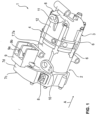
- the inside 1 Refrigerant compressor 1 shown is installed in a refrigerant circuit, not shown, of an air conditioning system of a motor vehicle.
- the electric motor refrigerant compressor 1 has an electric (electric motor) drive module 2 and a compressor module coupled to it in the form of a scroll compressor 3 .
- the scroll compressor 3 is connected in drive terms to the drive module 2 via a mechanical interface 4 formed between the drive module 2 and the scroll compressor 3 .
- the mechanical interface 4 serves as a bearing plate on the drive side and forms an intermediate wall 5 (FIGS. 2 and 3).
- the scroll compressor 3 is connected (joined, screwed) to the drive module 2 by means of flange connections 6 distributed on the circumference and extending in the axial direction A of the refrigerant compressor 1 .
- a partial housing area of a drive housing 7 of the refrigerant compressor 1 is designed as a motor housing 7a for accommodating an electric motor 13 ( 2 ) educated and on the one hand by an integrated housing partition 7b ( 2 ) to an electronics housing 7d provided with a housing cover 7c with motor electronics (electronics) 8 controlling the electric motor 13 and on the other hand closed by the mechanical interface 4 with the end shield and the intermediate wall 5 .
- the drive housing 7 has a connection section 9 with motor connections 9a and 9b routed to the electronics 8 for electrically contacting the electronics 8 to an on-board network of the motor vehicle.
- the drive housing 7 has a refrigerant inlet or refrigerant feed 10 for connection to the refrigerant circuit and a refrigerant outlet 11 .
- the outlet 11 is formed on the bottom of a compressor housing 12 of the scroll compressor 3 .
- the inlet 10 forms the low-pressure or suction side (suction gas side) and the outlet 11 forms the high-pressure or pump side (pump side) of the refrigerant compressor 1.
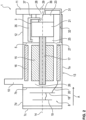
- FIG. 2 shows schematically the electric motor refrigerant compressor 1 in a sectional view along a rotation axis 14 of the electric motor 13, which is a brushless direct current motor (BLDC) and has a cylindrical rotor 15. This is surrounded on the circumference by a hollow-cylindrical stator 16 .
- the rotor 15 comprises a number of permanent magnets and is rotatably mounted about the axis of rotation 14 by means of a shaft 17 .
- the stator 16 has a number of electrical coils, which are energized by means of the electronics 8, which in turn is connected, for example, to a bus system and the on-board network of the motor vehicle.
- the electronics 8 are arranged in the electronics housing 7d of the drive housing 7, which is separated from the stator 16 and the rotor 15 by means of the intermediate wall 5.
- the housing cover 7c which is detachably attached to the electronics housing 7d by means of screws, closes an access opening in the electronics housing 7b.
- the motor electronics 8 has printed circuit boards 18, 19 which are arranged one above the other in the axial direction A.
- the bridge circuit is fed by the vehicle electrical system and controlled by a control circuit on the other printed circuit board 19, which is connected to the bus system in terms of signals.
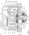
- the scroll compressor 3 has a movable scroll (scroll part) 21 arranged in the compressor housing 12 .
- This is coupled via an eccentric shaft journal 17a with, for example, two joining pins, of which only one joining journal 17b is visible, to the shaft 17 of the electric motor 13, which is guided into the mechanical interface 4 with the A-side end shield.
- the eccentric shaft journal 17a is mounted in a roller or ball bearing 22a held in the movable scroll 21.
- Another roller or ball bearing 22b supporting the shaft 17 is arranged in the mechanical interface 4 serving as the A-side end shield and in the intermediate wall 5 there.
- the movable scroll (scroll part) 21 is orbitally driven in operation of the scroll compressor 3 .
- the scroll compressor 3 also has a fixed scroll (scroll part) 23 rigidly fastened in the compressor housing 12 .
- the two scrolls (scroll parts) 21, 23 mesh with their snail or spiral scroll walls (scroll spirals) 21a, 23a, which protrude axially from a respective base plate 21b, 23b.
- Compressor chambers 24 are formed between their scroll walls or scroll spirals 21a, 23a and the base plates 21b, 23b, the volume of which is changed when the electric motor 13 is in operation.
- a counter-pressure chamber (back-pressure chamber) 25 in the intermediate wall 5.
- This is in the compressor housing 12, referred to simply as the housing below, from the base plate 21b of the movable scroll 21 and/or from an intermediate plate (wear plate) 5a ( 3 ) limited in the form of a steel plate, which has good sliding properties for the orbiting scroll 21.
- the back pressure chamber 25 partially extends into the base plate 21b of the movable scroll 21 .
- the coolant is introduced through the inlet 10 into the drive housing 7 and there into the motor housing 7a.
- This area of the drive housing 7 forms the suction or low-pressure side 26.
- the intermediate wall 7b of the housing prevents the coolant from penetrating into the electronics housing 7d.
- the refrigerant is mixed with oil present in the refrigerant circuit and passed along the rotor 15 and the stator 16 through an opening (or several openings, 3 ) 27 in the intermediate wall 5 to the scroll compressor 3.
- the mixture of refrigerant and oil is compressed by means of the scroll compressor 3, with the oil being used to lubricate the two scrolls 21, 23, so that friction is reduced and consequently efficiency is increased.
- the oil also serves as a seal in order to prevent the coolant located between the two scrolls (scroll parts) 21, 23 from escaping in an uncontrolled manner.
- the compressed refrigerant and oil mixture is directed into a high pressure chamber 29 within the compressor housing 12 via a central outlet 28 in the base plate 23b of the fixed scroll 23 .
- an oil separator (cyclone separator) 30 In the high-pressure chamber 29 there is an oil separator (cyclone separator) 30. Inside the oil separator 30, the mixture of refrigerant and oil is set in a rotary motion, with the heavier oil due to increased inertia and increased mass being directed to the walls of the oil separator 30 and in a lower portion of the oil separator 30 while the refrigerant is discharged upward or sideways through the outlet 11.
- the high pressure chamber 29 is defined within the housing 12 by the base plate 23b of the fixed scroll 23.
- the central outlet 28 into the high pressure or discharge chamber 29, which is located in the radially innermost chamber region 24' of the compression chambers 24, is drilled into the base plate 23b of the fixed scroll 23.
- the central outlet 28 is closed with a spring valve (finger spring valve) 33 as long as the pressure in the compression chambers 24 is lower than the pressure in the high-pressure chamber 29. If If the pressure of the compressed refrigerant-oil mixture in the compressor chambers 24, in particular in the central chamber region 24', is greater than the pressure in the high-pressure chamber 29, the spring valve 33 opens more or less automatically.
- a stop element 34 which is fixed in the high-pressure chamber 29 to the fixed scroll 23, for example to its base plate 23b, limits the stroke of the spring valve 33.
- the spring valve 33 closes the outlet 28 again automatically due to its spring preload. In this way, the compressed refrigerant-oil mixture - depending on the speed of the shaft 17 or depending on the operating point of the scroll compressor 3 - passes continuously (continuously) or intermittently or pulsating via the central outlet 28 from the compressor chamber 24 into the high-pressure chamber 29.
- a pressure line 35 is provided in the stationary scroll 23 , via which the compression chambers 24 and the high-pressure chamber 29 communicate with the counter-pressure chamber 25 in terms of flow.
- the pressure line 35 is connected via a first channel 36 to the compressor chambers 24 formed between the scroll walls 21a, 23a and via a second channel 37 to the high-pressure chamber 29 in an area which, during operation, essentially contains the refrigerant and only a small amount of oil having.
- FIG. 4 shows schematically in a block diagram the fluidic or pressure-carrying connection of the counter-pressure chamber 25 via the pressure line 35 and the two channels 36, 37, which act as orifices or throttles, on the one hand with the high-pressure chamber 29 and on the other hand with the compressor chambers 24.
- the in the base plate 23b of the fixed scroll 23, for example as a bore, is provided with the reference numeral 36, as is its diaphragm or throttle symbol.
- An oil return 38 including a throttle element 39, is shown as a broken (dashed) line, from the high-pressure chamber 29 in the region of the oil separator 30 into the low-pressure chamber (Suction gas chamber) 26. This is fluidically connected to the compressor chambers 24 of the scroll compressor 3 via the suction gas opening 27, as illustrated by the broken arrow line 40.
- the pressure line 35 is made up of a first line section 35a, which is introduced into the base plate 23b of the fixed scroll 23, suitably as a radially running bore, and a second line section 35b, which is suitably made as an axially running bore in a cup-shaped boundary wall 23c of the fixed scroll 23 is arranged.
- the second line section 35b can also be introduced into the (axial) housing wall of the compressor housing 12 .
- the bores or line sections 35a, 35b open into one another within the base plate 23b or merge into one another.
- the inlet opening of the radial bore of the first line section 35a is closed on the circumference of the boundary wall 23c in a manner not shown in detail.
- the counter-pressure chamber 25 is separated from the suction or low-pressure chamber 26 by means of the intermediate wall 5 .
- the intermediate wall 5 which accommodates the bearing 22a and 22b for the shaft journal 17a and the shaft 17 as an end shield, a third line section 35c of the pressure line 35 leading to the counter-pressure chamber 25 is arranged.
- This line section 35c can be designed analogously as a radially running bore in the intermediate wall 5 .
- the third line section 35c in the intermediate wall (interface) 5 can be designed as a groove which is open toward the orbiting scroll 21 and is closed by the intermediate plate (ware plate) 5a.
- the cross-sectional area of the pressure line 35 is many times, for example ten times smaller than the cross-sectional area of the central outlet 28. However, the cross-sectional area of the pressure line 35 is many times larger than the cross-sectional area of the two channels 36 and 37. In addition, the cross-sectional area of the with the compression chambers 24 connected to the first duct 36 is larger than the cross-sectional area of the second duct 37 connected to the high-pressure chamber 29.
- the diameter of the central outlet 28 is between 5mm and 10mm.
- the diameter of the pressure line 35 is between 1 mm and 10 mm.
- the diameter of the first channel 36 is 0.5 mm, for example, and the diameter of the second channel 37 is 0.25 mm, for example, each with a circular bore or channel cross section.
- the first channel 36 and the second channel 37 are designed as bores and (in terms of flow) act as an orifice plate or throttle. With this, from the pressure line 35 and the two channels 36, 37 formed channel system a particularly effective flow control of the (static) pressure in the back pressure chamber 25 is achieved.
- the radial distance between the first channel 36, which is connected to the compressor chambers 24, and the central outlet 28, which is arranged in the base plate 23b of the fixed scroll 23 and leads into the high-pressure chamber 29, is greater than the radial distance between the second channel 37, which is connected to the high-pressure chamber 29, and the central outlet Outlet 28.
- the second channel 37 can also be arranged closer to the central outlet 28 than the first channel 36. It is essential that the two channels 36 and 37 are not arranged directly axially opposite one another.
- the Figures 5 and 6 show in a perspective representation and in a plan view the fixed scroll 23 with the first channel 36 in the base plate 23b is arranged at a predetermined angular position P K1 within the scroll wall (scroll spiral) 23a and leads there to the pressure line 35, ie to its first line section 35a running inside the base plate 23b.
- the channel exit of the second line section 35b, which opens into the third line section 35c, within the boundary wall 23c of the fixed scroll 23, which is preferably closed all the way around, can also be seen.
- the Figures 7 and 8 show a perspective representation or a plan view of the fixed scroll 23 with a view of its plate side of the base plate 23b located in the high-pressure chamber 29.
- a filter (filter insert) 42 is received in this receiving opening 41, which has a filter shaft 42a and an orifice or throttle head 42b, in which the second channel 37, for example as a central bore , is provided.
- the opening 41 is surrounded in the manner of a collar by a wall 43 for receiving, positioning and/or stabilizing the position of the screen or throttle head 42b of the filter (filter insert) 42 .
- the first line section 35a of the pressure line 35 is formed by two sections a 1 , a 2 in the form of oblique bores which are made in the base plate 23b from the receiving opening 41 .
- the first section a 1 runs in the direction of the center or the central region of the base plate 23b.
- the second section a 2 runs to the second line section 35b of the pressure line 35 in the boundary wall 35c of the fixed scroll 23 and opens there into the second line section 35b of the pressure line 35.
- the first channel 36 opens out, producing the connection (in terms of pressure and/or flow) of the compression chambers 24 to the pressure line 35 and via this to the in figure 9 counter-pressure chamber 25, not shown.
- the two flow-regulating channels 36, 37 and their connection to the pressure line 35 leading into the counter-pressure chamber 25 in the fixed scroll 23 achieve a particularly effective, self-adjusting adjustment of the pressure in the counter-pressure chamber 25 in practically all working areas or points of the scroll compressor 3 .
- the adaptive control of the pressure in the counter-pressure chamber 25 by means of the two channels 36, 37 and the pressure line 35 in the fixed scroll 23 is just as reliable and self-adjusting at a suction pressure (low pressure) of 3 bar and a high pressure of 15 bar as with a Suction pressure of 3 bar and a high pressure of 25 bar or a suction pressure of 1.5 bar and a high pressure of 15 bar (working point in heat pump operation).
- the scroll compressor 3 and thus the refrigerant compressor 1 can therefore be operated with high efficiency at operating points in the cooling mode and in the heat pump mode of a vehicle air conditioning system.
- the flow control and adaptive adjustment of the pressure in the counter-pressure chamber 25, also at different operating points of the scroll compressor 3, can be influenced by the cross-sectional ratios of the pressure line 35 and the two channels 36, 37 and their positioning in relation to the compressor chamber(s) 24.
- the position P K1 , P K2 of the first channel 36 is selected such that it opens at a relative volume of the compressor chamber 24 of approximately 90% and remains open up to a relative chamber volume of approximately 25%.
- the scroll compressor 3 which is provided and set up in particular for refrigerants of a vehicle air conditioning system, has in a compressor housing 12 with a high-pressure chamber 27 and with compressor chambers 24 as well as with a counter-pressure chamber (back-pressure chamber) 25, a fixed scroll 23 and a movable scroll 23 that orbits (oscillates) during compressor operation , performing a rolling motion) Scroll 21 up.
- the scrolls 21, 23, which each have a base plate 21a, 23a and a scroll or spiral wall 21a integral with this (formed onto it), form the compressor chamber(s) 24 between their intermeshing scroll or spiral walls 21a or 23a
- the base plate 23b of the fixed scroll 23 defines the high pressure chamber 27, and the base plate 21b of the movable scroll 21 defines the back pressure chamber 25.
- the counter-pressure chamber 25 is connected to at least one of the compression chambers 24 via a pressure line 35 running at least partially in the fixed scroll 23 and a first channel 36 and to the high-pressure chamber 27 via a second channel 37 . Due to the operation, a static pressure is created or prevails in the pressure line 35, via which the counter-pressure chamber 25 communicates fluidically with the high-pressure chamber 27 and with the at least one of the compressor chambers 24, and also acts in the counter-pressure chamber 25.
Landscapes
- Engineering & Computer Science (AREA)
- Mechanical Engineering (AREA)
- General Engineering & Computer Science (AREA)
- Rotary Pumps (AREA)
- Applications Or Details Of Rotary Compressors (AREA)
Description
Die Erfindung liegt auf dem Gebiet der Verdrängermaschinen nach dem Spiralprinzip und betrifft einen, insbesondere elektromotorischen, Scrollverdichter als Kältemittelkompressor für eine Fahrzeugklimaanlage, gemäß dem Oberbegriff des Anspruchs 1. Eine derartige Verdrängermaschiene und insbesondere ein solcher Scrollverdichter ist aus der
Bei Kraftfahrzeugen sind regelmäßig Klimaanlagen eingebaut, die mit Hilfe einer einen Kältemittelkreislauf bildenden Anlage den Fahrzeuginnenraum klimatisieren. Derartige Anlagen weisen grundsätzlich einen Kreislauf auf, in dem ein Kältemittel geführt ist. Das Kältemittel, beispielsweise Kohlenstoffdioxid (CO2) oder R-134a (1,1,1,2-Tetrafluorethan) oder R-744 (Kohlenstoffdioxid), wird an einem Verdampfer erwärmt und mittels eines (Kältemittel-)Verdichters beziehungsweise Kompressors verdichtet, wobei das Kältemittel anschließend über einen Wärmetauscher die aufgenommene Wärme wieder abgibt, bevor es über eine Drossel erneut zum Verdampfer geführt wird.Air conditioning systems are regularly installed in motor vehicles, which air-condition the vehicle interior with the aid of a system forming a refrigerant circuit. Such systems basically have a circuit in which a refrigerant is guided. The refrigerant, for example carbon dioxide (CO 2 ) or R-134a (1,1,1,2-tetrafluoroethane) or R-744 (carbon dioxide), is heated in an evaporator and compressed by means of a (refrigerant) compressor or compressor, where the refrigerant then releases the heat it has absorbed via a heat exchanger before it is fed back to the evaporator via a throttle.
Als Kältemittelverdichter wird häufig die Scroll-Technologie eingesetzt, um ein Kältemittel-Öl-Gemisch zu verdichten. Das dabei entstehende Gas-Öl-Gemisch wird getrennt, wobei das abgetrennte Gas in den Klimakreislauf eingebracht wird, während das abgetrennte Öl gegebenenfalls innerhalb des Scrollverdichters als geeigneterweise elektromotorisch angetriebenen Kältemittelverdichter zur Schmierung von bewegten Teile an diese herangeführt werden kann.Scroll technology is often used as a refrigerant compressor to compress a refrigerant-oil mixture. The resulting gas-oil mixture is separated, with the separated gas being introduced into the air conditioning circuit, while the separated oil can be fed to the scroll compressor as a suitably electric motor-driven refrigerant compressor for lubricating moving parts.
Der Aufbau und die Funktionsweise eines solchen Scrollverdichters für das Kältemittels bzw. das Kältemittel-ÖI-Gemisch einer Kraftfahrzeugklimaanlage ist beispielsweise in der
Wesentliche Bestandteile des Scrollverdichters sind ein feststehender Scroll (fixed scroll) und ein beweglicher, orbitierender Scroll (movable, orbiting scroll). Die beiden Scrolls (Scrollteile) sind grundsätzlich gleichartig aufgebaut und weisen jeweils eine Basisplatte (base plate) und eine spiralförmige, ausgehend von der Basisplatte sich in Axialrichtung erstreckende Wandung (wrap) auf. Im zusammengesetzten Zustand liegen die Spiralwände der beiden Scrolls ineinander und bilden zwischen den sich abschnittsweise berührenden Scroll-Wandungen mehrere Verdichterkammern.Essential components of the scroll compressor are a fixed scroll (fixed scroll) and a movable, orbiting scroll (movable, orbiting scroll). The two scrolls (scroll parts) are basically constructed in the same way and each have a base plate and a spiral-shaped wall (wrap) extending in the axial direction starting from the base plate. In the assembled state, the spiral walls of the two scrolls lie within one another and form several compression chambers between the scroll walls that touch one another in sections.
Wenn der bewegliche Scroll orbitiert, gelangt das angesaugte Gas-Öl-Gemisch über einen Einlass zu einer ersten, radial äußeren Verdichterkammer und von dort über weitere Verdichterkammern zur radial innersten Verdichterkammer sowie von dort über einen zentralen Auslass, beispielsweise in Form einer Bohrung, und gegebenenfalls zwei benachbarte Nebenventile in Form ebenfalls von Bohrungen in der Basisplatte des feststehenden Scrolls in eine Auslass- oder Hochdruckkammer. Das Kammervolumen in den Verdichterkammern wird von radial außen nach radial innen kleiner, und der Druck des zunehmend verdichtenden Mediums wird größer. Während des Betriebs des Scrollverdichters steigt somit der Druck in den Verdichterkammern von radial außen nach radial innen an.When the movable scroll orbits, the sucked-in gas-oil mixture reaches a first, radially outer compression chamber via an inlet and from there via further compression chambers to the radially innermost compression chamber and from there via a central outlet, for example in the form of a bore, and possibly two adjacent auxiliary valves in the form of also bores in the base plate of the fixed scroll into a discharge or high-pressure chamber. The chamber volume in the compression chambers decreases from radially outside to radially inside, and the pressure of the increasingly compressing medium increases. During operation of the scroll compressor, the pressure in the compressor chambers thus increases from radially outside to radially inside.
Der zentrale Gas-Öl-Auslass (und gegebenenfalls jedes der Nebenventile bzw. - bohrungen) ist auf der Basisplattenrückseite des feststehenden Scrolls durch ein Federventil verschlossen. Das Federventil öffnet in Folge der Druckdifferenz zwischen den Verdichterkammern und der Hochdruckkammer. Gegebenenfalls strömt das verdichtete Gas-Öl-Gemisch nach Auslösen des Federventils in die Hochdruckkammer des Scrollverdichters (auf der Rückseite des feststehenden Scrolls), um dort in Öl und Gas getrennt zu werden. Anschließend, wenn der Druck in den der Hochdruckkammer gegenüberliegenden Verdichterkammern entsprechend abgesunken ist, schließt das Federventil automatisch.The central gas-oil outlet (and each of the auxiliary valves or bores, if applicable) is located on the baseplate rear of the fixed scroll through a Spring valve closed. The spring valve opens as a result of the pressure difference between the compression chambers and the high-pressure chamber. If necessary, after the spring valve has been triggered, the compressed gas-oil mixture flows into the high-pressure chamber of the scroll compressor (on the back of the fixed scroll) where it is separated into oil and gas. Then, when the pressure in the compression chambers opposite the high-pressure chamber has dropped accordingly, the spring valve closes automatically.
Während des Betriebs des Scrollverdichters werden aufgrund des in den Verdichterkammern erzeugten Drucks und der dadurch bedingten Axialkraft die beiden Scrolls auseinander gedrückt, so dass ein Spalt und somit Leckagen zwischen den Verdichterkammern entstehen können. Um dies möglichst zu vermeiden, wird - gegebenenfalls zusätzlich zu einem Ölfilm zwischen den Reibflächen der beiden Scrolls - der orbitierende Scroll gegen den feststehenden Scroll gedrückt. Die entsprechende Axialkraft (Gegenkraft) wird erzeugt, indem auf der Basisplattenrückseite des orbitierenden Scrolls ein Druckraum (Gegendruckkammer, back pressure chamber) vorgesehen ist, in der ein spezifischer Druck erzeugt wird.During the operation of the scroll compressor, the two scrolls are pressed apart due to the pressure generated in the compressor chambers and the resulting axial force, so that a gap and thus leaks can arise between the compressor chambers. In order to avoid this as far as possible, the orbiting scroll is pressed against the fixed scroll - if necessary in addition to an oil film between the friction surfaces of the two scrolls. The corresponding axial force (counterforce) is generated by providing a pressure chamber (back pressure chamber) on the back of the base plate of the orbiting scroll, in which a specific pressure is generated.
Dies kann gemäß der bereits genannten
In Abhängigkeit von der Positionierung des Mitteldruckkanals (back pressure port) steigt bei dem bekannten Scrollverdichter der Druck in der Gegendruckkammer bei einem Druckverhältnis von beispielsweise 3 bar (Niederdruck) zu 25 bar (Hochdruck) auf beispielsweise ca. 6 bar bis ca. 9 bar an. Bei dem bekannten Kältemittelscrollverdichter für eine Kraftfahrzeugklimaanlage ist der Mitteldruckkanal, ausgehend vom Anfang der Scrollspirale (Spiralwand) des beweglichen (orbitierenden) Scrolls bei etwa 405° positioniert.Depending on the positioning of the medium-pressure channel (back pressure port), the pressure in the back-pressure chamber in the known scroll compressor increases to, for example, approx. 6 bar to approx. 9 bar at a pressure ratio of, for example, 3 bar (low pressure) to 25 bar (high pressure). . In the known refrigerant scroll compressor for a motor vehicle air conditioning system, the medium-pressure channel is positioned at approximately 405°, starting from the start of the scroll spiral (spiral wall) of the movable (orbiting) scroll.
In "
In "
In beiden p-v-Diagrammen ist in dem betrachten Volumenbereich ein (relativer) Druckabfall bzw. Druckanstieg um den Faktor 2 (von 2.0 auf 1.0 bzw. von 1.0 auf 2.0) erkennbar. Der Öffnungs-Startwert des back pressure ports liegt somit bei ca. 100% bzw. bei ca. 95% des relativen Verdichterkammervolumens.In both p-v diagrams, a (relative) pressure drop or pressure increase by a factor of 2 (from 2.0 to 1.0 or from 1.0 to 2.0) can be seen in the volume range under consideration. The opening starting value of the back pressure port is therefore approximately 100% or approximately 95% of the relative compressor chamber volume.
In "
In "
Aus der
In der
Aus der
Der Erfindung liegt die Aufgabe zugrunde, einen besonders geeigneten, insbesondere elektromotorisch angetriebenen oder antreibbaren, Scrollverdichter als Kältemittelverdichter für eine Fahrzeugklimaanlage anzugeben. Insbesondere soll durch ein geeignetes Druckkanalsystem eine möglichst flexible und effektive Anpassung des Drucks in der Gegendruckkammer (Backpressure-Kammer) an Arbeitspunkte des Scrollverdichters für eine Fahrzeugklimaanlage, vorzugsweise im Kühlungs- und Wärmepumpenmodus, erzielt werden. Auch sollen Leckagen möglichst weitgehend reduziert und Reibungsverluste zwischen dem feststehenden Scroll und dem orbitierenden Scroll vermieden oder zumindest möglichst minimal gehalten werden.The invention is based on the object of specifying a particularly suitable scroll compressor, in particular one that is or can be driven by an electric motor, as a refrigerant compressor for a vehicle air conditioning system. In particular, a suitable pressure duct system should be used to adapt the pressure in the counter-pressure chamber (back-pressure chamber) to operating points of the scroll compressor for a vehicle air-conditioning system, preferably in the cooling and heat pump mode, as flexibly and effectively as possible. Leakages should also be reduced as much as possible and friction losses between the fixed scroll and the orbiting scroll should be avoided or at least kept as minimal as possible.
Diese Aufgabe wird erfindungsgemäß gelöst durch die Merkmale des Anspruchs 1. Vorteilhafte Ausgestaltungen und Weiterbildungen sind Gegenstand der Unteransprüche.This object is achieved according to the invention by the features of claim 1. Advantageous refinements and developments are the subject matter of the dependent claims.
Der Scrollverdichter weist in einem Gehäuse mit einer Hochdruckkammer und mit Verdichterkammern sowie mit einer Gegendruckkammer einen feststehenden Scroll und einen beweglich, d. h. im angetriebenen Zustand - also im Betreib (Verdichterbetrieb) - orbitierenden (oszillierenden) Scroll auf. Die Scrolls oder Scrollteile weisen jeweils eine Basisplatte und eine Spiralwand auf, wobei zwischen den ineinandergreifenden Spiralwänden der beiden Scrolls (Scrollteile) die Verdichterkammern gebildet sind. Die Basisplatte des feststehenden Scrolls begrenzt die Hochdruckkammer, und die Basisplatte des beweglichen Scrolls begrenzt die Gegendruckkammer.In a housing with a high-pressure chamber and with compression chambers and with a back-pressure chamber, the scroll compressor has a fixed scroll and a movable, ie in the driven state—ie in operation (compressor operation)—orbiting (oscillating) scroll. The scrolls or scroll parts each have a base plate and a spiral wall, with between the interlocking spiral walls of the two scrolls (scroll parts) form the compression chambers. The base plate of the fixed scroll defines the high pressure chamber and the base plate of the movable scroll defines the back pressure chamber.
Die Gegendruckkammer steht über eine zumindest teilweise im feststehenden Scroll verlaufende Druckleitung mit zumindest einer der Verdichterkammern in Verbindung. Die Druckleitung steht über einen ersten Kanal mit zumindest einer der Verdichterkammern und zudem über einen zweiten Kanal mit der Hochdrucckammer in Verbindung. Auf diese Weise entsteht in der Druckleitung, über welche die Gegendruckkammer strömungstechnisch mit der Hochdruckkammer und mit der zumindest einen Verdichterkammer kommuniziert, ein auch in der Gegendruckkammer wirkender statischer Druck. Der Scrollverdichter ist insbesondere für Kältemittel einer Fahrzeugklimaanlage vorgesehene und eingerichtete.The counter-pressure chamber is connected to at least one of the compression chambers via a pressure line that runs at least partially in the stationary scroll. The pressure line is connected via a first channel to at least one of the compression chambers and also via a second channel to the high-pressure chamber. In this way, a static pressure that also acts in the back-pressure chamber is created in the pressure line, via which the back-pressure chamber communicates in terms of flow with the high-pressure chamber and with the at least one compression chamber. The scroll compressor is intended and set up in particular for refrigerants in a vehicle air conditioning system.
Geeigneterweise ist zumindest einer der Kanäle in der Basisplatte des feststehenden Scrolls angeordnet. Vorzugsweise sind der mit der Verdichterkammer verbundene erste Kanal und der mit der Hochdruckkammer verbundene zweite Kanal in der Basisplatte des feststehenden Scrolls angeordnet. In einer vorteilhaften Ausgestaltung ist der zweite Kanal in einem Filter (Filter-Einsatz) angeordnet, der in der Hochdruckkammer in eine Bohrungsöffnung eingesetzt ist, die in die Basisplatte auf deren Hochdruckkammer-Plattenseite eingebracht und dort von einem Positionier- und Haltekragen für den Filter-Einsatz umgeben ist.Suitably at least one of the channels is located in the base plate of the fixed scroll. Preferably, the first passage connected to the compression chamber and the second passage connected to the high-pressure chamber are located in the base plate of the fixed scroll. In an advantageous embodiment, the second channel is arranged in a filter (filter insert), which is inserted in the high-pressure chamber in a borehole that is introduced into the base plate on the high-pressure chamber plate side and is supported there by a positioning and holding collar for the filter insert is surrounded.
Die Druckleitung weist zweckmäßigerweise mindestens einen ersten Leitungsabschnitt, der in der Basisplatte des feststehenden Scrolls angeordnet ist, und einen mit dem ersten Leitungsabschnitt verbundenen zweiten Leitungsabschnitt auf, der in einer Begrenzungswand des feststehenden Scrolls angeordnet ist. Die Begrenzungswand kann Bestandteil des feststehenden Scrolls oder des Gehäuses sein.The pressure line expediently has at least a first line section, which is arranged in the base plate of the fixed scroll, and a second line section which is connected to the first line section and is arranged in a boundary wall of the fixed scroll. The boundary wall can be part of the fixed scroll or the housing.
Gemäß einer ersten Alternative ist in einfacher Weise der erste Leitungsabschnitt radial in die Basisplatte und der zweiten Leitungsabschnitt axial oder schräg verlaufend in die Begrenzungswand des feststehenden Scrolls in Form jeweils einer Bohrung eingebracht werden, wobei die Bohrungen innerhalb der Basisplatte unter Bildung der Druckleitung ineinander münden bzw. ineinander übergehen.According to a first alternative, in a simple manner, the first line section extends radially into the base plate and the second line section extends axially or obliquely into the boundary wall of the fixed scroll, each in the form of one Bore are introduced, the holes within the base plate to form the pressure line open into each other or merge into one another.
Gemäß einer zweiten Alternative, bei der der zweite Kanal in einem Filter (Filter-Einsatz) angeordnet bzw. von diesem gebildet ist, sind ausgehend von der Bohrungsöffnung in der Basisplatte des feststehenden Scrolls zwei schräg verlaufende, erste Leitungsabschnitte vorgesehen. Eine dieser ersten Leitungsabschnitte verläuft zum zweiten Leitungsabschnitt in der Begrenzungswand und mündet in diese ein. Der andere dieser ersten Leitungsabschnitte verläuft zum ersten Kanal, d. h. innerhalb der Basisplatte des feststehenden Scrolls in Richtung der (gewählten) Position des ersten Kanals.According to a second alternative, in which the second channel is arranged in a filter (filter insert) or formed by this, two obliquely running first line sections are provided starting from the bore opening in the base plate of the fixed scroll. One of these first line sections runs to the second line section in the boundary wall and opens into it. The other of these first line sections runs to the first channel, i. H. within the base plate of the fixed scroll towards the (selected) position of the first channel.
Die Gegendruckkammer ist mittels einer Zwischenwand von einer Niederdrucckammer abgegrenzt. In diese Zwischenwand, die geeigneterweise als Lagerschild für eine den beweglichen Scroll antreibende Welle dient, ist ein zur Gegendrucckammer führender (dritter) Leitungsabschnitt der Druckleitung angeordnet. Dieser Leitungsabschnitt kann wiederum in einfacher Weise als radiale Bohrung in der Zwischenwand ausgeführt sein. Alternativ ist dieser Leitungsabschnitt der Druckleitung als Nut in der Zwischenwand in Verbindung mit einer diese überdeckenden Platte (Wear-Plate) ausgeführt.The counter-pressure chamber is separated from a low-pressure chamber by means of an intermediate wall. A (third) line section of the pressure line leading to the back pressure chamber is arranged in this intermediate wall, which suitably serves as an end shield for a shaft driving the movable scroll. This line section can in turn be designed in a simple manner as a radial bore in the intermediate wall. Alternatively, this line section of the pressure line is designed as a groove in the intermediate wall in connection with a plate (wear plate) covering it.
Die Querschnittsfläche der Druckleitung ist erfindungsgemäß um mindestens den Faktor zwei (2) größer als die Querschnittsfläche des mit der Verdichterkammer verbundenen ersten Kanals und des mit der Hochdruckkammer verbundenen zweiten Kanals. Zusätzlich oder alternativ ist erfindungsgemäß vorgesehen, dass die Querschnittsfläche des mit der Verdichterkammer verbundenen ersten Kanals wiederum größer ist als die Querschnittsfläche des mit der Hochdruckkammer verbundenen zweiten Kanals.According to the invention, the cross-sectional area of the pressure line is at least a factor of two (2) larger than the cross-sectional area of the first channel connected to the compression chamber and the second channel connected to the high-pressure chamber. Additionally or alternatively, the invention provides that the cross-sectional area of the first channel connected to the compression chamber is in turn larger than the cross-sectional area of the second channel connected to the high-pressure chamber.
Geeigneterweise ist das Verhältnis zwischen der Querschnittsfläche des mit der Verdichterkammer verbundenen ersten Kanals und der Querschnittsfläche des mit der Hochdruckkammer verbundenen zweiten Kanals zwischen 3 (drei) und 5 (fünf), vorzugsweise 4 (vier). Zweckmäßigerweise sollten die Querschnittsflächen der beiden Kanäle möglichst klein sein.Suitably the ratio between the cross-sectional area of the first passage connected to the compression chamber and the cross-sectional area of the second passage connected to the high-pressure chamber is between 3 (three) and 5 (five), preferably 4 (four). The cross-sectional areas of the two channels should expediently be as small as possible.
Die Querschnittsfläche des mit der Verdichterkammer verbundenen ersten Kanals beträgt zweckmäßigerweise zwischen 0,03 mm2 und 1,5 mm2, vorzugsweise 0,2 mm2. Die Querschnittsfläche des mit der Hochdruckkammer verbundenen zweiten Kanals beträgt zweckmäßigerweise zwischen 0,008 mm2 und 0,2 mm2, vorzugsweise 0,05 mm2. Bezogen auf einen kreisrunden Kanalquerschnitt sollte der Durchmesser des ersten Kanals zwischen 0,2 mm und 1 mm, vorzugsweise 0,5 mm, und derjenige des zweiten Kanals zwischen 0,1 mm und 0,5 mm, vorzugsweise 0,25 mm, betragen.The cross-sectional area of the first duct connected to the compression chamber is expediently between 0.03 mm 2 and 1.5 mm 2 , preferably 0.2 mm 2 . The cross-sectional area of the second channel connected to the high-pressure chamber is expediently between 0.008 mm 2 and 0.2 mm 2 , preferably 0.05 mm 2 . Based on a circular channel cross-section, the diameter of the first channel should be between 0.2 mm and 1 mm, preferably 0.5 mm, and that of the second channel should be between 0.1 mm and 0.5 mm, preferably 0.25 mm.
In vorteilhafter Ausgestaltung sind der erste und/oder der zweite Kanal als Bohrung ausgeführt, welche in die Druckleitung mündet. Aufgrund der geringen Wanddicke (Wandstärke) der Basisplatte des feststehenden Scrolls im Bereich der beiden Kanäle wirkt die jeweilige Bohrung bzw. der jeweilige Kanal somit als Blende oder Drossel.In an advantageous embodiment, the first and/or the second channel are designed as a bore which opens into the pressure line. Due to the small wall thickness (wall thickness) of the base plate of the fixed scroll in the area of the two channels, the respective bore or the respective channel thus acts as an orifice or throttle.
Diese strömungstechnische Regelung und eine effektive adaptive Anpassung des Drucks in der Gegendruckkammer an unterschiedliche Arbeitspunkte des Scrollverdichters (im Kühlungs- oder Wärmepumpen-Modus) wird dadurch unterstützt oder kann dadurch weiter verbessert werden, dass der mit der Verdichterkammer verbundene erste Kanal - ausgehend von einem relativen Kammervolumen von etwa 100% in der radial äußersten Verdichterkammer und einem Rotations- oder Wellenwinkel von 0° - bei einem Rotations- oder Wellenwinkel von (63,5 ± 5,5)° vollständig geöffnet ist und bis zu einem Rotations- oder Wellenwinkel von (343,5 ± 5,5)° geöffnet bleibt. Dies entspricht einer relativen Volumenänderung des Verdicherkammervolumens von (91,15 ± 0,75)° auf (23,0 ± 0,3)°.This flow control and an effective adaptive adjustment of the pressure in the counter-pressure chamber to different operating points of the scroll compressor (in cooling or heat pump mode) is supported or can be further improved by the fact that the first channel connected to the compressor chamber - based on a relative chamber volume of about 100% in the radially outermost compressor chamber and a rotation or shaft angle of 0° - is fully open at a rotation or shaft angle of (63.5 ± 5.5)° and up to a rotation or shaft angle of ( 343.5 ± 5.5)° remains open. This corresponds to a relative volume change in the compressor chamber volume from (91.15 ± 0.75)° to (23.0 ± 0.3)°.
Die radialen Abstände der beiden Kanäle zu einem in der feststehenden Basisplatte angeordneten und in die Hochdruckkammer führenden zentralen Auslass sind geeigneterweise unterschiedlich groß, so dass die bedien Känale bewusst nicht einander direkt (axial) gegenüberliegend angeordnet sind. Dabei kann der radiale Abstand des in die Hochdruckkammer führenden zweiten Kanals größer oder kleiner sein als der radiale Abstand des mit der Verdichterkammer verbundenen ersten Kanals zum zentralen Auslass.The radial distances between the two channels and a central outlet which is arranged in the fixed base plate and leads into the high-pressure chamber are suitably of different sizes, so that the operating channels are deliberately not arranged directly (axially) opposite one another. The radial Distance of the second channel leading into the high-pressure chamber may be greater or smaller than the radial distance of the first channel connected to the compression chamber to the central outlet.
Die mit der Erfindung erzielten Vorteile bestehen insbesondere darin, dass durch die beiden strömungsregelnden Kanäle in deren Verbindung mit der Druckleitung in dem feststehenden Scroll eine effektive und selbst einstellende Anpassung des Drucks in der Gegendruckkammer an den jeweiligen Arbeitspunkt des Scrollverdichters ohne zusätzliche strömungsregelnde Bauteile zur Strömungsdrosselung, wie beispielsweise Ventile, Düsen, Drosseln oder weitere Känale, Bohrungen oder Blenden erfolgt.The advantages achieved with the invention are, in particular, that the two flow-regulating channels in their connection with the pressure line in the fixed scroll allow an effective and self-adjusting adjustment of the pressure in the counter-pressure chamber to the respective operating point of the scroll compressor without additional flow-regulating components for flow throttling, such as valves, nozzles, throttles or other channels, bores or orifices.
Die adaptive Regelung des Drucks in der Gegendruckkammer erfolgt mittels der beiden Kanäle und der Druckleitung im feststehenden Scroll bei einem Druckverhältnis zwischen Saugdruck (Niederdruck) und Hochdruck von 5 (bei einem Saugdruck von 3 bar und einem Hochdruck von 15 bar) ebenso zuverlässig selbst einstellend, wie bei einem Druckverhältnis von etwa 8 (bei einem Saugdruck von 3 bar und einem Hochdruck von 25 bar) oder 10 (bei einem Saugdruck von 1,5 bar und einem Hochdruck von 15 bar) für das Kältemittel R-134A (Arbeitspunkt beim Betrieb als Wärmepumpe).The adaptive control of the pressure in the counter-pressure chamber takes place by means of the two channels and the pressure line in the fixed scroll at a pressure ratio between suction pressure (low pressure) and high pressure of 5 (at a suction pressure of 3 bar and a high pressure of 15 bar) and is self-adjusting, just as reliably. as at a pressure ratio of about 8 (at a suction pressure of 3 bar and a high pressure of 25 bar) or 10 (at a suction pressure of 1.5 bar and a high pressure of 15 bar) for the refrigerant R-134A (working point when operating as heat pump).
Zudem kann mittels dieses Zwei-Kanal-Druckleitungs-Systems im feststehenden Scroll eine hohe Prozessstabilität für Serienfertigungen erreicht werden. So unterliegen die beiden Kanäle in dem feststehenden Scroll im Zuge einer Scroll-Beschichtung, beispielsweise einer Farbbeschichtung, quasi gleichen Bedingungen, so dass sich Toleranzen, die zu Schwankungen im Gegendruck- bzw. Backpressure-Niveau führen können, gegenseitig aufheben (herauskürzen).In addition, this two-channel pressure line system in the fixed scroll can be used to achieve high process stability for series production. The two channels in the stationary scroll are subject to virtually the same conditions during the course of a scroll coating, for example a paint coating, so that tolerances that can lead to fluctuations in the back pressure level cancel each other out (reduce).
Des Weiteren kann der Scrollverdichter aufgrund der adaptiven Anpassung des Drucks in der Gegendruckkammer bei Arbeitspunkten im Kühlungs- und im Wärmepumpenmodus mit hoher Effizienz betrieben werden, weil insbesondere Leckagen reduziert und Reibungsverluste zwischen den Scrollteilen auf ein Minimum gehalten werden können. So ist die in Folge des selbst einstellenden Drucks in der Gegendruckkammer wirksame Axialkraft aufgrund der adaptiven Anpassung nicht oder stets lediglich um einen geringen Betrag größer als die Summe der Axialkräfte in den Verdichterkammern, in denen im Verdichterbetrieb typischerweise unterschiedliche Drücke herrschen.Furthermore, due to the adaptive adjustment of the pressure in the back pressure chamber, the scroll compressor can be operated with high efficiency at operating points in cooling and heat pump mode, in particular because leakage can be reduced and friction losses between the scroll parts can be kept to a minimum. So is the result of the self-adjusting pressure in the Back pressure chamber effective axial force due to the adaptive adjustment not or always only a small amount greater than the sum of the axial forces in the compressor chambers, in which there are typically different pressures during compressor operation.
Die besonders effektive strömungstechnische Regelung und adaptive Anpassung des Drucks in der Gegendruckkammer an unterschiedliche Arbeitspunkte des Scrollverdichters wird vorteilhaft bestimmt bzw. beeinflusst durch die angegebenen Querschnittsverhältnisse der Druckleitung und der beiden Kanäle sowie deren Positionierung in Bezug auf die Verdichterkammer(n). So ist die Positionierung geeigneterweise derart gewählt, dass insbesondere der erste Kanal bei einem relativen Volumen der Verdichterkammer (Verdichterkammervolumen) von ca. 90% öffnet und im Zuge einer relativen Druckänderung bis zu einem relativen Volumen der Verdichterkammer von ca. 23% geöffnet bleibt, bevor der jeweilige Kanal während der orbitierenden Bewegung des orbitierenden Scrolls von dessen Spiralwand abgedeckt bzw. übergriffen wird und mit einer radial weiter außen liegenden Verdichterkammer in Verbindung (Überdeckung) steht.The particularly effective flow control and adaptive adjustment of the pressure in the counter-pressure chamber to different operating points of the scroll compressor is advantageously determined or influenced by the specified cross-sectional ratios of the pressure line and the two channels and their positioning in relation to the compressor chamber(s). The positioning is suitably selected in such a way that in particular the first channel opens at a relative volume of the compression chamber (compression chamber volume) of approx. 90% and remains open in the course of a relative pressure change up to a relative volume of the compression chamber of approx. 23% before the respective channel is covered or overlapped by its spiral wall during the orbiting movement of the orbiting scroll and is connected (overlapping) to a compressor chamber lying radially further outside.
Wenn der orbitierende Scroll vom Kompressionsvorgang des Kältemittel-Gas-Gemisches in den Verdichterkammern bis zum Ausstoßprozess des verdichteten Kältemittel-Gas-Gemisches in die Hochdruckkammer des Scrollverdichters typischerweise 2,5 Umdrehungen - und somit zwischen 0% und 100% relativem Verdichterkammervolumen - einen Winkelbereich von 900° durchläuft, sollte der die Verdichterkammer mit der Druckleitung verbindende erste Kanal im feststehenden Scroll bei einem Winkel (Spiralwinkel ϕ) von 350° bis 390°, insbesondere 370°, positioniert sein, wobei dieser Winkel ϕ ausgehend sowohl vom Anfang als auch vom Ende der Spiralwand (Scrollspirale) des feststehenden Scrolls gemessen (angelegt) sein kann.If the orbiting scroll from the compression process of the refrigerant-gas mixture in the compressor chambers to the discharge process of the compressed refrigerant-gas mixture into the high-pressure chamber of the scroll compressor typically 2.5 revolutions - and thus between 0% and 100% relative compressor chamber volume - an angular range of 900°, the first channel connecting the compression chamber with the penstock should be positioned in the fixed scroll at an angle (spiral angle ϕ) of 350° to 390°, especially 370°, this angle ϕ starting from both the beginning and the end the spiral wall (scroll spiral) of the fixed scroll can be measured (applied).
Die Position des zweiten Kanals, der die Druckleitung mit der Hochdruckkammer innerhalb des Gehäuses des Scrollverdichters verbindet, ergibt sich praktisch zwangsläufig entlang derselben Radius- oder Winkellinie, wenn die Druckleitung bzw. deren erster Leitungsabschnitt geradlinig ist. Bei der Variante mit schräg verlaufenden ersten Leitungsabschnitten können die beiden axial beabstandeten Kanäle an zueinander unterschiedlichen Radial- und/oder Azimutalposionen angerordnet sein.The position of the second duct, which connects the pressure line with the high-pressure chamber inside the scroll compressor housing, is practically inevitably along the same radius or angle line if the pressure line or its first line section is straight. In the variant with sloping first line sections, the two axially spaced channels can be arranged at mutually different radial and/or azimuthal positions.
Nachfolgend wird ein Ausführungsbeispiel der Erfindung anhand einer Zeichnung näher erläutert. Darin zeigen:
- Fig. 1
- in einer perspektivischen Seitenansicht einen Scrollverdichter mit einem elektromotorischen Antriebsmodul und mit einem Verdichtermodul,
- Fig. 2
- in einer Schnittdarstellung schematisch vereinfacht den elektromotorisch angetrieben Scrollverdichter mit einer Hochdruckkammer und mit einer Gegendruckkamer (Back-Pressure-Kammer) sowie mit in diese führendem Druckleitungs- bzw. Kanalsystem,
- Fig. 3
- in einer Schnittdarstellung den Scrollverdichter mit in einem Verdichtergehäuse einem feststehenden und einem beweglichen Scroll sowie mit einer zur Gegendruckkammer führenden Druckleitung mit jeweils einem Verbindungskanal (erster Kanal und zweiter Kanal) in die zwischen den Scrolls gebildeten Verdichterkammern einerseits und in die Hochdrucckammer andererseits,
- Fig. 4
- in einem Blockschaltbild die Druckrückführung aus der Hochdruckkammer und aus den scrollseitigen Verdichterkammern in die Gegendrucckammer sowie mit einer Ölrückführung in eine saug- bzw. motorseitige Niederdruckkammer,
- Fig. 5
- in einer perspektivischen Darstellung den feststehenden Scroll mit einem an einer innerhalb der Scrollwand (Scrollspirale) vorbestimmten Position (Winkel-Position) in der Basisplatte angeordneten Kanal (Bohrung) zur Druckleitung,
- Fig. 6
- in einer Draufsicht den feststehenden Scroll mit zwei eingezeichneten Winkelpositionen (Spiralwinkel) des zu einer Verdichterkammer führenden ersten Verbindungskanals in der Basisplatte,
- Fig. 7
- in einer perspektivischen Darstellung den feststehenden Scroll mit Blick auf die hochdruckkammerseitige Plattenfläche (Plattenseite) dessen Basisplatte und darin angeordneter Aufnahmeöffnung für einen Filtereinsatz mit dem (zweiten) Verbindungskanal zur Hochdruckkammer,
- Fig. 8
- den feststehenden Scroll gemäß
Fig. 7 in einer Draufsicht, und - Fig. 9
- einen Schnitt IX-IX aus
Fig. 8 mit von der Aufnahmeöffnung für den Filtereinsatz ausgehenden Leitungsabschnitten der Druckleitung zum ersten Verbindungskanal und zu einem Leitungsabschnitt in einer (radial äußeren) Begrenzungswand des feststehenden Scrolls.
- 1
- in a perspective side view a scroll compressor with an electric motor drive module and with a compressor module,
- 2
- in a sectional view, schematically simplified, the scroll compressor driven by an electric motor with a high-pressure chamber and a counter-pressure chamber (back-pressure chamber) and with the pressure line or channel system leading into it,
- 3
- in a sectional view, the scroll compressor with a fixed and a movable scroll in a compressor housing and with a pressure line leading to the counter-pressure chamber, each with a connecting channel (first channel and second channel) into the compression chambers formed between the scrolls on the one hand and into the high-pressure chamber on the other hand,
- 4
- in a block diagram, the pressure return from the high-pressure chamber and from the compressor chambers on the scroll side into the counter-pressure chamber and with an oil return into a low-pressure chamber on the intake or engine side,
- figure 5
- in a perspective view, the fixed scroll with a channel (bore) to the pressure line arranged at a predetermined position (angular position) within the scroll wall (scroll spiral) in the base plate,
- 6
- in a top view, the fixed scroll with two marked angular positions (spiral angle) of the first connecting channel in the base plate leading to a compressor chamber,
- 7
- in a perspective view of the fixed scroll with a view of the plate surface (plate side) on the high-pressure chamber side, its base plate and the receiving opening arranged therein for a filter insert with the (second) connecting channel to the high-pressure chamber,
- 8
- according to the fixed scroll
7 in a plan view, and - 9
- make a section IX-
IX 8 with line sections of the pressure line emanating from the receiving opening for the filter insert to the first connecting channel and to a line section in a (radially outer) boundary wall of the stationary scroll.
Einander entsprechende Teile und Größen sind in allen Figuren stets mit den gleichen Bezugszeichen versehen.Corresponding parts and sizes are always provided with the same reference symbols in all figures.
Der in
Ein Gehäuseteilbereich eines Antriebsgehäuses 7 des Kältemittelverdichters 1 ist als ein Motorgehäuse 7a zur Aufnahme eines Elektromotors 13 (
Das Antriebsgehäuse 7 weist einen Kältemittel-Einlass oder Kältemittel-Zulauf 10 zum Anschluss an den Kältemittelkreislauf und einen Kältemittel-Auslass 11 auf. Der Auslass 11 ist an dem Boden eines Verdichtergehäuses 12 des Scrollverdichter 3 angeformt. Im angeschlossenen Zustand bildet der Einlass 10 die Niederdruck- oder Saugseite (Sauggasseite) und der Auslass 11 die Hochdruck- oder Pumpseite (Pumpenseite) des Kältemittelverdichters 1.The drive housing 7 has a refrigerant inlet or
Die Elektronik 8 ist im Elektronikgehäuse 7d des Antriebsgehäuses 7 angeordnet, das von dem Stator 16 und dem Rotor 15 mittels der Zwischenwand 5 getrennt ist. Der Gehäusedeckel 7c, der mittels Schrauben am Elektronikgehäuse 7d lösbar befestigt ist, verschließt eine Zugangsöffnung des Elektronikgehäuses 7b. Die Motorelektronik 8 weist Leiterplatten 18, 19 auf, die in Axialrichtung A übereinander angeordnet sind. Eine Brückenschaltung der Leiterplatte 18, welche der Gehäusezwischenwand 7b nächstgelegen ist, ist über Bestromungsleitungen 19, welche durch die Gehäusezwischenwand 7b geführt sind, mit den elektrischen Spulen des Stators 16 kontaktiert. Die Brückenschaltung wird mittels des Bordnetzes gespeist und mittels einer Ansteuerschaltung der anderen Leiterplatte 19 gesteuert, die signaltechnisch mit dem Bus-System verbunden ist.The
Wie in Verbindung mit
Der Scrollverdichter 3 weist zudem einen starr im Verdichtergehäuse 12 befestigten feststehenden Scroll (Scrollteil) 23 auf. Die beiden Scrolls (Scrollteile) 21, 23 greifen mit deren schnecken- oder spiralförmigen Scrollwänden (Scrollspiralen) 21a, 23a ineinander, die von einer jeweiligen Basisplatte 21b, 23b axial emporragen. Zwischen den Scrolls 21, 23, d. h. zwischen deren Scrollwänden bzw. Scrollspiralen 21a, 23a und den Basisplatten 21b, 23b sind Verdichterkammern 24 gebildet, deren Volumen bei Betrieb des Elektromotors 13 verändert wird.The
Zwischen dem A-seitigen Lagerschild und dem beweglicher Scroll 21 befindet sich in der Zwischenwand 5 eine Gegendruckkammer (Backpressure-Kammer) 25. Diese ist im - nachfolgend einfach als Gehäuse bezeichneten - Verdichtergehäuse 12 von der Basisplatte 21b des beweglichen Scrolls 21 und/oder von einer Zwischenplatte (Wear-Plate) 5a (
Beim Betrieb wird das Kältemittel durch den Zulauf 10 in das Antriebsgehäuse 7 und dort in das Motorgehäuse 7a eingeleitet. Dieser Bereich des Antriebsgehäuses 7 bildet die Saug- oder Niederdruckseite 26. Mittels der Gehäusezwischenwand 7b wird ein Eindringen des Kältemittels in das Elektronikgehäuse 7d verhindert. Innerhalb des Antriebsgehäuses 7 wird das Kältemittel mit in dem Kältemittelkreislauf vorhandenem Öl vermischt und entlang des Rotors 15 und des Stators 16 durch eine Öffnung (oder mehrere Öffnungen,
Das verdichtete Gemisch aus Kältemittel und Öl wird über einen zentralen Auslass 28 in der Basisplatte 23b des feststehenden Scrolls 23 in eine Hochdruckkammer 29 innerhalb des Verdichtergehäuses 12 geleitet. In der Hochdruckkammer 29 befindet sich ein Ölabscheider (Zyklonabscheider) 30. Innerhalb des Ölabscheiders 30 wird das Gemisch aus Kältemittel und Öl in eine Rotationsbewegung versetzt, wobei das schwerere Öl aufgrund der erhöhten Trägheit und erhöhten Masse zu den Wänden des Ölabscheiders 30 geleitet und in einem unteren Bereich des Ölabscheiders 30 gesammelt wird, während das Kältemittel nach oben oder seitlich durch den Auslass 11 abgeführt wird.The compressed refrigerant and oil mixture is directed into a
Wie in
Ein Anschlagelement 34, das in der Hochdruckkammer 29 am feststehenden Scroll 23, beispielsweise an dessen Basisplatte 23b, befestigt ist, begrenzt den Hub des Federventils 33. Wenn der Druck auf unterhalb des Drucks in der Hochdruckkammer 29 abgesunken ist, verschließt das Federventil 33 den Auslass 28 erneut selbsttätig aufgrund dessen Federvorspannung. Auf diese Weise gelangt das verdichtete Kältemittel-Öl-Gemisches -je nach Drehzahl der Welle 17 bzw. in Abhängigkeit vom Arbeitspunkt des Scrollverdichters 3 - kontinuierliche (durchgängig) oder stoßweise oder pulsierend über den zentralen Auslass 28 aus den Verdichterkammer 24 in die Hochdruckkammer 29.A
Im feststehenden Scroll 23 ist eine Druckleitung 35 vorgesehen, über welche die Verdichterkammern 24 und die Hochdruckkammer 29 strömungstechnisch mit der Gegendruckkammer 25 kommunizieren. Hierzu steht die Druckleitung 35 über einen ersten Kanal 36 mit den zwischen den Scrollwänden 21a, 23a gebildeten Verdichterkammern 24 und über einen zweiten Kanal 37 mit der Hochdruckkammer 29 in einem Bereich in Verbindung, der bei Betrieb im Wesentlichen das Kältemittel und nur eine geringe Menge Öl aufweist.A
Ebenfalls in
Bei der Ausführungsform gemäß
Die Gegendruckkammer 25 ist mittels der Zwischenwand 5 von der Saug- oder Niederdruckkammer 26 abgegrenzt. In die Zwischenwand 5, welche als Lagerschild die Lager 22a und 22b für den Wellenzapfen 17a und die Welle 17 aufnimmt, ist ein zur Gegendruckkammer 25 führender dritter Leitungsabschnitt 35c der Druckleitung 35 angeordnet. Dieser Leitungsabschnitt 35c kann analog als radial verlaufende Bohrung in der Zwischenwand 5 ausgeführt sein. Alternativ kann der dritte Leitungsabschnitt 35c in die Zwischenwand (Schnittstelle) 5 als zum orbitierenden Scroll 21 hin offene und durch die Zwischenplatte (Ware-Plate) 5a verschlossene Nut ausgeführt sein.The
Die Querschnittsfläche der Druckleitung 35 ist um ein Vielfaches, beispielsweise um das zehnfache, kleiner als die Querschnittsfläche des zentralen Auslasses 28. Die Querschnittsfläche der Druckleitung 35 ist jedoch um ein Vielfaches größer als die Querschnittsfläche der beiden Kanäle 36 und 37. Zudem ist die Querschnittsfläche des mit den Verdichterkammern 24 verbundenen ersten Kanals 36 größer als die Querschnittsfläche des mit der Hochdruckkammer 29 verbundenen zweiten Kanals 37.The cross-sectional area of the
Der Durchmesser des zentralen Auslasses 28 beträgt zwischen 5 mm und 10 mm. Der Durchmesser der Druckleitung 35 beträgt zwischen 1 mm und 10 mm. Der Durchmesser des ersten Kanals 36 beträgt beispielsweise 0,5 mm, und der Durchmesser des zweiten Kanals 37 beträgt beispielsweise 0,25 mm, jeweils bei kreisförmigem Bohrungs- oder Kanalquerschnitt.The diameter of the
Der erste Kanal 36 und der zweite Kanal 37 sind als Bohrungen ausgeführt und (strömungstechnisch) als Blende bzw. Drossel wirksam. Mit diesem, aus der Druckleitung 35 und den beiden Kanälen 36, 37 gebildeten Kanalsystem wird eine strömungstechnisch besonders effektive Regelung des (statischen) Drucks in der Gegendruckkammer 25 erreicht. Der radiale Abstand des mit den Verdichterkammern 24 verbundenen ersten Kanals 36 zum in der Basisplatte 23b des feststehenden Scrolls 23 angeordneten und in die Hochdruckkammer 29 führenden zentralen Auslass 28 ist im Ausführungsbeispiel größer als der radiale Abstand des mit der Hochdruckkammer 29 verbundenen zweiten Kanals 37 zum zentralen Auslass 28. Jedoch kann der zweite Kanal 37 auch näher am zentralen Auslass 28 angeordnet sein als der erste Kanal 36. Wesentlich ist, dass die beiden Kanäle 36 und 37 nicht direkt axial einander gegenüberliegend angeordnet sind.The
Aufgrund des bei Betrieb vorherrschenden statischen Drucks innerhalb der Gegendruckkammer 25 ist der bewegliche Scroll 21 druckbeaufschlagt und wird, wie durch die mit FG bezeichneten Kraftpfeile veranschaulicht, entlang der Rotationsachse 14 gegen den feststehenden Scroll 23 gepresst. Diese Kraft (Gegenkraft) FG wirkt der durch die Kraftpfeile veranschaulichten Axialkraft Fv entgegen, die in Folge des in den Verdichterkammern 24 herrschenden Drucks wiederum auf den beweglichen Scroll 21 wirkt. Zusammen mit dem aus der Hochdruckkammer 29 über die Druckleitung 35 an die Gegendruckkammer 25 übertragenen (weitergegebenen) Druck stellt sich ein Kräftegleichgewicht (FG = Fv) und damit die gewünschte Dichtwirkung zwischen den beiden Scrolls 21, 23 ein.Due to the static pressure within the
Die
Die
Durch die beiden strömungsregelnden Kanäle 36, 37 und deren Verbindung zu der in die Gegendruckkammer 25 führenden Druckleitung 35 in dem feststehenden Scroll 23 wird eine besonders effektive, selbst einstellende Anpassung des Drucks in der Gegendruckkammer 25 in praktisch allen Arbeitsbereichen oder - punkten des Scrollverdichters 3 erreicht. So erfolgt die adaptive Regelung des Drucks in der Gegendruckkammer 25 mittels der beiden Kanäle 36, 37 und der Druckleitung 35 im feststehenden Scroll 23 bei einem Saugdruck (Niederdruck) von 3 bar und einem Hochdruck von 15 bar ebenso zuverlässig und selbst einstellende, wie bei einem Saugdruck von 3 bar und einem Hochdruck von 25 bar oder einem Saugdruck von 1,5 bar und einem Hochdruck von 15 bar (Arbeitspunkt im Wärmepumpenbetrieb). Der Scrollverdichter 3 und somit der Kältemittelverdichter 1 kann daher bei Arbeitspunkten im Kühlungs- und im Wärmepumpenmodus einer Fahrzeugklimaanlage mit hoher Effizienz betrieben werden.The two flow-regulating
Die strömungstechnische Regelung und adaptive Anpassung des Drucks in der Gegendruckkammer 25, auch an unterschiedlichen Arbeitspunkte des Scrollverdichters 3, kann durch die Querschnittsverhältnisse der Druckleitung 35 und der beiden Kanäle 36, 37 sowie deren Positionierung in Bezug auf die Verdichterkammer(n) 24 beeinflusst werden. So ist die Position PK1, PK2 des ersten Kanals 36 derart gewählt, dass dieser bei einem relativen Volumen der Verdichterkammer 24 von ca. 90% öffnet und bis zu einem relativen Kammervolumen von ca. 25% geöffnet bleibt.The flow control and adaptive adjustment of the pressure in the
Der orbitierenden Scroll 21 durchläuft vom Kompressionsvorgang des Kältemittel-Gas-Gemisches in den Verdichterkammern 24 bis zum Ausstoßprozess des verdichteten Kältemittel-Gas-Gemisches über den zentralen Auslass 28 in die Hochdruckkammer 29 des Scrollverdichters 3 typischerweise einen Winkelbereich von 900°. Daher ist der die Verdichterkammern 24 mit der Druckleitung 35 verbindende erste Kanal 36 im feststehenden Scroll 23 geeigneterweise an der in
Zusammenfassend weist der, insbesondere für Kältemittel einer Fahrzeugklimaanlage vorgesehene und eingerichtete, Scrollverdichter 3 in einem Verdichtergehäuse 12 mit einer Hochdruckkammer 27 und mit Verdichterkammern 24 sowie mit einer Gegendruckkammer (Backpressure-Kammer) 25 einen feststehenden Scroll 23 und einen beweglich, im Verdichterbetrieb orbitierenden (oszillierenden, eine Rollbewegung durchführenden) Scroll 21 auf. Dabei bilden die Scrolls 21, 23, die jeweils eine Basisplatte 21a, 23a und eine mit dieser einteilige (an diese angeformte) Scroll- oder Spiralwand 21a, aufweisen, zwischen deren ineinandergreifenden Scroll- oder Spiralwänden 21a bzw. 23a die Verdichterkammer(n) 24. Die Basisplatte 23b des feststehenden Scrolls 23 begrenzt die Hochdruckkammer 27, und die Basisplatte 21b des beweglichen Scrolls 21 begrenzt die Gegendrucckammer 25.In summary, the
Die Gegendruckkammer 25 steht über eine zumindest teilweise im feststehenden Scroll 23 verlaufende Druckleitung 35 und einen ersten Kanal 36 mit zumindest einer der Verdichterkammern 24 und über einen zweiten Kanal 37 mit der Hochdruckkammer 27 in Verbindung. Dabei entsteht bzw. herrscht betriebsbedingt in der Druckleitung 35, über welche die Gegendruckkammer 25 strömungstechnisch mit der Hochdruckkammer 27 und mit der zumindest einen der Verdichterkammern 24 kommuniziert, ein auch in der Gegendruckkammer 25 wirkender statischer Druck.The
Die beanspruchte Erfindung ist nicht auf die vorstehend beschriebenen Ausführungsbeispiele beschränkt. Vielmehr können auch andere Varianten der Erfindung von dem Fachmann hieraus im Rahmen der Ansprüche abgeleitet werden, ohne den Gegenstand der beanspruchten Erfindung zu verlassen.The claimed invention is not limited to the embodiments described above. On the contrary, other variants of the invention can also be derived from this by the person skilled in the art within the scope of the claims, without departing from the subject matter of the claimed invention.
- 11
- Kältemittelverdichterrefrigerant compressor
- 22
- Antriebsmoduldrive module
- 33
- Scrollverdichter/VerdichtermodulScroll compressor/compressor module
- 44
- Schnittstelleinterface
- 55
- Lagerschild/ZwischenwandBearing shield/partition
- 5a5a
- Zwischenplatte/Ware-PlateIntermediate plate/ware plate
- 66
- Flanschverbindungflange connection
- 77
- Antriebsgehäusedrive housing
- 7a7a
- Motorgehäusemotor housing
- 7b7b
- Gehäusezwischenwandhousing partition
- 7c7c
- Gehäusedeckelhousing cover
- 7d7d
- Elektronikgehäuseelectronics housing
- 88th
- Motorelektronikengine electronics
- 99
- Anschlussabschnittconnector section
- 9a,b9a,b
- Motoranschlussmotor connection
- 1010
- Einlass/Zulaufinlet/inlet
- 1111
- Auslassoutlet
- 1212
- Verdichtergehäusecompressor housing
- 1313
- Elektromotorelectric motor
- 1414
- Rotorachserotor axis
- 1515
- Rotorrotor
- 1616
- Statorstator
- 1717
- WelleWave
- 17a17a
- Wellenzapfenshaft journal
- 17b17b
- Fügestiftjoining pin
- 18,1918.19
- Leiterplattecircuit board
- 2020
- Bestromungsleitungenergizing line
- 2121
- beweglicher/orbitierender Scroll/-teilmovable/orbiting scroll/part
- 21a21a
- Scrollwand/-spiralescroll wall/spiral
- 21b21b
- Basisplattebase plate
- 22a,b22a,b
- Wälz-/Kugellagerroller/ball bearings
- 2323
- feststehender Scroll/-teilfixed scroll/part
- 23a23a
- Scrollwand/-spiralescroll wall/spiral
- 23b23b
- Basisplattebase plate
- 23c23c
- Begrenzungswandboundary wall
- 2424
- Verdichterkammercompression chamber
- 24'24'
- Kammerbereichchamber area
- 2525
- Gegendruckkammerback pressure chamber
- 2626
- Niederdruck-/Saugseitelow pressure/suction side
- 2727
- Öffnungopening
- 2828
- zentraler Auslasscentral outlet
- 2929
- Hochdruck-/AuslasskammerHigh Pressure/Outlet Chamber
- 3030
- Ölabscheideroil separator
- 3131
- Bypasskanalbypass channel
- 3232
- Drosselorganthrottle organ
- 3333
- Federventilspring valve
- 3434
- Anschlagelementstop element
- 3535
- Druckleitungpressure line
- 35a35a
- erster Leitungsabschnittfirst line section
- 35b35b
- zweiter Leitungsabschnittsecond line section
- 35c35c
- dritter Leitungsabschnittthird line section
- 3636
- erster Kanalfirst channel
- 3737
- zweiter Kanalsecond channel
- 3838
- Ölrückführungoil return
- 3939
- Drosselorganthrottle organ
- 4040
- (unterbrochene) Pfeillinie(broken) arrow line
- 4141
- Aufnahmeöffnungintake opening
- 4242
- Filter-/Einsatzfilter/insert
- 42a42a
- Filterschaftfilter stem
- 42b42b
- Drossel-/BlendenkopfThrottle/orifice head
- a1a1
- erster Abschnittfirst section
- a2a2
- zweiter Abschnittsecond part
- ϕ1,2ϕ1,2
- Spiralwinkelspiral angle
- ϕ1sϕ1s
- Spiral-Anfangspiral beginning
- ϕ2sϕ2s
- Spiral-Endespiral end
- AA
- Axialrichtungaxial direction
- FGFG
- Gegenkraftcounterforce
- FVFV
- Axialkraftaxial force
- PK1,2PK1,2
- Position von 36position of 36
Claims (12)
- Scroll compressor (3) for refrigerant of a vehicle air conditioning system, comprising- a housing (12) with a high-pressure chamber (29) and with compressor chambers (24) and with a counterpressure chamber (25),- a fixed scroll (23) with a base plate (23b) and with a spiral wall (23a), the base plate (23b) of the fixed scroll (23) defining the high-pressure chamber (29),- a movable scroll (21) with a base plate (21b) and with a spiral wall (21a) engaging into the spiral wall (23b) of the fixed scroll (23) and forming the compressor chambers (24) with the latter, the base plate (21b) of the movable scroll (21) defining the counterpressure chamber (25),
characterized in- that the counterpressure chamber (25) is connected to the compressor chambers (24) and to the high-pressure chamber (29) via a pressure line (35), the pressure line (35) running at least partially in the fixed scroll (23) and being connected to at least one of the compressor chambers (24) via a first duct (36) and to the high-pressure chamber (29) via a second duct (37),- that the cross-sectional area of the pressure line (35) is larger by at least a factor of two than the cross-sectional area of the first duct (36) connected to the compressor chamber (24) and of the second duct (37) connected to the high-pressure chamber and/or- that the cross-sectional area of the first duct (36) connected to the compressor chamber (24) is larger than the cross-sectional area of the second duct (37) connected to the high-pressure chamber (29). - Scroll compressor (3) according to claim 1,
characterized in
that the first duct (36) connected to the at least one of the compressor chambers (24) and/or the second duct (37) connected to the high-pressure chamber (29) are/is arranged in the base plate (23b) of the fixed scroll (23). - Scroll compressor (3) according to claim 1 or 2,
characterized in- that the pressure line (35) comprises a first line section (35a) arranged in the base plate (23b) of the fixed scroll (23), and- that the pressure line (35) comprises a second line section (35b) connected to the first line section (35a), the second line section (35b) being arranged in a delimiting wall (23c) of the fixed scroll (23) or in a housing wall of the housing (12). - Scroll compressor (3) according to one of the claims 1 to 3,
characterized in
that the counterpressure chamber (25) is delimited from a low-pressure chamber (26) by means of an intermediate wall (5), in which a third line section (35c) of the pressure line (35), which leads to the counterpressure chamber (25) and is designed in particular as a bore or groove, is arranged. - Scroll compressor (3) according to one of the claims 1 to 4,
characterized in
that the ratio of the cross-sectional area of the pressure line (35) to the cross-sectional area of the first duct (36) connected to the compressor chamber (24) is between 10 and 100, preferably between 15 and 70. - Scroll compressor (3) according to one of the claims 1 to 4,
characterized in
that the ratio of the cross-sectional area of the pressure line (35) to the cross-sectional area of the second duct (36) connected to the high-pressure chamber (29) is between 50 and 500. - Scroll compressor (3) according to one of claims 1 to 6,
characterized in
that the cross-sectional area of the first duct (36) connected to the compressor chamber (24) is between 0.03 mm2 and 1.5 mm2, preferably 0.2 mm2. - Scroll compressor (3) according to one of claims 1 to 7,
characterized in
that the cross-sectional area of the second duct (37) connected to the high-pressure chamber (29) is between 0.008 mm2 and 0.2 mm2, preferably 0.05 mm2. - Scroll compressor (3) according to one of claims 1 to 8,
characterized in
that the ratio between the cross-sectional area of the first duct (36) connected to the compressor chamber (24) and the cross-sectional area of the second duct (37) connected to the high-pressure chamber (29) is between 2 and 10, preferably between 3 and 5, more preferably 4. - Scroll compressor (3) according to one of claims 1 to 9,
characterized in
that the first duct (36) and/or the second duct (37) is/are designed as a bore and/or is/are effective as an aperture or restrictor. - Scroll compressor (3) according to one of claims 1 to 10,
characterized in- that the orbiting scroll (21) passes through an angular range of 900° from the compression process in the compressor chambers (24) to the discharge process via a central outlet (28) into the high-pressure chamber (29), and- that the first duct (36) connected to the compressor chamber (24) is arranged starting from the radially outer-side beginning and/or from the radially inner-side end of the spiral wall (23a) of the fixed scroll (23) at a spiral angle (ϕ1,2) of 350° to 390°, preferably 370°. - Scroll compressor (3) according to one of claims 1 to 11,
characterized in
that the radial distance of the first duct (36) connected to the compressor chamber (24) to a central outlet (28) arranged in the base plate (23b) of the fixed scroll (23) and leading into the high-pressure chamber (29) is larger or smaller than the radial distance of the second duct (37) connected to the high-pressure chamber (29) to the central outlet (28).
Priority Applications (4)
| Application Number | Priority Date | Filing Date | Title |
|---|---|---|---|
| EP18212076.6A EP3667086B1 (en) | 2018-12-12 | 2018-12-12 | Spiral-type displacement machine, in particular a displacement machine for a vehicle air-conditioning system |
| EP19191561.0A EP3670915B1 (en) | 2018-12-12 | 2018-12-12 | Spiral-type displacement machine, in particular a displacement machine for a vehicle air-conditioning system |
| CN201980080121.2A CN113167273B (en) | 2018-12-12 | 2019-12-12 | Positive displacement machine according to the spiral principle, in particular a scroll compressor for a vehicle air conditioning system |
| PCT/EP2019/084837 WO2020120659A1 (en) | 2018-12-12 | 2019-12-12 | Displacement machine according to the spiral principle, in particular a scroll compressor for a vehicle climate control system |
Applications Claiming Priority (1)
| Application Number | Priority Date | Filing Date | Title |
|---|---|---|---|
| EP18212076.6A EP3667086B1 (en) | 2018-12-12 | 2018-12-12 | Spiral-type displacement machine, in particular a displacement machine for a vehicle air-conditioning system |
Related Child Applications (2)
| Application Number | Title | Priority Date | Filing Date |
|---|---|---|---|
| EP19191561.0A Division EP3670915B1 (en) | 2018-12-12 | 2018-12-12 | Spiral-type displacement machine, in particular a displacement machine for a vehicle air-conditioning system |
| EP19191561.0A Division-Into EP3670915B1 (en) | 2018-12-12 | 2018-12-12 | Spiral-type displacement machine, in particular a displacement machine for a vehicle air-conditioning system |
Publications (2)
| Publication Number | Publication Date |
|---|---|
| EP3667086A1 EP3667086A1 (en) | 2020-06-17 |
| EP3667086B1 true EP3667086B1 (en) | 2023-03-29 |
Family
ID=64665193
Family Applications (2)
| Application Number | Title | Priority Date | Filing Date |
|---|---|---|---|
| EP18212076.6A Active EP3667086B1 (en) | 2018-12-12 | 2018-12-12 | Spiral-type displacement machine, in particular a displacement machine for a vehicle air-conditioning system |
| EP19191561.0A Active EP3670915B1 (en) | 2018-12-12 | 2018-12-12 | Spiral-type displacement machine, in particular a displacement machine for a vehicle air-conditioning system |
Family Applications After (1)
| Application Number | Title | Priority Date | Filing Date |
|---|---|---|---|
| EP19191561.0A Active EP3670915B1 (en) | 2018-12-12 | 2018-12-12 | Spiral-type displacement machine, in particular a displacement machine for a vehicle air-conditioning system |
Country Status (3)
| Country | Link |
|---|---|
| EP (2) | EP3667086B1 (en) |
| CN (1) | CN113167273B (en) |
| WO (1) | WO2020120659A1 (en) |
Families Citing this family (2)
| Publication number | Priority date | Publication date | Assignee | Title |
|---|---|---|---|---|
| US8049523B2 (en) | 2007-12-05 | 2011-11-01 | Solaredge Technologies Ltd. | Current sensing on a MOSFET |
| GB2499991A (en) | 2012-03-05 | 2013-09-11 | Solaredge Technologies Ltd | DC link circuit for photovoltaic array |
Family Cites Families (9)
| Publication number | Priority date | Publication date | Assignee | Title |
|---|---|---|---|---|
| JP3146963B2 (en) * | 1995-12-27 | 2001-03-19 | ダイキン工業株式会社 | Scroll type fluid machine |
| DE19720790A1 (en) * | 1997-05-17 | 1998-12-03 | Bitzer Kuehlmaschinenbau Gmbh | compressor |
| DE19853240A1 (en) * | 1998-11-18 | 2000-05-31 | Bitzer Kuehlmaschinenbau Gmbh | Compressor has support body guided floating relative to housing to prevent canting and ensure elastically centred position |
| JP5315933B2 (en) * | 2008-06-05 | 2013-10-16 | 株式会社豊田自動織機 | Electric scroll compressor |
| JP5201113B2 (en) | 2008-12-03 | 2013-06-05 | 株式会社豊田自動織機 | Scroll compressor |
| JP5199951B2 (en) * | 2009-06-01 | 2013-05-15 | 日立アプライアンス株式会社 | Scroll compressor |
| KR101810461B1 (en) * | 2011-03-24 | 2017-12-19 | 엘지전자 주식회사 | Scroll compressor |
| DE102012104045A1 (en) | 2012-05-09 | 2013-11-14 | Halla Visteon Climate Control Corporation 95 | Refrigerant Scroll Compressor for Automotive Air Conditioning Systems |
| DE102017110913B3 (en) | 2017-05-19 | 2018-08-23 | OET GmbH | Displacement machine according to the spiral principle, method for operating a positive displacement machine, vehicle air conditioning and vehicle |
-
2018
- 2018-12-12 EP EP18212076.6A patent/EP3667086B1/en active Active
- 2018-12-12 EP EP19191561.0A patent/EP3670915B1/en active Active
-
2019
- 2019-12-12 WO PCT/EP2019/084837 patent/WO2020120659A1/en active Application Filing
- 2019-12-12 CN CN201980080121.2A patent/CN113167273B/en active Active
Also Published As
| Publication number | Publication date |
|---|---|
| EP3670915B1 (en) | 2023-02-08 |
| EP3670915A1 (en) | 2020-06-24 |
| WO2020120659A1 (en) | 2020-06-18 |
| CN113167273A (en) | 2021-07-23 |
| CN113167273B (en) | 2023-06-27 |
| EP3667086A1 (en) | 2020-06-17 |
Similar Documents
| Publication | Publication Date | Title |
|---|---|---|
| DE69618612T2 (en) | DEVICE FOR GENERATING A COMPLETE RADIAL PRESSURE FORCE WITH THE AID OF A SLIDING BLOCK FOR SPIRAL DISPLACEMENT MACHINE | |
| DE102016218396B4 (en) | Refrigerant compressor | |
| EP3545195B1 (en) | Spiral-type positive displacement device, method for operating a positive displacement device, positive displacement spiral, vehicle air-conditioning system, and vehicle | |
| DE3623825C2 (en) | ||
| DE3438262C2 (en) | ||
| DE102017122327B4 (en) | scroll compressor | |
| DE102005001462B4 (en) | scroll compressor | |
| DE69532902T2 (en) | Rotating scroll compressors | |
| DE3445321A1 (en) | SEALED SPIRAL COMPRESSOR | |
| DE112013001840T5 (en) | compressor | |
| DE69202399T2 (en) | Flow machine in spiral construction. | |
| DE69405040T2 (en) | Rotary lobe compressor with oil injection | |
| DE19907492A1 (en) | Carbon dioxide compressor for air conditioning systems in which narrow oil passages are avoided | |
| EP3667086B1 (en) | Spiral-type displacement machine, in particular a displacement machine for a vehicle air-conditioning system | |
| DE69020434T2 (en) | Rotary compressor. | |
| WO2020201477A1 (en) | Scroll compressor for a vehicle air conditioning system | |
| DE69003012T2 (en) | Axial sealing device for scroll compressors. | |
| DE102017104063A1 (en) | Electric gerotor pump with control mirror | |
| DE102019208680A1 (en) | Displacement machine based on the spiral principle, especially scroll compressors for a vehicle air conditioning system | |
| DE69111737T2 (en) | SPIRAL COMPRESSOR. | |
| DE102008008860B4 (en) | compressor | |
| DE3826548C2 (en) | Vane compressor with variable delivery rate | |
| DE102017102645B4 (en) | Refrigerant Scroll Compressor for use inside a heat pump | |
| DE3812487C2 (en) | Vane compressor with variable delivery rate | |
| DE102020210453B4 (en) | Scroll compressor of an electric refrigerant drive |
Legal Events
| Date | Code | Title | Description |
|---|---|---|---|
| PUAI | Public reference made under article 153(3) epc to a published international application that has entered the european phase |
Free format text: ORIGINAL CODE: 0009012 |
|
| STAA | Information on the status of an ep patent application or granted ep patent |
Free format text: STATUS: THE APPLICATION HAS BEEN PUBLISHED |
|
| AK | Designated contracting states |
Kind code of ref document: A1 Designated state(s): AL AT BE BG CH CY CZ DE DK EE ES FI FR GB GR HR HU IE IS IT LI LT LU LV MC MK MT NL NO PL PT RO RS SE SI SK SM TR |
|
| AX | Request for extension of the european patent |
Extension state: BA ME |
|
| STAA | Information on the status of an ep patent application or granted ep patent |
Free format text: STATUS: REQUEST FOR EXAMINATION WAS MADE |
|
| 17P | Request for examination filed |
Effective date: 20201217 |
|
| RAV | Requested validation state of the european patent: fee paid |
Extension state: MA Effective date: 20201217 Extension state: TN Effective date: 20201217 Extension state: KH Effective date: 20201217 Extension state: MD Effective date: 20201217 |
|
| RAX | Requested extension states of the european patent have changed |
Extension state: ME Payment date: 20201217 Extension state: BA Payment date: 20201217 |
|
| RBV | Designated contracting states (corrected) |
Designated state(s): AL AT BE BG CH CY CZ DE DK EE ES FI FR GB GR HR HU IE IS IT LI LT LU LV MC MK MT NL NO PL PT RO RS SE SI SK SM TR |
|
| GRAP | Despatch of communication of intention to grant a patent |
Free format text: ORIGINAL CODE: EPIDOSNIGR1 |
|
| STAA | Information on the status of an ep patent application or granted ep patent |
Free format text: STATUS: GRANT OF PATENT IS INTENDED |
|
| INTG | Intention to grant announced |
Effective date: 20221103 |
|
| GRAS | Grant fee paid |
Free format text: ORIGINAL CODE: EPIDOSNIGR3 |
|
| GRAA | (expected) grant |
Free format text: ORIGINAL CODE: 0009210 |
|
| STAA | Information on the status of an ep patent application or granted ep patent |
Free format text: STATUS: THE PATENT HAS BEEN GRANTED |
|
| AK | Designated contracting states |
Kind code of ref document: B1 Designated state(s): AL AT BE BG CH CY CZ DE DK EE ES FI FR GB GR HR HU IE IS IT LI LT LU LV MC MK MT NL NO PL PT RO RS SE SI SK SM TR |
|
| REG | Reference to a national code |
Ref country code: CH Ref legal event code: EP |
|
| REG | Reference to a national code |
Ref country code: DE Ref legal event code: R096 Ref document number: 502018011851 Country of ref document: DE |
|
| REG | Reference to a national code |
Ref country code: AT Ref legal event code: REF Ref document number: 1556842 Country of ref document: AT Kind code of ref document: T Effective date: 20230415 |
|
| REG | Reference to a national code |
Ref country code: IE Ref legal event code: FG4D Free format text: LANGUAGE OF EP DOCUMENT: GERMAN |
|
| REG | Reference to a national code |
Ref country code: LT Ref legal event code: MG9D |
|
| PG25 | Lapsed in a contracting state [announced via postgrant information from national office to epo] |
Ref country code: RS Free format text: LAPSE BECAUSE OF FAILURE TO SUBMIT A TRANSLATION OF THE DESCRIPTION OR TO PAY THE FEE WITHIN THE PRESCRIBED TIME-LIMIT Effective date: 20230329 Ref country code: NO Free format text: LAPSE BECAUSE OF FAILURE TO SUBMIT A TRANSLATION OF THE DESCRIPTION OR TO PAY THE FEE WITHIN THE PRESCRIBED TIME-LIMIT Effective date: 20230629 Ref country code: LV Free format text: LAPSE BECAUSE OF FAILURE TO SUBMIT A TRANSLATION OF THE DESCRIPTION OR TO PAY THE FEE WITHIN THE PRESCRIBED TIME-LIMIT Effective date: 20230329 Ref country code: LT Free format text: LAPSE BECAUSE OF FAILURE TO SUBMIT A TRANSLATION OF THE DESCRIPTION OR TO PAY THE FEE WITHIN THE PRESCRIBED TIME-LIMIT Effective date: 20230329 Ref country code: HR Free format text: LAPSE BECAUSE OF FAILURE TO SUBMIT A TRANSLATION OF THE DESCRIPTION OR TO PAY THE FEE WITHIN THE PRESCRIBED TIME-LIMIT Effective date: 20230329 |
|
| REG | Reference to a national code |
Ref country code: NL Ref legal event code: MP Effective date: 20230329 |
|
| PG25 | Lapsed in a contracting state [announced via postgrant information from national office to epo] |
Ref country code: SE Free format text: LAPSE BECAUSE OF FAILURE TO SUBMIT A TRANSLATION OF THE DESCRIPTION OR TO PAY THE FEE WITHIN THE PRESCRIBED TIME-LIMIT Effective date: 20230329 Ref country code: NL Free format text: LAPSE BECAUSE OF FAILURE TO SUBMIT A TRANSLATION OF THE DESCRIPTION OR TO PAY THE FEE WITHIN THE PRESCRIBED TIME-LIMIT Effective date: 20230329 Ref country code: GR Free format text: LAPSE BECAUSE OF FAILURE TO SUBMIT A TRANSLATION OF THE DESCRIPTION OR TO PAY THE FEE WITHIN THE PRESCRIBED TIME-LIMIT Effective date: 20230630 Ref country code: FI Free format text: LAPSE BECAUSE OF FAILURE TO SUBMIT A TRANSLATION OF THE DESCRIPTION OR TO PAY THE FEE WITHIN THE PRESCRIBED TIME-LIMIT Effective date: 20230329 |
|
| PG25 | Lapsed in a contracting state [announced via postgrant information from national office to epo] |
Ref country code: SM Free format text: LAPSE BECAUSE OF FAILURE TO SUBMIT A TRANSLATION OF THE DESCRIPTION OR TO PAY THE FEE WITHIN THE PRESCRIBED TIME-LIMIT Effective date: 20230329 Ref country code: RO Free format text: LAPSE BECAUSE OF FAILURE TO SUBMIT A TRANSLATION OF THE DESCRIPTION OR TO PAY THE FEE WITHIN THE PRESCRIBED TIME-LIMIT Effective date: 20230329 Ref country code: PT Free format text: LAPSE BECAUSE OF FAILURE TO SUBMIT A TRANSLATION OF THE DESCRIPTION OR TO PAY THE FEE WITHIN THE PRESCRIBED TIME-LIMIT Effective date: 20230731 Ref country code: ES Free format text: LAPSE BECAUSE OF FAILURE TO SUBMIT A TRANSLATION OF THE DESCRIPTION OR TO PAY THE FEE WITHIN THE PRESCRIBED TIME-LIMIT Effective date: 20230329 Ref country code: EE Free format text: LAPSE BECAUSE OF FAILURE TO SUBMIT A TRANSLATION OF THE DESCRIPTION OR TO PAY THE FEE WITHIN THE PRESCRIBED TIME-LIMIT Effective date: 20230329 |
|
| VS25 | Lapsed in a validation state [announced via postgrant information from nat. office to epo] |
Ref country code: MD Free format text: LAPSE BECAUSE OF FAILURE TO SUBMIT A TRANSLATION OF THE DESCRIPTION OR TO PAY THE FEE WITHIN THE PRESCRIBED TIME-LIMIT Effective date: 20230329 |
|
| PG25 | Lapsed in a contracting state [announced via postgrant information from national office to epo] |
Ref country code: SK Free format text: LAPSE BECAUSE OF FAILURE TO SUBMIT A TRANSLATION OF THE DESCRIPTION OR TO PAY THE FEE WITHIN THE PRESCRIBED TIME-LIMIT Effective date: 20230329 Ref country code: PL Free format text: LAPSE BECAUSE OF FAILURE TO SUBMIT A TRANSLATION OF THE DESCRIPTION OR TO PAY THE FEE WITHIN THE PRESCRIBED TIME-LIMIT Effective date: 20230329 Ref country code: IS Free format text: LAPSE BECAUSE OF FAILURE TO SUBMIT A TRANSLATION OF THE DESCRIPTION OR TO PAY THE FEE WITHIN THE PRESCRIBED TIME-LIMIT Effective date: 20230729 |
|
| REG | Reference to a national code |
Ref country code: DE Ref legal event code: R097 Ref document number: 502018011851 Country of ref document: DE |
|
| PG25 | Lapsed in a contracting state [announced via postgrant information from national office to epo] |
Ref country code: DK Free format text: LAPSE BECAUSE OF FAILURE TO SUBMIT A TRANSLATION OF THE DESCRIPTION OR TO PAY THE FEE WITHIN THE PRESCRIBED TIME-LIMIT Effective date: 20230329 Ref country code: CZ Free format text: LAPSE BECAUSE OF FAILURE TO SUBMIT A TRANSLATION OF THE DESCRIPTION OR TO PAY THE FEE WITHIN THE PRESCRIBED TIME-LIMIT Effective date: 20230329 |
|
| PGFP | Annual fee paid to national office [announced via postgrant information from national office to epo] |
Ref country code: DE Payment date: 20231231 Year of fee payment: 6 |
|
| PLBE | No opposition filed within time limit |
Free format text: ORIGINAL CODE: 0009261 |
|
| STAA | Information on the status of an ep patent application or granted ep patent |
Free format text: STATUS: NO OPPOSITION FILED WITHIN TIME LIMIT |
|
| 26N | No opposition filed |
Effective date: 20240103 |
|
| PG25 | Lapsed in a contracting state [announced via postgrant information from national office to epo] |
Ref country code: SI Free format text: LAPSE BECAUSE OF FAILURE TO SUBMIT A TRANSLATION OF THE DESCRIPTION OR TO PAY THE FEE WITHIN THE PRESCRIBED TIME-LIMIT Effective date: 20230329 |
|
| PG25 | Lapsed in a contracting state [announced via postgrant information from national office to epo] |
Ref country code: SI Free format text: LAPSE BECAUSE OF FAILURE TO SUBMIT A TRANSLATION OF THE DESCRIPTION OR TO PAY THE FEE WITHIN THE PRESCRIBED TIME-LIMIT Effective date: 20230329 Ref country code: IT Free format text: LAPSE BECAUSE OF FAILURE TO SUBMIT A TRANSLATION OF THE DESCRIPTION OR TO PAY THE FEE WITHIN THE PRESCRIBED TIME-LIMIT Effective date: 20230329 |
|
| REG | Reference to a national code |
Ref country code: CH Ref legal event code: PL |
|
| PG25 | Lapsed in a contracting state [announced via postgrant information from national office to epo] |
Ref country code: LU Free format text: LAPSE BECAUSE OF NON-PAYMENT OF DUE FEES Effective date: 20231212 |
|
| PG25 | Lapsed in a contracting state [announced via postgrant information from national office to epo] |
Ref country code: MC Free format text: LAPSE BECAUSE OF FAILURE TO SUBMIT A TRANSLATION OF THE DESCRIPTION OR TO PAY THE FEE WITHIN THE PRESCRIBED TIME-LIMIT Effective date: 20230329 |
|
| GBPC | Gb: european patent ceased through non-payment of renewal fee |
Effective date: 20231212 |
|
| REG | Reference to a national code |
Ref country code: BE Ref legal event code: MM Effective date: 20231231 |
|
| PG25 | Lapsed in a contracting state [announced via postgrant information from national office to epo] |
Ref country code: MC Free format text: LAPSE BECAUSE OF FAILURE TO SUBMIT A TRANSLATION OF THE DESCRIPTION OR TO PAY THE FEE WITHIN THE PRESCRIBED TIME-LIMIT Effective date: 20230329 Ref country code: LU Free format text: LAPSE BECAUSE OF NON-PAYMENT OF DUE FEES Effective date: 20231212 |
|
| REG | Reference to a national code |
Ref country code: IE Ref legal event code: MM4A |
|
| PG25 | Lapsed in a contracting state [announced via postgrant information from national office to epo] |
Ref country code: IE Free format text: LAPSE BECAUSE OF NON-PAYMENT OF DUE FEES Effective date: 20231212 |
|
| PG25 | Lapsed in a contracting state [announced via postgrant information from national office to epo] |
Ref country code: GB Free format text: LAPSE BECAUSE OF NON-PAYMENT OF DUE FEES Effective date: 20231212 |
|
| PG25 | Lapsed in a contracting state [announced via postgrant information from national office to epo] |
Ref country code: BE Free format text: LAPSE BECAUSE OF NON-PAYMENT OF DUE FEES Effective date: 20231231 |
|
| PG25 | Lapsed in a contracting state [announced via postgrant information from national office to epo] |
Ref country code: FR Free format text: LAPSE BECAUSE OF NON-PAYMENT OF DUE FEES Effective date: 20231231 |