EP3667081A1 - Wind turbine blade flow regulation - Google Patents
Wind turbine blade flow regulation Download PDFInfo
- Publication number
- EP3667081A1 EP3667081A1 EP18212387.7A EP18212387A EP3667081A1 EP 3667081 A1 EP3667081 A1 EP 3667081A1 EP 18212387 A EP18212387 A EP 18212387A EP 3667081 A1 EP3667081 A1 EP 3667081A1
- Authority
- EP
- European Patent Office
- Prior art keywords
- aerodynamic device
- actuator
- wind turbine
- acoustic
- acoustic signal
- Prior art date
- Legal status (The legal status is an assumption and is not a legal conclusion. Google has not performed a legal analysis and makes no representation as to the accuracy of the status listed.)
- Withdrawn
Links
- 239000012530 fluid Substances 0.000 claims abstract description 15
- 238000001228 spectrum Methods 0.000 claims description 12
- 238000000034 method Methods 0.000 claims description 11
- 238000010521 absorption reaction Methods 0.000 claims description 6
- 230000001105 regulatory effect Effects 0.000 description 14
- 230000000694 effects Effects 0.000 description 3
- 230000001276 controlling effect Effects 0.000 description 2
- 238000004519 manufacturing process Methods 0.000 description 2
- 238000012544 monitoring process Methods 0.000 description 2
- 230000001902 propagating effect Effects 0.000 description 2
- 230000004913 activation Effects 0.000 description 1
- 230000001419 dependent effect Effects 0.000 description 1
- 238000001514 detection method Methods 0.000 description 1
- 238000002592 echocardiography Methods 0.000 description 1
- 230000005611 electricity Effects 0.000 description 1
- 230000002708 enhancing effect Effects 0.000 description 1
- 239000000463 material Substances 0.000 description 1
- 238000005259 measurement Methods 0.000 description 1
- 238000000926 separation method Methods 0.000 description 1
Images




Classifications
-
- F—MECHANICAL ENGINEERING; LIGHTING; HEATING; WEAPONS; BLASTING
- F03—MACHINES OR ENGINES FOR LIQUIDS; WIND, SPRING, OR WEIGHT MOTORS; PRODUCING MECHANICAL POWER OR A REACTIVE PROPULSIVE THRUST, NOT OTHERWISE PROVIDED FOR
- F03D—WIND MOTORS
- F03D7/00—Controlling wind motors
- F03D7/02—Controlling wind motors the wind motors having rotation axis substantially parallel to the air flow entering the rotor
- F03D7/022—Adjusting aerodynamic properties of the blades
-
- F—MECHANICAL ENGINEERING; LIGHTING; HEATING; WEAPONS; BLASTING
- F03—MACHINES OR ENGINES FOR LIQUIDS; WIND, SPRING, OR WEIGHT MOTORS; PRODUCING MECHANICAL POWER OR A REACTIVE PROPULSIVE THRUST, NOT OTHERWISE PROVIDED FOR
- F03D—WIND MOTORS
- F03D17/00—Monitoring or testing of wind motors, e.g. diagnostics
-
- F—MECHANICAL ENGINEERING; LIGHTING; HEATING; WEAPONS; BLASTING
- F05—INDEXING SCHEMES RELATING TO ENGINES OR PUMPS IN VARIOUS SUBCLASSES OF CLASSES F01-F04
- F05B—INDEXING SCHEME RELATING TO WIND, SPRING, WEIGHT, INERTIA OR LIKE MOTORS, TO MACHINES OR ENGINES FOR LIQUIDS COVERED BY SUBCLASSES F03B, F03D AND F03G
- F05B2240/00—Components
- F05B2240/20—Rotors
- F05B2240/30—Characteristics of rotor blades, i.e. of any element transforming dynamic fluid energy to or from rotational energy and being attached to a rotor
- F05B2240/305—Flaps, slats or spoilers
- F05B2240/3052—Flaps, slats or spoilers adjustable
-
- F—MECHANICAL ENGINEERING; LIGHTING; HEATING; WEAPONS; BLASTING
- F05—INDEXING SCHEMES RELATING TO ENGINES OR PUMPS IN VARIOUS SUBCLASSES OF CLASSES F01-F04
- F05B—INDEXING SCHEME RELATING TO WIND, SPRING, WEIGHT, INERTIA OR LIKE MOTORS, TO MACHINES OR ENGINES FOR LIQUIDS COVERED BY SUBCLASSES F03B, F03D AND F03G
- F05B2240/00—Components
- F05B2240/20—Rotors
- F05B2240/30—Characteristics of rotor blades, i.e. of any element transforming dynamic fluid energy to or from rotational energy and being attached to a rotor
- F05B2240/306—Surface measures
-
- F—MECHANICAL ENGINEERING; LIGHTING; HEATING; WEAPONS; BLASTING
- F05—INDEXING SCHEMES RELATING TO ENGINES OR PUMPS IN VARIOUS SUBCLASSES OF CLASSES F01-F04
- F05B—INDEXING SCHEME RELATING TO WIND, SPRING, WEIGHT, INERTIA OR LIKE MOTORS, TO MACHINES OR ENGINES FOR LIQUIDS COVERED BY SUBCLASSES F03B, F03D AND F03G
- F05B2260/00—Function
- F05B2260/80—Diagnostics
-
- F—MECHANICAL ENGINEERING; LIGHTING; HEATING; WEAPONS; BLASTING
- F05—INDEXING SCHEMES RELATING TO ENGINES OR PUMPS IN VARIOUS SUBCLASSES OF CLASSES F01-F04
- F05B—INDEXING SCHEME RELATING TO WIND, SPRING, WEIGHT, INERTIA OR LIKE MOTORS, TO MACHINES OR ENGINES FOR LIQUIDS COVERED BY SUBCLASSES F03B, F03D AND F03G
- F05B2270/00—Control
- F05B2270/30—Control parameters, e.g. input parameters
- F05B2270/333—Noise or sound levels
-
- F—MECHANICAL ENGINEERING; LIGHTING; HEATING; WEAPONS; BLASTING
- F05—INDEXING SCHEMES RELATING TO ENGINES OR PUMPS IN VARIOUS SUBCLASSES OF CLASSES F01-F04
- F05B—INDEXING SCHEME RELATING TO WIND, SPRING, WEIGHT, INERTIA OR LIKE MOTORS, TO MACHINES OR ENGINES FOR LIQUIDS COVERED BY SUBCLASSES F03B, F03D AND F03G
- F05B2270/00—Control
- F05B2270/80—Devices generating input signals, e.g. transducers, sensors, cameras or strain gauges
- F05B2270/806—Sonars
-
- F—MECHANICAL ENGINEERING; LIGHTING; HEATING; WEAPONS; BLASTING
- F05—INDEXING SCHEMES RELATING TO ENGINES OR PUMPS IN VARIOUS SUBCLASSES OF CLASSES F01-F04
- F05B—INDEXING SCHEME RELATING TO WIND, SPRING, WEIGHT, INERTIA OR LIKE MOTORS, TO MACHINES OR ENGINES FOR LIQUIDS COVERED BY SUBCLASSES F03B, F03D AND F03G
- F05B2270/00—Control
- F05B2270/80—Devices generating input signals, e.g. transducers, sensors, cameras or strain gauges
- F05B2270/81—Microphones
-
- Y—GENERAL TAGGING OF NEW TECHNOLOGICAL DEVELOPMENTS; GENERAL TAGGING OF CROSS-SECTIONAL TECHNOLOGIES SPANNING OVER SEVERAL SECTIONS OF THE IPC; TECHNICAL SUBJECTS COVERED BY FORMER USPC CROSS-REFERENCE ART COLLECTIONS [XRACs] AND DIGESTS
- Y02—TECHNOLOGIES OR APPLICATIONS FOR MITIGATION OR ADAPTATION AGAINST CLIMATE CHANGE
- Y02E—REDUCTION OF GREENHOUSE GAS [GHG] EMISSIONS, RELATED TO ENERGY GENERATION, TRANSMISSION OR DISTRIBUTION
- Y02E10/00—Energy generation through renewable energy sources
- Y02E10/70—Wind energy
- Y02E10/72—Wind turbines with rotation axis in wind direction
Definitions
- the present invention relates to a method for detecting the status in an aerodynamic device for regulating the flow on the surface of a blade for a wind turbine.
- the present invention further relates to a wind turbine including control devices for regulating the flow on the surface of a blade for a wind turbine and detecting the status aerodynamic device for regulating such flow.
- a wind turbine rotor blade may have installed a flow regulating device on its surface, which flows from the leading edge to the trailing edge of a rotor blade of a wind turbine.
- a flow regulating device is a vortex generator (VG) installed on the suction side of the wind turbine rotor blade.
- VG vortex generator
- a flow regulating device may be considered to comprise a device which is capable of enhancing the lift coefficient of the aerofoil section, for example by increasing the level of energy of the boundary layer of the rotor blade.
- Aerodynamic devices may act in concert with the vortex generator and may influence the effect of the vortex generator depending on the state of the spoiler.
- Examples of the latter aerodynamic device are typically spoilers, installed on the suction side of the blade, between the trailing edge and the vortex generator.
- spoilers may be present alone, i.e. not combined with vortex generators or other flow regulating devices.
- Spoilers may be configured such that its shape and/or orientation can be regulated, e.g. by a pneumatic or hydraulic or mechanical actuator.
- the spoiler may act in concert with the vortex generator and may influence the effect of the vortex generator depending on the state of the spoiler, i.e. a protrusion height and/or tilt angle by which the spoiler extends from or is tilted relative to other surface portions of the rotor blade.
- EP 1 623 111 B1 discloses a wind turbine blade including adjustable lift-regulating means arranged on or at the surface of the wind turbine blade and extending in the longitudinal direction of the blade and an activation means by which the lift-regulating means can be adjusted and thus alter the aerodynamic properties of the blade.
- the lift-regulating means comprise one or more flexible flaps.
- US 8 851 840 B2 discloses a wind turbine blade comprising a blade body and a device for modifying the aerodynamic surface or shape of the blade, wherein a pneumatic actuator controls the position and/or movement of the device, wherein a pressure chamber positioned within the blade body is present.
- the pressure chamber may be pressurized thereby changing the state of the device, thereby modifying the aerodynamic surface or shape of the blade.
- US 5 106 265 A discloses a wind turbine wing comprising a pneumatically actuated spoiler movable perpendicular to an airstream.
- WO 2018/041420 disclose a rotor blade comprising an aerodynamic device for influencing the air flow flowing from the leading edge section of the rotor blade to the trailing edge section of the rotor blade, wherein the aerodynamic device is mounted at a surface of the rotor blade and comprises a pneumatic or hydraulic actuator, such as a hose or a cavity of which the volume depends on the pressure of the fluid being present inside the pneumatic or hydraulic actuator.
- EP 2 679 808 A1 shows a general description of the noise profile (frequency content) changing when the aerodynamic device is activated.
- a wind turbine including:
- a method for detecting the operative status of an aerodynamic device for influencing the airflow flowing from the leading edge of a rotor blade for a wind turbine to the trailing edge of the rotor blade the aerodynamic device being movable by an actuator between a first protruded configuration and a second retracted configuration by means of a pressurized fluid, the method comprising the steps of:
- the above described arrangement and method allow monitoring the performance and status of the aerodynamic device and therefore their influence on the wind turbine power production.
- the actuator may be a pneumatic hose connected to the pressure supply system.
- the pressure supply system operates the actuator by controlling the pressure in the pressurized fluid.
- the actuator, the pressure supply system, the acoustic receiver and the diagnostic unit are integrated in a rotor blade of the wind turbine.
- the wind turbine comprises an acoustic transmitter for transmitting the acoustic signal in the pressure supply system, the acoustic transmitter being connected to the diagnostic unit.
- the actuator may be operated between an inflated configuration corresponding to the first protruded configuration of the aerodynamic device and a deflated configuration corresponding to the second retracted configuration of the aerodynamic device, the actuator in the inflated configuration providing a first path for the acoustic signal in the pressure supply system, the actuator in the deflated configuration providing a second path for the acoustic signal in the pressure supply system, the second path being different from the first path.
- the pressure supply system comprises a first pressure line for providing the pressurized fluid to the actuator of the aerodynamic device, the acoustic transmitter and the acoustic receiver being provided at the first pressure line.
- the diagnostic unit is a sonar control unit
- the acoustic transmitter is a loudspeaker connected to the sonar control unit
- the acoustic receiver is a microphone also connected to the sonar control unit.
- the loudspeaker injects a sound pulse into the pressure line.
- a microphone detects the echo. If the actuator is in the inflated configuration, the sound pulse travels to the end of the actuator before it echoes back to the microphone. If the actuator is in the deflated configuration the sound pulse is returned already at the end of the pressure line, i.e. at the closed port of the expander actuator. If the echo time is short, the actuator is in the deflated configuration; if the echo time is long, the actuator is in the inflated configuration.
- a sonar solution is failsafe; because in case there is a failure in the sonar system itself no echo is received.
- a monitoring unit may be associated to the diagnostic unit for raising an alarm in case the received echo is not as expected.
- the pressure supply system comprises a second pressure return line for receiving the pressurized fluid from the actuator of the aerodynamic device, the acoustic receiver being provided at the second pressure return line.
- the loudspeaker injects a sound pulse into the pressure line.
- the microphone is placed at the end of a return pressure line connected to the back end of the actuator. If the actuator is in the inflated configuration, the sound pulse travels all the way to the microphone. If the actuator is in the deflated configuration, the sound pulse stops at the end of the pressure line, i.e. at the beginning of the actuator.
- the actuator If a sound pulse is received, the actuator is in the inflated configuration and if no sound pulse is received, the actuator is in the deflated configuration.
- This information can be compared with the expected state of the trim stall section, and if there are deviations, an alarm is to be raised.
- no acoustic transmitter is present, but the acoustic source is provided by the wind acting on the aerodynamic device and propagating to the pneumatic actuator in the inflated configuration.
- the diagnostic unit may be configured for calculating a frequency spectrum of the acoustic signal and deriving an operative status of the aerodynamic device based on the frequency spectrum.
- Such embodiment of the invention is based on the fact that aerodynamic device in the protruded configuration is subject to forces caused by the airflow around the blade. When stall will is generated the frequency of the stalled airflow propagates to the aerodynamic device and from there into the pneumatic actuator and the pressurized air used to actuate it. The vibration of this can be picked up by a microphone connected to the hose or directly as a vibration measurement on the section. If the aerodynamic device is in the retracted configuration, then these forces are must smaller and have different frequency content.
- the first pressure line extends between a first end where the acoustic receiver and/or the acoustic transmitter are provided and a second end connected to the actuator of the aerodynamic device, a sound absorption device being provided at the first end for acoustically isolating the first pressure line from acoustical noise generated in the pressure supply system.
- the sound absorption material avoids that noise and echo from the pressure supply system reaches the pressure line.
- FIG. 1 shows a conventional wind turbine 10 for generating electricity.
- the wind turbine 10 comprises a tower 11 which is mounted on the ground 16 at one end. At the opposite end of the tower 11 there is mounted a nacelle 12.
- the nacelle 12 is usually mounted rotatable with regard to the tower 11, which is referred to as comprising a yaw axis substantially perpendicular to the ground 16.
- the nacelle 12 usually accommodates the generator of the wind turbine and the gear box (if the wind turbine is a geared wind turbine).
- the wind turbine 10 comprises a hub 13 which is rotatable about a rotor axis Y.
- the terms axial, radial and circumferential in the following are made with reference to the rotor axis Y.
- the hub 13 is often described as being a part of a wind turbine rotor, wherein the wind turbine rotor is capable to rotate about the rotor axis Y and to transfer the rotational energy to an electrical generator (not shown).
- the wind turbine 1 further comprises at least one blade 20 (in the embodiment of Figure 1 , the wind rotor comprises three blades 20, of which only two blades 20 are visible) mounted on the hub 13.
- the blades 4 extend substantially radially with respect to the rotational axis Y.
- Each rotor blade 20 is usually mounted pivotable to the hub 13, in order to be pitched about respective pitch axes X. This improves the control of the wind turbine and in particular of the rotor blades by the possibility of modifying the direction at which the wind is hitting the rotor blades 20.
- Each rotor blade 20 is mounted to the hub 13 at its root section 21. The root section 21 is opposed to the tip section 22 of the rotor blade.
- FIG. 2 illustrates the rotor blade 20 comprising an aerodynamic device 30 in the form of an actuated spoiler.
- the rotor blade 20 furthermore comprises a plurality of aerofoil sections for generating lift.
- Each aerofoil section comprises a suction side 25 and a pressure side 26.
- the aerofoil shape of the aerofoil portion is symbolized by one aerofoil profile which is shown in Figure 2 and which illustrates the cross-sectional shape of the rotor blade at this spanwise position.
- the suction side 25 is divided or separated from the pressure side 26 by a chord line 27 which connects a leading edge 41 with a trailing edge 31 of the rotor blade 20.
- the aerodynamic device 30 is arranged on the suction side 25 between the leading edge 41 and the trailing edge 31.
- the aerodynamic device 30 in Figure 2 is movable by means of a pressure line 53 connected to a pneumatic actuator 34.
- the pneumatic actuator 34 is realized as a hose.
- the hose 34 comprises an elastic outer skin, such that it can inflate and deflate reversibly and during many cycles when operated by means of the pressure line 53.
- the pressure line 53 is comprised in a pressure supply system 52, controlled by a control unit 51.
- the pressure supply system 52 provides pressurized air, for example pressurized air or other pressurized gas, to the pneumatic actuator 34.
- pressurized fluid not only implies positive pressure but also negative pressure, wherein fluid is sucked (or “drawn") out of the pneumatic actuator 34.
- the pressure line 53 could be in practice realized as tubes or pipes which do not significantly change their volume.
- the control unit 51 is responsible for setting a specific pressure at the pressure supply system 52 which subsequently leads to a certain predetermined pressure at the pneumatic actuator 34. By controlling the pressure of the pressurized air the pneumatic actuator 34 is operated between an inflated and a deflated configuration.
- control unit 51 and the pressure supply system 52 are located in the root section 21 of the rotor blade 20. According to other embodiments of the present invention (not shown in the attached figures), these parts could also be placed elsewhere in the wind turbine, such as e.g. in the hub 13 of the wind turbine 10.
- the rotor blade 20 additionally comprises a flow regulating unit 40 comprising multiple pairs of vortex generators.
- the flow regulating unit 40 are arranged on the suction side 25 of the blade 20 between the aerodynamic device 30 and the the trailing edge 31.
- the flow regulating unit 40 are arranged on the suction side 25 of the blade 20 between the leading edge 41 and the aerodynamic device 30.
- the flow regulating unit 40 are not present and only the aerodynamic device 30 is used to regulate the flow on the surface of the blade 20.
- the blade 20 comprises a plurality of aerodynamic devices 30.
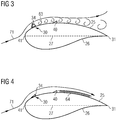
- Figure 3 shows the aerodynamic device 30 in a first protruded configuration, corresponding to an inflated configuration of the pneumatic actuator 34.
- the aerodynamic device 30 deviates the airflow 71 which is flowing from the leading edge 41 to the trailing edge 31 of the rotor blade.
- the aerodynamic device 30 in the first protruded configuration induces stall. This is visualized with relatively large vortices 63 downstream of the aerodynamic device 30. A consequence of the induced stall is a decrease in lift of the rotor blade and, consequently, a reduced loading of the rotor blade and related components of the wind turbine.
- Figure 4 shows the aerodynamic device 30 in a second retracted configuration, i.e. moved downwards towards the surface of the rotor blade 20, corresponding to a deflated configuration of the pneumatic actuator 34.
- the aerodynamic device 30 By operating the pneumatic actuator 34 of the aerodynamic device 30 through the pressure line 53, the aerodynamic device 30 can be moved between the first protruded configuration and the second retracted configuration in order to vary the aerodynamic properties of the blade as desired and requested when operating the wind turbine 10.
- Figure 5 schematically shows the pressure line 53 of the pressure supply system 52 connected to the pneumatic actuator 34 in the inflated configuration, to which corresponds the first protruded configuration of the aerodynamic device 30 (not shown in figure 5 ).
- the pressure line 53 extends between a first end 53a, where an acoustic transmitter 61 and an acoustic receiver 62 are provided, and a second end 53b connected to the pneumatic actuator 34 of the aerodynamic device 30.
- a sound absorption device 57 is provided at the first end 53a for acoustically isolating the first pressure line 53 from acoustical noise generated in other sections of the pressure supply system 52 not included in the first pressure line 53.
- the acoustic transmitter 61 and the acoustic receiver 62 are connected to a diagnostic unit 65.
- the acoustic transmitter 61 is a loudspeaker and the acoustic receiver 62 is a microphone.
- the diagnostic unit 65 is a sonar control unit.
- the first pressure line 53 and the actuator 34 in the inflated configuration provide a first path 68 for the acoustic signal.
- the first path 68 extends from the acoustic transmitter 61 through the first pressure line 53 through the second end 53b, up to a blind end 34a of the pneumatic actuator 34 and back towards the acoustic receiver 62.
- Figure 6 shows the same scheme of figure 5 , where the pneumatic actuator 34 is in the deflated configuration, to which corresponds the second retracted configuration of the aerodynamic device 30 (not shown in figure 6 ). Consequently, a second path 69 shorter than the first path 68 is provided for the acoustic signal.
- the second path 69 extends from the acoustic transmitter 61 through the first pressure line 53 up to the second end 53b and back towards the acoustic receiver 62.
- the diagnostic unit 65 is configured for deriving the operative status of the aerodynamic device 30 based on the analysis of the acoustic signal.
- the diagnostic unit 65 can derive if the pneumatic actuator 34 is in the inflated configuration ( figure 5 ) or in the deflated configuration ( figure 6 ). Consequently, the diagnostic unit 65 can derive if the aerodynamic device 30 is in the first protruded configuration or in the second retracted configuration.
- the analysis of the diagnostic unit 65 may be based on the comparison between the measured acoustic signal, in particular the measure time between emitted and received signal, and a desired acoustic signal, in particular the expected times between emitted and received signal when the pneumatic actuator 34 is in the inflated configuration or in the deflated configuration.
- the measured time does not correspond to the expected time, for example a time corresponding to a deflated configuration when an inflated configuration has been commanded through the pressure supply system 52 or vice versa, a failure of the pneumatic actuator 34 or of the aerodynamic device 30 is detected.
- FIG. 7 schematically shows another embodiment of the pressure supply system 52.
- the pressure line 53 of the pressure supply system 52 is connected to the pneumatic actuator 34 in the inflated configuration, to which corresponds the first protruded configuration of the aerodynamic device 30 (not shown in figure 7 ).
- the pressure line 53 extends between a first end 53a, where an acoustic transmitter 61 is provided, and a second end 53b connected to the pneumatic actuator 34 of the aerodynamic device 30.
- a sound absorption device 57 is provided at the first end 53a for acoustically isolating the first pressure line 53 from acoustical noise generated in other sections of the pressure supply system 52 not included in the first pressure line 53.
- the pressure supply system 52 includes a second pressure return line 58 for receiving the pressurized fluid from pneumatic actuator 34.
- the acoustic receiver 62 is provided at an end of the second pressure return line 58, opposite to the pneumatic actuator 34.
- the acoustic transmitter 61 and the acoustic receiver 62 are connected to a diagnostic unit 65.
- the first pressure line 53, the actuator 34 in the inflated configuration and the second pressure return line 58 provide a path for the acoustic signal from the acoustic transmitter 61 to the acoustic receiver 62.
- Figure 8 shows the same scheme of figure 7 , where the pneumatic actuator 34 is in the deflated configuration, to which corresponds the second retracted configuration of the aerodynamic device 30 (not shown in figure 6 ). Consequently, the path from the acoustic transmitter 61 to the acoustic receiver 62 is interrupted and an acoustic signal emitted from the acoustic transmitter 61 cannot be received by the acoustic receiver 62.
- the diagnostic unit 65 can derive if the pneumatic actuator 34 is in the inflated configuration ( figure 7 ) or in the deflated configuration ( figure 8 ). Consequently, the diagnostic unit 65 can derive if the aerodynamic device 30 is in the first protruded configuration or in the second retracted configuration.
- Figure 9 schematically shows the pressure line 53 of the pressure supply system 52 connected to the pneumatic actuator 34 in the inflated configuration, to which corresponds the first protruded configuration of the aerodynamic device 30 (not shown in figure 9 ).
- the pressure line 53 extends between a first end 53a, where an acoustic receiver 62 is provided, and a second end 53b connected to the pneumatic actuator 34 of the aerodynamic device 30.
- a sound absorption device 57 is provided at the first end 53a for acoustically isolating the first pressure line 53 from acoustical noise generated in other sections of the pressure supply system 52 not included in the first pressure line 53.
- the acoustic receiver 62 is connected to a diagnostic unit (not shown).
- the acoustic receiver 62 is a microphone.
- an acoustic source is provided by the wind acting on the aerodynamic device 30 and propagating to the pneumatic actuator 34 in the inflated configuration.
- the diagnostic unit is configured for calculating a frequency spectrum of the acoustic signal and deriving an operative status of the aerodynamic device 30 based on the frequency spectrum.
- the analysis of the diagnostic unit 65 is based on the comparison between the frequency spectrum of measured acoustic signal and a desired frequency spectrum, in particular the expected frequency spectrum when the pneumatic actuator 34 is in the inflated configuration or in the deflated configuration.
- the measured frequency spectrum does not correspond to the expected frequency spectrum, for example a frequency spectrum corresponding to a deflated configuration when an inflated configuration has been commanded through the pressure supply system 52 or vice versa, a failure of the pneumatic actuator 34 or of the aerodynamic device 30 is detected.
Landscapes
- Engineering & Computer Science (AREA)
- Life Sciences & Earth Sciences (AREA)
- Sustainable Development (AREA)
- Sustainable Energy (AREA)
- Chemical & Material Sciences (AREA)
- Combustion & Propulsion (AREA)
- Mechanical Engineering (AREA)
- General Engineering & Computer Science (AREA)
- Physics & Mathematics (AREA)
- Fluid Mechanics (AREA)
- Wind Motors (AREA)
Abstract
It is disclosed a wind turbine (10) including:
- at least a rotor blade (20) comprising an aerodynamic device (30) for influencing the airflow (71) flowing from the leading edge section (24) of the rotor blade (20) to the trailing edge section (23) of the rotor blade (20), wherein the aerodynamic device (30) is mounted at a surface (28) of the rotor blade (20),
- an actuator (34) of the aerodynamic device (30) for actuating the aerodynamic device (30) at least between a first protruded configuration and a second retracted configuration,
- a pressure supply system (52) for operating the actuator (34) by means of a pressurized fluid,
- an acoustic receiver (62) for measuring an acoustic signal in the pressure supply system (52), and
- a diagnostic unit (65) connected to the acoustic receiver (62) and configured for deriving an operative status of the aerodynamic device (30) based on the acoustic signal.
- at least a rotor blade (20) comprising an aerodynamic device (30) for influencing the airflow (71) flowing from the leading edge section (24) of the rotor blade (20) to the trailing edge section (23) of the rotor blade (20), wherein the aerodynamic device (30) is mounted at a surface (28) of the rotor blade (20),
- an actuator (34) of the aerodynamic device (30) for actuating the aerodynamic device (30) at least between a first protruded configuration and a second retracted configuration,
- a pressure supply system (52) for operating the actuator (34) by means of a pressurized fluid,
- an acoustic receiver (62) for measuring an acoustic signal in the pressure supply system (52), and
- a diagnostic unit (65) connected to the acoustic receiver (62) and configured for deriving an operative status of the aerodynamic device (30) based on the acoustic signal.
Description
- The present invention relates to a method for detecting the status in an aerodynamic device for regulating the flow on the surface of a blade for a wind turbine. The present invention further relates to a wind turbine including control devices for regulating the flow on the surface of a blade for a wind turbine and detecting the status aerodynamic device for regulating such flow.
- A wind turbine rotor blade may have installed a flow regulating device on its surface, which flows from the leading edge to the trailing edge of a rotor blade of a wind turbine. An example of such a flow regulating device is a vortex generator (VG) installed on the suction side of the wind turbine rotor blade. In general, a flow regulating device may be considered to comprise a device which is capable of enhancing the lift coefficient of the aerofoil section, for example by increasing the level of energy of the boundary layer of the rotor blade.
- Other aerodynamic devices may act in concert with the vortex generator and may influence the effect of the vortex generator depending on the state of the spoiler. Examples of the latter aerodynamic device are typically spoilers, installed on the suction side of the blade, between the trailing edge and the vortex generator. Alternatively, spoilers may be present alone, i.e. not combined with vortex generators or other flow regulating devices. Spoilers may be configured such that its shape and/or orientation can be regulated, e.g. by a pneumatic or hydraulic or mechanical actuator.
- The spoiler may act in concert with the vortex generator and may influence the effect of the vortex generator depending on the state of the spoiler, i.e. a protrusion height and/or tilt angle by which the spoiler extends from or is tilted relative to other surface portions of the rotor blade.
-
EP 1 623 111 B1 discloses a wind turbine blade including adjustable lift-regulating means arranged on or at the surface of the wind turbine blade and extending in the longitudinal direction of the blade and an activation means by which the lift-regulating means can be adjusted and thus alter the aerodynamic properties of the blade. The lift-regulating means comprise one or more flexible flaps. -
US 8 851 840 B2 discloses a wind turbine blade comprising a blade body and a device for modifying the aerodynamic surface or shape of the blade, wherein a pneumatic actuator controls the position and/or movement of the device, wherein a pressure chamber positioned within the blade body is present. The pressure chamber may be pressurized thereby changing the state of the device, thereby modifying the aerodynamic surface or shape of the blade. -
US 5 106 265 A discloses a wind turbine wing comprising a pneumatically actuated spoiler movable perpendicular to an airstream. -
WO 2018/041420 disclose a rotor blade comprising an aerodynamic device for influencing the air flow flowing from the leading edge section of the rotor blade to the trailing edge section of the rotor blade, wherein the aerodynamic device is mounted at a surface of the rotor blade and comprises a pneumatic or hydraulic actuator, such as a hose or a cavity of which the volume depends on the pressure of the fluid being present inside the pneumatic or hydraulic actuator.
EP 2 679 808 A1 shows a general description of the noise profile (frequency content) changing when the aerodynamic device is activated. - It is desirable to monitor the performance of the spoilers or other flow regulating aerodynamic devices regulated by a pneumatic or hydraulic actuator and their influence on the wind turbine power production.
- This need may be met by the subject matter according to the independent claims. Advantageous embodiments of the present invention are described by the dependent claims.
- According to a first aspect of the present invention, it is provided a wind turbine including:
- at least a rotor blade comprising an aerodynamic device for influencing the airflow flowing from the leading edge section of the rotor blade to the trailing edge section of the rotor blade, wherein the aerodynamic device is mounted at a surface of the rotor blade,
- an actuator of the aerodynamic device for actuating the aerodynamic device at least between a first protruded configuration and a second retracted configuration,
- a pressure supply system for operating the actuator by means of a pressurized fluid,
- an acoustic receiver for measuring an acoustic signal in the pressure supply system, and
- a diagnostic unit connected to the acoustic receiver and configured for deriving an operative status of the aerodynamic device based on the acoustic signal.
- According to a second aspect of the present invention, it is provided a method for detecting the operative status of an aerodynamic device for influencing the airflow flowing from the leading edge of a rotor blade for a wind turbine to the trailing edge of the rotor blade, the aerodynamic device being movable by an actuator between a first protruded configuration and a second retracted configuration by means of a pressurized fluid, the method comprising the steps of:
- measuring an acoustic signal in the pressure supply system, and
- deriving an operative status of the aerodynamic device based on the acoustic signal.
- The above described arrangement and method allow monitoring the performance and status of the aerodynamic device and therefore their influence on the wind turbine power production.
- Advantageously, the actuator may be a pneumatic hose connected to the pressure supply system. The pressure supply system operates the actuator by controlling the pressure in the pressurized fluid.
- According to embodiments of the present invention, the actuator, the pressure supply system, the acoustic receiver and the diagnostic unit are integrated in a rotor blade of the wind turbine.
- According to embodiments of the present invention, the wind turbine comprises an acoustic transmitter for transmitting the acoustic signal in the pressure supply system, the acoustic transmitter being connected to the diagnostic unit.
- The actuator may be operated between an inflated configuration corresponding to the first protruded configuration of the aerodynamic device and a deflated configuration corresponding to the second retracted configuration of the aerodynamic device, the actuator in the inflated configuration providing a first path for the acoustic signal in the pressure supply system, the actuator in the deflated configuration providing a second path for the acoustic signal in the pressure supply system, the second path being different from the first path.
- According to an embodiment of the present invention, the pressure supply system comprises a first pressure line for providing the pressurized fluid to the actuator of the aerodynamic device, the acoustic transmitter and the acoustic receiver being provided at the first pressure line.
- According to such embodiment, the diagnostic unit is a sonar control unit, the acoustic transmitter is a loudspeaker connected to the sonar control unit and the acoustic receiver is a microphone also connected to the sonar control unit. According to such embodiment, the loudspeaker injects a sound pulse into the pressure line. A microphone detects the echo. If the actuator is in the inflated configuration, the sound pulse travels to the end of the actuator before it echoes back to the microphone. If the actuator is in the deflated configuration the sound pulse is returned already at the end of the pressure line, i.e. at the closed port of the expander actuator. If the echo time is short, the actuator is in the deflated configuration; if the echo time is long, the actuator is in the inflated configuration.
- Advantageously, a sonar solution is failsafe; because in case there is a failure in the sonar system itself no echo is received.
- According to an embodiment of the present invention, a monitoring unit may be associated to the diagnostic unit for raising an alarm in case the received echo is not as expected.
- According to an embodiment of the present invention, the pressure supply system comprises a second pressure return line for receiving the pressurized fluid from the actuator of the aerodynamic device, the acoustic receiver being provided at the second pressure return line.
- According to such embodiment, the loudspeaker injects a sound pulse into the pressure line. The microphone is placed at the end of a return pressure line connected to the back end of the actuator. If the actuator is in the inflated configuration, the sound pulse travels all the way to the microphone. If the actuator is in the deflated configuration, the sound pulse stops at the end of the pressure line, i.e. at the beginning of the actuator.
- If a sound pulse is received, the actuator is in the inflated configuration and if no sound pulse is received, the actuator is in the deflated configuration.
- This information can be compared with the expected state of the trim stall section, and if there are deviations, an alarm is to be raised.
- According to an embodiment of the present invention, no acoustic transmitter is present, but the acoustic source is provided by the wind acting on the aerodynamic device and propagating to the pneumatic actuator in the inflated configuration.
- In such embodiment the diagnostic unit may be configured for calculating a frequency spectrum of the acoustic signal and deriving an operative status of the aerodynamic device based on the frequency spectrum.
- Such embodiment of the invention is based on the fact that aerodynamic device in the protruded configuration is subject to forces caused by the airflow around the blade. When stall will is generated the frequency of the stalled airflow propagates to the aerodynamic device and from there into the pneumatic actuator and the pressurized air used to actuate it. The vibration of this can be picked up by a microphone connected to the hose or directly as a vibration measurement on the section. If the aerodynamic device is in the retracted configuration, then these forces are must smaller and have different frequency content.
- According to an embodiment of the present invention, the first pressure line extends between a first end where the acoustic receiver and/or the acoustic transmitter are provided and a second end connected to the actuator of the aerodynamic device, a sound absorption device being provided at the first end for acoustically isolating the first pressure line from acoustical noise generated in the pressure supply system.
- Advantageously, the sound absorption material avoids that noise and echo from the pressure supply system reaches the pressure line.
- It should be understood that features which have individually or in any combination been disclosed, described or provided for a method for detecting the operative status of an aerodynamic device may also, individually or in any combination applied for or provided for an arrangement for detecting the operative status of an aerodynamic device in a wind turbine (in particular comprised in a blade for a wind turbine) according to embodiments of the present invention and vice versa
- The aspects defined above and further aspects of the present invention are apparent from the examples of embodiment to be described hereinafter and are explained with reference to the examples of embodiment. The invention will be described in more detail hereinafter with reference to examples of embodiment but to which the invention is not limited.
-
- Figure 1
- shows a wind turbine;
- Figure 2
- shows a rotor blade of a wind turbine including an aerodynamic device;
- Figures 3 and 4
- show a radial section of the rotor blade of
figure 2 ; - Figure 5 and 6
- shows schematically a pneumatic arrangement according to a first embodiment of the present invention;
- Figure 7 and 8
- shows schematically a pneumatic arrangement according to a second embodiment of the present invention;
- Figure 9
- shows schematically a pneumatic arrangement according to a third embodiment of the present invention.
- The drawings are in schematic form. Similar or identical elements are referenced by the same or different reference signs.
-
Figure 1 shows aconventional wind turbine 10 for generating electricity. Thewind turbine 10 comprises atower 11 which is mounted on theground 16 at one end. At the opposite end of thetower 11 there is mounted anacelle 12. Thenacelle 12 is usually mounted rotatable with regard to thetower 11, which is referred to as comprising a yaw axis substantially perpendicular to theground 16. Thenacelle 12 usually accommodates the generator of the wind turbine and the gear box (if the wind turbine is a geared wind turbine). Furthermore, thewind turbine 10 comprises ahub 13 which is rotatable about a rotor axis Y. When not differently specified, the terms axial, radial and circumferential in the following are made with reference to the rotor axis Y.
Thehub 13 is often described as being a part of a wind turbine rotor, wherein the wind turbine rotor is capable to rotate about the rotor axis Y and to transfer the rotational energy to an electrical generator (not shown). - The wind turbine 1 further comprises at least one blade 20 (in the embodiment of
Figure 1 , the wind rotor comprises threeblades 20, of which only twoblades 20 are visible) mounted on thehub 13. The blades 4 extend substantially radially with respect to the rotational axis Y.
Eachrotor blade 20 is usually mounted pivotable to thehub 13, in order to be pitched about respective pitch axes X. This improves the control of the wind turbine and in particular of the rotor blades by the possibility of modifying the direction at which the wind is hitting therotor blades 20. Eachrotor blade 20 is mounted to thehub 13 at itsroot section 21. Theroot section 21 is opposed to thetip section 22 of the rotor blade. -
Figure 2 illustrates therotor blade 20 comprising anaerodynamic device 30 in the form of an actuated spoiler. Between theroot section 21 and thetip section 22 therotor blade 20 furthermore comprises a plurality of aerofoil sections for generating lift. Each aerofoil section comprises asuction side 25 and apressure side 26. The aerofoil shape of the aerofoil portion is symbolized by one aerofoil profile which is shown inFigure 2 and which illustrates the cross-sectional shape of the rotor blade at this spanwise position. Also note that thesuction side 25 is divided or separated from thepressure side 26 by achord line 27 which connects aleading edge 41 with a trailingedge 31 of therotor blade 20. - The
aerodynamic device 30 is arranged on thesuction side 25 between theleading edge 41 and the trailingedge 31. - The
aerodynamic device 30 inFigure 2 is movable by means of apressure line 53 connected to apneumatic actuator 34. According to the embodiment of the attached figures, thepneumatic actuator 34 is realized as a hose. Thehose 34 comprises an elastic outer skin, such that it can inflate and deflate reversibly and during many cycles when operated by means of thepressure line 53. - The
pressure line 53 is comprised in apressure supply system 52, controlled by a control unit 51. Thepressure supply system 52 provides pressurized air, for example pressurized air or other pressurized gas, to thepneumatic actuator 34. In this context, the term "pressurized fluid" not only implies positive pressure but also negative pressure, wherein fluid is sucked (or "drawn") out of thepneumatic actuator 34. Thepressure line 53 could be in practice realized as tubes or pipes which do not significantly change their volume. Finally, the control unit 51 is responsible for setting a specific pressure at thepressure supply system 52 which subsequently leads to a certain predetermined pressure at thepneumatic actuator 34. By controlling the pressure of the pressurized air thepneumatic actuator 34 is operated between an inflated and a deflated configuration. - In the example shown in
Figure 2 , the control unit 51 and thepressure supply system 52 are located in theroot section 21 of therotor blade 20. According to other embodiments of the present invention (not shown in the attached figures), these parts could also be placed elsewhere in the wind turbine, such as e.g. in thehub 13 of thewind turbine 10. - The
rotor blade 20 additionally comprises aflow regulating unit 40 comprising multiple pairs of vortex generators. - The
flow regulating unit 40 are arranged on thesuction side 25 of theblade 20 between theaerodynamic device 30 and the the trailingedge 31. - According to other embodiments of the present invention (not shown in the attached figures), the
flow regulating unit 40 are arranged on thesuction side 25 of theblade 20 between theleading edge 41 and theaerodynamic device 30. - According to other embodiments of the present invention (not shown in the attached figures), the
flow regulating unit 40 are not present and only theaerodynamic device 30 is used to regulate the flow on the surface of theblade 20. - According to other embodiments of the present invention (not shown in the attached figures), the
blade 20 comprises a plurality ofaerodynamic devices 30. -
Figure 3 shows theaerodynamic device 30 in a first protruded configuration, corresponding to an inflated configuration of thepneumatic actuator 34. - In the first configuration the
aerodynamic device 30 deviates theairflow 71 which is flowing from the leadingedge 41 to the trailingedge 31 of the rotor blade. - The
aerodynamic device 30 in the first protruded configuration induces stall. This is visualized with relativelylarge vortices 63 downstream of theaerodynamic device 30. A consequence of the induced stall is a decrease in lift of the rotor blade and, consequently, a reduced loading of the rotor blade and related components of the wind turbine. -
Figure 4 shows theaerodynamic device 30 in a second retracted configuration, i.e. moved downwards towards the surface of therotor blade 20, corresponding to a deflated configuration of thepneumatic actuator 34. - In this second configuration, the
airflow 71 flowing across theaerodynamic device 30 remains attached to the surface of therotor blade 20, thus that no flow separation, i.e. stall, occurs. As a consequence, the lift of the rotor blade increases.Re-energizing vortices 64 are generated in the boundary layer by thevortex generators 40, which have the effect of helping increasing the lift. As a result, the highest lift values can be achieved. - By operating the
pneumatic actuator 34 of theaerodynamic device 30 through thepressure line 53, theaerodynamic device 30 can be moved between the first protruded configuration and the second retracted configuration in order to vary the aerodynamic properties of the blade as desired and requested when operating thewind turbine 10. -
Figure 5 schematically shows thepressure line 53 of thepressure supply system 52 connected to thepneumatic actuator 34 in the inflated configuration, to which corresponds the first protruded configuration of the aerodynamic device 30 (not shown infigure 5 ). Thepressure line 53 extends between afirst end 53a, where anacoustic transmitter 61 and anacoustic receiver 62 are provided, and asecond end 53b connected to thepneumatic actuator 34 of theaerodynamic device 30. Asound absorption device 57 is provided at thefirst end 53a for acoustically isolating thefirst pressure line 53 from acoustical noise generated in other sections of thepressure supply system 52 not included in thefirst pressure line 53. - The
acoustic transmitter 61 and theacoustic receiver 62 are connected to adiagnostic unit 65. - According to embodiments of the present invention, the
acoustic transmitter 61 is a loudspeaker and theacoustic receiver 62 is a microphone. - According to embodiments of the present invention, the
diagnostic unit 65 is a sonar control unit. - The
first pressure line 53 and theactuator 34 in the inflated configuration provide afirst path 68 for the acoustic signal. Thefirst path 68 extends from theacoustic transmitter 61 through thefirst pressure line 53 through thesecond end 53b, up to ablind end 34a of thepneumatic actuator 34 and back towards theacoustic receiver 62. -
Figure 6 shows the same scheme offigure 5 , where thepneumatic actuator 34 is in the deflated configuration, to which corresponds the second retracted configuration of the aerodynamic device 30 (not shown infigure 6 ). Consequently, asecond path 69 shorter than thefirst path 68 is provided for the acoustic signal. Thesecond path 69 extends from theacoustic transmitter 61 through thefirst pressure line 53 up to thesecond end 53b and back towards theacoustic receiver 62. - The
diagnostic unit 65 is configured for deriving the operative status of theaerodynamic device 30 based on the analysis of the acoustic signal. - By measuring the time between the emission of an acoustic signal from the
acoustic transmitter 61 and the reception of such signal by theacoustic receiver 62, thediagnostic unit 65 can derive if thepneumatic actuator 34 is in the inflated configuration (figure 5 ) or in the deflated configuration (figure 6 ). Consequently, thediagnostic unit 65 can derive if theaerodynamic device 30 is in the first protruded configuration or in the second retracted configuration. - The analysis of the
diagnostic unit 65 may be based on the comparison between the measured acoustic signal, in particular the measure time between emitted and received signal, and a desired acoustic signal, in particular the expected times between emitted and received signal when thepneumatic actuator 34 is in the inflated configuration or in the deflated configuration. - If the measured time does not correspond to the expected time, for example a time corresponding to a deflated configuration when an inflated configuration has been commanded through the
pressure supply system 52 or vice versa, a failure of thepneumatic actuator 34 or of theaerodynamic device 30 is detected. -
Figure 7 schematically shows another embodiment of thepressure supply system 52. Thepressure line 53 of thepressure supply system 52 is connected to thepneumatic actuator 34 in the inflated configuration, to which corresponds the first protruded configuration of the aerodynamic device 30 (not shown infigure 7 ). Thepressure line 53 extends between afirst end 53a, where anacoustic transmitter 61 is provided, and asecond end 53b connected to thepneumatic actuator 34 of theaerodynamic device 30. Asound absorption device 57 is provided at thefirst end 53a for acoustically isolating thefirst pressure line 53 from acoustical noise generated in other sections of thepressure supply system 52 not included in thefirst pressure line 53. - The
pressure supply system 52 includes a secondpressure return line 58 for receiving the pressurized fluid frompneumatic actuator 34. Theacoustic receiver 62 is provided at an end of the secondpressure return line 58, opposite to thepneumatic actuator 34. - The
acoustic transmitter 61 and theacoustic receiver 62 are connected to adiagnostic unit 65. - The
first pressure line 53, theactuator 34 in the inflated configuration and the secondpressure return line 58 provide a path for the acoustic signal from theacoustic transmitter 61 to theacoustic receiver 62. -
Figure 8 shows the same scheme offigure 7 , where thepneumatic actuator 34 is in the deflated configuration, to which corresponds the second retracted configuration of the aerodynamic device 30 (not shown infigure 6 ). Consequently, the path from theacoustic transmitter 61 to theacoustic receiver 62 is interrupted and an acoustic signal emitted from theacoustic transmitter 61 cannot be received by theacoustic receiver 62. - By detecting if the acoustic signal reaches the
acoustic receiver 62 or not, thediagnostic unit 65 can derive if thepneumatic actuator 34 is in the inflated configuration (figure 7 ) or in the deflated configuration (figure 8 ). Consequently, thediagnostic unit 65 can derive if theaerodynamic device 30 is in the first protruded configuration or in the second retracted configuration. - If such detection does not correspond to the expected one, for example a deflated configuration is detected when an inflated configuration has been commanded through the
pressure supply system 52 or vice versa, a failure of thepneumatic actuator 34 or of theaerodynamic device 30 is detected. -
Figure 9 schematically shows thepressure line 53 of thepressure supply system 52 connected to thepneumatic actuator 34 in the inflated configuration, to which corresponds the first protruded configuration of the aerodynamic device 30 (not shown infigure 9 ). Thepressure line 53 extends between afirst end 53a, where anacoustic receiver 62 is provided, and asecond end 53b connected to thepneumatic actuator 34 of theaerodynamic device 30. Asound absorption device 57 is provided at thefirst end 53a for acoustically isolating thefirst pressure line 53 from acoustical noise generated in other sections of thepressure supply system 52 not included in thefirst pressure line 53. - The
acoustic receiver 62 is connected to a diagnostic unit (not shown). - According to embodiments of the present invention, the
acoustic receiver 62 is a microphone. - In such embodiment an acoustic source is provided by the wind acting on the
aerodynamic device 30 and propagating to thepneumatic actuator 34 in the inflated configuration. - In the present embodiment the diagnostic unit is configured for calculating a frequency spectrum of the acoustic signal and deriving an operative status of the
aerodynamic device 30 based on the frequency spectrum. - The analysis of the
diagnostic unit 65 is based on the comparison between the frequency spectrum of measured acoustic signal and a desired frequency spectrum, in particular the expected frequency spectrum when thepneumatic actuator 34 is in the inflated configuration or in the deflated configuration. - If the measured frequency spectrum does not correspond to the expected frequency spectrum, for example a frequency spectrum corresponding to a deflated configuration when an inflated configuration has been commanded through the
pressure supply system 52 or vice versa, a failure of thepneumatic actuator 34 or of theaerodynamic device 30 is detected.
Claims (14)
- Wind turbine (10) including:- at least a rotor blade (20) comprising an aerodynamic device (30) for influencing the airflow (71) flowing from the leading edge section (24) of the rotor blade (20) to the trailing edge section (23) of the rotor blade (20), wherein the aerodynamic device (30) is mounted at a surface (28) of the rotor blade (20),- an actuator (34) of the aerodynamic device (30) for actuating the aerodynamic device (30) at least between a first protruded configuration and a second retracted configuration,- a pressure supply system (52) for operating the actuator (34) by means of a pressurized fluid,- an acoustic receiver (62) for measuring an acoustic signal in the pressure supply system (52), and- a diagnostic unit (65) connected to the acoustic receiver (62) and configured for deriving an operative status of the aerodynamic device (30) based on the acoustic signal.
- Wind turbine (10) according to claim 1, wherein the wind turbine (10) comprises an acoustic transmitter (61) for transmitting the acoustic signal in the pressure supply system (52), the acoustic transmitter (61) being connected to the diagnostic unit (65).
- Wind turbine (10) according to claim 1 or 2, wherein the actuator (34) is operated between an inflated configuration corresponding to the first protruded configuration of the aerodynamic device (30) and a deflated configuration corresponding to the second retracted configuration of the aerodynamic device (30), the actuator (34) in the inflated configuration providing a first path (68) for the acoustic signal in the pressure supply system (52), the actuator (34) in the deflated configuration providing a second path (69) for the acoustic signal in the pressure supply system (52), the second path (69) being different from the first path (68).
- Wind turbine (10) according to claim 2 or 3, wherein the pressure supply system (52) comprises at least a first pressure line (53) for providing the pressurized fluid to the actuator (34) of the aerodynamic device (30), the acoustic transmitter (61) being provided at the first pressure line (53) .
- Wind turbine (10) according to claim 4, wherein the pressure supply system (52) comprises at least a second pressure return line (58) for receiving the pressurized fluid from the actuator (34) of the aerodynamic device (30), the acoustic receiver (62) being provided at the second pressure return line (58).
- Wind turbine (10) according to claim 4 or 5, wherein the first pressure line (53) extends between a first end (53a) where the acoustic receiver (62) and/or the acoustic transmitter (61) are provided and a second end (53b) connected to the actuator (34) of the aerodynamic device (30), a sound absorption device (57) being provided at the first end (53a) for acoustically isolating the first pressure line (53) from acoustical noise generated in the pressure supply system (52) .
- Wind turbine (10) according to the any of the preceding claims, wherein the actuator (34) is an inflatable hose.
- Wind turbine (10) according to the any of the preceding claims, wherein the acoustic receiver (62) is a microphone.
- Wind turbine (10) according to the any of the preceding claims, wherein the acoustic transmitter (61) is a loudspeaker.
- Rotor blade (20) for a wind turbine (10) including:- an aerodynamic device (30) for influencing the airflow (71) flowing from the leading edge section (24) of the rotor blade (20) to the trailing edge section (23) of the rotor blade (20), wherein the aerodynamic device (30) is mounted at a surface (28) of the rotor blade (20),- an actuator (34) of the aerodynamic device (30) for actuating the aerodynamic device (30) at least between a first protruded configuration and a second retracted configuration,- a pressure supply system (52) for operating the actuator (34) by means of a pressurized fluid,- an acoustic receiver (62) for measuring an acoustic signal in the pressure supply system (52), and- a diagnostic unit (65) connected to the acoustic receiver (62) and configured for deriving an operative status of the aerodynamic device (30) based on the acoustic signal.
- Method for detecting the operative status of an aerodynamic device (30) for influencing the airflow (71) flowing from the leading edge (41) of a rotor blade (20) for a wind turbine (10) to the trailing edge (31) of the rotor blade (20), the aerodynamic device (30) being movable by an actuator (34) between a first protruded configuration and a second retracted configuration by means of a pressurized fluid, the method comprising the steps of:- measuring an acoustic signal in the pressure supply system (52), and- deriving an operative status of the aerodynamic device (30) based on the acoustic signal.
- Method according to claim 11, wherein the measured acoustic signal is compared with a desired acoustic signal, the operative status of the aerodynamic device (30) being derived based on the comparison between the measured acoustic signal and the desired acoustic signal.
- Method according to claim 11, the operative status of the aerodynamic device (30) being derived based on a time between the emission of the acoustic signal and the reception of the acoustic signal.
- Method according to claim 11, the method comprising the steps of:- calculating a frequency spectrum of the acoustic signal,- deriving an operative status of the aerodynamic device (30) based on the frequency spectrum.
Priority Applications (7)
| Application Number | Priority Date | Filing Date | Title |
|---|---|---|---|
| EP18212387.7A EP3667081A1 (en) | 2018-12-13 | 2018-12-13 | Wind turbine blade flow regulation |
| DK19801758.4T DK3867526T3 (en) | 2018-12-13 | 2019-10-31 | Regulation of wind turbine blade flow |
| CN201980082580.4A CN113167245A (en) | 2018-12-13 | 2019-10-31 | Wind turbine blade flow regulation |
| US17/311,009 US11428207B2 (en) | 2018-12-13 | 2019-10-31 | Wind turbine blade flow regulation |
| PCT/EP2019/079830 WO2020120014A1 (en) | 2018-12-13 | 2019-10-31 | Wind turbine blade flow regulation |
| ES19801758T ES2927616T3 (en) | 2018-12-13 | 2019-10-31 | Wind Turbine Blade Flow Regulation |
| EP19801758.4A EP3867526B1 (en) | 2018-12-13 | 2019-10-31 | Wind turbine blade flow regulation |
Applications Claiming Priority (1)
| Application Number | Priority Date | Filing Date | Title |
|---|---|---|---|
| EP18212387.7A EP3667081A1 (en) | 2018-12-13 | 2018-12-13 | Wind turbine blade flow regulation |
Publications (1)
| Publication Number | Publication Date |
|---|---|
| EP3667081A1 true EP3667081A1 (en) | 2020-06-17 |
Family
ID=64665467
Family Applications (2)
| Application Number | Title | Priority Date | Filing Date |
|---|---|---|---|
| EP18212387.7A Withdrawn EP3667081A1 (en) | 2018-12-13 | 2018-12-13 | Wind turbine blade flow regulation |
| EP19801758.4A Not-in-force EP3867526B1 (en) | 2018-12-13 | 2019-10-31 | Wind turbine blade flow regulation |
Family Applications After (1)
| Application Number | Title | Priority Date | Filing Date |
|---|---|---|---|
| EP19801758.4A Not-in-force EP3867526B1 (en) | 2018-12-13 | 2019-10-31 | Wind turbine blade flow regulation |
Country Status (6)
| Country | Link |
|---|---|
| US (1) | US11428207B2 (en) |
| EP (2) | EP3667081A1 (en) |
| CN (1) | CN113167245A (en) |
| DK (1) | DK3867526T3 (en) |
| ES (1) | ES2927616T3 (en) |
| WO (1) | WO2020120014A1 (en) |
Families Citing this family (1)
| Publication number | Priority date | Publication date | Assignee | Title |
|---|---|---|---|---|
| US12553413B2 (en) * | 2023-01-30 | 2026-02-17 | Siemens Gamesa Renewable Energy A/S | Wind turbine blade and wind turbine |
Citations (7)
| Publication number | Priority date | Publication date | Assignee | Title |
|---|---|---|---|---|
| US5106265A (en) | 1989-04-25 | 1992-04-21 | Astrid Holzem | Wind-turbine wing with a pneumatically actuated spoiler |
| EP1623111B1 (en) | 2003-05-05 | 2008-09-17 | Lm Glasfiber A/S | Wind turbine blade with lift-regulating means |
| EP2321528A2 (en) * | 2008-08-29 | 2011-05-18 | Vestas Wind Systems A/S | Control system in wind turbine blades |
| US20120086209A1 (en) * | 2010-10-06 | 2012-04-12 | Obrecht John M | System for remote monitoring of aerodynamic flow conditions |
| EP2679808A1 (en) | 2012-06-28 | 2014-01-01 | Siemens Aktiengesellschaft | Stall detection of wind turbine blades |
| DE102015117032A1 (en) * | 2015-10-07 | 2017-04-13 | Wobben Properties Gmbh | Method for monitoring a wind turbine |
| WO2018041420A1 (en) | 2016-08-30 | 2018-03-08 | Siemens Aktiengesellschaft | Flow control arrangement for a wind turbine rotor blade |
Family Cites Families (20)
| Publication number | Priority date | Publication date | Assignee | Title |
|---|---|---|---|---|
| FR2290585A1 (en) | 1974-11-07 | 1976-06-04 | Morin Bernard | Blade with variable profile for windmill rotor - has profile controlled by wind force and rotor speed |
| GB2157774A (en) | 1984-04-26 | 1985-10-30 | Lawson Tancred Sons & Company | Wind turbine blades |
| DK174261B1 (en) | 2000-09-29 | 2002-10-21 | Bonus Energy As | Device for use in regulating air flow around a wind turbine blade |
| US7777165B2 (en) * | 2007-02-02 | 2010-08-17 | Raytheon Company | Methods and apparatus for adjustable surfaces |
| US7901189B2 (en) * | 2007-05-14 | 2011-03-08 | General Electric Company | Wind-turbine blade and method for reducing noise in wind turbine |
| US20090097976A1 (en) * | 2007-10-15 | 2009-04-16 | General Electric Company | Active damping of wind turbine blades |
| GB2468693A (en) * | 2009-03-18 | 2010-09-22 | Vestas Wind Sys As | Wind turbine blade control |
| EP2476033B1 (en) * | 2009-09-08 | 2019-06-19 | Fraunhofer-Gesellschaft zur Förderung der angewandten Forschung e.V. | Model-based method for monitoring the condition of rotor blades |
| AU2010201622B1 (en) * | 2010-02-22 | 2011-07-21 | Mitsubishi Heavy Industries, Ltd. | Wind turbine generator and soundness diagnosis method thereof |
| US8327710B2 (en) * | 2010-07-29 | 2012-12-11 | General Electric Company | System for estimating a condition of non-conductive hollow structure exposed to a lightning strike |
| EP2565444B1 (en) * | 2011-08-31 | 2019-02-27 | Wölfel Engineering GmbH + Co. KG | Method and device for monitoring the status of rotor blades |
| US20120141271A1 (en) | 2011-09-13 | 2012-06-07 | General Electric Company | Actuatable spoiler assemblies for wind turbine rotor blades |
| EP2885531B1 (en) * | 2012-08-17 | 2017-03-29 | LM WP Patent Holding A/S | A blade deflection monitoring system |
| US9435320B2 (en) * | 2012-11-19 | 2016-09-06 | Elwha Llc | Mitigating wind turbine blade noise generation in view of a minimum power generation requirement |
| JP6250345B2 (en) * | 2013-09-24 | 2017-12-20 | Ntn株式会社 | Monitoring system and monitoring method |
| EP3249216B1 (en) * | 2016-05-27 | 2024-09-18 | Siemens Gamesa Renewable Energy A/S | Rotor blade with noise reduction means |
| DK3290688T3 (en) | 2016-08-30 | 2021-02-01 | Siemens Gamesa Renewable Energy As | Adjusting the rotational speed by changing the wing profile |
| DK3577339T3 (en) | 2017-03-07 | 2022-08-08 | Siemens Gamesa Renewable Energy As | Pressure supply system for a pneumatically actuable aerodynamic device of a rotor blade of a wind turbine |
| CN110582634A (en) | 2017-03-07 | 2019-12-17 | 西门子歌美飒可再生能源公司 | Safety system for aerodynamics of wind turbine rotor blades |
| EP3667063A1 (en) | 2018-12-13 | 2020-06-17 | Siemens Gamesa Renewable Energy A/S | Device for draining humidity in wind turbines |
-
2018
- 2018-12-13 EP EP18212387.7A patent/EP3667081A1/en not_active Withdrawn
-
2019
- 2019-10-31 DK DK19801758.4T patent/DK3867526T3/en active
- 2019-10-31 US US17/311,009 patent/US11428207B2/en active Active
- 2019-10-31 WO PCT/EP2019/079830 patent/WO2020120014A1/en not_active Ceased
- 2019-10-31 ES ES19801758T patent/ES2927616T3/en active Active
- 2019-10-31 CN CN201980082580.4A patent/CN113167245A/en active Pending
- 2019-10-31 EP EP19801758.4A patent/EP3867526B1/en not_active Not-in-force
Patent Citations (8)
| Publication number | Priority date | Publication date | Assignee | Title |
|---|---|---|---|---|
| US5106265A (en) | 1989-04-25 | 1992-04-21 | Astrid Holzem | Wind-turbine wing with a pneumatically actuated spoiler |
| EP1623111B1 (en) | 2003-05-05 | 2008-09-17 | Lm Glasfiber A/S | Wind turbine blade with lift-regulating means |
| EP2321528A2 (en) * | 2008-08-29 | 2011-05-18 | Vestas Wind Systems A/S | Control system in wind turbine blades |
| US8851840B2 (en) | 2008-08-29 | 2014-10-07 | Vestas Wind Systems A/S | Control system in wind turbine blades |
| US20120086209A1 (en) * | 2010-10-06 | 2012-04-12 | Obrecht John M | System for remote monitoring of aerodynamic flow conditions |
| EP2679808A1 (en) | 2012-06-28 | 2014-01-01 | Siemens Aktiengesellschaft | Stall detection of wind turbine blades |
| DE102015117032A1 (en) * | 2015-10-07 | 2017-04-13 | Wobben Properties Gmbh | Method for monitoring a wind turbine |
| WO2018041420A1 (en) | 2016-08-30 | 2018-03-08 | Siemens Aktiengesellschaft | Flow control arrangement for a wind turbine rotor blade |
Also Published As
| Publication number | Publication date |
|---|---|
| EP3867526B1 (en) | 2022-08-24 |
| US11428207B2 (en) | 2022-08-30 |
| WO2020120014A1 (en) | 2020-06-18 |
| US20220018329A1 (en) | 2022-01-20 |
| EP3867526A1 (en) | 2021-08-25 |
| DK3867526T3 (en) | 2022-09-12 |
| ES2927616T3 (en) | 2022-11-08 |
| CN113167245A (en) | 2021-07-23 |
Similar Documents
| Publication | Publication Date | Title |
|---|---|---|
| CN102459876B (en) | Wind turbine rotor blade | |
| CN110582635B (en) | Pressure supply system for pneumatically activatable pneumatics of a rotor blade of a wind turbine | |
| CN109996956A (en) | Flow control device for wind turbine rotor blades | |
| CN102741545B (en) | For the wind turbine blade of the rotor of wind turbine | |
| CN110582634A (en) | Safety system for aerodynamics of wind turbine rotor blades | |
| EP3870845B1 (en) | Damping vibrations in a wind turbine | |
| CN115667703A (en) | Rotor blade deflection control using a moving rotor blade attachment | |
| EP3907403A1 (en) | Rotor blade of a wind turbine comprising a lift modifying device and method for installing thereof | |
| EP3894698B1 (en) | Wind turbine blade flow regulation | |
| EP3867526B1 (en) | Wind turbine blade flow regulation | |
| EP4150209B1 (en) | Wind turbine blade comprising noise reduction means, wind turbine, and method for noise reduction for a wind turbine blade | |
| EP3667080A1 (en) | Wind turbine blade flow regulation | |
| EP3667065A1 (en) | Removing vibrations in wind turbine blades | |
| EP4100645B1 (en) | Aerodynamic load reduction during blade installation and service in a wind turbine | |
| EP3875752A1 (en) | Method and device for controlling a wind turbine to reduce noise | |
| EP3867521B1 (en) | Wind turbine | |
| EP3894694A1 (en) | Quick adaptation of wind turbine blade flow regulation | |
| EP3832127A1 (en) | Wind turbine blade flow regulation |
Legal Events
| Date | Code | Title | Description |
|---|---|---|---|
| PUAI | Public reference made under article 153(3) epc to a published international application that has entered the european phase |
Free format text: ORIGINAL CODE: 0009012 |
|
| STAA | Information on the status of an ep patent application or granted ep patent |
Free format text: STATUS: THE APPLICATION HAS BEEN PUBLISHED |
|
| AK | Designated contracting states |
Kind code of ref document: A1 Designated state(s): AL AT BE BG CH CY CZ DE DK EE ES FI FR GB GR HR HU IE IS IT LI LT LU LV MC MK MT NL NO PL PT RO RS SE SI SK SM TR |
|
| AX | Request for extension of the european patent |
Extension state: BA ME |
|
| STAA | Information on the status of an ep patent application or granted ep patent |
Free format text: STATUS: THE APPLICATION IS DEEMED TO BE WITHDRAWN |
|
| 18D | Application deemed to be withdrawn |
Effective date: 20201218 |