EP3667046B1 - Brennstoffbetätigungssystem - Google Patents
Brennstoffbetätigungssystem Download PDFInfo
- Publication number
- EP3667046B1 EP3667046B1 EP20153185.2A EP20153185A EP3667046B1 EP 3667046 B1 EP3667046 B1 EP 3667046B1 EP 20153185 A EP20153185 A EP 20153185A EP 3667046 B1 EP3667046 B1 EP 3667046B1
- Authority
- EP
- European Patent Office
- Prior art keywords
- fuel
- travel distance
- history
- actuation system
- pressure
- Prior art date
- Legal status (The legal status is an assumption and is not a legal conclusion. Google has not performed a legal analysis and makes no representation as to the accuracy of the status listed.)
- Active
Links
Images



Classifications
-
- G—PHYSICS
- G01—MEASURING; TESTING
- G01M—TESTING STATIC OR DYNAMIC BALANCE OF MACHINES OR STRUCTURES; TESTING OF STRUCTURES OR APPARATUS, NOT OTHERWISE PROVIDED FOR
- G01M15/00—Testing of engines
- G01M15/14—Testing gas-turbine engines or jet-propulsion engines
-
- F—MECHANICAL ENGINEERING; LIGHTING; HEATING; WEAPONS; BLASTING
- F01—MACHINES OR ENGINES IN GENERAL; ENGINE PLANTS IN GENERAL; STEAM ENGINES
- F01D—NON-POSITIVE DISPLACEMENT MACHINES OR ENGINES, e.g. STEAM TURBINES
- F01D21/00—Shutting-down of machines or engines, e.g. in emergency; Regulating, controlling, or safety means not otherwise provided for
- F01D21/003—Arrangements for testing or measuring
-
- F—MECHANICAL ENGINEERING; LIGHTING; HEATING; WEAPONS; BLASTING
- F02—COMBUSTION ENGINES; HOT-GAS OR COMBUSTION-PRODUCT ENGINE PLANTS
- F02C—GAS-TURBINE PLANTS; AIR INTAKES FOR JET-PROPULSION PLANTS; CONTROLLING FUEL SUPPLY IN AIR-BREATHING JET-PROPULSION PLANTS
- F02C7/00—Features, components parts, details or accessories, not provided for in, or of interest apart form groups F02C1/00 - F02C6/00; Air intakes for jet-propulsion plants
- F02C7/22—Fuel supply systems
- F02C7/232—Fuel valves; Draining valves or systems
-
- F—MECHANICAL ENGINEERING; LIGHTING; HEATING; WEAPONS; BLASTING
- F02—COMBUSTION ENGINES; HOT-GAS OR COMBUSTION-PRODUCT ENGINE PLANTS
- F02C—GAS-TURBINE PLANTS; AIR INTAKES FOR JET-PROPULSION PLANTS; CONTROLLING FUEL SUPPLY IN AIR-BREATHING JET-PROPULSION PLANTS
- F02C9/00—Controlling gas-turbine plants; Controlling fuel supply in air- breathing jet-propulsion plants
- F02C9/26—Control of fuel supply
- F02C9/263—Control of fuel supply by means of fuel metering valves
-
- F—MECHANICAL ENGINEERING; LIGHTING; HEATING; WEAPONS; BLASTING
- F05—INDEXING SCHEMES RELATING TO ENGINES OR PUMPS IN VARIOUS SUBCLASSES OF CLASSES F01-F04
- F05D—INDEXING SCHEME FOR ASPECTS RELATING TO NON-POSITIVE-DISPLACEMENT MACHINES OR ENGINES, GAS-TURBINES OR JET-PROPULSION PLANTS
- F05D2260/00—Function
- F05D2260/80—Diagnostics
Definitions
- This disclosure relates generally to gas turbine engines, and more particularly to systems and methods for monitoring the health of fuel actuation systems.
- Engine components and fittings may be subjected to relatively high temperatures. Once subjected to excessive heating, fuel may undergo coking. Coking may cause solid deposits to form within fuel flow paths, causing undesirable effects such as blocked passageways and filters. Furthermore, excessive heating, cyclic loading, and other harsh conditions of engine components may lead to degradation of component health. Accordingly, response time of fuel actuation components may retard beyond desirable limits.
- the present invention provides a fuel actuation system in accordance with claim 1.
- the present invention provides a method for monitoring fuel actuation system health in accordance with claim 4.
- the present invention provides an electronic engine control (EEC) in accordance with claim 10.
- EEC electronic engine control
- Gas turbine engine 120 may be a two-spool turbofan that generally incorporates a fan section 122, a compressor section 124, a combustor section 126 and a turbine section 128.
- Alternative engines may include, for example, an augmentor section among other systems or features.
- fan section 122 can drive air along a bypass flow-path B while compressor section 124 can drive air along a core flow-path C for compression and communication into combustor section 126 then expansion through turbine section 128.
- turbofan gas turbine engine 120 depicted as a turbofan gas turbine engine 120 herein, it should be understood that the concepts described herein are not limited to use with turbofans as the teachings may be applied to other types of turbine engines including three-spool architectures.
- Gas turbine engine 120 may generally comprise a low speed spool 130 and a high speed spool 132 mounted for rotation about an engine central longitudinal axis A-A' relative to an engine static structure 136 via one or more bearing systems 138 (shown as bearing system 138-1 and bearing system 138-2 in FIG. 1 ). It should be understood that various bearing systems 138 at various locations may alternatively or additionally be provided including, for example, bearing system 138, bearing system 138-1, and bearing system 138-2.
- a combustor 156 may be located between HPC 152 and high pressure turbine 154.
- a mid-turbine frame 157 of engine static structure 136 may be located generally between high pressure turbine 154 and low pressure turbine 146.
- Mid-turbine frame 157 may support one or more bearing systems 138 in turbine section 128.
- Inner shaft 140 and outer shaft 150 may be concentric and rotate via bearing systems 138 about the engine central longitudinal axis A-A', which is collinear with their longitudinal axes.
- a "high pressure" compressor or turbine experiences a higher pressure than a corresponding "low pressure” compressor or turbine.
- the core airflow C may be compressed by low pressure compressor 144 then HPC 152, mixed and burned with fuel in combustor 156, then expanded over high pressure turbine 154 and low pressure turbine 146.
- Mid-turbine frame 157 includes airfoils 159 which are in the core airflow path.
- Low pressure turbine 146 and high pressure turbine 154 rotationally drive the respective low speed spool 130 and high speed spool 132 in response to the expansion.
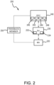
- Fuel actuation system 200 is illustrated in accordance with various embodiments.
- Gas turbine engine 120 may be operatively connected to fuel actuation system 200.
- Fuel actuation system 200 may include electronic engine control (EEC) 240, servo valve (SV) 230, metering valve (MV) 220, and/or feedback member 250.
- EEC electronic engine control
- SV servo valve
- MV metering valve
- EEC 240 may control fuel delivery to combustor 156.
- EEC 240 may be operatively connected to SV 230 having a torque motor 232 that is selectively activated to control fuel delivery to MV 220.
- SV 230 may comprise a single stage servo valve. However, SV 230 may comprise any suitable servo valve.
- SV 230 may be fluidly connected to MV 220.
- SV 230 may also include one or more screens 234 that prevent contaminate from entering the fuel used to control MV 220. It should be understood that screens 234 may also be located in an adjacent fuel control component.
- EEC 240 may control torque motor 232 to cause SV 230 to deliver fuel to MV 220 to establish a set point which defines a desired fuel burn flow rate to combustor 156.
- EEC 240 is shown to include a feedback member 250.
- Feedback member 250 may provide position feedback from MV 220 to EEC 240.
- Feedback member 250 may provide temperature feedback from MV 220 to EEC 240.
- Feedback member 250 may provide pressure feedback from MV 220 to EEC 240.
- feedback member 250 may include a temperature sensor, a pressure sensor, and/or a position sensor.
- processing circuitry 142 may include any combination of processing circuits known in the art, such as one or more microprocessors, microcontrollers, digital signal processors, and/or programmable logic devices.
- the memory 244 may store executable instructions and data to implement control logic of EEC 240.
- Memory 244 may comprise a tangible, non-transitory storage medium and may store data used, for example, in trending and prognosis purposes.
- EEC 240 may also include an SV interface 248 that converts data from SV 230 into a format usable by processing circuitry 142 such as a frequency-to-digital converter, for example.
- EEC 240 may further include a feedback member interface 246 that receives signals from feedback member 250 which provides an indication of MV 220 opening as set by torque motor 232 and also provides a pathway for EEC 240 to control torque motor 232 to set a new valve opening for MV 220.
- EEC 240 may source a controlled amount of current to torque motor 232 as a metering valve control signal.
- MV 220 is generally actuated or moved via hydraulic or fueldraulic pressure.
- a hydraulic system such as a fuel system, may be in fluidic communication with SV 230.
- Torque motor 232 of SV 230 may receive current from a power source, such as EEC 240 for example, to move a moveable member of SV 230 and in response to the moving, a controlled hydraulic pressure is supplied to MV 220.
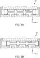
- a metering valve 600 is illustrated, in accordance with various embodiments.
- metering valve 220 may be similar to metering valve 600.
- Metering valve 600 may comprise a moveable member 602.
- Moveable member 602 is illustrated in FIG. 6A in a first position. Although illustrated in FIG. 6A as being in a particular position, the first position of moveable member 602 may any suitable position including a closed or open position.
- a metering valve 600 is illustrated, in accordance with various embodiments.
- Moveable member 602 is illustrated in FIG. 6B in a second position. Although illustrated in FIG. 6B as being in a particular position, the second position of moveable member 602 may any suitable position including a closed or open position.
- the health of fuel actuation system 200 may be monitored via EEC 240.
- System parameters such as time of travel of MV 220, fuel temperature, and fuel pressure may be sensed by feedback member 250 and stored into memory 244.
- a history of these system parameters may be trended and analyzed by EEC 240 to determine a diagnosis as well as a prognosis of the health of fuel actuation system 200.
- a method 300 for monitoring the health of fuel actuation system 200 is provided, in accordance with various embodiments.
- Method 300 may include moving MV 220 from a first position to a second position (see step 301). MV 220 may be moved via any suitable method.
- MV 220 may be moved by increasing or decreasing current supplied to SV 230.
- a travel time may be detected when MV 220 is moved from the first position to the second position (see step 302).
- the travel time may be the total duration of time that it takes for MV 220 to move from the first position to the second position.
- the travel time may be stored to memory 244 (see step 303). Accordingly, over time, multiple travel times may be stored to memory, thus generating a historical trend of travel times or a travel time history.
- a controller such as EEC 240, may determine the health of fuel actuation system 200 based on the travel time history (see step 304).
- the health of fuel actuation system 200 may be based on a level of degradation of the fuel actuation system 200.
- the health of fuel actuation system 200 may be based on a level of degradation of the travel time of MV 220.
- Method 310 may include moving MV 220 from a first position to a second position for a pre-determined duration (see step 311).
- MV 220 may be moved via any suitable method.
- MV 220 may be moved by increasing or decreasing current supplied to SV 230.
- a travel distance may be detected when MV 220 is moved from the first position to the second position (see step 312).
- the travel distance may be the distance between the first position and the second position.
- the travel distance may be stored to memory 244 (see step 313).
- a controller such as EEC 240, may determine the health of fuel actuation system 200 based on the travel distance history (see step 314).
- the health of fuel actuation system 200 may be based on a level of degradation of the fuel actuation system 200.
- the health of fuel actuation system 200 may be based on a level of degradation of the travel distance of MV 220.
- a plot 500 of travel time 502 is plotted verses time. Travel time 502 may decrease over time and degradation 504 of travel time 502 may occur. Degradation 504 may be the difference between initial travel time 506 and travel time 502. Thus, degradation 504 may be a change in travel time 502. In various embodiments, degradation 504 may vary over time. In various embodiments, degradation 504 may increase over time. Although some degradation 504 of travel time 502 might be expected, excessive decrease in travel time 502 may indicate poor health of fuel actuation system 200 (see FIG. 2 ). Accordingly, plot 500 illustrates a travel time history. Although illustrated with respect to travel time, plot 500 may also similarly illustrate a degradation of travel distance over time. Stated another way, travel time may be replaced with travel distance in FIG. 5 to similarly illustrated travel distance in inches or centimeters. In this manner a travel distance history may be created.
- Method 400 may include detecting an engine shutdown (see step 401). Detecting an engine shutdown may include at least one of determining if an aircraft is on the ground, determining if an engine is at ground idle, and determining if an overspeed test is successful. With further reference to FIG. 2 , method 400 may include moving MV 220 from a first position to a second position (see step 402). Step 402 may be similar to step 301 (see FIG. 3A ) and/or step 311 (see FIG. 3B ).
- At least one of a travel time, a travel distance, a fuel temperature, or a fuel pressure may be detected when MV 220 is moved from the first position to the second position (see step 403).
- the travel time may be the total duration of time that it takes for MV 220 to move from the first position to the second position.
- the travel distance may be the distance between the first position to the second position.
- the fuel temperature may be the temperature of a fuel located in fuel actuation system 200.
- Fuel temperature may be detected via a temperature sensor of feedback member 250.
- the fuel pressure may be a pressure of a fuel located in fuel actuation system 200.
- Fuel pressure may be detected via a pressure sensor of feedback member 250.
- fuel pressure may be determined via any suitable method.
- the travel time, travel distance, fuel temperature, and/or fuel pressure may be stored to memory 244 (see step 404). Similar to the travel time 502 (see FIG. 5 ), the travel distance, the fuel temperatures, and the fuel pressures may be stored to memory, thus generating, over time, travel distance trends, fuel temperature trends, and fuel pressure trends, or travel distance history, fuel temperature history, and fuel pressure history.
- the MV 220 may be moved from the second position to a third position (see step 405).
- the second position may be an open position.
- the third position may be a closed position.
- the second position and the third position may comprise any suitable position.
- At least one of a second travel time, a second travel distance, a second fuel temperature, or a second fuel pressure may be detected when MV 220 is moved from the second position to the third position (see step 406).
- a controller such as EEC 240, may determine a level of degradation of the fuel actuation system 200 based on the travel time history and/or the travel distance history.
- a controller such as EEC 240, may determine a level of degradation of the fuel actuation system 200 based on the travel distance history in a manner similar to the travel time history.
- a controller, such as EEC 240 may determine a level of degradation of the fuel actuation system 200 based on the fuel temperature history in a manner similar to the travel time history.
- a controller such as EEC 240 may determine a level of degradation of the fuel actuation system 200 based on the fuel pressure history in a manner similar to the travel time history. Accordingly, A controller, such as EEC 240, may determine the health of fuel actuation system 200 (see step 407). In various embodiments, EEC 240 may indicate the determined system health (see step 408). For example, EEC 240 may output a signal to a display to indicate the health of fuel actuation system 200. Such indication may be performed via any suitable indicator such as, for example, a light, a message on a display, text, symbols, etc. For example, EEC 240 may output a signal to a display or other controller to indicate the degradation or health of fuel actuation system 200.
- the health of a system may be determined by comparing the degradation 504 of one system, with the degradation of one or more other systems.
- one system may comprise a degradation which is compared with the average degradation of a group of systems.
Landscapes
- Engineering & Computer Science (AREA)
- Chemical & Material Sciences (AREA)
- Combustion & Propulsion (AREA)
- Mechanical Engineering (AREA)
- General Engineering & Computer Science (AREA)
- Physics & Mathematics (AREA)
- General Physics & Mathematics (AREA)
- Control Of Turbines (AREA)
- Combined Controls Of Internal Combustion Engines (AREA)
- Testing And Monitoring For Control Systems (AREA)
Claims (10)
- Brennstoffbetätigungssystem (200), umfassend:ein Servoventil (SV) (230), das einen Drehmomentmotor (232) und mindestens einen Sieb (234) beinhaltet;ein Dosierventil (MV) (220; 600), das mit dem SV (230) fluidverbunden ist; undeine elektronische Triebwerkssteuerung (EEC) (240), die mit dem SV (230) wirkverbunden ist, wobei die EEC (200) zu Folgendem konfiguriert und angeordnet ist:Bestimmen einer Verfahrdistanz des MV (220; 600) und mindestens eines von einem Druck eines Brennstoffs und einer Temperatur des Brennstoffs; undSpeichern der Verfahrdistanz des MV (220; 600) und des mindestens einem von dem Druck eines Brennstoffs und der Temperatur des Brennstoffs in einem Speicher (244), um einen Verfahrdistanzverlauf und mindestens eines von einem Brennstofftemperaturverlauf und einem Brennstoffdruckverlauf zu erzeugen,dadurch gekennzeichnet, dass die EEC (200) ferner zu Folgendem konfiguriert und angeordnet ist:
Bestimmen eines Verschlechterungsgrads des Brennstoffbetätigungssystems (200) basierend auf dem Verfahrdistanzverlauf und dem mindestens einem von dem Brennstofftemperaturverlauf und dem Brennstoffdruckverlauf. - Brennstoffbetätigungssystem nach Anspruch 1, wobei der Verschlechterungsgrad eine Änderung der Verfahrdistanz und mindestens eines von einer Änderung des Drucks des Brennstoffs und einer Änderung der Temperatur des Brennstoffs beinhaltet.
- Brennstoffbetätigungssystem nach Anspruch 1 oder 2, wobei die Verfahrdistanz des MV (220; 600) durch Bewegen des MV (220; 600) für eine vorbestimmte Dauer bestimmt wird.
- Verfahren zum Überwachen des Zustands des Brennstoffbetätigungssystems (200), umfassend:Bewirken, dass sich ein Dosierventil (220; 600) von einer ersten Position in eine zweite Position bewegt;Erfassen einer ersten Verfahrdistanz des Dosierventils (220; 600);Speichern der ersten Verfahrdistanz des Dosierventils (220; 600) in einem Speicher (244), um einen ersten Verfahrdistanzverlauf zu erzeugen; und gekennzeichnet durchErfassen mindestens eines von einer Temperatur eines Brennstoffs oder einem Druck des Brennstoffs;Speichern des mindestens einem von der Temperatur des Brennstoffs oder dem Druck des Brennstoffs in dem Speicher (244), um mindestens eines von einem Brennstofftemperaturverlauf oder einem Brennstoffdruckverlauf zu erstellen;Bestimmen eines Verschlechterungsgrads eines Brennstoffbetätigungssystems (200) basierend auf mindestens dem ersten Verfahrdistanzverlauf und mindestens einem von dem Brennstofftemperaturverlauf oder dem Brennstoffdruckverlauf; undAusgeben eines Signals an eine Anzeige, um den Verschlechterungsgrad des Brennstoffbetätigungssystems anzugeben.
- Verfahren nach Anspruch 4, ferner umfassend:Bewirken, dass sich das Dosierventil (220; 600) von der zweiten Position in eine dritte Position bewegt;Erfassen einer zweiten Verfahrdistanz des Dosierventils (220; 600);Speichern der zweiten Verfahrdistanz des Dosierventils (220; 600) in dem Speicher (244), um einen zweiten Verfahrdistanzverlauf zu erzeugen;Bestimmen des Verschlechterungsgrads des Brennstoffbetätigungssystems (200) basierend auf mindestens einem von dem ersten Verfahrdistanzverlauf und dem zweiten Verfahrdistanzverlauf.
- Verfahren nach Anspruch 4 oder 5, wobei der Verschlechterungsgrad mindestens eines von einer Änderung der ersten Verfahrdistanz, einer Änderung des Drucks des Brennstoffs oder einer Änderung der Temperatur des Brennstoffs beinhaltet.
- Verfahren nach einem der Ansprüche 4 bis 6, ferner umfassend Erfassen einer Triebwerksabschaltung.
- Verfahren nach Anspruch 7, wobei das Erfassen der Triebwerksabschaltung mindestens eines von Bestimmen, ob sich ein Flugzeug am Boden befindet, Bestimmen, ob sich ein Triebwerk im Leerlauf befindet, und Bestimmen, ob ein Überdrehzahltest erfolgreich war, beinhaltet.
- Verfahren nach einem der Ansprüche 4 bis 8, wobei das Bewirken, dass sich das Dosierventil (220; 600) bewegt, mindestens eines von Erhöhen oder Verringern des Stroms zu einem Servoventil (SV) (230) für eine vorbestimmte Dauer beinhaltet.
- Elektronische Triebwerkssteuerung (EEC) (240), umfassend:eine Steuerung; undeinen physischen, nichttransitorischen Speicher, der dazu konfiguriert ist, mit der Steuerung zu kommunizieren, wobei in dem physischen, nichttransitorischen Speicher Anweisungen gespeichert sind, die als Reaktion auf die Ausführung durch die Steuerung bewirken, dass die Steuerung Operationen gemäß dem Verfahren nach einem der Ansprüche 4 bis 9 durchführt.
Applications Claiming Priority (2)
| Application Number | Priority Date | Filing Date | Title |
|---|---|---|---|
| US15/017,138 US9983096B2 (en) | 2016-02-05 | 2016-02-05 | Fuel metering valve actuator initiated built in test |
| EP17154659.1A EP3236048B1 (de) | 2016-02-05 | 2017-02-03 | Verfahren zur überwachung des zustandes eines brennstoffzumesssystems und eec |
Related Parent Applications (2)
| Application Number | Title | Priority Date | Filing Date |
|---|---|---|---|
| EP17154659.1A Division-Into EP3236048B1 (de) | 2016-02-05 | 2017-02-03 | Verfahren zur überwachung des zustandes eines brennstoffzumesssystems und eec |
| EP17154659.1A Division EP3236048B1 (de) | 2016-02-05 | 2017-02-03 | Verfahren zur überwachung des zustandes eines brennstoffzumesssystems und eec |
Publications (2)
| Publication Number | Publication Date |
|---|---|
| EP3667046A1 EP3667046A1 (de) | 2020-06-17 |
| EP3667046B1 true EP3667046B1 (de) | 2025-03-26 |
Family
ID=57963134
Family Applications (2)
| Application Number | Title | Priority Date | Filing Date |
|---|---|---|---|
| EP20153185.2A Active EP3667046B1 (de) | 2016-02-05 | 2017-02-03 | Brennstoffbetätigungssystem |
| EP17154659.1A Active EP3236048B1 (de) | 2016-02-05 | 2017-02-03 | Verfahren zur überwachung des zustandes eines brennstoffzumesssystems und eec |
Family Applications After (1)
| Application Number | Title | Priority Date | Filing Date |
|---|---|---|---|
| EP17154659.1A Active EP3236048B1 (de) | 2016-02-05 | 2017-02-03 | Verfahren zur überwachung des zustandes eines brennstoffzumesssystems und eec |
Country Status (2)
| Country | Link |
|---|---|
| US (2) | US9983096B2 (de) |
| EP (2) | EP3667046B1 (de) |
Families Citing this family (9)
| Publication number | Priority date | Publication date | Assignee | Title |
|---|---|---|---|---|
| DE102018214923A1 (de) * | 2018-09-03 | 2020-03-05 | Rolls-Royce Deutschland Ltd & Co Kg | Überwachung von Servoventil-Filterelementen |
| US10975777B2 (en) * | 2018-10-01 | 2021-04-13 | Hamilton Sunstrand Corporation | Fuel metering unit |
| FR3092170B1 (fr) * | 2019-01-24 | 2022-08-19 | Safran Helicopter Engines | Procédé de surveillance de l’état de fonctionnement d’un système de positionnement d’organes à géométrie variable d’une turbomachine |
| RU2706829C1 (ru) * | 2019-02-07 | 2019-11-21 | Публичное акционерное общество "ОДК-Уфимское моторостроительное производственное объединение" (ПАО "ОДК-УМПО") | Стенд для комплексных испытаний двигательных и самолетных агрегатов газотурбинного двигателя |
| FR3117457B1 (fr) * | 2020-12-16 | 2023-04-21 | Safran Aircraft Engines | Procédé et système de détection de l’usure d’un vérin |
| US12203419B2 (en) * | 2022-11-29 | 2025-01-21 | Woodward, Inc. | System and method for in situ verification of redundant electro-hydraulic servo valve (EHSV) operational status in redundant flow control systems |
| US12345211B2 (en) | 2023-08-21 | 2025-07-01 | Rolls-Royce North American Technologies, Inc. | Uncommanded or uncontrollable high thrust detection and mitigation |
| US12258911B2 (en) * | 2023-08-21 | 2025-03-25 | Rolls-Royce Corporation | Fuel unit health monitoring system |
| US20260110265A1 (en) * | 2024-10-18 | 2026-04-23 | Pratt & Whitney Canada Corp. | Fuel metering valve performance shift check function |
Family Cites Families (3)
| Publication number | Priority date | Publication date | Assignee | Title |
|---|---|---|---|---|
| GB0526330D0 (en) | 2005-12-23 | 2006-02-01 | Rolls Royce Plc | Engine health monitoring |
| US8720201B2 (en) * | 2010-11-24 | 2014-05-13 | Hamilton Sundstrand Corporation | Method of monitoring an electronic engine control (EEC) to detect a loss of fuel screen open area |
| FR2983529B1 (fr) | 2011-12-05 | 2014-01-17 | Snecma | Methode de surveillance d’un dispositif de commande d’un doseur de carburant d’un turboreacteur |
-
2016
- 2016-02-05 US US15/017,138 patent/US9983096B2/en active Active
-
2017
- 2017-02-03 EP EP20153185.2A patent/EP3667046B1/de active Active
- 2017-02-03 EP EP17154659.1A patent/EP3236048B1/de active Active
-
2018
- 2018-04-30 US US15/967,192 patent/US10379003B2/en active Active
Also Published As
| Publication number | Publication date |
|---|---|
| US10379003B2 (en) | 2019-08-13 |
| EP3236048B1 (de) | 2020-04-01 |
| US9983096B2 (en) | 2018-05-29 |
| EP3667046A1 (de) | 2020-06-17 |
| EP3236048A1 (de) | 2017-10-25 |
| US20170227424A1 (en) | 2017-08-10 |
| US20180246012A1 (en) | 2018-08-30 |
Similar Documents
| Publication | Publication Date | Title |
|---|---|---|
| EP3667046B1 (de) | Brennstoffbetätigungssystem | |
| US12180892B2 (en) | Machine learned aero-thermodynamic engine inlet condition synthesis | |
| EP3159500B1 (de) | Hilfspumpe und gasturbinenmotorölkreislaufüberwachungssystem | |
| EP3205835B1 (de) | Start eines gebogenen rotors mit direkter temperaturmessung | |
| EP3196616B1 (de) | Wärmeflussmesssystem | |
| EP3293385B1 (de) | Gasturbinentriebwerk mit progressiver strömungsabrisswiederherstellung | |
| US8869603B2 (en) | Debris detection in turbomachinery and gas turbine engines | |
| US11339678B2 (en) | Systems and methods for controlling blade tip clearances | |
| JP2016176472A (ja) | ガスタービンエンジンの健全性の算出 | |
| EP3276439B2 (de) | System und verfahren zur beurteilung des zustands einer ersten vorrichtung durch überwachung einer abhängigen zweiten vorrichtung | |
| US9810091B2 (en) | Smart active clearance control between a rotor blade and a shroud | |
| EP3208447B1 (de) | System und verfahren zur berechnung eines brennstofflackierungsindexes | |
| US20070051111A1 (en) | System and method for lightoff detection in turbine engines | |
| US11726859B2 (en) | Switchover for redundant control systems | |
| EP3409927B1 (de) | Transiente regelung zur verlängerung der lebensdauer eines gasturbinenmotors | |
| EP3014089B1 (de) | Übermässige verformungsüberwachung anhand eines lüfterantriebssystems | |
| EP2955511A1 (de) | In-situ-system und verfahren zur bestimmung der beschichtungsintegrität von turbomaschinenkomponenten | |
| EP3321475B1 (de) | Ölrückstandsüberwachung mit aktiver ventilkonfigurationssteuerung | |
| US11326468B2 (en) | Methods and systems for operating a gas turbine engine | |
| EP2458179B1 (de) | Verfahren zur Überwachung einer elektronischen Motorsteuerung zur Erkennung der Verschmutzung eines Kraftstofffilters | |
| US12085028B2 (en) | Method and device for detecting a rotating stall adversely affecting a turbojet engine compressor | |
| CA3044429C (fr) | Procede de commande d'une vanne de turbomachine |
Legal Events
| Date | Code | Title | Description |
|---|---|---|---|
| PUAI | Public reference made under article 153(3) epc to a published international application that has entered the european phase |
Free format text: ORIGINAL CODE: 0009012 |
|
| STAA | Information on the status of an ep patent application or granted ep patent |
Free format text: STATUS: THE APPLICATION HAS BEEN PUBLISHED |
|
| AC | Divisional application: reference to earlier application |
Ref document number: 3236048 Country of ref document: EP Kind code of ref document: P |
|
| AK | Designated contracting states |
Kind code of ref document: A1 Designated state(s): AL AT BE BG CH CY CZ DE DK EE ES FI FR GB GR HR HU IE IS IT LI LT LU LV MC MK MT NL NO PL PT RO RS SE SI SK SM TR |
|
| RIN1 | Information on inventor provided before grant (corrected) |
Inventor name: HETTLER, ERIC N. Inventor name: MCCORMICK, KEVIN P. Inventor name: GRACE, AMY R. Inventor name: MARTUCCI, ANGELO Inventor name: BUSH, THOMAS A. Inventor name: DONAT, WILLIAM |
|
| STAA | Information on the status of an ep patent application or granted ep patent |
Free format text: STATUS: REQUEST FOR EXAMINATION WAS MADE |
|
| 17P | Request for examination filed |
Effective date: 20201217 |
|
| RBV | Designated contracting states (corrected) |
Designated state(s): AL AT BE BG CH CY CZ DE DK EE ES FI FR GB GR HR HU IE IS IT LI LT LU LV MC MK MT NL NO PL PT RO RS SE SI SK SM TR |
|
| RAP1 | Party data changed (applicant data changed or rights of an application transferred) |
Owner name: RAYTHEON TECHNOLOGIES CORPORATION |
|
| STAA | Information on the status of an ep patent application or granted ep patent |
Free format text: STATUS: EXAMINATION IS IN PROGRESS |
|
| 17Q | First examination report despatched |
Effective date: 20220914 |
|
| RAP3 | Party data changed (applicant data changed or rights of an application transferred) |
Owner name: RTX CORPORATION |
|
| GRAP | Despatch of communication of intention to grant a patent |
Free format text: ORIGINAL CODE: EPIDOSNIGR1 |
|
| STAA | Information on the status of an ep patent application or granted ep patent |
Free format text: STATUS: GRANT OF PATENT IS INTENDED |
|
| INTG | Intention to grant announced |
Effective date: 20240919 |
|
| GRAS | Grant fee paid |
Free format text: ORIGINAL CODE: EPIDOSNIGR3 |
|
| GRAA | (expected) grant |
Free format text: ORIGINAL CODE: 0009210 |
|
| STAA | Information on the status of an ep patent application or granted ep patent |
Free format text: STATUS: THE PATENT HAS BEEN GRANTED |
|
| AC | Divisional application: reference to earlier application |
Ref document number: 3236048 Country of ref document: EP Kind code of ref document: P |
|
| AK | Designated contracting states |
Kind code of ref document: B1 Designated state(s): AL AT BE BG CH CY CZ DE DK EE ES FI FR GB GR HR HU IE IS IT LI LT LU LV MC MK MT NL NO PL PT RO RS SE SI SK SM TR |
|
| REG | Reference to a national code |
Ref country code: GB Ref legal event code: FG4D |
|
| REG | Reference to a national code |
Ref country code: CH Ref legal event code: EP |
|
| REG | Reference to a national code |
Ref country code: DE Ref legal event code: R096 Ref document number: 602017088607 Country of ref document: DE |
|
| REG | Reference to a national code |
Ref country code: IE Ref legal event code: FG4D |
|
| PG25 | Lapsed in a contracting state [announced via postgrant information from national office to epo] |
Ref country code: RS Free format text: LAPSE BECAUSE OF FAILURE TO SUBMIT A TRANSLATION OF THE DESCRIPTION OR TO PAY THE FEE WITHIN THE PRESCRIBED TIME-LIMIT Effective date: 20250626 |
|
| PG25 | Lapsed in a contracting state [announced via postgrant information from national office to epo] |
Ref country code: FI Free format text: LAPSE BECAUSE OF FAILURE TO SUBMIT A TRANSLATION OF THE DESCRIPTION OR TO PAY THE FEE WITHIN THE PRESCRIBED TIME-LIMIT Effective date: 20250326 |
|
| REG | Reference to a national code |
Ref country code: LT Ref legal event code: MG9D |
|
| PG25 | Lapsed in a contracting state [announced via postgrant information from national office to epo] |
Ref country code: NO Free format text: LAPSE BECAUSE OF FAILURE TO SUBMIT A TRANSLATION OF THE DESCRIPTION OR TO PAY THE FEE WITHIN THE PRESCRIBED TIME-LIMIT Effective date: 20250626 |
|
| PG25 | Lapsed in a contracting state [announced via postgrant information from national office to epo] |
Ref country code: HR Free format text: LAPSE BECAUSE OF FAILURE TO SUBMIT A TRANSLATION OF THE DESCRIPTION OR TO PAY THE FEE WITHIN THE PRESCRIBED TIME-LIMIT Effective date: 20250326 |
|
| PG25 | Lapsed in a contracting state [announced via postgrant information from national office to epo] |
Ref country code: LV Free format text: LAPSE BECAUSE OF FAILURE TO SUBMIT A TRANSLATION OF THE DESCRIPTION OR TO PAY THE FEE WITHIN THE PRESCRIBED TIME-LIMIT Effective date: 20250326 |
|
| PG25 | Lapsed in a contracting state [announced via postgrant information from national office to epo] |
Ref country code: GR Free format text: LAPSE BECAUSE OF FAILURE TO SUBMIT A TRANSLATION OF THE DESCRIPTION OR TO PAY THE FEE WITHIN THE PRESCRIBED TIME-LIMIT Effective date: 20250627 Ref country code: BG Free format text: LAPSE BECAUSE OF FAILURE TO SUBMIT A TRANSLATION OF THE DESCRIPTION OR TO PAY THE FEE WITHIN THE PRESCRIBED TIME-LIMIT Effective date: 20250326 |
|
| REG | Reference to a national code |
Ref country code: NL Ref legal event code: MP Effective date: 20250326 |
|
| PG25 | Lapsed in a contracting state [announced via postgrant information from national office to epo] |
Ref country code: NL Free format text: LAPSE BECAUSE OF FAILURE TO SUBMIT A TRANSLATION OF THE DESCRIPTION OR TO PAY THE FEE WITHIN THE PRESCRIBED TIME-LIMIT Effective date: 20250326 |
|
| PG25 | Lapsed in a contracting state [announced via postgrant information from national office to epo] |
Ref country code: SE Free format text: LAPSE BECAUSE OF FAILURE TO SUBMIT A TRANSLATION OF THE DESCRIPTION OR TO PAY THE FEE WITHIN THE PRESCRIBED TIME-LIMIT Effective date: 20250326 |
|
| REG | Reference to a national code |
Ref country code: AT Ref legal event code: MK05 Ref document number: 1779177 Country of ref document: AT Kind code of ref document: T Effective date: 20250326 |
|
| PG25 | Lapsed in a contracting state [announced via postgrant information from national office to epo] |
Ref country code: SM Free format text: LAPSE BECAUSE OF FAILURE TO SUBMIT A TRANSLATION OF THE DESCRIPTION OR TO PAY THE FEE WITHIN THE PRESCRIBED TIME-LIMIT Effective date: 20250326 |
|
| PG25 | Lapsed in a contracting state [announced via postgrant information from national office to epo] |
Ref country code: PT Free format text: LAPSE BECAUSE OF FAILURE TO SUBMIT A TRANSLATION OF THE DESCRIPTION OR TO PAY THE FEE WITHIN THE PRESCRIBED TIME-LIMIT Effective date: 20250728 Ref country code: ES Free format text: LAPSE BECAUSE OF FAILURE TO SUBMIT A TRANSLATION OF THE DESCRIPTION OR TO PAY THE FEE WITHIN THE PRESCRIBED TIME-LIMIT Effective date: 20250326 |
|
| PG25 | Lapsed in a contracting state [announced via postgrant information from national office to epo] |
Ref country code: PL Free format text: LAPSE BECAUSE OF FAILURE TO SUBMIT A TRANSLATION OF THE DESCRIPTION OR TO PAY THE FEE WITHIN THE PRESCRIBED TIME-LIMIT Effective date: 20250326 Ref country code: IT Free format text: LAPSE BECAUSE OF FAILURE TO SUBMIT A TRANSLATION OF THE DESCRIPTION OR TO PAY THE FEE WITHIN THE PRESCRIBED TIME-LIMIT Effective date: 20250326 |
|
| PG25 | Lapsed in a contracting state [announced via postgrant information from national office to epo] |
Ref country code: AT Free format text: LAPSE BECAUSE OF FAILURE TO SUBMIT A TRANSLATION OF THE DESCRIPTION OR TO PAY THE FEE WITHIN THE PRESCRIBED TIME-LIMIT Effective date: 20250326 |
|
| PG25 | Lapsed in a contracting state [announced via postgrant information from national office to epo] |
Ref country code: EE Free format text: LAPSE BECAUSE OF FAILURE TO SUBMIT A TRANSLATION OF THE DESCRIPTION OR TO PAY THE FEE WITHIN THE PRESCRIBED TIME-LIMIT Effective date: 20250326 |
|
| PG25 | Lapsed in a contracting state [announced via postgrant information from national office to epo] |
Ref country code: RO Free format text: LAPSE BECAUSE OF FAILURE TO SUBMIT A TRANSLATION OF THE DESCRIPTION OR TO PAY THE FEE WITHIN THE PRESCRIBED TIME-LIMIT Effective date: 20250326 |
|
| PG25 | Lapsed in a contracting state [announced via postgrant information from national office to epo] |
Ref country code: SK Free format text: LAPSE BECAUSE OF FAILURE TO SUBMIT A TRANSLATION OF THE DESCRIPTION OR TO PAY THE FEE WITHIN THE PRESCRIBED TIME-LIMIT Effective date: 20250326 |
|
| PG25 | Lapsed in a contracting state [announced via postgrant information from national office to epo] |
Ref country code: IS Free format text: LAPSE BECAUSE OF FAILURE TO SUBMIT A TRANSLATION OF THE DESCRIPTION OR TO PAY THE FEE WITHIN THE PRESCRIBED TIME-LIMIT Effective date: 20250726 |
|
| REG | Reference to a national code |
Ref country code: DE Ref legal event code: R097 Ref document number: 602017088607 Country of ref document: DE |
|
| PG25 | Lapsed in a contracting state [announced via postgrant information from national office to epo] |
Ref country code: DK Free format text: LAPSE BECAUSE OF FAILURE TO SUBMIT A TRANSLATION OF THE DESCRIPTION OR TO PAY THE FEE WITHIN THE PRESCRIBED TIME-LIMIT Effective date: 20250326 |
|
| PG25 | Lapsed in a contracting state [announced via postgrant information from national office to epo] |
Ref country code: CZ Free format text: LAPSE BECAUSE OF FAILURE TO SUBMIT A TRANSLATION OF THE DESCRIPTION OR TO PAY THE FEE WITHIN THE PRESCRIBED TIME-LIMIT Effective date: 20250326 |
|
| PLBE | No opposition filed within time limit |
Free format text: ORIGINAL CODE: 0009261 |
|
| STAA | Information on the status of an ep patent application or granted ep patent |
Free format text: STATUS: NO OPPOSITION FILED WITHIN TIME LIMIT |
|
| REG | Reference to a national code |
Ref country code: CH Ref legal event code: L10 Free format text: ST27 STATUS EVENT CODE: U-0-0-L10-L00 (AS PROVIDED BY THE NATIONAL OFFICE) Effective date: 20260211 |
|
| 26N | No opposition filed |
Effective date: 20260105 |
|
| PGFP | Annual fee paid to national office [announced via postgrant information from national office to epo] |
Ref country code: GB Payment date: 20260121 Year of fee payment: 10 |
|
| PGFP | Annual fee paid to national office [announced via postgrant information from national office to epo] |
Ref country code: DE Payment date: 20260121 Year of fee payment: 10 |
|
| PGFP | Annual fee paid to national office [announced via postgrant information from national office to epo] |
Ref country code: FR Payment date: 20260121 Year of fee payment: 10 |