EP3667022B1 - Protection contre les cristaux de glace pour un turboréacteur - Google Patents
Protection contre les cristaux de glace pour un turboréacteur Download PDFInfo
- Publication number
- EP3667022B1 EP3667022B1 EP19209030.6A EP19209030A EP3667022B1 EP 3667022 B1 EP3667022 B1 EP 3667022B1 EP 19209030 A EP19209030 A EP 19209030A EP 3667022 B1 EP3667022 B1 EP 3667022B1
- Authority
- EP
- European Patent Office
- Prior art keywords
- equal
- rotor
- stator
- inlet flow
- flow function
- Prior art date
- Legal status (The legal status is an assumption and is not a legal conclusion. Google has not performed a legal analysis and makes no representation as to the accuracy of the status listed.)
- Active
Links
- 239000013078 crystal Substances 0.000 title description 7
- 238000011144 upstream manufacturing Methods 0.000 claims description 14
- 238000013461 design Methods 0.000 claims description 5
- 230000009467 reduction Effects 0.000 claims description 4
- 230000008878 coupling Effects 0.000 claims description 3
- 238000010168 coupling process Methods 0.000 claims description 3
- 238000005859 coupling reaction Methods 0.000 claims description 3
- 102100026790 Alanine-glyoxylate aminotransferase 2, mitochondrial Human genes 0.000 description 9
- 101100001210 Arabidopsis thaliana AGT3 gene Proteins 0.000 description 9
- 101000690495 Homo sapiens Alanine-glyoxylate aminotransferase 2, mitochondrial Proteins 0.000 description 9
- 108091006243 SLC7A13 Proteins 0.000 description 8
- 102100026842 Serine-pyruvate aminotransferase Human genes 0.000 description 8
- 239000000463 material Substances 0.000 description 7
- 239000000446 fuel Substances 0.000 description 5
- 230000001141 propulsive effect Effects 0.000 description 5
- RTAQQCXQSZGOHL-UHFFFAOYSA-N Titanium Chemical compound [Ti] RTAQQCXQSZGOHL-UHFFFAOYSA-N 0.000 description 4
- 238000002485 combustion reaction Methods 0.000 description 4
- 239000012530 fluid Substances 0.000 description 4
- 239000010936 titanium Substances 0.000 description 4
- 229910052719 titanium Inorganic materials 0.000 description 4
- 238000013459 approach Methods 0.000 description 3
- 229910001148 Al-Li alloy Inorganic materials 0.000 description 2
- FCVHBUFELUXTLR-UHFFFAOYSA-N [Li].[AlH3] Chemical compound [Li].[AlH3] FCVHBUFELUXTLR-UHFFFAOYSA-N 0.000 description 2
- 239000004411 aluminium Substances 0.000 description 2
- 229910052782 aluminium Inorganic materials 0.000 description 2
- XAGFODPZIPBFFR-UHFFFAOYSA-N aluminium Chemical compound [Al] XAGFODPZIPBFFR-UHFFFAOYSA-N 0.000 description 2
- 230000008859 change Effects 0.000 description 2
- 238000004891 communication Methods 0.000 description 2
- 239000002131 composite material Substances 0.000 description 2
- 230000006835 compression Effects 0.000 description 2
- 238000007906 compression Methods 0.000 description 2
- 230000001627 detrimental effect Effects 0.000 description 2
- 239000000835 fiber Substances 0.000 description 2
- 239000001989 lithium alloy Substances 0.000 description 2
- 229910052751 metal Inorganic materials 0.000 description 2
- 239000002184 metal Substances 0.000 description 2
- 239000000203 mixture Substances 0.000 description 2
- 238000005192 partition Methods 0.000 description 2
- 238000003466 welding Methods 0.000 description 2
- OKTJSMMVPCPJKN-UHFFFAOYSA-N Carbon Chemical compound [C] OKTJSMMVPCPJKN-UHFFFAOYSA-N 0.000 description 1
- 229910000831 Steel Inorganic materials 0.000 description 1
- 229910045601 alloy Inorganic materials 0.000 description 1
- 239000000956 alloy Substances 0.000 description 1
- 230000009286 beneficial effect Effects 0.000 description 1
- 230000008901 benefit Effects 0.000 description 1
- 229910052799 carbon Inorganic materials 0.000 description 1
- DGLFSNZWRYADFC-UHFFFAOYSA-N chembl2334586 Chemical compound C1CCC2=CN=C(N)N=C2C2=C1NC1=CC=C(C#CC(C)(O)C)C=C12 DGLFSNZWRYADFC-UHFFFAOYSA-N 0.000 description 1
- 230000000694 effects Effects 0.000 description 1
- 238000010438 heat treatment Methods 0.000 description 1
- 238000004519 manufacturing process Methods 0.000 description 1
- 239000011159 matrix material Substances 0.000 description 1
- 239000011156 metal matrix composite Substances 0.000 description 1
- 238000000034 method Methods 0.000 description 1
- 238000012986 modification Methods 0.000 description 1
- 230000004048 modification Effects 0.000 description 1
- 230000001681 protective effect Effects 0.000 description 1
- 230000003068 static effect Effects 0.000 description 1
- 239000010959 steel Substances 0.000 description 1
- XLYOFNOQVPJJNP-UHFFFAOYSA-N water Substances O XLYOFNOQVPJJNP-UHFFFAOYSA-N 0.000 description 1
Images

Classifications
-
- F—MECHANICAL ENGINEERING; LIGHTING; HEATING; WEAPONS; BLASTING
- F04—POSITIVE - DISPLACEMENT MACHINES FOR LIQUIDS; PUMPS FOR LIQUIDS OR ELASTIC FLUIDS
- F04D—NON-POSITIVE-DISPLACEMENT PUMPS
- F04D25/00—Pumping installations or systems
- F04D25/02—Units comprising pumps and their driving means
- F04D25/028—Units comprising pumps and their driving means the driving means being a planetary gear
-
- F—MECHANICAL ENGINEERING; LIGHTING; HEATING; WEAPONS; BLASTING
- F02—COMBUSTION ENGINES; HOT-GAS OR COMBUSTION-PRODUCT ENGINE PLANTS
- F02C—GAS-TURBINE PLANTS; AIR INTAKES FOR JET-PROPULSION PLANTS; CONTROLLING FUEL SUPPLY IN AIR-BREATHING JET-PROPULSION PLANTS
- F02C7/00—Features, components parts, details or accessories, not provided for in, or of interest apart form groups F02C1/00 - F02C6/00; Air intakes for jet-propulsion plants
- F02C7/30—Preventing corrosion or unwanted deposits in gas-swept spaces
-
- F—MECHANICAL ENGINEERING; LIGHTING; HEATING; WEAPONS; BLASTING
- F02—COMBUSTION ENGINES; HOT-GAS OR COMBUSTION-PRODUCT ENGINE PLANTS
- F02C—GAS-TURBINE PLANTS; AIR INTAKES FOR JET-PROPULSION PLANTS; CONTROLLING FUEL SUPPLY IN AIR-BREATHING JET-PROPULSION PLANTS
- F02C7/00—Features, components parts, details or accessories, not provided for in, or of interest apart form groups F02C1/00 - F02C6/00; Air intakes for jet-propulsion plants
- F02C7/04—Air intakes for gas-turbine plants or jet-propulsion plants
-
- F—MECHANICAL ENGINEERING; LIGHTING; HEATING; WEAPONS; BLASTING
- F01—MACHINES OR ENGINES IN GENERAL; ENGINE PLANTS IN GENERAL; STEAM ENGINES
- F01D—NON-POSITIVE DISPLACEMENT MACHINES OR ENGINES, e.g. STEAM TURBINES
- F01D21/00—Shutting-down of machines or engines, e.g. in emergency; Regulating, controlling, or safety means not otherwise provided for
- F01D21/10—Shutting-down of machines or engines, e.g. in emergency; Regulating, controlling, or safety means not otherwise provided for responsive to unwanted deposits on blades, in working-fluid conduits or the like
-
- F—MECHANICAL ENGINEERING; LIGHTING; HEATING; WEAPONS; BLASTING
- F01—MACHINES OR ENGINES IN GENERAL; ENGINE PLANTS IN GENERAL; STEAM ENGINES
- F01D—NON-POSITIVE DISPLACEMENT MACHINES OR ENGINES, e.g. STEAM TURBINES
- F01D25/00—Component parts, details, or accessories, not provided for in, or of interest apart from, other groups
- F01D25/02—De-icing means for engines having icing phenomena
-
- F—MECHANICAL ENGINEERING; LIGHTING; HEATING; WEAPONS; BLASTING
- F01—MACHINES OR ENGINES IN GENERAL; ENGINE PLANTS IN GENERAL; STEAM ENGINES
- F01D—NON-POSITIVE DISPLACEMENT MACHINES OR ENGINES, e.g. STEAM TURBINES
- F01D9/00—Stators
- F01D9/02—Nozzles; Nozzle boxes; Stator blades; Guide conduits, e.g. individual nozzles
- F01D9/04—Nozzles; Nozzle boxes; Stator blades; Guide conduits, e.g. individual nozzles forming ring or sector
- F01D9/041—Nozzles; Nozzle boxes; Stator blades; Guide conduits, e.g. individual nozzles forming ring or sector using blades
-
- F—MECHANICAL ENGINEERING; LIGHTING; HEATING; WEAPONS; BLASTING
- F04—POSITIVE - DISPLACEMENT MACHINES FOR LIQUIDS; PUMPS FOR LIQUIDS OR ELASTIC FLUIDS
- F04D—NON-POSITIVE-DISPLACEMENT PUMPS
- F04D19/00—Axial-flow pumps
- F04D19/02—Multi-stage pumps
- F04D19/026—Multi-stage pumps with a plurality of shafts rotating at different speeds
-
- F—MECHANICAL ENGINEERING; LIGHTING; HEATING; WEAPONS; BLASTING
- F04—POSITIVE - DISPLACEMENT MACHINES FOR LIQUIDS; PUMPS FOR LIQUIDS OR ELASTIC FLUIDS
- F04D—NON-POSITIVE-DISPLACEMENT PUMPS
- F04D19/00—Axial-flow pumps
- F04D19/02—Multi-stage pumps
- F04D19/028—Layout of fluid flow through the stages
-
- F—MECHANICAL ENGINEERING; LIGHTING; HEATING; WEAPONS; BLASTING
- F04—POSITIVE - DISPLACEMENT MACHINES FOR LIQUIDS; PUMPS FOR LIQUIDS OR ELASTIC FLUIDS
- F04D—NON-POSITIVE-DISPLACEMENT PUMPS
- F04D29/00—Details, component parts, or accessories
- F04D29/26—Rotors specially for elastic fluids
- F04D29/32—Rotors specially for elastic fluids for axial flow pumps
- F04D29/38—Blades
- F04D29/384—Blades characterised by form
-
- F—MECHANICAL ENGINEERING; LIGHTING; HEATING; WEAPONS; BLASTING
- F01—MACHINES OR ENGINES IN GENERAL; ENGINE PLANTS IN GENERAL; STEAM ENGINES
- F01D—NON-POSITIVE DISPLACEMENT MACHINES OR ENGINES, e.g. STEAM TURBINES
- F01D5/00—Blades; Blade-carrying members; Heating, heat-insulating, cooling or antivibration means on the blades or the members
- F01D5/12—Blades
- F01D5/14—Form or construction
- F01D5/141—Shape, i.e. outer, aerodynamic form
-
- F—MECHANICAL ENGINEERING; LIGHTING; HEATING; WEAPONS; BLASTING
- F05—INDEXING SCHEMES RELATING TO ENGINES OR PUMPS IN VARIOUS SUBCLASSES OF CLASSES F01-F04
- F05D—INDEXING SCHEME FOR ASPECTS RELATING TO NON-POSITIVE-DISPLACEMENT MACHINES OR ENGINES, GAS-TURBINES OR JET-PROPULSION PLANTS
- F05D2220/00—Application
- F05D2220/30—Application in turbines
- F05D2220/32—Application in turbines in gas turbines
- F05D2220/321—Application in turbines in gas turbines for a special turbine stage
- F05D2220/3216—Application in turbines in gas turbines for a special turbine stage for a special compressor stage
- F05D2220/3217—Application in turbines in gas turbines for a special turbine stage for a special compressor stage for the first stage of a compressor or a low pressure compressor
-
- F—MECHANICAL ENGINEERING; LIGHTING; HEATING; WEAPONS; BLASTING
- F05—INDEXING SCHEMES RELATING TO ENGINES OR PUMPS IN VARIOUS SUBCLASSES OF CLASSES F01-F04
- F05D—INDEXING SCHEME FOR ASPECTS RELATING TO NON-POSITIVE-DISPLACEMENT MACHINES OR ENGINES, GAS-TURBINES OR JET-PROPULSION PLANTS
- F05D2220/00—Application
- F05D2220/30—Application in turbines
- F05D2220/32—Application in turbines in gas turbines
- F05D2220/321—Application in turbines in gas turbines for a special turbine stage
- F05D2220/3216—Application in turbines in gas turbines for a special turbine stage for a special compressor stage
- F05D2220/3218—Application in turbines in gas turbines for a special turbine stage for a special compressor stage for an intermediate stage of a compressor
-
- F—MECHANICAL ENGINEERING; LIGHTING; HEATING; WEAPONS; BLASTING
- F05—INDEXING SCHEMES RELATING TO ENGINES OR PUMPS IN VARIOUS SUBCLASSES OF CLASSES F01-F04
- F05D—INDEXING SCHEME FOR ASPECTS RELATING TO NON-POSITIVE-DISPLACEMENT MACHINES OR ENGINES, GAS-TURBINES OR JET-PROPULSION PLANTS
- F05D2220/00—Application
- F05D2220/30—Application in turbines
- F05D2220/32—Application in turbines in gas turbines
- F05D2220/321—Application in turbines in gas turbines for a special turbine stage
- F05D2220/3216—Application in turbines in gas turbines for a special turbine stage for a special compressor stage
- F05D2220/3219—Application in turbines in gas turbines for a special turbine stage for a special compressor stage for the last stage of a compressor or a high pressure compressor
-
- F—MECHANICAL ENGINEERING; LIGHTING; HEATING; WEAPONS; BLASTING
- F05—INDEXING SCHEMES RELATING TO ENGINES OR PUMPS IN VARIOUS SUBCLASSES OF CLASSES F01-F04
- F05D—INDEXING SCHEME FOR ASPECTS RELATING TO NON-POSITIVE-DISPLACEMENT MACHINES OR ENGINES, GAS-TURBINES OR JET-PROPULSION PLANTS
- F05D2240/00—Components
- F05D2240/10—Stators
- F05D2240/12—Fluid guiding means, e.g. vanes
- F05D2240/121—Fluid guiding means, e.g. vanes related to the leading edge of a stator vane
-
- F—MECHANICAL ENGINEERING; LIGHTING; HEATING; WEAPONS; BLASTING
- F05—INDEXING SCHEMES RELATING TO ENGINES OR PUMPS IN VARIOUS SUBCLASSES OF CLASSES F01-F04
- F05D—INDEXING SCHEME FOR ASPECTS RELATING TO NON-POSITIVE-DISPLACEMENT MACHINES OR ENGINES, GAS-TURBINES OR JET-PROPULSION PLANTS
- F05D2240/00—Components
- F05D2240/10—Stators
- F05D2240/12—Fluid guiding means, e.g. vanes
- F05D2240/122—Fluid guiding means, e.g. vanes related to the trailing edge of a stator vane
-
- F—MECHANICAL ENGINEERING; LIGHTING; HEATING; WEAPONS; BLASTING
- F05—INDEXING SCHEMES RELATING TO ENGINES OR PUMPS IN VARIOUS SUBCLASSES OF CLASSES F01-F04
- F05D—INDEXING SCHEME FOR ASPECTS RELATING TO NON-POSITIVE-DISPLACEMENT MACHINES OR ENGINES, GAS-TURBINES OR JET-PROPULSION PLANTS
- F05D2240/00—Components
- F05D2240/20—Rotors
- F05D2240/30—Characteristics of rotor blades, i.e. of any element transforming dynamic fluid energy to or from rotational energy and being attached to a rotor
- F05D2240/303—Characteristics of rotor blades, i.e. of any element transforming dynamic fluid energy to or from rotational energy and being attached to a rotor related to the leading edge of a rotor blade
-
- F—MECHANICAL ENGINEERING; LIGHTING; HEATING; WEAPONS; BLASTING
- F05—INDEXING SCHEMES RELATING TO ENGINES OR PUMPS IN VARIOUS SUBCLASSES OF CLASSES F01-F04
- F05D—INDEXING SCHEME FOR ASPECTS RELATING TO NON-POSITIVE-DISPLACEMENT MACHINES OR ENGINES, GAS-TURBINES OR JET-PROPULSION PLANTS
- F05D2240/00—Components
- F05D2240/20—Rotors
- F05D2240/30—Characteristics of rotor blades, i.e. of any element transforming dynamic fluid energy to or from rotational energy and being attached to a rotor
- F05D2240/304—Characteristics of rotor blades, i.e. of any element transforming dynamic fluid energy to or from rotational energy and being attached to a rotor related to the trailing edge of a rotor blade
-
- Y—GENERAL TAGGING OF NEW TECHNOLOGICAL DEVELOPMENTS; GENERAL TAGGING OF CROSS-SECTIONAL TECHNOLOGIES SPANNING OVER SEVERAL SECTIONS OF THE IPC; TECHNICAL SUBJECTS COVERED BY FORMER USPC CROSS-REFERENCE ART COLLECTIONS [XRACs] AND DIGESTS
- Y02—TECHNOLOGIES OR APPLICATIONS FOR MITIGATION OR ADAPTATION AGAINST CLIMATE CHANGE
- Y02T—CLIMATE CHANGE MITIGATION TECHNOLOGIES RELATED TO TRANSPORTATION
- Y02T50/00—Aeronautics or air transport
- Y02T50/60—Efficient propulsion technologies, e.g. for aircraft
Definitions
- Gas turbine engines are used to power aircraft, watercraft, power generators, and the like.
- a gas turbine engine generally comprises, in axial flow series from front to aft, an air intake, a fan, one or more compressors, a combustor, one or more turbines, and an exhaust nozzle. Air entering the air intake is accelerated by the fan to produce two air flows: a first air flow (core engine flow) into compressor and a second air flow (bypass flow) which passes through a bypass duct to provide propulsive thrust. Air entering the compressor is compressed, mixed with fuel and then fed into the combustor, where combustion of the air/fuel mixture occurs. The high temperature and high energy exhaust fluids are then fed to the turbine, where the energy of the fluids is converted to mechanical energy to drive the compressor in rotation by suitable interconnecting shaft.
- EP 1930598 relates to a rotor airfoil having a leading edge extending from a root to a tip, an inner span region and an outer span region the leading edge having a sweep angle profile such that the sweep angle increases from the root a first height location at a first rate of change of sweep angle that is substantially constant and thereafter increases at a second rate of change of sweep angle that is substantially constant.
- b may be equal or less than 130 mm, for example equal or less than 125 mm, or equal or less than 120 mm, or equal or less than 115 mm, or less than 110 mm.
- f may be equal or less than 40 mm.
- f may be equal or less than 38, or equal or less than 35 mm, or equal or less than 32 mm, or equal or less than 30 mm.
- g may be equal or greater than 18 mm, or equal or greater than 19 mm, or equal or greater than 20 mm, or equal or greater than 21 mm.
- the fan tip loading at cruise conditions may be greater than (or on the order of) any of: 0.28, 0.29, 0.3, 0.31, 0.32, 0.33, 0.34, 0.35, 0.36, 0.37, 0.38, 0.39 or 0.4 (all values being dimensionless).
- the fan tip loading may be in an inclusive range bounded by any two of the values in the previous sentence (i.e. the values may form upper or lower bounds), for example in the range of from 0.28 to 0.31 or 0.29 to 0.3.
- variable area nozzle may allow the exit area of the bypass duct to be varied in use.
- the general principles of the present disclosure may apply to engines with or without a VAN.
- gas turbine engines to which the present disclosure may be applied may have alternative configurations.
- such engines may have an alternative number of compressors and/or turbines and/or an alternative number of interconnecting shafts.
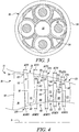
- the gas turbine engine shown in Figure 1 has a split flow nozzle 18, 20 meaning that the flow through the bypass duct 22 has its own nozzle 18 that is separate to and radially outside the core engine nozzle 20.
- this is not limiting, and any aspect of the present disclosure may also apply to engines in which the flow through the bypass duct 22 and the flow through the core 11 are mixed, or combined, before (or upstream of) a single nozzle, which may be referred to as a mixed flow nozzle.
- One or both nozzles may have a fixed or variable area.
- the described example relates to a turbofan engine, the disclosure may apply, for example, to any type of gas turbine engine, such as an open rotor (in which the fan stage is not surrounded by a nacelle) or turboprop engine, for example.
- the gas turbine engine 10 may not comprise a gearbox 30.
- Figure 4 illustrates a forward part of the low pressure compressor 14 in further detail.
- the third vanes V3 may have a leading edge span comprised between 70 mm and 120 mm and a true chord comprised between 15 mm and 45 mm. Blades and vanes are distanced by respective axial gaps, i.e. gaps along the principal rotational axis 9. The axial gaps may vary along the span of the blades.
- a first axial gap G1 is defined between the first blade B1 and the first vane V1
- a second axial gap G2 is defined between the first vane V1 and the second blade B2
- a third axial gap G3 is defined between the second blade B2 and the second vane V2
- a forth axial gap G4 is defined between the second vane V2 and the third blade B3
- a fifth axial gap G5 is defined between the third blade B3 and the third vane V3.
Claims (15)
- Moteur à turbine à gaz (10) comprenant :- une soufflante (23) montée pour tourner autour d'un axe longitudinal principal (9),- un noyau de moteur (11), comprenant en série dans le sens de l'écoulement axial un compresseur (14), une chambre de combustion (16) et une turbine (19) couplée au compresseur (14) par l'intermédiaire d'un arbre (26), ledit compresseur (14) étant un compresseur basse pression (support à la page 18, premier paragraphe de la demande telle que déposée) et- un réducteur (30) avec une entrée en provenance de l'arbre (26) et une sortie vers la soufflante (23), la soufflante (23) étant adaptée pour tourner à une vitesse de rotation inférieure à celle de l'arbre (26),ledit compresseur (14) comprenant un premier étage (ST1) avec un premier rotor (R1) et un premier stator (S1), un deuxième étage (ST2) avec un deuxième rotor (R2) et un deuxième stator (S2), et un troisième étage (ST3) avec un troisième rotor (R3) et un troisième stator (S3), le premier (ST1), le deuxième (ST2) et le troisième (ST3) étage du compresseur (14) étant les trois premiers étages du compresseur (support à la page 2, lignes 35-36), chaque rotor et stator comprenant une pluralité de pales (B1, B2, B3) et d'aubes (V1, V2, V3), respectivement, avec un bord d'attaque, un bord de fuite et une pointe, et des rotors et stators adjacents étant séparés par des espaces axiaux,
caractérisé en ce que, entre le premier rotor et le troisième rotor, les rotors et les stators sont agencés de sorte qu'une somme d'espaces axiaux à mi-envergure (AGMS1, AGMS2, AGMS3, AGMS4) entre le bord de fuite de pale (52) du premier rotor (R1) et le bord d'attaque d'aube (56) du premier stator (S1), le bord de fuite d'aube (58) du premier stator (V1) et le bord d'attaque de pale (62) du deuxième rotor (R2), le bord de fuite de pale (64) du deuxième rotor (R2) et le bord d'attaque d'aube (68) du deuxième stator (S2), et le bord de fuite d'aube (70) du deuxième stator (S2) et le bord d'attaque de pale (74) du troisième rotor (R1) est égal à

- Moteur à turbine à gaz selon la revendication 1, a étant inférieur à 115 mm.
- Moteur à turbine à gaz selon l'une quelconque des revendications précédentes, une somme des espaces axiaux de pointe (AGT1, AGT2, AGT3, AGT4) entre le bord de fuite de pale (52) du premier rotor (R1) et le bord d'attaque d'aube (56) du premier stator (S1), le bord de fuite d'aube (58) du premier stator (S1) et le bord d'attaque de pale (62) du deuxième rotor (R2), le bord de fuite de pale (64) du deuxième rotor (R2) et le bord d'attaque d'aube (68) du deuxième stator (S2), et le bord de fuite d'aube (70) du deuxième stator (S2) et le bord d'attaque de pale (74) du troisième rotor (R3) étant égale à

- Moteur à turbine à gaz selon l'une quelconque des revendications précédentes, une distance axiale à mi-envergure (AGMS 1) entre le bord de fuite de pale (52) du premier rotor (R1) et le bord d'attaque d'aube (56) du premier stator (S1) étant égale à

- Moteur à turbine à gaz selon l'une quelconque des revendications précédentes, une distance axiale de pointe (AGT1) entre le bord de fuite de pale (52) du premier rotor (R1) et le bord d'attaque d'aube (56) du premier stator (S1) étant égale à

- Moteur à turbine à gaz selon l'une quelconque des revendications précédentes, une distance axiale de pointe (AGT3) entre le bord de fuite de pale (64) du deuxième rotor (R2) et le bord d'attaque d'aube (68) du deuxième stator (S2) étant égale à

- Moteur à turbine à gaz selon l'une quelconque des revendications précédentes, une distance axiale à mi-envergure (AGMS5) entre le bord de fuite de pale (76) du troisième rotor (R3) et le bord d'attaque d'aube (80) du troisième stator (S3) étant égale à

- Moteur à turbine à gaz selon l'une quelconque des revendications précédentes, une distance axiale de pointe (AGT5) entre le bord de fuite de pale (76) du troisième rotor (R3) et le bord d'attaque d'aube (80) du troisième stator (S3) étant égale à

- Moteur à turbine à gaz selon l'une quelconque des revendications précédentes, une distance axiale à mi-envergure (AGMS2) entre le bord de fuite d'aube (58) du premier stator (S1) et le bord d'attaque de pale (62) du deuxième rotor (R2) étant égale à

- Moteur à turbine à gaz selon l'une quelconque des revendications précédentes, une distance axiale de pointe (AGT2) entre le bord de fuite d'aube (58) du premier stator (S1) et le bord d'attaque de pale (62) du deuxième rotor (R2) étant égale à

- Moteur à turbine à gaz selon l'une quelconque des revendications précédentes, une distance axiale à mi-envergure (AGMS4) entre le bord de fuite d'aube (70) du deuxième stator (S2) et le bord d'attaque de pale (74) du troisième rotor (R3) étant égal à

- Moteur à turbine à gaz selon l'une quelconque des revendications précédentes, une distance axiale de pointe (AGT4) entre le bord de fuite d'aube (70) du deuxième stator (S2) et le bord d'attaque de pale (74) du troisième rotor (R3) étant égale à

- Moteur à turbine à gaz selon l'une quelconque des revendications précédentes, ledit compresseur (14) comprenant de 3 à 8 étages.
- Moteur à turbine à gaz selon l'une quelconque des revendications précédentes, ladite turbine (19) étant une turbine basse pression, ledit arbre (26) étant un premier arbre, ledit moteur à turbine à gaz (10) comprenant en outre un compresseur haute pression en aval du compresseur basse pression, une turbine haute pression (17) en amont de la turbine basse pression, et un second arbre (27) couplant la turbine haute pression (17) au compresseur haute pression (15).
- Moteur à turbine à gaz selon l'une quelconque des revendications précédentes, ladite soufflante (23) possédant un diamètre supérieur à 230 cm et ladite fonction de débit d'entrée étant comprise entre 4 et 20 (kg/s·K0,5/kPa).
Priority Applications (1)
| Application Number | Priority Date | Filing Date | Title |
|---|---|---|---|
| EP21184444.4A EP3913192B1 (fr) | 2018-12-14 | 2019-11-14 | Moteur à turbine à gaz |
Applications Claiming Priority (1)
| Application Number | Priority Date | Filing Date | Title |
|---|---|---|---|
| GBGB1820400.8A GB201820400D0 (en) | 2018-12-14 | 2018-12-14 | Ice crystal protection for a gas turbine engine |
Related Child Applications (2)
| Application Number | Title | Priority Date | Filing Date |
|---|---|---|---|
| EP21184444.4A Division EP3913192B1 (fr) | 2018-12-14 | 2019-11-14 | Moteur à turbine à gaz |
| EP21184444.4A Division-Into EP3913192B1 (fr) | 2018-12-14 | 2019-11-14 | Moteur à turbine à gaz |
Publications (2)
| Publication Number | Publication Date |
|---|---|
| EP3667022A1 EP3667022A1 (fr) | 2020-06-17 |
| EP3667022B1 true EP3667022B1 (fr) | 2021-08-25 |
Family
ID=65147290
Family Applications (2)
| Application Number | Title | Priority Date | Filing Date |
|---|---|---|---|
| EP19209030.6A Active EP3667022B1 (fr) | 2018-12-14 | 2019-11-14 | Protection contre les cristaux de glace pour un turboréacteur |
| EP21184444.4A Active EP3913192B1 (fr) | 2018-12-14 | 2019-11-14 | Moteur à turbine à gaz |
Family Applications After (1)
| Application Number | Title | Priority Date | Filing Date |
|---|---|---|---|
| EP21184444.4A Active EP3913192B1 (fr) | 2018-12-14 | 2019-11-14 | Moteur à turbine à gaz |
Country Status (4)
| Country | Link |
|---|---|
| US (1) | US10578027B1 (fr) |
| EP (2) | EP3667022B1 (fr) |
| CN (1) | CN111322158A (fr) |
| GB (1) | GB201820400D0 (fr) |
Families Citing this family (2)
| Publication number | Priority date | Publication date | Assignee | Title |
|---|---|---|---|---|
| CN113323901B (zh) * | 2021-06-09 | 2023-04-07 | 奇鋐科技股份有限公司 | 串联风扇 |
| US11655757B2 (en) * | 2021-07-30 | 2023-05-23 | Rolls-Royce North American Technologies Inc. | Modular multistage compressor system for gas turbine engines |
Family Cites Families (10)
| Publication number | Priority date | Publication date | Assignee | Title |
|---|---|---|---|---|
| GB1197711A (en) * | 1964-12-02 | 1970-07-08 | Gen Electric | Improvements in Turbofan Type Engine. |
| US6725645B1 (en) * | 2002-10-03 | 2004-04-27 | General Electric Company | Turbofan engine internal anti-ice device |
| US7967571B2 (en) * | 2006-11-30 | 2011-06-28 | General Electric Company | Advanced booster rotor blade |
| US20120275922A1 (en) * | 2011-04-26 | 2012-11-01 | Praisner Thomas J | High area ratio turbine vane |
| ES2891562T3 (es) * | 2011-12-20 | 2022-01-28 | MTU Aero Engines AG | Turbomaquinaria y etapa de turbomaquinaria |
| EP3620617B1 (fr) * | 2014-12-15 | 2022-10-26 | Raytheon Technologies Corporation | Chauffage de carter de générateur de gaz pour moteurs à turbine à gaz |
| FR3034145B1 (fr) * | 2015-03-26 | 2017-04-07 | Snecma | Etage de compresseur |
| BE1023289B1 (fr) * | 2015-07-17 | 2017-01-24 | Safran Aero Boosters S.A. | Bec de separation de compresseur basse pression de turbomachine axiale avec conduit annulaire de degivrage |
| US10683805B2 (en) * | 2015-07-30 | 2020-06-16 | Safran Aircraft Engines | Anti-icing system for a turbine engine vane |
| BE1023531B1 (fr) * | 2015-10-15 | 2017-04-25 | Safran Aero Boosters S.A. | Dispositif degivrant de bec de separation de compresseur de turbomachine axiale |
-
2018
- 2018-12-14 GB GBGB1820400.8A patent/GB201820400D0/en not_active Ceased
-
2019
- 2019-05-14 US US16/411,312 patent/US10578027B1/en active Active
- 2019-11-14 EP EP19209030.6A patent/EP3667022B1/fr active Active
- 2019-11-14 EP EP21184444.4A patent/EP3913192B1/fr active Active
- 2019-11-28 CN CN201911190539.7A patent/CN111322158A/zh active Pending
Also Published As
| Publication number | Publication date |
|---|---|
| EP3667022A1 (fr) | 2020-06-17 |
| US10578027B1 (en) | 2020-03-03 |
| EP3913192A1 (fr) | 2021-11-24 |
| GB201820400D0 (en) | 2019-01-30 |
| EP3913192B1 (fr) | 2024-03-13 |
| CN111322158A (zh) | 2020-06-23 |
Similar Documents
| Publication | Publication Date | Title |
|---|---|---|
| EP3587749B1 (fr) | Moteur de turbine à gaz | |
| EP3708818A1 (fr) | Installation et fonctionnement efficaces d'un moteur à turbine à gaz | |
| US11619135B2 (en) | Super-cooled ice impact protection for a gas turbine engine | |
| EP3611398B1 (fr) | Système de palier de stabilisation pour moteurs à double flux à engrenage | |
| US11920499B2 (en) | Gas turbine engine with improved VIGV shielding | |
| EP3708850B1 (fr) | Agencement de conduit de flux primaire d'un moteur à turbine à gaz | |
| EP3708805A1 (fr) | Installation et fonctionnement efficaces d'un moteur à turbine à gaz | |
| EP3608509B1 (fr) | Moteur de turbine à gaz avec composants de turbine en composite à matrice céramique | |
| EP3667022B1 (fr) | Protection contre les cristaux de glace pour un turboréacteur | |
| US11732603B2 (en) | Ice crystal protection for a gas turbine engine | |
| EP3683431A1 (fr) | Conduit d'entrée hautement chargé dans un turboréacteur à engrenages | |
| EP3594447A1 (fr) | Aubes de redresseur de moteur de turbine à gaz | |
| EP3808963B1 (fr) | Moteur de turbine à gaz | |
| EP3594476B1 (fr) | Agencement de montage de moteur à turbine à gaz à turbosoufflante à engrenage | |
| EP3835563B1 (fr) | Système de contrôle environnemental | |
| EP3569840B1 (fr) | Moteur de turbine à gaz | |
| EP3741982A1 (fr) | Moteur de turbine à gaz | |
| EP3617557A1 (fr) | Système de distribution d'huile auxiliaire et moteur à turbine à gaz comportant un système de distribution d'huile auxiliaire |
Legal Events
| Date | Code | Title | Description |
|---|---|---|---|
| PUAI | Public reference made under article 153(3) epc to a published international application that has entered the european phase |
Free format text: ORIGINAL CODE: 0009012 |
|
| STAA | Information on the status of an ep patent application or granted ep patent |
Free format text: STATUS: THE APPLICATION HAS BEEN PUBLISHED |
|
| AK | Designated contracting states |
Kind code of ref document: A1 Designated state(s): AL AT BE BG CH CY CZ DE DK EE ES FI FR GB GR HR HU IE IS IT LI LT LU LV MC MK MT NL NO PL PT RO RS SE SI SK SM TR |
|
| AX | Request for extension of the european patent |
Extension state: BA ME |
|
| STAA | Information on the status of an ep patent application or granted ep patent |
Free format text: STATUS: REQUEST FOR EXAMINATION WAS MADE |
|
| 17P | Request for examination filed |
Effective date: 20201216 |
|
| RBV | Designated contracting states (corrected) |
Designated state(s): AL AT BE BG CH CY CZ DE DK EE ES FI FR GB GR HR HU IE IS IT LI LT LU LV MC MK MT NL NO PL PT RO RS SE SI SK SM TR |
|
| RIC1 | Information provided on ipc code assigned before grant |
Ipc: F01D 5/14 20060101ALN20210517BHEP Ipc: F04D 25/02 20060101ALI20210517BHEP Ipc: F04D 19/02 20060101ALI20210517BHEP Ipc: F01D 25/02 20060101ALI20210517BHEP Ipc: F01D 21/10 20060101ALI20210517BHEP Ipc: F01D 9/04 20060101AFI20210517BHEP |
|
| GRAP | Despatch of communication of intention to grant a patent |
Free format text: ORIGINAL CODE: EPIDOSNIGR1 |
|
| STAA | Information on the status of an ep patent application or granted ep patent |
Free format text: STATUS: GRANT OF PATENT IS INTENDED |
|
| GRAS | Grant fee paid |
Free format text: ORIGINAL CODE: EPIDOSNIGR3 |
|
| INTG | Intention to grant announced |
Effective date: 20210625 |
|
| GRAA | (expected) grant |
Free format text: ORIGINAL CODE: 0009210 |
|
| STAA | Information on the status of an ep patent application or granted ep patent |
Free format text: STATUS: THE PATENT HAS BEEN GRANTED |
|
| AK | Designated contracting states |
Kind code of ref document: B1 Designated state(s): AL AT BE BG CH CY CZ DE DK EE ES FI FR GB GR HR HU IE IS IT LI LT LU LV MC MK MT NL NO PL PT RO RS SE SI SK SM TR |
|
| REG | Reference to a national code |
Ref country code: CH Ref legal event code: EP |
|
| REG | Reference to a national code |
Ref country code: IE Ref legal event code: FG4D Ref country code: AT Ref legal event code: REF Ref document number: 1423991 Country of ref document: AT Kind code of ref document: T Effective date: 20210915 |
|
| REG | Reference to a national code |
Ref country code: DE Ref legal event code: R096 Ref document number: 602019007156 Country of ref document: DE |
|
| REG | Reference to a national code |
Ref country code: LT Ref legal event code: MG9D |
|
| REG | Reference to a national code |
Ref country code: NL Ref legal event code: MP Effective date: 20210825 |
|
| REG | Reference to a national code |
Ref country code: AT Ref legal event code: MK05 Ref document number: 1423991 Country of ref document: AT Kind code of ref document: T Effective date: 20210825 |
|
| PG25 | Lapsed in a contracting state [announced via postgrant information from national office to epo] |
Ref country code: ES Free format text: LAPSE BECAUSE OF FAILURE TO SUBMIT A TRANSLATION OF THE DESCRIPTION OR TO PAY THE FEE WITHIN THE PRESCRIBED TIME-LIMIT Effective date: 20210825 Ref country code: SE Free format text: LAPSE BECAUSE OF FAILURE TO SUBMIT A TRANSLATION OF THE DESCRIPTION OR TO PAY THE FEE WITHIN THE PRESCRIBED TIME-LIMIT Effective date: 20210825 Ref country code: RS Free format text: LAPSE BECAUSE OF FAILURE TO SUBMIT A TRANSLATION OF THE DESCRIPTION OR TO PAY THE FEE WITHIN THE PRESCRIBED TIME-LIMIT Effective date: 20210825 Ref country code: LT Free format text: LAPSE BECAUSE OF FAILURE TO SUBMIT A TRANSLATION OF THE DESCRIPTION OR TO PAY THE FEE WITHIN THE PRESCRIBED TIME-LIMIT Effective date: 20210825 Ref country code: AT Free format text: LAPSE BECAUSE OF FAILURE TO SUBMIT A TRANSLATION OF THE DESCRIPTION OR TO PAY THE FEE WITHIN THE PRESCRIBED TIME-LIMIT Effective date: 20210825 Ref country code: BG Free format text: LAPSE BECAUSE OF FAILURE TO SUBMIT A TRANSLATION OF THE DESCRIPTION OR TO PAY THE FEE WITHIN THE PRESCRIBED TIME-LIMIT Effective date: 20211125 Ref country code: PT Free format text: LAPSE BECAUSE OF FAILURE TO SUBMIT A TRANSLATION OF THE DESCRIPTION OR TO PAY THE FEE WITHIN THE PRESCRIBED TIME-LIMIT Effective date: 20211227 Ref country code: NO Free format text: LAPSE BECAUSE OF FAILURE TO SUBMIT A TRANSLATION OF THE DESCRIPTION OR TO PAY THE FEE WITHIN THE PRESCRIBED TIME-LIMIT Effective date: 20211125 Ref country code: HR Free format text: LAPSE BECAUSE OF FAILURE TO SUBMIT A TRANSLATION OF THE DESCRIPTION OR TO PAY THE FEE WITHIN THE PRESCRIBED TIME-LIMIT Effective date: 20210825 Ref country code: FI Free format text: LAPSE BECAUSE OF FAILURE TO SUBMIT A TRANSLATION OF THE DESCRIPTION OR TO PAY THE FEE WITHIN THE PRESCRIBED TIME-LIMIT Effective date: 20210825 |
|
| PG25 | Lapsed in a contracting state [announced via postgrant information from national office to epo] |
Ref country code: PL Free format text: LAPSE BECAUSE OF FAILURE TO SUBMIT A TRANSLATION OF THE DESCRIPTION OR TO PAY THE FEE WITHIN THE PRESCRIBED TIME-LIMIT Effective date: 20210825 Ref country code: LV Free format text: LAPSE BECAUSE OF FAILURE TO SUBMIT A TRANSLATION OF THE DESCRIPTION OR TO PAY THE FEE WITHIN THE PRESCRIBED TIME-LIMIT Effective date: 20210825 Ref country code: GR Free format text: LAPSE BECAUSE OF FAILURE TO SUBMIT A TRANSLATION OF THE DESCRIPTION OR TO PAY THE FEE WITHIN THE PRESCRIBED TIME-LIMIT Effective date: 20211126 |
|
| PG25 | Lapsed in a contracting state [announced via postgrant information from national office to epo] |
Ref country code: NL Free format text: LAPSE BECAUSE OF FAILURE TO SUBMIT A TRANSLATION OF THE DESCRIPTION OR TO PAY THE FEE WITHIN THE PRESCRIBED TIME-LIMIT Effective date: 20210825 |
|
| PG25 | Lapsed in a contracting state [announced via postgrant information from national office to epo] |
Ref country code: DK Free format text: LAPSE BECAUSE OF FAILURE TO SUBMIT A TRANSLATION OF THE DESCRIPTION OR TO PAY THE FEE WITHIN THE PRESCRIBED TIME-LIMIT Effective date: 20210825 |
|
| REG | Reference to a national code |
Ref country code: DE Ref legal event code: R097 Ref document number: 602019007156 Country of ref document: DE |
|
| PG25 | Lapsed in a contracting state [announced via postgrant information from national office to epo] |
Ref country code: SM Free format text: LAPSE BECAUSE OF FAILURE TO SUBMIT A TRANSLATION OF THE DESCRIPTION OR TO PAY THE FEE WITHIN THE PRESCRIBED TIME-LIMIT Effective date: 20210825 Ref country code: SK Free format text: LAPSE BECAUSE OF FAILURE TO SUBMIT A TRANSLATION OF THE DESCRIPTION OR TO PAY THE FEE WITHIN THE PRESCRIBED TIME-LIMIT Effective date: 20210825 Ref country code: RO Free format text: LAPSE BECAUSE OF FAILURE TO SUBMIT A TRANSLATION OF THE DESCRIPTION OR TO PAY THE FEE WITHIN THE PRESCRIBED TIME-LIMIT Effective date: 20210825 Ref country code: EE Free format text: LAPSE BECAUSE OF FAILURE TO SUBMIT A TRANSLATION OF THE DESCRIPTION OR TO PAY THE FEE WITHIN THE PRESCRIBED TIME-LIMIT Effective date: 20210825 Ref country code: CZ Free format text: LAPSE BECAUSE OF FAILURE TO SUBMIT A TRANSLATION OF THE DESCRIPTION OR TO PAY THE FEE WITHIN THE PRESCRIBED TIME-LIMIT Effective date: 20210825 Ref country code: AL Free format text: LAPSE BECAUSE OF FAILURE TO SUBMIT A TRANSLATION OF THE DESCRIPTION OR TO PAY THE FEE WITHIN THE PRESCRIBED TIME-LIMIT Effective date: 20210825 |
|
| PG25 | Lapsed in a contracting state [announced via postgrant information from national office to epo] |
Ref country code: MC Free format text: LAPSE BECAUSE OF FAILURE TO SUBMIT A TRANSLATION OF THE DESCRIPTION OR TO PAY THE FEE WITHIN THE PRESCRIBED TIME-LIMIT Effective date: 20210825 |
|
| PLBE | No opposition filed within time limit |
Free format text: ORIGINAL CODE: 0009261 |
|
| STAA | Information on the status of an ep patent application or granted ep patent |
Free format text: STATUS: NO OPPOSITION FILED WITHIN TIME LIMIT |
|
| PG25 | Lapsed in a contracting state [announced via postgrant information from national office to epo] |
Ref country code: LU Free format text: LAPSE BECAUSE OF NON-PAYMENT OF DUE FEES Effective date: 20211114 Ref country code: IT Free format text: LAPSE BECAUSE OF FAILURE TO SUBMIT A TRANSLATION OF THE DESCRIPTION OR TO PAY THE FEE WITHIN THE PRESCRIBED TIME-LIMIT Effective date: 20210825 Ref country code: BE Free format text: LAPSE BECAUSE OF NON-PAYMENT OF DUE FEES Effective date: 20211130 |
|
| REG | Reference to a national code |
Ref country code: BE Ref legal event code: MM Effective date: 20211130 |
|
| 26N | No opposition filed |
Effective date: 20220527 |
|
| PG25 | Lapsed in a contracting state [announced via postgrant information from national office to epo] |
Ref country code: SI Free format text: LAPSE BECAUSE OF FAILURE TO SUBMIT A TRANSLATION OF THE DESCRIPTION OR TO PAY THE FEE WITHIN THE PRESCRIBED TIME-LIMIT Effective date: 20210825 |
|
| PG25 | Lapsed in a contracting state [announced via postgrant information from national office to epo] |
Ref country code: IE Free format text: LAPSE BECAUSE OF NON-PAYMENT OF DUE FEES Effective date: 20211114 |
|
| PGFP | Annual fee paid to national office [announced via postgrant information from national office to epo] |
Ref country code: FR Payment date: 20221122 Year of fee payment: 4 |
|
| PG25 | Lapsed in a contracting state [announced via postgrant information from national office to epo] |
Ref country code: CY Free format text: LAPSE BECAUSE OF FAILURE TO SUBMIT A TRANSLATION OF THE DESCRIPTION OR TO PAY THE FEE WITHIN THE PRESCRIBED TIME-LIMIT Effective date: 20210825 |
|
| REG | Reference to a national code |
Ref country code: CH Ref legal event code: PL |
|
| P01 | Opt-out of the competence of the unified patent court (upc) registered |
Effective date: 20230528 |
|
| PG25 | Lapsed in a contracting state [announced via postgrant information from national office to epo] |
Ref country code: LI Free format text: LAPSE BECAUSE OF NON-PAYMENT OF DUE FEES Effective date: 20221130 Ref country code: HU Free format text: LAPSE BECAUSE OF FAILURE TO SUBMIT A TRANSLATION OF THE DESCRIPTION OR TO PAY THE FEE WITHIN THE PRESCRIBED TIME-LIMIT; INVALID AB INITIO Effective date: 20191114 Ref country code: CH Free format text: LAPSE BECAUSE OF NON-PAYMENT OF DUE FEES Effective date: 20221130 |
|
| PGFP | Annual fee paid to national office [announced via postgrant information from national office to epo] |
Ref country code: DE Payment date: 20231127 Year of fee payment: 5 |