EP3666967A1 - Method for inserting laundry items into feeding machine - Google Patents
Method for inserting laundry items into feeding machine Download PDFInfo
- Publication number
- EP3666967A1 EP3666967A1 EP19210768.8A EP19210768A EP3666967A1 EP 3666967 A1 EP3666967 A1 EP 3666967A1 EP 19210768 A EP19210768 A EP 19210768A EP 3666967 A1 EP3666967 A1 EP 3666967A1
- Authority
- EP
- European Patent Office
- Prior art keywords
- corner
- laundry
- bracket
- item
- items
- Prior art date
- Legal status (The legal status is an assumption and is not a legal conclusion. Google has not performed a legal analysis and makes no representation as to the accuracy of the status listed.)
- Granted
Links
- 238000000034 method Methods 0.000 title claims description 34
- 238000012937 correction Methods 0.000 claims abstract description 18
- 238000003384 imaging method Methods 0.000 claims description 17
- 230000000007 visual effect Effects 0.000 claims description 11
- 230000006735 deficit Effects 0.000 abstract 1
- 230000007547 defect Effects 0.000 description 6
- 238000012546 transfer Methods 0.000 description 5
- 238000011156 evaluation Methods 0.000 description 4
- 238000011179 visual inspection Methods 0.000 description 4
- 238000012545 processing Methods 0.000 description 2
- 230000032258 transport Effects 0.000 description 2
- 230000002411 adverse Effects 0.000 description 1
- 238000000151 deposition Methods 0.000 description 1
- 238000013461 design Methods 0.000 description 1
- 230000001771 impaired effect Effects 0.000 description 1
- 238000003780 insertion Methods 0.000 description 1
- 230000037431 insertion Effects 0.000 description 1
- 230000000630 rising effect Effects 0.000 description 1
- 238000000926 separation method Methods 0.000 description 1
Images


Classifications
-
- D—TEXTILES; PAPER
- D06—TREATMENT OF TEXTILES OR THE LIKE; LAUNDERING; FLEXIBLE MATERIALS NOT OTHERWISE PROVIDED FOR
- D06F—LAUNDERING, DRYING, IRONING, PRESSING OR FOLDING TEXTILE ARTICLES
- D06F67/00—Details of ironing machines provided for in groups D06F61/00, D06F63/00, or D06F65/00
- D06F67/04—Arrangements for feeding or spreading the linen
-
- D—TEXTILES; PAPER
- D06—TREATMENT OF TEXTILES OR THE LIKE; LAUNDERING; FLEXIBLE MATERIALS NOT OTHERWISE PROVIDED FOR
- D06F—LAUNDERING, DRYING, IRONING, PRESSING OR FOLDING TEXTILE ARTICLES
- D06F95/00—Laundry systems or arrangements of apparatus or machines; Mobile laundries
Definitions
- the invention relates to a method for entering and / or feeding items of laundry into an input machine according to the preamble of claim 1.
- Items of laundry in particular flat items of laundry, such as tablecloths, serviettes, sheets, duvet covers and pillowcases, are spread out or stretched out by so-called input machines and thus fed to a subsequent laundry treatment device, in particular a defect.
- a respective item of laundry with adjacent corners of a front edge seen in the feed direction is entered in brackets of the input machine.
- brackets can be spreading brackets of a spreading device of the input machine or loading clips of the input machine.
- the invention has for its object to provide a method for entering or feeding items of laundry into an input machine that, despite at least partial automation, meets all quality requirements.
- a method for solving this problem has the measures of claim 1.
- this method it is provided that the at least one corner of at least those items of laundry to which high quality requirements are made is checked manually and, if necessary, corrected if necessary. As a result, checks and, if necessary, corrections are only required for items of laundry with high quality requirements, but not for items of clothing to which no special quality requirements are imposed.
- the intended, preferably ideal, position of the corner in the clip holding it is only checked or checked for selected items of laundry.
- selected items of laundry are checked or monitored with regard to the correct fit of the corner which is automatically entered into a bracket and to which high quality demands are made, particularly with regard to the quality of the defect. It is therefore only necessary to check or check that the corner is correctly seated in the bracket for items of laundry that have to meet higher quality standards. Control of the correct fit of at least one corner in the clip assigned to it can thus be omitted for items of laundry to which no particularly high quality demands are made.
- the position is manually determined only when the position of the corner of the item of laundry automatically entered into the clamp is detected or deviations too large from the predetermined or ideal position of the corner in the clamp correct this corner in parentheses. If, for example, the correct position of the corner in the bracket is visually checked by at least one imaging device and it is determined that a correction is not required, the check can also be carried out automatically without the need for a manual correction. In this case, manual intervention can be omitted, as a result of which the method according to the invention can be carried out quickly and economically.
- the visual check of the position of the corner of the respective item of laundry in a bracket holding this and any necessary correction of the position can either be carried out directly in front of the input machine, namely before the relevant corner is then preferably manually input to a clip of the input machine, or in the course of a Conveyor system that transports the respective item of laundry to the input machine and from which, if necessary, the automatic transfer of the item of laundry to the input machine or input of the item of laundry into the input machine.
- Another advantageous embodiment of the method provides that the manual or automatic visual control and / or any manual correction of the position of the corner of the item of laundry in the clip holding it is carried out by at least one operator.
- This operator can carry out the visual inspection without having to perform strenuous physical movements. If it is determined in certain cases that the corner has not been automatically hooked or inserted into the clamp provided for this purpose in the correct, in particular ideal position, the operator must act manually in order to correct the position.
- the devices shown in the figures exemplify various exemplary embodiments of the method according to the invention. But the procedure can be not only perform with the devices shown, it is rather generally suitable for any type of device for the automatic or partially automatic feeding and / or input of laundry items in input machines for spreading and feeding the laundry items to a defect or other laundry treatment device.
- the laundry items 10 are preferably so-called flat laundry items. These are mainly tablecloths, serviettes, duvet covers, pillow cases and bed sheets.
- Different devices shown for performing the method according to the invention have at least one input machine 11, to which the laundry items 10 can be fed and into which the laundry items 10 with adjacent corners 12, 13 of a front edge 14 can be entered.
- These measures are composed of feeding the laundry items 10 to the input machine 11 and manually and / or automatically entering adjacent corners 12, 13 of a front edge 14 of the respective laundry item 10 in loading clips or spreading clips of a spreading device of the input machine 11.
- the exemplary embodiments shown relate to the two-lane input of laundry items 10 into the input machine 11. That is, laundry items 10 are input into the input machine 11 along two parallel lanes, which are preferably of identical design. However, the invention is not restricted to this. Rather, the method according to the invention is also suitable for only one-lane or more than two-lane input of laundry items 10 into the input machine 11.
- two parallel, identical conveyor systems 16 and two in front of the input machine 11 are preferred same separator 17 provided.
- the respective separator 17 is used for targeted automatic picking out, preferably of an individual item of laundry 10 from a pile of laundry 18.
- the automatic picking out of the item 10 of laundry from the pile of laundry is controlled by an imaging device by means of a gripper 19 that can be moved up and down along a rising path 20.
- the gripper 19 passes on what he seizes, preferably individual items of laundry 10 to a subsequent supply device 21 of the separator 17.
- the supply device 21 optionally carries out a separation of several items of laundry 10 gripped simultaneously by the gripper 19 and holds the individual items of laundry 10 at a first corner 12 of the items of laundry ready to be taken over by the conveyor system 16 the item of laundry 10 hangs down freely from the first corner 12 held by the provision device 21 of the separator 17.
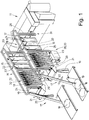
- the devices of the 1 to 5 differ in terms of their conveyor systems 16.
- the conveyor system 16 shown has a circumferential, endless conveyor path 22 along which the same clamps 23 can be moved.
- the brackets 23 are grouped in pairs. As a result, each item of laundry 10 hangs from a pair of clips 23 in front of the input machine, one clip 23 holding the first corner 12 and the subsequent second clip 23 holding the second adjacent corner 13 of the edge 14 of the respective item 10 of laundry.
- a strand of the conveyor section 22 which transports the clamps 23 with the laundry items 10 attached to them in the feed direction 15 is provided with three loops 24, 25, 26 which follow one another in the feed direction 15.
- the loops have a U-shaped route section lying in a vertical plane parallel to the feed direction 15 with a lower semicircular deflection arch.
- the loop 24 following the separator 17 forms a takeover point 27 for a first corner 12 of the laundry 10 from the separator 17 in the region of its lower deflection curve.
- the transfer takes place automatically by the first corner 12 of the conveyor system 17 being placed in the first bracket 23 of the pair of clips Items of laundry 10, for example from the separator 17, is suspended.
- the loop 25 following the loop 24 at a distance in the feed direction 15 is located in the area of a manual work station 28.
- This work station 28 is staffed by an operator 29.
- a loading station 30 at which the operator 29 manually hooks the second corner 13 adjacent to the first corner 12 already held in a bracket 23 into the subsequent second bracket 23 of the pair of clips.
- the respective item of laundry 10 then leaves the loading station 30 with the corners 12 and 13 of the edge 14 suspended in the successive clamps 23 of the respective pair of clamps.
- the loop 26 following the loop 25 in the feed direction 15 is arranged at an input point 31 of the input machine 11.
- the corner 12 and then the adjacent corner 13 of the edge 14 of the item 10 of laundry are automatically entered one after the other into loading clips (not shown) or directly into spreading clips (also not shown) of the input machine 11.
- the empty clamps 23 of the respective clamp pair are then transported back to a second branch of the conveyor line 22 of the conveyor system 16 to the first loop 24 behind the separator 17. These clamps 23 are then ready for the automatic takeover of the next item of laundry 10 from the separator 17.
- the conveyor system 16 has a storage path 32 and 33 both between the first loop 24 and the second loop 25, ie in front of the work station 28, and between the second loop 25 and the third loop 26 behind the work station 28.
- a storage path 32 and 33 both between the first loop 24 and the second loop 25, ie in front of the work station 28, and between the second loop 25 and the third loop 26 behind the work station 28.
- several hanging laundry items 10 can each be buffered until they are called up at the work station 28 or are automatically entered into the input machine 11.
- a first exemplary embodiment of the method according to the invention is described below using the device of Fig. 1 and 2nd explains: At the takeover point 27 of the loop 24 behind the singler 17, a first corner 12 of the laundry item 10 is automatically transferred to a first clip 23 of the clip pair in the respective conveyor system 16.
- the operator 29 visually checks the position of the at least one corner 12 of the item 10 of laundry which has previously been automatically entered into the bracket 23. This visual inspection can be carried out for all laundry items 10, but also only for selected laundry items 10, namely those to which increased quality requirements are made. Then other items of laundry 10, to which no higher quality requirements are imposed, need not be visually checked by the operator 29 in the area of the work station 28.
- the visual inspection of the corner 12 of the laundry item 10 automatically entered into the brackets 23 can alternatively also be carried out by at least one imaging device, for example, a camera.
- This at least one imaging device detects the seat of the corner 12 in the bracket 23 at the work station 28.
- An image evaluation device determines whether the corner 12 is correctly seated in the bracket 23 or not.
- a correction is made. This correction is made manually by the operator 29 by changing the position of the corner 12 in the bracket 23 such that the corner 12 receives or assumes its intended position in the bracket 23.
- the visual check can be carried out to determine whether the corner 12 is inserted sufficiently deep into a clip mouth of the clip 23, the section of the edge 14 in the clip 23 extending from the corner 12 runs horizontally or at least approximately horizontally and / or whether an outermost point of one Zipfels 34, in particular a corner point 35, at the point where the edge 14 and the transverse edge 36 of the laundry item meet, is on an outer edge 37 of the bracket 23 or close to the edge 37 outside the bracket 23.
- it can alternatively or additionally be provided that it is also checked whether the corner 12 is wrinkle-free in the bracket 23.
- a lower part of the clamp 23 holding the corner 12 is shown schematically, the corner 12 of the laundry item 10 having been automatically entered in the clamp mouth of the clamp 23.
- the corner 12 of the laundry item 10 clamped in the clamp 23 is checked visually at the work station 28, specifically by the operator 29 or an imaging device, and if necessary a manual correction is carried out by the operator 29.
- the ideal position 38 of the corner 12 in the bracket 23 is shown by a thick dot-dash line.
- a tolerance limit 39 is symbolized by a thin dot-dash line.
- the areas between the ideal position 38 and the tolerance limit 39 therefore represent tolerance ranges.
- the corner 12 protrudes the corner 12 with its tip 34 and especially the corner point 35 clearly opposite the outer edge 37 of the bracket 23.
- the corner 12 is not inserted sufficiently deep into the clamp mouth of the clamp 23.
- the dashed line represents the lowest point 41 of the clamp mouth of the clamp 23 after checking the position or the seat of the corner 12 of the laundry 10 in the bracket 23, the operator 29 must manually adjust the corner 12 in the bracket 23 at the work station 28. This is done in such a way that the outermost section of the edge 14 located in the bracket 23 is aligned approximately horizontally, in such a way that it lies in the horizontal tolerance range 40 between the dashed lines.
- the corner 12 of the laundry 10 is pulled further into the bracket 23 (based on the representation of the Fig. 6 to the right) and the corner 12 drawn so smoothly that no corner 34 is formed anymore and the corner point 35 and the side edge 36 of the item of laundry 10 running downward therefrom are within the tolerance range 40 lying between the two dashed vertical lines.
- the Fig. 3 shows a device that differs from that according to the Fig. 1 and 2nd differs only in that the conveyor system 16 has two parallel conveyor lines 42, 43 between each work station and each input point 31 of the input machine 11.
- the conveyor section 42 corresponds to the conveyor section 22 of the embodiment of FIG Fig. 1 and 2nd .
- the same reference numbers are therefore used for the same parts.
- the second conveyor line 43 next to the conveyor line 42 extends only from the work station 28 to the respective loading station 30 or input point 31 of the input machine 11. Accordingly, the second conveyor line 43 has only two loops 44 and 45, the loop 44 being located at the work station 28 is located and the loop 45 at the input point 31.
- Each conveyor section 42 and 43 has its own brackets 46, 47, which are identical to one another, the brackets 46, 47 being assigned to the different conveyor sections 42, 43.
- the clamps 46 of the conveyor line 42 are automatically loaded at the takeover point 27 behind the separator 17 with the first corner 12 of a respective item of laundry 10.
- a piece of laundry 10 hanging with the corner 12 on a bracket 46 is clamped by the operator 29 with the adjacent second corner 13 of the edge 14 into an empty bracket 47 of the second conveyor line 43 held ready.
- the respective laundry item 10 is then transported from the work station 28 to the input machine 11 with the state hanging at adjacent corners 12, 13 of the edge 14 in brackets 46, 47 of the two parallel conveyor lines 42, 43.
- the laundry items 10 are not transported along the conveyor path 42, 43 to the input machine 11, but rather transversely to the feed direction 15.
- the respective laundry item 10 with adjacent corners 12, 13 is simultaneously fed to the input machine 11, namely to the loading clips or directly to the spreading clips of the input machine 11, specifically preferably flying while the clamps 46 and 47 are moving past the rear loops 44 and 45 on the loading clamps or spreading clamps of the input machine 11 provided.
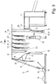
- each of the two parallel input strands of the laundry 10 in the common input machine 11 has a corner station 48.
- the corner station 48 is arranged between the respective singler 17 and the associated conveyor system 16.
- the corner station 48 has two successive pairs of belt conveyors 49, 50, each with two belt conveyors arranged one above the other.
- An initial region of a lower belt conveyor of the first, preferably horizontal, belt conveyor pair 49 protrudes from the lower belt conveyor to form a depositing point 51.
- the following belt conveyor pair 50 in the exemplary embodiment shown increases in the feed direction 15.
- the pairs of two interacting rollers 52 provided on each side of the rear pair of belt conveyors 50 form a corner catching device 53 for determining both opposite corners 12, 13 of the Edges 14 of the laundry item 10.
- the corners 12, 13 determined by the corner catching devices 53 are automatically transferred in succession from the corner station 48 into the successive brackets 23 in the lower deflection area of the loop 24 of the conveyor section 22.
- the loop 25 of the conveyor line located in the region of the work station 28 is reached 22 both corners 12, 13 of the item of laundry 10, already automatically bracketed in brackets 23.
- the operator 29 only needs to work at the work station 28 of the same if he has a piece of laundry 10 in front of him, to which particularly high quality requirements are made.
- This item of laundry 10 is then visually checked by the operator 29 or alternatively at least one imaging device with an image evaluation. If it is determined that one or both of the corners 12, 13 automatically entered in the successive brackets 23 have not been correctly entered automatically in the relevant bracket 23, for example the corners 12 and / or 13, in particular the edges 14 and 36 and the Corner point 35, outside the tolerance ranges 40, is corrected. This is done manually by the operator 29.
- the work station 28 is not provided on a central loop 25, but on the last loop 26 directly in front of the input machine 11.
- the central loop 24 according to FIG Fig. 4 can then be omitted.
- the operator checks the correct fit of the corners 12 and 13 entered in the bracket 23 and corrects them if necessary.
- the visual control can also be provided here by an imaging device and an image processing assigned to it. Immediately after the visual control and, if necessary, correction of the position of the corners 12, 13 has taken place, these are automatically matched to those in FIG Fig. 4 Transfer not shown loading clips or spreading clips of the input machine 11, in the embodiment of the Fig. 4 successively.
- the device of the Fig. 3 be modified by the work station 28 being arranged in the area of the loops 25, 44 directly in front of the input machine 11. Then, here too, directly before the corners 12 and 13 of the item of laundry 10 are entered into the loading clips or spreading clips of the input machine 11, the input position of the corners 12, 13 in the clips 46, 47 holding them and, if necessary, a manual correction of the position is checked the operator.
- the device of the embodiment of the Fig. 5 differs from that of Fig. 1 and 2nd only in that the conveyor section 54 has no middle loop 25.
- a work station 55 is then located directly in front of the input machine 11.
- the work station 55 is then also located at the lower deflection of the loop 26 which forms the input point 31 of the laundry item 10 into the input machine 11.
- the input point 31 and the work station 55 fall together.
- the operator 29 at the work station 55 visually checks those items of laundry 10 in which it is desired whether the first corner 12 has been automatically correctly entered into the bracket 23, that is to say the corner 12 is held on the bracket 23 within the tolerance ranges 40.
- a visual check can be carried out by at least one imaging device, preferably at least one camera and an image evaluation assigned to it.
- the operator 29 makes a corresponding correction manually.
- the position of the corner 12 of the laundry 10 in the bracket 23 is changed so that the edges 14 and 36 of the laundry 10 within the tolerance ranges 40 ( Fig. 6 ) lie.
- the bracket 23 automatically transfers the corner 12 one of the in the Fig. 5 Loading clamps, not shown, or immediately to a spreading clamp of the spreading device of the input machine 11.
- the second corner 13 of the edge 14 of the laundry 10 is in the embodiment of the Fig. 5 manually entered by the operator 29 into a loading bracket or an expanding bracket of the input machine 11. This is preferably done before the automatic entry of the corner 12 into the loading or spreading clamp of the input machine 11. It is also conceivable that the second corner 13 of the item of laundry 10 is manually entered into the loading or spreading clamp of the input machine 11 after the first Corner 12 of the laundry item 10 has been automatically transferred from the clamp 23 to the loading or spreading clamp of the input machine 11.
Landscapes
- Engineering & Computer Science (AREA)
- Textile Engineering (AREA)
- Treatment Of Fiber Materials (AREA)
- Sewing Machines And Sewing (AREA)
- Accessory Of Washing/Drying Machine, Commercial Washing/Drying Machine, Other Washing/Drying Machine (AREA)
Abstract
Beim Eingeben von Wäschestücken (10) in eine Eingabemaschine (11) wird mindestens eine Ecke (12) eines Randes (14) des betreffenden Wäschestücks (11) automatisch in eine diese Ecke (12) haltende Klammer (23) eingehängt. Es kommt vor, dass die Ecke (12) nicht ordnungsgemäß in die betreffende Klammer (23) automatisch eingegeben wird. Das führt zu einer Beeinträchtigung der Mangelqualität.Die Erfindung sieht es vor, durch eine Bedienungsperson (29) zu prüfen, ob die betreffende Ecke (12) ordnungsgemäß in die Klammer (23) eingegeben worden ist und erforderlichenfalls eine Korrektur durch die Bedienungsperson (29) vorzunehmen. Dadurch werden Beeinträchtigungen der Mangelqualität des Wäschestücks (10) zuverlässig vermieden.When laundry items (10) are entered into an input machine (11), at least one corner (12) of an edge (14) of the laundry item (11) in question is automatically hung in a bracket (23) holding this corner (12). It happens that the corner (12) is not automatically correctly entered into the relevant bracket (23). The invention provides for an operator (29) to check whether the relevant corner (12) has been correctly inserted into the bracket (23) and, if necessary, a correction by the operator (29). to make. Impairment of the lack quality of the item of laundry (10) is thereby reliably avoided.
Description
Die Erfindung betrifft ein Verfahren zum Eingeben und/oder Zuführen von Wäschestücken in eine Eingabemaschine gemäß dem Oberbegriff des Anspruchs 1.The invention relates to a method for entering and / or feeding items of laundry into an input machine according to the preamble of claim 1.
Wäschestücke, und zwar vor allem Flachwäschestücke, wie Tischdecken, Servietten, Bettlaken, Bettbezüge und Kopfkissenbezüge, werden von sogenannten Eingabemaschinen ausgebreitet bzw. ausgestreckt und so einer nachfolgenden Wäschebehandlungseinrichtung, insbesondere einer Mangel, zugeführt. Dazu wird ein jeweiliges Wäschestück mit benachbarten Ecken eines in Zuführrichtung gesehen vorderen Rands in Klammern der Eingabemaschine eingegeben. Bei diesen Klammern kann es sich um Spreizklammern einer Spreizeinrichtung der Eingabemaschine oder Beladeklammern der Eingabemaschine handeln.Items of laundry, in particular flat items of laundry, such as tablecloths, serviettes, sheets, duvet covers and pillowcases, are spread out or stretched out by so-called input machines and thus fed to a subsequent laundry treatment device, in particular a defect. For this purpose, a respective item of laundry with adjacent corners of a front edge seen in the feed direction is entered in brackets of the input machine. These brackets can be spreading brackets of a spreading device of the input machine or loading clips of the input machine.
Es ist aus Rationaliserungsgründen bekannt, die Eingabe von Wäschestücken in eine Eingabemaschine ganz oder zumindest teilweise zu automatisieren. Bei der teilweisen Automatisierung wird nur eine der benachbarten Ecken des von der Eingabemaschine auszustreckenden Rands des jeweiligen Wäschestücks automatisch in eine Klammer eingegeben. Die Eingabe der benachbarten zweiten Ecke erfolgt dann noch manuell. Bei der vollautomatischen Eingabe werden beide benachbarten Ecken des Rands automatisch in dafür vorgesehene Klammern eingegeben.For reasons of rationalization, it is known to fully or at least partially automate the input of laundry into an input machine. In the partial automation, only one of the adjacent corners of the edge of the respective item of laundry to be stretched out by the input machine is automatically entered into a bracket. The neighboring second corner is then entered manually. With the fully automatic entry, both adjacent corners of the edge are automatically entered in the brackets provided.
Bei Wäschestücken, an die hohe Qualitätsanforderungen, insbesondere hinsichtlich der Mangelqualität, gestellt werden, kann die automatische Eingabe auch nur einer der benachbarten Ecken des von der Eingabemaschine auszustreckenden Rands dazu führen, dass die Mangelqualität oder die Qualität einer sonstigen Behandlung der Wäschestücke beeinträchtigt wird, wenn diese Ecke nicht in idealer bzw. vorgesehener Weise automatisch in die jeweilige Klammer eingegeben worden ist. Das wird bei Wäschestücken, an die geringe Qualitätsanforderungen gestellt werden, akzeptiert; aber nicht bei Wäschestücken mit hohen Qualitätsanforderungen, vor allem Tischwäsche und/oder Hotelwäsche. Deswegen wird in der Praxis häufig so vorgegangen, dass nur Wäschestücke mit geringeren Qualitätsanforderungen teil- oder vollautomatisch der Eingabemaschine zugeführt bzw. in Eingabemaschinen eingegeben werden. Hingegen werden Wäschestücke, die hohe Qualitätsanforderungen erfüllen müssen, immer noch manuell in Eingabemaschinen eingegeben. Das ist zeit- und personalaufwendig. Darüber hinaus müssen die Wäschereien so ausgestattet sein, dass sie in der Lage sind, sowohl voll- oder teilautomatisch als auch rein manuell Wäschestücke in Eingabemaschinen einzugeben.In the case of items of laundry which are subject to high quality requirements, in particular with regard to the quality of the defect, the automatic input of even one of the adjacent corners of the edge to be stretched out by the input machine can result in the defect quality or the quality of any other treatment of the items of laundry being impaired if this corner was not automatically entered into the respective brackets in an ideal or intended manner. This is accepted for items of laundry with low quality requirements; but not for laundry items with high quality requirements, especially table linen and / or hotel linen. For this reason, in practice it is often carried out in such a way that only items of laundry with lower quality requirements are fed partially or fully automatically to the input machine or are input into input machines. In contrast, items of laundry that have to meet high quality requirements are still manually entered into input machines. This is time and personnel consuming. In addition, the laundries must be equipped in such a way that they are able to enter items of laundry into the input machine both fully or partially automatically and purely manually.
Der Erfindung liegt die Aufgabe zugrunde, ein Verfahren zum Eingeben bzw. Zuführen von Wäschestücken in eine Eingabemaschine zu schaffen, das trotz einer mindestens teilweisen Automatisierung allen Qualitätsanforderungen gerecht wird.The invention has for its object to provide a method for entering or feeding items of laundry into an input machine that, despite at least partial automation, meets all quality requirements.
Ein Verfahren zur Lösung dieser Aufgabe weist die Maßnahmen des Anspruchs 1 auf. Bei diesem Verfahren ist es vorgesehen, die manuell mindestens eine automatisch in eine Klammer eingegebene Ecke wenigstens solcher Wäschestücke, an die hohe Qualitätsanforderungen gestellt werden, zu kontrollieren und vorzugsweise erforderlichenfalls zu korrigieren. Dadurch sind Kontrollen und gegebenenfalls Korrekturen nur bei Wäschestücken mit hohen Qualitätsanforderungen erforderlich, nicht aber bei Wäschestücken, an die keine besonderen Qualitätsanforderungen gestellt werden.A method for solving this problem has the measures of claim 1. In this method, it is provided that the at least one corner of at least those items of laundry to which high quality requirements are made is checked manually and, if necessary, corrected if necessary. As a result, checks and, if necessary, corrections are only required for items of laundry with high quality requirements, but not for items of clothing to which no special quality requirements are imposed.
Bei qualitativ hochwertigen Wäschestücken ist vielfach nur eine Kontrolle erforderlich, weil eine zusätzliche Korrektur nur bei solchen Wäschestücken erforderlich ist, bei denen die manuelle bzw. visuelle Kontrolle ergeben hat, dass sie nicht automatisch wie vorgesehen, insbesondere idealerweise, in die betreffende Kammer eingegeben worden sind. Dadurch beschränken sich der visuelle Kontroll- und der gegebenenfalls erforderliche Korrekturaufwand beim erfindungsgemäßen Verfahren auf ein Minimum. Vor allem können Wäschestücke unabhängig von den Qualitätsansprüchen von der gleichen Vorrichtung in eine Eingabemaschine eingegeben und/oder dieser zugeführt werden.In the case of high-quality items of laundry, only one check is often necessary, because an additional correction is only required for items of laundry in which the manual or visual check has shown that they have not been automatically entered into the relevant chamber as intended, in particular ideally . As a result, the visual control effort and any necessary correction effort in the method according to the invention are kept to a minimum. Above all, items of laundry can be entered and / or fed into an input machine by the same device, regardless of the quality requirements.
Bevorzugt ist es vorgesehen, visuell zu kontrollieren, ob gegebenenfalls und in welchem Maße die Position der betreffenden automatisch in die Klammer eingegebenen Ecke von einer optimalen, insbesondere idealen, Position der Ecke in der Klammer abweicht. Es wird so kontrolliert, ob die betreffende Ecke ausreichend genau automatisch in die Klammer eingesetzt wurde oder festgestellt, ob eine Korrektur erforderlich ist. Die Kontrolle erfolgt dann vorzugsweise manuell.It is preferably provided to visually check whether and to what extent the position of the relevant corner automatically entered in the bracket deviates from an optimal, in particular ideal, position of the corner in the bracket. In this way, it is checked whether the corner in question has been automatically inserted into the bracket with sufficient accuracy or whether it needs to be corrected. The control is then preferably carried out manually.
Es ist denkbar, die Kontrolle automatisch mit mindestens einer bildgebenden Einrichtung durchzuführen, die die ermittelte Position der Ecke in der Klammer feststellt und vorzugsweise mit der idealen Position, insbesondere in einem Soll-Positionsbereich, vergleicht. Wenn dabei Vorgaben überschreitende Abweichungen von einer der mindestens einen bildgebenden Einrichtung zugeordneten Bildbearbeitung festgestellt werden, wird ein Signal erzeugt, so dass dann nur noch manuell die automatisch festgestellte, über den vorgegebenen Toleranzbereich hinausgehende Abweichung korrigiert werden muss. Die Kontrolle kann aber auch - wie eine eventuelle Korrektur - manuell erfolgen.It is conceivable to carry out the check automatically with at least one imaging device which determines the determined position of the corner in the bracket and preferably compares it with the ideal position, in particular in a target position range. If deviations exceeding specifications are determined by an image processing assigned to the at least one imaging device, a signal is generated, so that the automatically ascertained deviation that goes beyond the predetermined tolerance range then only has to be corrected manually. The check can also be done manually, like a possible correction.
Es kann manuell oder durch eine bildgebende Einrichtung visuell überprüft werden, ob die Ecke vollständig, vorzugsweise ausreichend tief, in ein Klammermaul der die Ecke haltende Klammer eingegeben worden ist. Dadurch werden nicht nur qualitätsbeeinflussende, unzulängliche automatische Eingaben der Ecke in die Klammer ermittelt, sondern auch die Gefahr des Herausrutschens einer unzureichend tief in die Klammer eingegebene Ecke des Wäschestücks reduziert, was die Betriebssicherheit des Verfahrens verbessert.It can be checked manually or by means of an imaging device whether the corner has been inserted completely, preferably sufficiently deep, into a clamp mouth of the clamp holding the corner. This not only determines inadequate automatic input of the corner into the bracket which influences quality, but also reduces the risk of a corner of the item of laundry being inserted insufficiently deep into the bracket, which improves the operational reliability of the method.
Es ist alternativ oder auch zusätzlich denkbar, zu überprüfen, wie weit nach der automatischen Eingabe der Ecke in die diese Ecke haltende Klammer ein Eckpunkt der Ecke, wo sich zwei an der Ecke zusammenlaufende Ränder des Wäschestücks treffen, von einer äußeren Kante der Klammer entfernt ist. Auch dies kann sowohl manuell als auch durch mindestens eine bildgebende Einrichtung visuell erfolgen. Wird festgestellt, dass der Eckpunkt zu weit von der äußeren Kante der Klammer entfernt ist, wird manuell die Position der Ecke in der Klammer korrigiert, und zwar so, dass der Eckpunkt sich ausreichend dicht an der äußeren Kante, vorzugsweise an der äußeren Kante, der Klammer befindet.It is alternatively or additionally conceivable to check how far after the automatic input of the corner into the bracket holding this corner, a corner point of the corner, where two edges of the item of laundry converge at the corner, is from an outer edge of the clip . This can also be done both manually and visually by at least one imaging device. If it is found that the corner point is too far from the outer edge of the bracket, the position of the corner in the bracket is manually corrected, in such a way that the corner point is sufficiently close to the outer edge, preferably to the outer edge, of the Bracket is located.
Es ist alternativ oder zusätzlich auch vorgesehen, zu überprüfen, ob der vom Eckpunkt der Ecke ausgehende äußere Randbereich des Randes zwischen den in den Klammern der Eingabemaschine einzugebenden benachbarten Ecken des Wäschestücks in der vorgesehenen, vorzugsweise horizontalen, Ausrichtung automatisch in die Klammer eingegeben worden ist. Dadurch wird sichergestellt, dass nach dem von der Spreizeinrichtung der Eingabemaschine erfolgenden Ausstreckung des vorderen Rands des Wäschestücks die an den benachbarten Ecken angrenzenden Randbereiche des vorderen Rands in Richtung des gestreckten vorderen Rands verlaufen und relativ zu dieser Richtung abgeknickt sind, was vor allem die Mangelqualität des Wäschestücks nachteilig beeinflussen würde.As an alternative or in addition, it is also provided to check whether the outer edge region of the edge starting from the corner point of the corner lies between the brackets in the parentheses the corner of the laundry item to be entered into the input machine has been automatically entered into the bracket in the intended, preferably horizontal, orientation. This ensures that after the front edge of the item of laundry has been extended by the spreading device of the input machine, the edge regions of the front edge adjacent to the adjacent corners run in the direction of the stretched front edge and are kinked relative to this direction, which primarily affects the lack quality of the Laundry items would adversely affect.
Mit einer vorteilhaften Ausgestaltung des Verfahrens wird die vorgesehene, vorzugsweise ideale Position der Ecke in der sie haltenden Klammer nur bei ausgewählten Wäschestücken überprüft bzw. kontrolliert. Bevorzugt werden nur solche Wäschestücke hinsichtlich des korrekten Sitzes der automatisch in eine Klammer eingegebenen Ecke geprüft bzw. überwacht, an die hohe Qualitätsansprüche, vor allem hinsichtlich der Mangelqualität, gestellt werden. Es braucht so die Kontrolle bzw. Überprüfung des richtigen Sitzes der Ecke in der Klammer nur bei solchen Wäschestücken zu erfolgen, die höheren Qualitätsansprüchen genügen müssen. Es kann somit die Kontrolle des richtigen Sitzes mindestens einer Ecke in der ihr zugeordneten Klammer bei solchen Wäschestücken unterbleiben, an die keine besonders hohen Qualitätsansprüche gestellt werden.With an advantageous embodiment of the method, the intended, preferably ideal, position of the corner in the clip holding it is only checked or checked for selected items of laundry. Preferably, only those items of laundry are checked or monitored with regard to the correct fit of the corner which is automatically entered into a bracket and to which high quality demands are made, particularly with regard to the quality of the defect. It is therefore only necessary to check or check that the corner is correctly seated in the bracket for items of laundry that have to meet higher quality standards. Control of the correct fit of at least one corner in the clip assigned to it can thus be omitted for items of laundry to which no particularly high quality demands are made.
Es ist des Weiteren bevorzugt vorgesehen, nur dann, wenn bei der visuellen Kontrolle der Position der automatisch in die Klammer eingegebenen Ecke des Wäschestücks Abweichungen bzw. zu große Abweichungen von der vorgegebenen bzw. idealen Position der Ecke in der Klammer festgestellt werden, manuell die Position dieser Ecke in der Klammer zu korrigieren. Wenn zum Beispiel die visuelle Kontrolle des richtigen Sitzes der Ecke in der Klammer durch mindestens eine bildgebende Einrichtung erfolgt, und dabei festgestellt wird, dass eine Korrektur nicht erforderlich ist, kann auch die Kontrolle automatisch erfolgen, ohne dass dann noch eine manuelle Korrektur erforderlich wäre. In diesem Falle kann ein manueller Eingriff entfallen, wodurch das erfindungsgemäße Verfahren rasch und wirtschaftlich durchführbar ist.It is furthermore preferably provided that the position is manually determined only when the position of the corner of the item of laundry automatically entered into the clamp is detected or deviations too large from the predetermined or ideal position of the corner in the clamp correct this corner in parentheses. If, for example, the correct position of the corner in the bracket is visually checked by at least one imaging device and it is determined that a correction is not required, the check can also be carried out automatically without the need for a manual correction. In this case, manual intervention can be omitted, as a result of which the method according to the invention can be carried out quickly and economically.
Die visuelle Kontrolle der Position der Ecke des jeweiligen Wäschestücks in einer dieses haltenden Klammer und eine gegebenenfalls erforderliche Korrektur der Position können entweder direkt vor der Eingabemaschine, nämlich vor dem dann vorzugsweise manuellen Eingeben der betreffenden Ecke an eine Klammer der Eingabemaschine, erfolgen oder im Verlauf eines Fördersystems, das das jeweilige Wäschestück zur Eingabemaschine transportiert und von dem gegebenenfalls die automatische Übergabe des Wäschestücks an die Eingabemaschine oder Eingabe des Wäschestücks in die Eingabemaschine erfolgt. Dadurch ist es möglich, das erfindungsgemäße Verfahren an verschiedenen Stellen vorzunehmen, und zwar dort, wo es sich am besten in den Zuführ- bzw. Eingabevorgang des Wäschestücks zur oder in die Eingabemaschine eignet.The visual check of the position of the corner of the respective item of laundry in a bracket holding this and any necessary correction of the position can either be carried out directly in front of the input machine, namely before the relevant corner is then preferably manually input to a clip of the input machine, or in the course of a Conveyor system that transports the respective item of laundry to the input machine and from which, if necessary, the automatic transfer of the item of laundry to the input machine or input of the item of laundry into the input machine. This makes it possible to carry out the method according to the invention at different points, specifically where it is best suited for the feeding or input process of the item of laundry to or into the input machine.
Eine andere vorteilhafte Ausgestaltungsmöglichkeit des Verfahrens sieht es vor, dass die manuelle bzw. automatisch visuelle Kontrolle und/oder eine gegebenenfalls erforderliche manuelle Korrektur der Position der Ecke des Wäschestücks in der sie haltenden Klammer von mindestens einer Bedienungsperson vorgenommen wird. Diese Bedienungsperson kann die Kontrolle auf Sicht (visuell) vornehmen, ohne dabei anstrengende körperliche Bewegungen ausführen zu müssen. Wenn nämlich in bestimmten Fällen festgestellt wird, dass die Ecke nicht in der richtigen, insbesondere idealen Position in die dafür vorgesehene Klammer automatisch eingehängt bzw. eingesetzt worden ist, muss die Bedienungsperson manuell tätig werden, um die Position zu korrigieren.Another advantageous embodiment of the method provides that the manual or automatic visual control and / or any manual correction of the position of the corner of the item of laundry in the clip holding it is carried out by at least one operator. This operator can carry out the visual inspection without having to perform strenuous physical movements. If it is determined in certain cases that the corner has not been automatically hooked or inserted into the clamp provided for this purpose in the correct, in particular ideal position, the operator must act manually in order to correct the position.
Bevorzugte Ausführungsbeispiele der Erfindung werden nachfolgend anhand der Zeichnungen näher erläutert. In dieser zeigen:
- Fig. 1
- eine perspektivische Ansicht einer Vorrichtung zur Durchführung des Verfahrens,
- Fig. 2
- eine Seitenansicht der Vorrichtung der
Fig. 1 , - Fig. 3
- eine perspektivische Ansicht einer Vorrichtung zur Durchführung des Verfahrens gemäß einem zweiten Ausführungsbeispiel,
- Fig. 4
- eine perspektivische Darstellung einer Vorrichtung zur Durchführung des Verfahrens gemäß einem dritten Ausführungsbeispiel,
- Fig. 5
- eine Seitenansicht einer Vorrichtung zur Durchführung des Verfahrens gemäß einem vierten Ausführungsbeispiel, und
- Fig. 6
- eine schematische Ansicht einer Klammer mit einer darin gehaltenen Ecke eines Wäschestücks.
- Fig. 1
- 1 shows a perspective view of a device for carrying out the method,
- Fig. 2
- a side view of the device of
Fig. 1 , - Fig. 3
- 2 shows a perspective view of a device for carrying out the method according to a second exemplary embodiment,
- Fig. 4
- 2 shows a perspective illustration of a device for carrying out the method according to a third exemplary embodiment,
- Fig. 5
- a side view of an apparatus for performing the method according to a fourth embodiment, and
- Fig. 6
- a schematic view of a clip with a corner of a piece of laundry held therein.
Die in den Figuren gezeigten Vorrichtungen verdeutlicht beispielhaft verschiedene Ausführungsbeispiele des erfindungsgemäßen Verfahrens. Das Verfahren lässt sich aber nicht nur mit den gezeigten Vorrichtungen durchführen, es eignet sich vielmehr generell für jede Art von Vorrichtung zum automatischen oder teilautomatischen Zuführen und/oder Eingeben von Wäschestücken in Eingabemaschinen zum Ausbreiten und Zuführen der Wäschestücke zu einer Mangel oder einer sonstigen Wäschebehandlungseinrichtung.The devices shown in the figures exemplify various exemplary embodiments of the method according to the invention. But the procedure can be not only perform with the devices shown, it is rather generally suitable for any type of device for the automatic or partially automatic feeding and / or input of laundry items in input machines for spreading and feeding the laundry items to a defect or other laundry treatment device.
Bei den Wäschestücken 10 handelt es sich bevorzugt um sogenannte Flachwäschestücke. Das sind vor allem Tischdecken, Servietten, Bettbezüge, Kopfkissenbezüge und Bettlaken.The
Die in den
Die gezeigten Ausführungsbeispiele beziehen sich auf das zweibahnige Eingeben von Wäschestücken 10 in die Eingabemaschine 11. Das heißt, es werden entlang zweier paralleler Bahnen, die vorzugsweise gleich ausgebildet sind, Wäschestücke 10 in die Eingabemaschine 11 eingegeben. Hierauf ist die Erfindung aber nicht beschränkt. Das erfindungsgemäße Verfahren eignet sich vielmehr auch für ein nur einbahniges oder mehr als zweibahniges Eingeben von Wäschestücken 10 in die Eingabemaschine 11.The exemplary embodiments shown relate to the two-lane input of
Bei allen in den Figuren gezeigten unterschiedlichen Ausführungsbeispielen zur Durchführung des Verfahrens sind in Zuführrichtung 15 der Wäschestücke 10 zur Eingabemaschine 11 und von derselben zur nachfolgenden in den Figuren nicht gezeigten Mangel oder dergleichen gesehen vor der Eingabemaschine 11 zwei parallele, gleiche Fördersysteme 16 und davor zwei vorzugsweise gleiche Vereinzeler 17 vorgesehen.In all the different exemplary embodiments shown in the figures for carrying out the method, in the
Der jeweilige Vereinzeler 17 dient zum gezielten automatischen Herausgreifen vorzugsweise eines einzelnen Wäschestücks 10 aus einem Wäschehaufen 18. Das automatische Herausgreifen des Wäschestücks 10 aus dem Wäschehaufen erfolgt gesteuert durch eine bildgebende Einrichtung mittels eines entlang einer Steigstrecke 20 auf- und abbewegbaren Greifers 19. Der Greifer 19 übergibt das von ihm ergriffene, vorzugsweise einzelne, Wäschestück 10 an eine nachfolgende Bereitstellungseinrichtung 21 des Vereinzelers 17. Die Bereitstellungseinrichtung 21 führt gegebenenfalls eine Vereinzelung mehrerer gleichzeitig vom Greifer 19 ergriffenen Wäschestücke 10 durch und hält das einzelne Wäschestück 10 an einer ersten Ecke 12 des Wäschestücks bereit zur Übernahme vom Fördersystem 16. Dabei hängt das Wäschestück 10 von der von der Bereitstellungseinrichtung 21 des Vereinzelers 17 gehaltenen ersten Ecke 12 frei herunter.The
Die Vorrichtungen der
Jedes in den
Ein in Zuführrichtung 15 die Klammern 23 mit den daran hängenden Wäschestücken 10 transportierender Strang der Förderstrecke 22 ist mit drei in Zuführrichtung 15 mit Abstand aufeinanderfolgenden Schleifen 24, 25, 26 versehen. Die Schleifen verfügen über einen in einer vertikalen Ebene parallel zur Zuführrichtung 15 liegenden U-förmigen Streckenabschnitt mit einem unteren halbkreisförmigen Umlenkbogen. Die auf den Vereinzeler 17 folgende Schleife 24 bildet im Bereich ihres unteren Umlenkbogens eine Übernahmestelle 27 für eine erste Ecke 12 des Wäschestücks 10 vom Vereinzeler 17. Die Übernahme erfolgt automatisch, indem in die erste Klammer 23 des Klammerpaars des Fördersystems 17 die erste Ecke 12 des Wäschestücks 10, beispielsweise vom Vereinzeler 17, eingehängt wird.A strand of the
Die in Zuführrichtung 15 mit Abstand auf die Schleife 24 folgende Schleife 25 befindet sich im Bereich einer manuellen Arbeitsstation 28. Diese Arbeitsstation 28 ist mit einer Bedienungsperson 29 besetzt. Im unteren halbkreisförmigen Umlenkbogen der Schleife 25 befindet sich eine Beschickungsstation 30, an der die Bedienungsperson 29 manuell die zur schon in einer Klammer 23 gehaltenen ersten Ecke 12 benachbarte zweite Ecke 13 in die nachfolgende zweite Klammer 23 des Klammerpaars einhängt. Danach verlässt das jeweilige Wäschestück 10 die Beschickungsstation 30 mit in die aufeinanderfolgenden Klammern 23 des jeweiligen Klammerpaars eingehängten Ecken 12 und 13 des Rands 14.The
Die auf die Schleife 25 in Zuführrichtung 15 folgende Schleife 26 ist an einer Eingabestelle 31 der Eingabemaschine 11 angeordnet. Im Bereich des unteren, halbkreisförmigen Umlenkbogens der Schleife 26 werden automatisch nacheinander zuerst die Ecke 12 und anschließend die dazu benachbarte Ecke 13 des Rands 14 des Wäschestücks 10 in nicht gezeigte Beladeklammer oder direkt in ebenfalls nicht gezeigte Spreizklammern der Eingabemaschine 11 eingegeben. Die danach leeren Klammern 23 des jeweiligen Klammerpaars werden auf einen zweiten Zweig der Förderstrecke 22 des Fördersystems 16 zurücktransportiert zur ersten Schleife 24 hinter dem Vereinzeler 17. Diese Klammern 23 sind dann zur automatischen Übernahme des nächsten Wäschestücks 10 vom Vereinzeler 17 bereit.The
Beim Ausführungsbeispiel der
Ein erstes Ausführungsbeispiel des erfindungsgemäßen Verfahrens wird nachfolgend anhand der Vorrichtung der
An der Übernahmestelle 27 der Schleife 24 hinter dem Vereinzeler 17 wird automatisch eine erste Ecke 12 des Wäschestücks 10 an eine erste Klammer 23 des Klammerpaars im jeweiligen Fördersystem 16 übergeben.A first exemplary embodiment of the method according to the invention is described below using the device of
At the
Im Bereich der Arbeitsstation 28 wird von der Bedienungsperson 29 visuell die Position der mindestens einen zuvor automatisch in die Klammer 23 eingegebenen Ecke 12 des Wäschestücks 10 kontrolliert. Diese visuelle Kontrolle kann bei allen Wäschestücken 10 erfolgen, aber auch nur bei ausgewählten Wäschestücken 10, nämlich solche, an die erhöhte Qualitätsanforderungen gestellt werden. Dann brauchen andere Wäschestücke 10, woran keine erhöhten Qualitätsanforderungen gestellt werden, im Bereich der Arbeitsstation 28 von der Bedienungsperson 29 nicht visuell kontrolliert zu werden.In the area of the work station 28, the
Die visuelle Kontrolle der automatisch in die Klammern 23 eingegebenen Ecke 12 des Wäschestücks 10 kann alternativ auch durch mindestens eine bildgebende Einrichtung, beispielsweise eine Kamera, erfolgen. Diese mindestens eine bildgebende Einrichtung erfasst an der Arbeitsstation 28 den Sitz der Ecke 12 in der Klammer 23. Durch eine Bildauswertungseinrichtung wird dann ermittelt, ob die Ecke 12 richtig in der Klammer 23 sitzt oder nicht.The visual inspection of the
Wird von der Bedienungsperson 29 oder der mindestens einen bildgebenden Einrichtung festgestellt, dass die Ecke 12 des Wäschestücks 10 nicht richtig in der Klammer 23 sitzt, erfolgt eine Korrektur. Diese Korrektur wird manuell von der Bedienungsperson 29 vorgenommen, indem sie die Position der Ecke 12 in der Klammer 23 derart verändert, dass die Ecke 12 ihre vorgesehene Position in der Klammer 23 erhält bzw. einnimmt.If the
Die visuelle Kontrolle kann dahingehend erfolgen, ob die Ecke 12 ausreichend tief in ein Klammermaul der Klammer 23 eingeschoben ist, der von der Ecke 12 ausgehende Abschnitt des Rands 14 in der Klammer 23 horizontal oder zumindest annähernd horizontal verläuft und/oder ob eine äußerste Stelle eines Zipfels 34, insbesondere eines Eckpunkts 35, an der Stelle, wo sich der Rand 14 und der dazu quer verlaufende Rand 36 des Wäschestücks treffen, sich auf einer äußeren Kante 37 der Klammer 23 oder dicht neben der Kante 37 außerhalb der Klammer 23 befindet. Gegebenenfalls kann es alternativ oder zusätzlich vorgesehen sein, dass auch kontrolliert wird, ob die Ecke 12 sich faltenfrei in der Klammer 23 befindet.The visual check can be carried out to determine whether the
In der
In der Figur ist durch eine dicke Punkt-Strich-Linie die ideale Position 38 der Ecke 12 in der Klammer 23 dargestellt. Durch eine dünne Punkt-Strich-Linie ist eine Toleranzgrenze 39 symbolisiert. Die Flächen zwischen der idealen Position 38 und der Toleranzgrenze 39 stellen demzufolge Toleranzbereiche dar.In the figure, the
Im Beispiel der
Die
Jede Förderstrecke 42 und 43 verfügt über eigene, untereinander gleiche Klammern 46, 47, wobei die Klammern 46, 47 den unterschiedlichen Förderstrecken 42, 43 zugeordnet sind. Die Klammern 46 der Förderstrecke 42 werden an der Übernahmestelle 27 hinter dem Vereinzeler 17 automatisch mit der ersten Ecke 12 eines jeweiligen Wäschestücks 10 beladen. An der Arbeitsstation 28 wird jeweils ein mit der Ecke 12 an einer Klammer 46 hängendes Wäschestück 10 von der Bedienungsperson 29 mit der benachbarten zweiten Ecke 13 des Rands 14 in eine bereitgehaltene leere Klammer 47 der zweiten Förderstrecke 43 eingeklammert. Von der Arbeitsstation 28 wird dann das jeweilige Wäschestück 10 mit an benachbarten Ecken 12, 13 des Rands 14 in Klammern 46, 47 der beiden parallel verlaufenden Förderstrecken 42, 43 hängendem Zustand zur Eingabemaschine 11 transportiert. Bei diesem Ausführungsbeispiel werden also im Gegensatz zum vorherigen Ausführungsbeispiel die Wäschestücke 10 nicht längs, sondern quer zur Zuführrichtung 15 entlang der Förderstrecke 42, 43 zur Eingabemaschine 11 transportiert.Each
Aus der Klammer 46 der Förderstrecke 42 und der sich daneben befindenden Klammer 47 der Förderstrecke 43 wird das jeweilige Wäschestück 10 mit nebeneinanderliegenden Ecken 12, 13 gleichzeitig der Eingabemaschine 11 zugeführt, nämlich an die Beladeklammern oder direkt an die Spreizklammern der Eingabemaschine 11 übergeben, und zwar vorzugsweise fliegend während der Vorbeibewegung der Klammern 46 und 47 an den hinteren Schleifen 44 und 45 an den bereitgehaltenen Beladeklammern oder Spreizklammern der Eingabemaschine 11.From the
Aufgrund der zuvor beschriebenen Vorrichtungen der
Bei einer Vorrichtung der
Im Übrigen entspricht die in der
Die Eckenstation 48 verfügt über zwei aufeinanderfolgende Gurtförderpaare 49, 50 mit jeweils zwei übereinander angeordneten Gurtförderern. Ein Anfangsbereich eines unteren Gurtförderers des ersten, vorzugsweise horizontalen, Gurtförderpaars 49 ragt gegenüber dem unteren Gurtförderer vor zur Bildung einer Ablegestelle 51. Das nachfolgende Gurtförderpaar 50 verläuft im gezeigten Ausführungsbeispiel in Zuführrichtung 15 ansteigend. Am Ende des zweiten Gurtfördererpaars 49 befinden sich auf gegenüberliegenden Seiten desselben horizontale, quer zur Zuführrichtung 15 drehend antreibbare Walzen 52. Die auf jeder Seite des hinteren Gurtförderpaars 50 vorgesehenen Paare zweier zusammenwirkender Walzen 52 bilden eine Eckenfangeinrichtung 53 zum Ermitteln beider gegenüberliegender Ecken 12, 13 des Rands 14 des Wäschestücks 10. Die von den Eckenfangeinrichtungen 53 ermittelten Ecken 12, 13 werden von der Eckenstation 48 nacheinander automatisch in die aufeinanderfolgenden Klammern 23 im unteren Umlenkbereich der Schleife 24 der Förderstrecke 22 übergeben. Dadurch gelangen an die sich im Bereich der Arbeitsstation 28 befindende Schleife 25 der Förderstrecke 22 beide bereits automatisch in Klammern 23 eingeklammerte Ecken 12, 13 des Wäschestücks 10.The
Mit der Vorrichtung der
Die Bedienungsperson 29 braucht an der Arbeitsstation 28 desselben nur noch tätig zu werden, wenn sie ein Wäschestück 10 vor sich hat, an das besonders hohe Qualitätsanforderungen gestellt werden. Dieses Wäschestück 10 wird dann von der Bedienungsperson 29 oder alternativ mindestens einer bildgebenden Einrichtung mit einer Bildauswertung visuell kontrolliert. Wenn dabei festgestellt wird, dass eine oder auch beide automatisch in die aufeinanderfolgenden Klammern 23 eingegebenen Ecken 12, 13 nicht ordnungsgemäß automatisch in die betreffende Klammer 23 eingegeben worden sind, beispielsweise die Ecken 12 und/oder 13, insbesondere die Ränder 14 und 36 sowie der Eckpunkt 35, außerhalb der Toleranzbereiche 40 liegen, erfolgt eine Korrektur. Diese wird manuell von der Bedienungsperson 29 vorgenommen. Sofern bei der visuellen Kontrolle festgestellt worden ist, dass nur eine Ecke 12 oder 13 sich außerhalb der Toleranzbereiche 40 in der jeweiligen Klammer 23 befindet, braucht nur diese Ecke 12 oder 13 manuell hinsichtlich ihres Sitzes, insbesondere ihrer Ausrichtung, ihrer Einschubtiefe ins Klammermaul und/oder ihrem Überstand gegenüber der äußeren Kante 37 der Klammer 23, korrigiert zu werden.The
Bei einer Vorrichtung gemäß der
In vorstehender Weise kann auch die Vorrichtung der
Die Vorrichtung des Ausführungsbeispiels der
Falls von der Bedienungsperson 29 oder mindestens einer bildgebenden Einrichtung, zum Beispiel einer Kamera und der dieser zugeordneten Bildauswertung, festgestellt wird, dass die Ecke 12 des Wäschestücks 10 nicht in der vorgesehenen Position, insbesondere nicht innerhalb der Toleranzbereiche 40, an die Klammer 23 automatisch eingegeben worden ist, nimmt die Bedienungsperson 29 eine entsprechende Korrektur manuell vor. Dazu wird manuell die Position der Ecke 12 des Wäschestücks 10 in der Klammer 23 so verändert, dass die Ränder 14 und 36 des Wäschestücks 10 innerhalb der Toleranzbereiche 40 (
Nachdem ein Wäschestück 10 visuell auf den richtigen Sitz der automatisch in die Klammer 23 eingegebenen Ecke 12 kontrolliert worden ist und gegebenenfalls die Position der Ecke 12 in der Klammer 23 von der Bedienungsperson 29 manuell korrigiert worden ist, übergibt die Klammer 23 die Ecke 12 automatisch an eine der in der
Die zweite Ecke 13 des Rands 14 des Wäschestücks 10 wird beim Ausführungsbeispiel der
Claims (11)
Applications Claiming Priority (1)
| Application Number | Priority Date | Filing Date | Title |
|---|---|---|---|
| DE102018129561.8A DE102018129561A1 (en) | 2018-11-23 | 2018-11-23 | Method for inserting laundry into an input machine |
Publications (2)
| Publication Number | Publication Date |
|---|---|
| EP3666967A1 true EP3666967A1 (en) | 2020-06-17 |
| EP3666967B1 EP3666967B1 (en) | 2023-02-15 |
Family
ID=68653419
Family Applications (1)
| Application Number | Title | Priority Date | Filing Date |
|---|---|---|---|
| EP19210768.8A Active EP3666967B1 (en) | 2018-11-23 | 2019-11-21 | Method for inserting laundry items into feeding machine |
Country Status (3)
| Country | Link |
|---|---|
| EP (1) | EP3666967B1 (en) |
| DE (1) | DE102018129561A1 (en) |
| DK (1) | DK3666967T3 (en) |
Cited By (1)
| Publication number | Priority date | Publication date | Assignee | Title |
|---|---|---|---|---|
| EP4206396A4 (en) * | 2020-08-28 | 2024-01-03 | PUREX Co., Ltd. | Supply device for fabric or the like |
Citations (3)
| Publication number | Priority date | Publication date | Assignee | Title |
|---|---|---|---|---|
| DK201570341A1 (en) * | 2015-06-03 | 2016-02-29 | Jensen Denmark As | A cloth picker |
| DE102014017477A1 (en) * | 2014-11-26 | 2016-06-02 | Herbert Kannegiesser Gmbh | Method and device for feeding items of laundry to a defect or other laundry treatment device |
| DE102017000171A1 (en) * | 2017-01-12 | 2018-07-12 | Herbert Kannegiesser Gmbh | Method and device for transporting and / or spreading laundry items hanging from staples |
Family Cites Families (1)
| Publication number | Priority date | Publication date | Assignee | Title |
|---|---|---|---|---|
| DK0573810T3 (en) * | 1992-06-04 | 1997-09-22 | Mitsubishi Heavy Ind Ltd | Carrier to carry and carry linen |
-
2018
- 2018-11-23 DE DE102018129561.8A patent/DE102018129561A1/en active Pending
-
2019
- 2019-11-21 EP EP19210768.8A patent/EP3666967B1/en active Active
- 2019-11-21 DK DK19210768.8T patent/DK3666967T3/en active
Patent Citations (3)
| Publication number | Priority date | Publication date | Assignee | Title |
|---|---|---|---|---|
| DE102014017477A1 (en) * | 2014-11-26 | 2016-06-02 | Herbert Kannegiesser Gmbh | Method and device for feeding items of laundry to a defect or other laundry treatment device |
| DK201570341A1 (en) * | 2015-06-03 | 2016-02-29 | Jensen Denmark As | A cloth picker |
| DE102017000171A1 (en) * | 2017-01-12 | 2018-07-12 | Herbert Kannegiesser Gmbh | Method and device for transporting and / or spreading laundry items hanging from staples |
Cited By (1)
| Publication number | Priority date | Publication date | Assignee | Title |
|---|---|---|---|---|
| EP4206396A4 (en) * | 2020-08-28 | 2024-01-03 | PUREX Co., Ltd. | Supply device for fabric or the like |
Also Published As
| Publication number | Publication date |
|---|---|
| DE102018129561A1 (en) | 2020-05-28 |
| DK3666967T3 (en) | 2023-05-15 |
| EP3666967B1 (en) | 2023-02-15 |
Similar Documents
| Publication | Publication Date | Title |
|---|---|---|
| DE3839045C2 (en) | ||
| EP3147405B1 (en) | Method and device for spreading a laundry item | |
| EP2891744B1 (en) | Method for folding laundry items | |
| WO2017207083A1 (en) | Method for feeding pieces of laundry to a laundry subsequent handling apparatus and device | |
| EP3421659A1 (en) | Method and device for feeding laundry items into a laundry treatment device, in particular at least one conveyor | |
| EP3636825B1 (en) | Method and device for supplying laundry items to a laundry treatment device, in particular a mangle | |
| EP3569762A1 (en) | Method and device for spreading laundry | |
| EP3666967B1 (en) | Method for inserting laundry items into feeding machine | |
| EP3301218B1 (en) | Method and device for feeding laundry items into a laundry treatment device, in particular a mangle | |
| EP3680384B1 (en) | Method for determining the shorter and/or longer edge of pieces of laundry and for feeding pieces of laundry into a laundry treatment device | |
| EP3656911A1 (en) | Device for feeding laundry items to feeding machine | |
| DE19742154C2 (en) | Assembly monitoring on a roving machine | |
| EP3751045B1 (en) | Method and device for feeding laundry items into a mangle or similar | |
| EP2330248A1 (en) | Method and device for folding items of clothing that have trouser legs | |
| EP4089228A1 (en) | Method for feeding laundry items to a mangle or similar | |
| EP1678367A2 (en) | Method and device for supplying laundry items to a laundry processing device | |
| EP1905884A1 (en) | Method and device for feeding garments into a garment processing device such as an ironing or folding device | |
| EP3073009B1 (en) | Method and device for supplying laundry items | |
| EP3656912A1 (en) | Method and devices for feeding laundry items to an insertion machine | |
| EP3600709A1 (en) | Method for rounding sheet metal blanks for containers and a longitudinal seam welding machine for producing can bodies, comprising a round station | |
| WO2018177876A1 (en) | Method for rounding sheet metal blanks for containers and a longitudinal seam welding machine for producing can bodies, comprising a round station | |
| EP3569761B1 (en) | Method and device for feeding laundry items, in particular to a mangle | |
| EP4219825A1 (en) | Method and device for gripping rectangular textile articles | |
| EP3103743A1 (en) | Device for arranging clothes hangers in a space-saving manner | |
| AT520175B1 (en) | Grid mat welding machine and method of operating a grid mat welding machine |
Legal Events
| Date | Code | Title | Description |
|---|---|---|---|
| PUAI | Public reference made under article 153(3) epc to a published international application that has entered the european phase |
Free format text: ORIGINAL CODE: 0009012 |
|
| STAA | Information on the status of an ep patent application or granted ep patent |
Free format text: STATUS: THE APPLICATION HAS BEEN PUBLISHED |
|
| AK | Designated contracting states |
Kind code of ref document: A1 Designated state(s): AL AT BE BG CH CY CZ DE DK EE ES FI FR GB GR HR HU IE IS IT LI LT LU LV MC MK MT NL NO PL PT RO RS SE SI SK SM TR |
|
| AX | Request for extension of the european patent |
Extension state: BA ME |
|
| STAA | Information on the status of an ep patent application or granted ep patent |
Free format text: STATUS: REQUEST FOR EXAMINATION WAS MADE |
|
| 17P | Request for examination filed |
Effective date: 20201216 |
|
| RBV | Designated contracting states (corrected) |
Designated state(s): AL AT BE BG CH CY CZ DE DK EE ES FI FR GB GR HR HU IE IS IT LI LT LU LV MC MK MT NL NO PL PT RO RS SE SI SK SM TR |
|
| GRAP | Despatch of communication of intention to grant a patent |
Free format text: ORIGINAL CODE: EPIDOSNIGR1 |
|
| STAA | Information on the status of an ep patent application or granted ep patent |
Free format text: STATUS: GRANT OF PATENT IS INTENDED |
|
| INTG | Intention to grant announced |
Effective date: 20220906 |
|
| GRAS | Grant fee paid |
Free format text: ORIGINAL CODE: EPIDOSNIGR3 |
|
| GRAA | (expected) grant |
Free format text: ORIGINAL CODE: 0009210 |
|
| STAA | Information on the status of an ep patent application or granted ep patent |
Free format text: STATUS: THE PATENT HAS BEEN GRANTED |
|
| AK | Designated contracting states |
Kind code of ref document: B1 Designated state(s): AL AT BE BG CH CY CZ DE DK EE ES FI FR GB GR HR HU IE IS IT LI LT LU LV MC MK MT NL NO PL PT RO RS SE SI SK SM TR |
|
| REG | Reference to a national code |
Ref country code: CH Ref legal event code: EP Ref country code: GB Ref legal event code: FG4D Free format text: NOT ENGLISH |
|
| REG | Reference to a national code |
Ref country code: DE Ref legal event code: R096 Ref document number: 502019006985 Country of ref document: DE |
|
| REG | Reference to a national code |
Ref country code: AT Ref legal event code: REF Ref document number: 1548265 Country of ref document: AT Kind code of ref document: T Effective date: 20230315 Ref country code: IE Ref legal event code: FG4D Free format text: LANGUAGE OF EP DOCUMENT: GERMAN |
|
| REG | Reference to a national code |
Ref country code: NL Ref legal event code: FP |
|
| REG | Reference to a national code |
Ref country code: DK Ref legal event code: T3 Effective date: 20230508 |
|
| REG | Reference to a national code |
Ref country code: LT Ref legal event code: MG9D |
|
| P01 | Opt-out of the competence of the unified patent court (upc) registered |
Effective date: 20230529 |
|
| PG25 | Lapsed in a contracting state [announced via postgrant information from national office to epo] |
Ref country code: RS Free format text: LAPSE BECAUSE OF FAILURE TO SUBMIT A TRANSLATION OF THE DESCRIPTION OR TO PAY THE FEE WITHIN THE PRESCRIBED TIME-LIMIT Effective date: 20230215 Ref country code: PT Free format text: LAPSE BECAUSE OF FAILURE TO SUBMIT A TRANSLATION OF THE DESCRIPTION OR TO PAY THE FEE WITHIN THE PRESCRIBED TIME-LIMIT Effective date: 20230615 Ref country code: NO Free format text: LAPSE BECAUSE OF FAILURE TO SUBMIT A TRANSLATION OF THE DESCRIPTION OR TO PAY THE FEE WITHIN THE PRESCRIBED TIME-LIMIT Effective date: 20230515 Ref country code: LV Free format text: LAPSE BECAUSE OF FAILURE TO SUBMIT A TRANSLATION OF THE DESCRIPTION OR TO PAY THE FEE WITHIN THE PRESCRIBED TIME-LIMIT Effective date: 20230215 Ref country code: LT Free format text: LAPSE BECAUSE OF FAILURE TO SUBMIT A TRANSLATION OF THE DESCRIPTION OR TO PAY THE FEE WITHIN THE PRESCRIBED TIME-LIMIT Effective date: 20230215 Ref country code: HR Free format text: LAPSE BECAUSE OF FAILURE TO SUBMIT A TRANSLATION OF THE DESCRIPTION OR TO PAY THE FEE WITHIN THE PRESCRIBED TIME-LIMIT Effective date: 20230215 Ref country code: ES Free format text: LAPSE BECAUSE OF FAILURE TO SUBMIT A TRANSLATION OF THE DESCRIPTION OR TO PAY THE FEE WITHIN THE PRESCRIBED TIME-LIMIT Effective date: 20230215 |
|
| PG25 | Lapsed in a contracting state [announced via postgrant information from national office to epo] |
Ref country code: SE Free format text: LAPSE BECAUSE OF FAILURE TO SUBMIT A TRANSLATION OF THE DESCRIPTION OR TO PAY THE FEE WITHIN THE PRESCRIBED TIME-LIMIT Effective date: 20230215 Ref country code: PL Free format text: LAPSE BECAUSE OF FAILURE TO SUBMIT A TRANSLATION OF THE DESCRIPTION OR TO PAY THE FEE WITHIN THE PRESCRIBED TIME-LIMIT Effective date: 20230215 Ref country code: IS Free format text: LAPSE BECAUSE OF FAILURE TO SUBMIT A TRANSLATION OF THE DESCRIPTION OR TO PAY THE FEE WITHIN THE PRESCRIBED TIME-LIMIT Effective date: 20230615 Ref country code: GR Free format text: LAPSE BECAUSE OF FAILURE TO SUBMIT A TRANSLATION OF THE DESCRIPTION OR TO PAY THE FEE WITHIN THE PRESCRIBED TIME-LIMIT Effective date: 20230516 Ref country code: FI Free format text: LAPSE BECAUSE OF FAILURE TO SUBMIT A TRANSLATION OF THE DESCRIPTION OR TO PAY THE FEE WITHIN THE PRESCRIBED TIME-LIMIT Effective date: 20230215 |
|
| PG25 | Lapsed in a contracting state [announced via postgrant information from national office to epo] |
Ref country code: SM Free format text: LAPSE BECAUSE OF FAILURE TO SUBMIT A TRANSLATION OF THE DESCRIPTION OR TO PAY THE FEE WITHIN THE PRESCRIBED TIME-LIMIT Effective date: 20230215 Ref country code: RO Free format text: LAPSE BECAUSE OF FAILURE TO SUBMIT A TRANSLATION OF THE DESCRIPTION OR TO PAY THE FEE WITHIN THE PRESCRIBED TIME-LIMIT Effective date: 20230215 Ref country code: EE Free format text: LAPSE BECAUSE OF FAILURE TO SUBMIT A TRANSLATION OF THE DESCRIPTION OR TO PAY THE FEE WITHIN THE PRESCRIBED TIME-LIMIT Effective date: 20230215 Ref country code: CZ Free format text: LAPSE BECAUSE OF FAILURE TO SUBMIT A TRANSLATION OF THE DESCRIPTION OR TO PAY THE FEE WITHIN THE PRESCRIBED TIME-LIMIT Effective date: 20230215 |
|
| REG | Reference to a national code |
Ref country code: DE Ref legal event code: R097 Ref document number: 502019006985 Country of ref document: DE |
|
| PG25 | Lapsed in a contracting state [announced via postgrant information from national office to epo] |
Ref country code: SK Free format text: LAPSE BECAUSE OF FAILURE TO SUBMIT A TRANSLATION OF THE DESCRIPTION OR TO PAY THE FEE WITHIN THE PRESCRIBED TIME-LIMIT Effective date: 20230215 |
|
| PGFP | Annual fee paid to national office [announced via postgrant information from national office to epo] |
Ref country code: NL Payment date: 20231026 Year of fee payment: 5 |
|
| PLBE | No opposition filed within time limit |
Free format text: ORIGINAL CODE: 0009261 |
|
| STAA | Information on the status of an ep patent application or granted ep patent |
Free format text: STATUS: NO OPPOSITION FILED WITHIN TIME LIMIT |
|
| PGFP | Annual fee paid to national office [announced via postgrant information from national office to epo] |
Ref country code: GB Payment date: 20231026 Year of fee payment: 5 |
|
| 26N | No opposition filed |
Effective date: 20231116 |
|
| PG25 | Lapsed in a contracting state [announced via postgrant information from national office to epo] |
Ref country code: SI Free format text: LAPSE BECAUSE OF FAILURE TO SUBMIT A TRANSLATION OF THE DESCRIPTION OR TO PAY THE FEE WITHIN THE PRESCRIBED TIME-LIMIT Effective date: 20230215 |
|
| PGFP | Annual fee paid to national office [announced via postgrant information from national office to epo] |
Ref country code: FR Payment date: 20231024 Year of fee payment: 5 Ref country code: DK Payment date: 20231116 Year of fee payment: 5 Ref country code: DE Payment date: 20231130 Year of fee payment: 5 |
|
| PG25 | Lapsed in a contracting state [announced via postgrant information from national office to epo] |
Ref country code: IT Free format text: LAPSE BECAUSE OF FAILURE TO SUBMIT A TRANSLATION OF THE DESCRIPTION OR TO PAY THE FEE WITHIN THE PRESCRIBED TIME-LIMIT Effective date: 20230215 |
|
| REG | Reference to a national code |
Ref country code: CH Ref legal event code: PL |
|
| PG25 | Lapsed in a contracting state [announced via postgrant information from national office to epo] |
Ref country code: MC Free format text: LAPSE BECAUSE OF FAILURE TO SUBMIT A TRANSLATION OF THE DESCRIPTION OR TO PAY THE FEE WITHIN THE PRESCRIBED TIME-LIMIT Effective date: 20230215 |
|
| PG25 | Lapsed in a contracting state [announced via postgrant information from national office to epo] |
Ref country code: LU Free format text: LAPSE BECAUSE OF NON-PAYMENT OF DUE FEES Effective date: 20231121 |
|
| PG25 | Lapsed in a contracting state [announced via postgrant information from national office to epo] |
Ref country code: CH Free format text: LAPSE BECAUSE OF NON-PAYMENT OF DUE FEES Effective date: 20231130 |
|
| PG25 | Lapsed in a contracting state [announced via postgrant information from national office to epo] |
Ref country code: MC Free format text: LAPSE BECAUSE OF FAILURE TO SUBMIT A TRANSLATION OF THE DESCRIPTION OR TO PAY THE FEE WITHIN THE PRESCRIBED TIME-LIMIT Effective date: 20230215 Ref country code: LU Free format text: LAPSE BECAUSE OF NON-PAYMENT OF DUE FEES Effective date: 20231121 Ref country code: CH Free format text: LAPSE BECAUSE OF NON-PAYMENT OF DUE FEES Effective date: 20231130 |
|
| REG | Reference to a national code |
Ref country code: BE Ref legal event code: MM Effective date: 20231130 |
|
| REG | Reference to a national code |
Ref country code: IE Ref legal event code: MM4A |