EP3666720B1 - Safety system for self-propelled operating machines - Google Patents
Safety system for self-propelled operating machines Download PDFInfo
- Publication number
- EP3666720B1 EP3666720B1 EP19210478.4A EP19210478A EP3666720B1 EP 3666720 B1 EP3666720 B1 EP 3666720B1 EP 19210478 A EP19210478 A EP 19210478A EP 3666720 B1 EP3666720 B1 EP 3666720B1
- Authority
- EP
- European Patent Office
- Prior art keywords
- machine
- arm
- load
- operating
- safety system
- Prior art date
- Legal status (The legal status is an assumption and is not a legal conclusion. Google has not performed a legal analysis and makes no representation as to the accuracy of the status listed.)
- Active
Links
Images


Classifications
-
- B—PERFORMING OPERATIONS; TRANSPORTING
- B66—HOISTING; LIFTING; HAULING
- B66F—HOISTING, LIFTING, HAULING OR PUSHING, NOT OTHERWISE PROVIDED FOR, e.g. DEVICES WHICH APPLY A LIFTING OR PUSHING FORCE DIRECTLY TO THE SURFACE OF A LOAD
- B66F17/00—Safety devices, e.g. for limiting or indicating lifting force
- B66F17/006—Safety devices, e.g. for limiting or indicating lifting force for working platforms
-
- F—MECHANICAL ENGINEERING; LIGHTING; HEATING; WEAPONS; BLASTING
- F16—ENGINEERING ELEMENTS AND UNITS; GENERAL MEASURES FOR PRODUCING AND MAINTAINING EFFECTIVE FUNCTIONING OF MACHINES OR INSTALLATIONS; THERMAL INSULATION IN GENERAL
- F16P—SAFETY DEVICES IN GENERAL; SAFETY DEVICES FOR PRESSES
- F16P3/00—Safety devices acting in conjunction with the control or operation of a machine; Control arrangements requiring the simultaneous use of two or more parts of the body
- F16P3/12—Safety devices acting in conjunction with the control or operation of a machine; Control arrangements requiring the simultaneous use of two or more parts of the body with means, e.g. feelers, which in case of the presence of a body part of a person in or near the danger zone influence the control or operation of the machine
- F16P3/14—Safety devices acting in conjunction with the control or operation of a machine; Control arrangements requiring the simultaneous use of two or more parts of the body with means, e.g. feelers, which in case of the presence of a body part of a person in or near the danger zone influence the control or operation of the machine the means being photocells or other devices sensitive without mechanical contact
- F16P3/147—Safety devices acting in conjunction with the control or operation of a machine; Control arrangements requiring the simultaneous use of two or more parts of the body with means, e.g. feelers, which in case of the presence of a body part of a person in or near the danger zone influence the control or operation of the machine the means being photocells or other devices sensitive without mechanical contact using electro-magnetic technology, e.g. tags or radar
-
- B—PERFORMING OPERATIONS; TRANSPORTING
- B66—HOISTING; LIFTING; HAULING
- B66C—CRANES; LOAD-ENGAGING ELEMENTS OR DEVICES FOR CRANES, CAPSTANS, WINCHES, OR TACKLES
- B66C13/00—Other constructional features or details
- B66C13/16—Applications of indicating, registering, or weighing devices
-
- B—PERFORMING OPERATIONS; TRANSPORTING
- B66—HOISTING; LIFTING; HAULING
- B66C—CRANES; LOAD-ENGAGING ELEMENTS OR DEVICES FOR CRANES, CAPSTANS, WINCHES, OR TACKLES
- B66C1/00—Load-engaging elements or devices attached to lifting or lowering gear of cranes or adapted for connection therewith for transmitting lifting forces to articles or groups of articles
- B66C1/10—Load-engaging elements or devices attached to lifting or lowering gear of cranes or adapted for connection therewith for transmitting lifting forces to articles or groups of articles by mechanical means
- B66C1/22—Rigid members, e.g. L-shaped members, with parts engaging the under surface of the loads; Crane hooks
- B66C1/34—Crane hooks
- B66C1/40—Crane hooks formed or fitted with load measuring or indicating devices
-
- B—PERFORMING OPERATIONS; TRANSPORTING
- B66—HOISTING; LIFTING; HAULING
- B66C—CRANES; LOAD-ENGAGING ELEMENTS OR DEVICES FOR CRANES, CAPSTANS, WINCHES, OR TACKLES
- B66C23/00—Cranes comprising essentially a beam, boom, or triangular structure acting as a cantilever and mounted for translatory of swinging movements in vertical or horizontal planes or a combination of such movements, e.g. jib-cranes, derricks, tower cranes
- B66C23/18—Cranes comprising essentially a beam, boom, or triangular structure acting as a cantilever and mounted for translatory of swinging movements in vertical or horizontal planes or a combination of such movements, e.g. jib-cranes, derricks, tower cranes specially adapted for use in particular purposes
- B66C23/26—Cranes comprising essentially a beam, boom, or triangular structure acting as a cantilever and mounted for translatory of swinging movements in vertical or horizontal planes or a combination of such movements, e.g. jib-cranes, derricks, tower cranes specially adapted for use in particular purposes for use on building sites; constructed, e.g. with separable parts, to facilitate rapid assembly or dismantling, for operation at successively higher levels, for transport by road or rail
- B66C23/34—Self-erecting cranes, i.e. with hoisting gear adapted for crane erection purposes
- B66C23/342—Self-erecting cranes, i.e. with hoisting gear adapted for crane erection purposes with telescopic elements
-
- B—PERFORMING OPERATIONS; TRANSPORTING
- B66—HOISTING; LIFTING; HAULING
- B66C—CRANES; LOAD-ENGAGING ELEMENTS OR DEVICES FOR CRANES, CAPSTANS, WINCHES, OR TACKLES
- B66C23/00—Cranes comprising essentially a beam, boom, or triangular structure acting as a cantilever and mounted for translatory of swinging movements in vertical or horizontal planes or a combination of such movements, e.g. jib-cranes, derricks, tower cranes
- B66C23/88—Safety gear
- B66C23/90—Devices for indicating or limiting lifting moment
- B66C23/905—Devices for indicating or limiting lifting moment electrical
-
- B—PERFORMING OPERATIONS; TRANSPORTING
- B66—HOISTING; LIFTING; HAULING
- B66F—HOISTING, LIFTING, HAULING OR PUSHING, NOT OTHERWISE PROVIDED FOR, e.g. DEVICES WHICH APPLY A LIFTING OR PUSHING FORCE DIRECTLY TO THE SURFACE OF A LOAD
- B66F17/00—Safety devices, e.g. for limiting or indicating lifting force
- B66F17/003—Safety devices, e.g. for limiting or indicating lifting force for fork-lift trucks
-
- B—PERFORMING OPERATIONS; TRANSPORTING
- B66—HOISTING; LIFTING; HAULING
- B66F—HOISTING, LIFTING, HAULING OR PUSHING, NOT OTHERWISE PROVIDED FOR, e.g. DEVICES WHICH APPLY A LIFTING OR PUSHING FORCE DIRECTLY TO THE SURFACE OF A LOAD
- B66F9/00—Devices for lifting or lowering bulky or heavy goods for loading or unloading purposes
- B66F9/06—Devices for lifting or lowering bulky or heavy goods for loading or unloading purposes movable, with their loads, on wheels or the like, e.g. fork-lift trucks
- B66F9/065—Devices for lifting or lowering bulky or heavy goods for loading or unloading purposes movable, with their loads, on wheels or the like, e.g. fork-lift trucks non-masted
- B66F9/0655—Devices for lifting or lowering bulky or heavy goods for loading or unloading purposes movable, with their loads, on wheels or the like, e.g. fork-lift trucks non-masted with a telescopic boom
-
- B—PERFORMING OPERATIONS; TRANSPORTING
- B66—HOISTING; LIFTING; HAULING
- B66F—HOISTING, LIFTING, HAULING OR PUSHING, NOT OTHERWISE PROVIDED FOR, e.g. DEVICES WHICH APPLY A LIFTING OR PUSHING FORCE DIRECTLY TO THE SURFACE OF A LOAD
- B66F9/00—Devices for lifting or lowering bulky or heavy goods for loading or unloading purposes
- B66F9/06—Devices for lifting or lowering bulky or heavy goods for loading or unloading purposes movable, with their loads, on wheels or the like, e.g. fork-lift trucks
- B66F9/075—Constructional features or details
-
- G—PHYSICS
- G01—MEASURING; TESTING
- G01G—WEIGHING
- G01G19/00—Weighing apparatus or methods adapted for special purposes not provided for in the preceding groups
- G01G19/14—Weighing apparatus or methods adapted for special purposes not provided for in the preceding groups for weighing suspended loads
- G01G19/18—Weighing apparatus or methods adapted for special purposes not provided for in the preceding groups for weighing suspended loads having electrical weight-sensitive devices
-
- B—PERFORMING OPERATIONS; TRANSPORTING
- B60—VEHICLES IN GENERAL
- B60J—WINDOWS, WINDSCREENS, NON-FIXED ROOFS, DOORS, OR SIMILAR DEVICES FOR VEHICLES; REMOVABLE EXTERNAL PROTECTIVE COVERINGS SPECIALLY ADAPTED FOR VEHICLES
- B60J5/00—Doors
- B60J5/04—Doors arranged at the vehicle sides
- B60J5/0486—Special type
- B60J5/0487—Special type simplified doors related to cabins of, e.g. golf carts, tractors, jeeps, cranes, forklifts, etc.
Definitions
- This invention relates to an improved safety system for self-propelled operating machines.
- the invention relates to a safety system for both fixed and rotary telehandlers, which is able to select the load diagrams on the basis of the operating conditions in which the machine is to work.
- An apparatus is attached at the distal end of the arm for lifting or moving loads, such as, for example, a fork, a cage, a lateral transfer unit, a hoist, etc.
- the safety system In practice, based on the load to be lifted, the safety system allows or prevents the machine from moving the arm which the operator requests by means of the commands located in the cabin.
- the first type of cage is subjected to a more conservative diagram (see Figure 1 ), which allows an arm extension which is less than the second cage, the diagram of which is shown by way of example in Figure 2 .
- KR20180068035 discloses a crane safety apparatus and a control method thereof, in which the apparatus determines an overload state of a crane without a calculation error caused during a descending movement of a boom while considering a moment change amount in accordance with boom inclination and a boom length.
- CN107857212 describes a method for limiting a forklift maximum lifting height, which comprises the steps that: a lifting cylinder oil pressure value is collected by a first oil pressure sensor and substituted into a first linearity relation model set up to obtain the current lifting cargo weight; an oblique cylinder front cavity oil pressure value is collected by a second oil pressure sensor in real time and the cylinder rear cavity oil pressure value is collected by a third oil pressure sensor, and then they are substituted into a second linearity relation model, set up to obtain the current load centre distance; then the current lifting cargo weight and the current load centre distance are substituted into a multivariate regression model to obtain the maximum lifting height corresponding to the current lifting cargo weight and the current load centre distance; and finally the current lifting height collected by a laser sensor is compared with said maximum lifting height, and corresponding action is taken according to the compared result.
- US2017260029 discloses a method for ascertaining the load capacity of a functional element of a crane, the load capacity of a sub-assembly of a crane or the load capacity of a crane. According to the method: a maximum bearing load is calculated for a specifically occurring configuration and/or specifically occurring state parameters and/or specifically occurring operating parameters on the basis of a predetermined formula; and then the calculation is verified on the basis of stored bearing load values.
- the technical purpose which forms the basis of the invention is to propose a safety system for self-propelled operating machines which satisfies the above-mentioned need.
- the numeral 1 denotes in its entirety a self-propelled operating machine which is equipped with the safety system according to the invention.
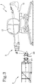
- the machine shown in the drawings is a rotary telehandler 1, equipped with a telescopic lifting arm 11 mounted on the rotatable platform 12, which also has the driver's cab 13, the arm being equipped, at its distal end, with an apparatus 2.
- the invention can be used with a different type of operating machine, generally equipped with a lifting arm and an apparatus.
- the machine in which the invention is implemented may be a fixed telehandler or an articulated telehandler or an operating machine different from telehandlers.
- apparatus 2 means both an accessory for engaging a load, such as a fork, a lateral transfer device, a winch, a gripper, etc. and an accessory for lifting persons and, if necessary, also a load, such as a cage.
- a load such as a fork, a lateral transfer device, a winch, a gripper, etc.
- an accessory for lifting persons and, if necessary, also a load such as a cage.
- the arm 11 may have, at its distal end, an attachment device 110, also of the type normally in use in the telehandlers made by the Applicant, which allows the replacement of the apparatus 2 and its connection to the hydraulic and electronic apparatuses of the machine.
- an attachment device 110 also of the type normally in use in the telehandlers made by the Applicant, which allows the replacement of the apparatus 2 and its connection to the hydraulic and electronic apparatuses of the machine.
- the arm 11 is articulated to the rotatable platform 12, so as to oscillate vertically, under the actuation of a hydraulic cylinder or similar actuator, between a lower position, substantially horizontal, and an upper position wherein the arm 11 is close to the vertical.
- the arm 11 is extensible and retractable and, more precisely, comprises a plurality of segments inserted one in the other, coaxial with each other and designed to translate along the axial direction.
- the elongation and retraction of the arm 11 are also produced by one or more hydraulic cylinders, or other actuators.
- the rotation of the platform 12 is also produced by a preferably hydraulic actuator, associated for example with a rack, in the same way that it is preferably that the actuator which moves the equipment relative to one or more of its joints is hydraulic.
- the hydraulic actuators are subjected to an electro-hydraulic distributor 14, mounted on the machine 1, which is controlled by means of the commands present in the cab 13, according to known methods.
- the machine 1 includes a known control system equipped with commands in the cab 13, such as joystick, pedals, pushbuttons, etc., actuated by the operator; by acting on the commands, signals received from the distributor 14 are generated which then adjusts the operation of the actuators of the arm 11, of the apparatus 2 and of the platform 13 (or of other movable elements).
- commands in the cab 13 such as joystick, pedals, pushbuttons, etc.
- the invention also relates to the case in which the drive actuators are of the electro-mechanical and non-hydraulic type.
- the invention is configured as an improved safety system which, like the prior art systems described in the introduction, is correlated with the loads moved and is designed for the safety of the movements of the vehicle 1; in detail, the safety system makes it possible to move the loads in compliance with the load diagrams, of known type, and prevents the occurrence of an instability of the vehicle 1, for example of the front type.
- the safety system comprises a processing unit 3 which includes a memory module 31 in which is recorded a plurality of load diagrams, or in any case information or instructions corresponding to a plurality of load diagrams.
- the processing unit 3 also comprises a limiting module 32 configured for limiting the possibility of operation of actuators of the machine 1 on the basis of a load diagram selected from those of the memory module 31.
- a limiting module 32 configured for limiting the possibility of operation of actuators of the machine 1 on the basis of a load diagram selected from those of the memory module 31.
- the processing unit 3 may consist of a single electronic device, also of the type commonly present on this type of machine, suitably programmed to perform the functions described; the various modules can correspond to hardware units and/or software forming part of the programmed device.
- the functions can be performed by a plurality of electronic devices on which the above-mentioned functional modules can be distributed.
- the processing unit 3 may have one or more microprocessors or microcontrollers for execution of the instructions contained in the memory modules and the above-mentioned functional modules may also be distributed on a plurality of local or remote calculators based on the architecture of the network on which they are housed.
- the proposed safety system then includes one or more measuring devices 41, 42 for acquiring operating parameters relative to various operating conditions of the operating machine 1.
- the processing unit 3 also includes a selection module 33, which is configured for selecting from the memory module 31 a specific load diagram on the basis of the operating parameter acquired by the above-mentioned measuring device 41, 42, so as to provide to the limiting module 32 the load diagram selected.
- the safety system will apply a particular load diagram to the movements of the machine 1, for example to those of the arm 11, the tower 12 or the apparatus 2, thereby avoiding the limits suffered by the prior art systems.
- the operational condition may mean a particular mode of use of the apparatus 2 or the replacement of the apparatus 2 or a particular shape of the ground on which the machine 1 works, or a new configuration of the machine 1, etc.
- the measuring devices include or consist of relative sensors 41, 42 which acquire a physical quantity which corresponds to the operating parameter and transmit to the processing unit 3 signals which are a function of the acquisition performed.
- the processing unit selects the loading diagram selected and consequently commands the distributor 14 which in turn controls the actuators by suitably constraining the movements.
- the sensors 41, 42 may be of different types on the basis of the apparatus 2 or the various operating conditions which are provided for by the manufacturer.
- a loading cage 21 of the type comprising a bottom surface 210, designed for supporting the operators and/or their work tools, associated with side walls which are located at the perimeter of the surface 210, from which they extend to define a sort of cage open at the top.
- the frame 21 is then equipped with an attachment device 211 designed for anchoring to the attachment device 110 of the arm 11, in a known manner.
- sensors may be included, such as extensometer pins 41, between the attachment device 211 and the rear side wall of the cage 21 and/or sensors may be positioned, such as load cells (not illustrated), at the shock absorbing system 2110 which the attachment device 211 is equipped with.
- the safety system automatically selects the correct diagram, thus avoiding not only operations which are risky for the stability but also excessively stringent limitations.
- safety system By using the safety system according to the invention, user companies can avoid purchasing a plurality of "specialised" cages for various activities, for example for transporting only persons or also for transporting a load, with obvious advantages in terms of economic and working efficiency.
- the sensors might also be located on the base surface 210 of the frame 21 or at different points on the attachment device 211 or in other positions.
- the sensors 41, 42 may be mounted in different positions on the apparatus 2 or even also on the lifting arm 11.
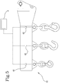
- the apparatus is an arm with several hooks 22, such as that shown in Figure 5
- its various hooks may be operatively associated with respective measuring devices, such as load cells 42 or other sensors.
- the invention will select the correct diagram on the basis of the hook which is each time used to perform the lifting activities.
- the detection device may be a sensor designed to detect whether the arm is in an extended configuration or in a retracted configuration; the sensor in question may be a position sensor or an encoder associated with a cable fixed to the arm, etc.
- the winch of the arm is also associated with a sensor for measuring the load or how much the hook is away from the end of its stroke, that is to say, in its completely raised position, etc.
- the above-mentioned memory module 31 includes several sets of load diagrams for respective apparatuses, whilst the processing unit 3 also comprises an apparatus module 34 configured for selecting the set from which to select the diagram to be used, on the basis of the apparatus 2 attached to the arm.
- the invention may include a device 5 for recognising the apparatus 2 coupled to the arm 11, connected to the processing unit 3 to which the apparatus module 34 is linked.
- the recognition device 5 may be designed for wireless communication and operate at radio frequency, such as a RFID or a Bluetooth transceiver or it may use optical technology, such as the reading of a bar code, or a physical connection of the electrical type, by means of jacks, pins or the like.
- radio frequency such as a RFID or a Bluetooth transceiver
- optical technology such as the reading of a bar code, or a physical connection of the electrical type, by means of jacks, pins or the like.
- the safety system recovers the diagram designed for that type of apparatus 2, for example forks rather than a cage, and may also select a specific diagram for particular examples in the context of that type of apparatus, that is to say, the particular cage designed to carry a certain maximum load, or jib with a certain number of hooks etc.
- the system according to the invention may integrate the recognition of the apparatus 2 with the measurements of the above-mentioned sensors 41, 42.
- the invention is also configured as a method for the safety of a self-propelled operating machine 1, in particular of the type described above.
- the method comprises the following steps:
- the above-mentioned operating parameter may be a load value measured on the apparatus 2 carried by a lifting arm 11 of the machine 1 or a position value measured on the apparatus 2.
- the invention also relates to a computer program which, running on a processing unit 3, executes the steps of the method proposed.
Landscapes
- Engineering & Computer Science (AREA)
- Mechanical Engineering (AREA)
- Structural Engineering (AREA)
- Geology (AREA)
- Life Sciences & Earth Sciences (AREA)
- Transportation (AREA)
- Physics & Mathematics (AREA)
- General Physics & Mathematics (AREA)
- Civil Engineering (AREA)
- General Engineering & Computer Science (AREA)
- Remote Sensing (AREA)
- Radar, Positioning & Navigation (AREA)
- Control And Safety Of Cranes (AREA)
- Forklifts And Lifting Vehicles (AREA)
- Manipulator (AREA)
- Safety Devices In Control Systems (AREA)
- Jib Cranes (AREA)
- Control Of Position, Course, Altitude, Or Attitude Of Moving Bodies (AREA)
- Lighting Device Outwards From Vehicle And Optical Signal (AREA)
Priority Applications (2)
| Application Number | Priority Date | Filing Date | Title |
|---|---|---|---|
| PL19210478T PL3666720T3 (pl) | 2018-12-10 | 2019-11-20 | System bezpieczeństwa dla samobieżnych maszyn roboczych |
| HRP20211259TT HRP20211259T1 (hr) | 2018-12-10 | 2021-08-04 | Sigurnosni sustav za samohodne radne strojeve |
Applications Claiming Priority (1)
| Application Number | Priority Date | Filing Date | Title |
|---|---|---|---|
| IT102018000010918A IT201800010918A1 (it) | 2018-12-10 | 2018-12-10 | Sistema di sicurezza perfezionato per macchine operatrici semoventi. |
Publications (2)
| Publication Number | Publication Date |
|---|---|
| EP3666720A1 EP3666720A1 (en) | 2020-06-17 |
| EP3666720B1 true EP3666720B1 (en) | 2021-06-30 |
Family
ID=65861535
Family Applications (1)
| Application Number | Title | Priority Date | Filing Date |
|---|---|---|---|
| EP19210478.4A Active EP3666720B1 (en) | 2018-12-10 | 2019-11-20 | Safety system for self-propelled operating machines |
Country Status (15)
| Country | Link |
|---|---|
| US (1) | US11866303B2 (pl) |
| EP (1) | EP3666720B1 (pl) |
| CN (1) | CN111285305B (pl) |
| AU (1) | AU2019271935B2 (pl) |
| BR (1) | BR102019025884A2 (pl) |
| CA (1) | CA3062342A1 (pl) |
| DK (1) | DK3666720T3 (pl) |
| ES (1) | ES2885692T3 (pl) |
| HR (1) | HRP20211259T1 (pl) |
| HU (1) | HUE055281T2 (pl) |
| IT (1) | IT201800010918A1 (pl) |
| MX (1) | MX2019014790A (pl) |
| PL (1) | PL3666720T3 (pl) |
| PT (1) | PT3666720T (pl) |
| ZA (1) | ZA201907951B (pl) |
Cited By (2)
| Publication number | Priority date | Publication date | Assignee | Title |
|---|---|---|---|---|
| IT202300015345A1 (it) * | 2023-07-21 | 2025-01-21 | Manitou Italia Srl | Sistema di sicurezza per macchina operatrice |
| IT202300015342A1 (it) * | 2023-07-21 | 2025-01-21 | Manitou Italia Srl | Sistema di sicurezza per macchina operatrice |
Families Citing this family (19)
| Publication number | Priority date | Publication date | Assignee | Title |
|---|---|---|---|---|
| FR3112882B1 (fr) | 2020-07-23 | 2023-07-14 | Manitou Bf | Machine de manutention a bras et procede d’avertissement correspondant |
| USD1013586S1 (en) | 2021-04-02 | 2024-02-06 | Manitou Italia S.R.L. | Protective grille for vehicle |
| CA206853S (en) | 2021-04-02 | 2023-07-20 | Manitou Italia Srl | Telescopic handler |
| USD982043S1 (en) | 2021-04-02 | 2023-03-28 | Manitou Italia S.R.L. | Ballast |
| EP4119491A1 (en) * | 2021-07-16 | 2023-01-18 | TOYOTA MATERIAL HANDLING MANUFACTURING ITALY S.p.A | Industrial truck capable of recognizing a material handling apparatus |
| CA3171550A1 (en) * | 2021-09-06 | 2023-03-06 | Manitou Italia S.R.L. | Telehandler with improved winch |
| USD1020812S1 (en) | 2021-11-18 | 2024-04-02 | Manitou Italia S.R.L. | Cabin for telescopic lifter |
| USD998835S1 (en) | 2021-11-18 | 2023-09-12 | Manitou Italia S.R.L. | Headlight for telescopic lifter |
| USD1005637S1 (en) | 2021-11-18 | 2023-11-21 | Manitou Italia S.R.L. | Turret for telescopic lifter |
| USD1048115S1 (en) | 2021-11-19 | 2024-10-22 | Manitou Italia S.R.L. | Cabin hood for a vehicle with a telescopic lifter |
| USD1026047S1 (en) | 2021-11-19 | 2024-05-07 | Manitou Italia S.R.L. | Visor for telescopic lifter |
| USD1060439S1 (en) | 2021-11-19 | 2025-02-04 | Manitou Italia S.R.L. | Console with hand controls for telescopic lifter |
| USD1063289S1 (en) | 2021-12-29 | 2025-02-18 | Manitou Italia S.R.L. | Ladder for telescopic lifter |
| USD1070223S1 (en) | 2021-12-29 | 2025-04-08 | Manitou Italia S.R.L. | Part of cabin for telescopic lifter |
| USD1103224S1 (en) | 2022-02-02 | 2025-11-25 | Manitou Italia S.R.L. | Handles for telescopic lifter |
| USD1086632S1 (en) | 2022-02-08 | 2025-07-29 | Manitou Italia S.R.L. | Cabin hood for a vehicle with a telescopic lifter |
| USD1060923S1 (en) | 2022-02-08 | 2025-02-04 | Manitou Italia S.R.L. | Platform for telescopic lifter |
| USD995578S1 (en) | 2022-02-08 | 2023-08-15 | Manitou Italia S.R.L. | Cabin for telescopic lifter |
| IT202400001794A1 (it) * | 2024-01-30 | 2025-07-30 | Dieci S R L | Telehandler |
Family Cites Families (28)
| Publication number | Priority date | Publication date | Assignee | Title |
|---|---|---|---|---|
| GB1358871A (en) * | 1971-06-25 | 1974-07-03 | Pye Ltd | Crane load indicator arrangement |
| GB1500501A (en) * | 1974-04-10 | 1978-02-08 | Pye Ltd | Crane load indicating arrangement |
| US4052602A (en) * | 1975-08-14 | 1977-10-04 | Forney Engineering Company | Load and radius indicating system |
| US4054055A (en) * | 1976-08-06 | 1977-10-18 | Precilec | Device for controlling the load of a lifting appliance |
| FR2390366A1 (fr) * | 1977-05-13 | 1978-12-08 | Preux Roger | Controleur d'etat de charge, notamment pour engin de levage |
| EP0036455A1 (en) * | 1980-03-18 | 1981-09-30 | Liner Limited | Improved load handling vehicle |
| US5143232A (en) * | 1991-09-18 | 1992-09-01 | Stewart James T | Crane load instrument and method therefor |
| US5263597A (en) * | 1991-09-18 | 1993-11-23 | Stewart James T | Crane load instrument and method therefor |
| JP2564060B2 (ja) * | 1991-10-24 | 1996-12-18 | 株式会社神戸製鋼所 | 建設機械の安全装置 |
| JPH07165391A (ja) * | 1993-12-14 | 1995-06-27 | Yutani Heavy Ind Ltd | 関節式クレーンの荷重検出方法 |
| US5591943A (en) * | 1994-06-10 | 1997-01-07 | Cheng; Liang-Chieh | Weight-sensing member for an electrical suspension weigher |
| US6303882B1 (en) * | 2000-03-10 | 2001-10-16 | Cranium Corporation | Load cell apparatus and method |
| US20070266601A1 (en) * | 2006-05-19 | 2007-11-22 | Claxton Richard L | Device for measuring a load at the end of a rope wrapped over a rod |
| CN101439825B (zh) * | 2008-12-23 | 2011-07-20 | 三一集团有限公司 | 一种起重机吊具发电系统、起重机吊具及起重机 |
| CN101780926B (zh) * | 2010-01-07 | 2012-05-09 | 上海三一科技有限公司 | 履带起重机力矩限制系统 |
| CA2692894C (en) * | 2010-02-12 | 2017-06-27 | Bhm Medical Inc. | Lift apparatus and system |
| DE102010025022A1 (de) * | 2010-06-24 | 2011-12-29 | Hirschmann Automation And Control Gmbh | Verfahren zur Lastmomentbegrenzung eines Arbeitsfahrzeuges mit einem Ausleger |
| DE202010014309U1 (de) * | 2010-10-14 | 2012-01-18 | Liebherr-Werk Ehingen Gmbh | Kran, insbesondere Raupen- oder Mobilkran |
| CN102826452A (zh) * | 2011-07-22 | 2012-12-19 | 广州市特种机电设备检测研究院 | 起重机载荷谱数据获取系统、方法以及疲劳寿命评估系统 |
| CN103552929B (zh) * | 2013-11-12 | 2015-04-29 | 徐工集团工程机械股份有限公司 | 基于负载的履带起重机发动机控制方法和装置 |
| DK2982639T3 (en) * | 2014-08-04 | 2018-12-17 | Manitou Italia Srl | LATERAL STABILIZATION SYSTEM |
| CN108137297B (zh) * | 2015-06-12 | 2020-07-10 | 马尼托瓦克起重机有限责任公司 | 用于计算在中间配重位置处的负载能力图的系统和方法 |
| DE102016104358B4 (de) * | 2016-03-10 | 2019-11-07 | Manitowoc Crane Group France Sas | Verfahren zum Ermitteln der Tragfähigkeit eines Krans sowie Kran |
| KR101921196B1 (ko) * | 2016-12-13 | 2019-02-13 | 주식회사 수산중공업 | 크레인 안전 장치 및 그 제어 방법 |
| US11142438B2 (en) * | 2017-08-28 | 2021-10-12 | Manitowoc Crane Companies, Llc | Graphical working range diagrams for displaying allowable and projected loads |
| CN107857212B (zh) * | 2017-09-26 | 2019-06-25 | 林德(中国)叉车有限公司 | 一种叉车最大举升高度限制方法及系统 |
| CN107628545B (zh) * | 2017-11-01 | 2019-07-12 | 上海振华重工(集团)股份有限公司 | 一种海上起重机的力矩限制系统 |
| IT201900012957A1 (it) * | 2019-07-25 | 2021-01-25 | Manitou Italia Srl | Braccetto a più ganci perfezionato. |
-
2018
- 2018-12-10 IT IT102018000010918A patent/IT201800010918A1/it unknown
-
2019
- 2019-11-20 PL PL19210478T patent/PL3666720T3/pl unknown
- 2019-11-20 ES ES19210478T patent/ES2885692T3/es active Active
- 2019-11-20 DK DK19210478.4T patent/DK3666720T3/da active
- 2019-11-20 EP EP19210478.4A patent/EP3666720B1/en active Active
- 2019-11-20 HU HUE19210478A patent/HUE055281T2/hu unknown
- 2019-11-20 PT PT192104784T patent/PT3666720T/pt unknown
- 2019-11-22 CA CA3062342A patent/CA3062342A1/en active Pending
- 2019-11-26 AU AU2019271935A patent/AU2019271935B2/en active Active
- 2019-11-27 US US16/698,123 patent/US11866303B2/en active Active
- 2019-11-29 ZA ZA2019/07951A patent/ZA201907951B/en unknown
- 2019-12-06 BR BR102019025884-5A patent/BR102019025884A2/pt active IP Right Grant
- 2019-12-09 MX MX2019014790A patent/MX2019014790A/es unknown
- 2019-12-09 CN CN201911252317.3A patent/CN111285305B/zh active Active
-
2021
- 2021-08-04 HR HRP20211259TT patent/HRP20211259T1/hr unknown
Cited By (4)
| Publication number | Priority date | Publication date | Assignee | Title |
|---|---|---|---|---|
| IT202300015345A1 (it) * | 2023-07-21 | 2025-01-21 | Manitou Italia Srl | Sistema di sicurezza per macchina operatrice |
| IT202300015342A1 (it) * | 2023-07-21 | 2025-01-21 | Manitou Italia Srl | Sistema di sicurezza per macchina operatrice |
| EP4495050A1 (en) * | 2023-07-21 | 2025-01-22 | Manitou Italia S.r.l. | Safety system for working machine |
| EP4516720A1 (en) * | 2023-07-21 | 2025-03-05 | Manitou Italia S.r.l. | Safety system for working machine |
Also Published As
| Publication number | Publication date |
|---|---|
| HRP20211259T1 (hr) | 2021-11-12 |
| RU2019139412A (ru) | 2021-06-04 |
| AU2019271935A1 (en) | 2020-06-25 |
| CA3062342A1 (en) | 2020-06-10 |
| ES2885692T3 (es) | 2021-12-15 |
| PL3666720T3 (pl) | 2021-12-13 |
| PT3666720T (pt) | 2021-07-23 |
| AU2019271935B2 (en) | 2025-09-18 |
| DK3666720T3 (da) | 2021-08-23 |
| ZA201907951B (en) | 2020-12-23 |
| CN111285305B (zh) | 2022-08-30 |
| HUE055281T2 (hu) | 2021-11-29 |
| EP3666720A1 (en) | 2020-06-17 |
| MX2019014790A (es) | 2020-11-12 |
| US20200180916A1 (en) | 2020-06-11 |
| US11866303B2 (en) | 2024-01-09 |
| IT201800010918A1 (it) | 2020-06-10 |
| CN111285305A (zh) | 2020-06-16 |
| BR102019025884A2 (pt) | 2020-06-23 |
Similar Documents
| Publication | Publication Date | Title |
|---|---|---|
| EP3666720B1 (en) | Safety system for self-propelled operating machines | |
| CN109205515B (zh) | 用于使自行式操作机器稳定的系统 | |
| AU2019202156B2 (en) | Articulated self-propelled work machine | |
| CN115771847A (zh) | 伸缩臂叉车 | |
| JP7695938B2 (ja) | クレーンを監視するためのシステム及び方法、並びにそれらを有するクレーン | |
| US11679970B2 (en) | Telehandler with control system | |
| EP4495050A1 (en) | Safety system for working machine | |
| EP3770101B1 (en) | Arm with two or more hooks | |
| RU2800941C2 (ru) | Усовершенствованная система безопасности для самоходных рабочих машин | |
| RU2831614C2 (ru) | Моделирующее устройство для телескопических погрузчиков | |
| RU2810831C2 (ru) | Усовершенствованная стрела с двумя или более крюками | |
| EP4516720A1 (en) | Safety system for working machine | |
| JP2002255495A (ja) | 高所作業車の荷重検出装置 |
Legal Events
| Date | Code | Title | Description |
|---|---|---|---|
| PUAI | Public reference made under article 153(3) epc to a published international application that has entered the european phase |
Free format text: ORIGINAL CODE: 0009012 |
|
| STAA | Information on the status of an ep patent application or granted ep patent |
Free format text: STATUS: THE APPLICATION HAS BEEN PUBLISHED |
|
| AK | Designated contracting states |
Kind code of ref document: A1 Designated state(s): AL AT BE BG CH CY CZ DE DK EE ES FI FR GB GR HR HU IE IS IT LI LT LU LV MC MK MT NL NO PL PT RO RS SE SI SK SM TR |
|
| AX | Request for extension of the european patent |
Extension state: BA ME |
|
| STAA | Information on the status of an ep patent application or granted ep patent |
Free format text: STATUS: REQUEST FOR EXAMINATION WAS MADE |
|
| 17P | Request for examination filed |
Effective date: 20201217 |
|
| RBV | Designated contracting states (corrected) |
Designated state(s): AL AT BE BG CH CY CZ DE DK EE ES FI FR GB GR HR HU IE IS IT LI LT LU LV MC MK MT NL NO PL PT RO RS SE SI SK SM TR |
|
| GRAP | Despatch of communication of intention to grant a patent |
Free format text: ORIGINAL CODE: EPIDOSNIGR1 |
|
| STAA | Information on the status of an ep patent application or granted ep patent |
Free format text: STATUS: GRANT OF PATENT IS INTENDED |
|
| RIC1 | Information provided on ipc code assigned before grant |
Ipc: B66F 9/065 20060101AFI20210312BHEP Ipc: B66F 17/00 20060101ALI20210312BHEP |
|
| INTG | Intention to grant announced |
Effective date: 20210414 |
|
| GRAS | Grant fee paid |
Free format text: ORIGINAL CODE: EPIDOSNIGR3 |
|
| GRAA | (expected) grant |
Free format text: ORIGINAL CODE: 0009210 |
|
| STAA | Information on the status of an ep patent application or granted ep patent |
Free format text: STATUS: THE PATENT HAS BEEN GRANTED |
|
| AK | Designated contracting states |
Kind code of ref document: B1 Designated state(s): AL AT BE BG CH CY CZ DE DK EE ES FI FR GB GR HR HU IE IS IT LI LT LU LV MC MK MT NL NO PL PT RO RS SE SI SK SM TR |
|
| REG | Reference to a national code |
Ref country code: CH Ref legal event code: EP |
|
| REG | Reference to a national code |
Ref country code: DE Ref legal event code: R096 Ref document number: 602019005762 Country of ref document: DE Ref country code: AT Ref legal event code: REF Ref document number: 1406214 Country of ref document: AT Kind code of ref document: T Effective date: 20210715 |
|
| REG | Reference to a national code |
Ref country code: PT Ref legal event code: SC4A Ref document number: 3666720 Country of ref document: PT Date of ref document: 20210723 Kind code of ref document: T Free format text: AVAILABILITY OF NATIONAL TRANSLATION Effective date: 20210720 |
|
| REG | Reference to a national code |
Ref country code: HR Ref legal event code: TUEP Ref document number: P20211259T Country of ref document: HR Ref country code: IE Ref legal event code: FG4D |
|
| REG | Reference to a national code |
Ref country code: NL Ref legal event code: FP |
|
| REG | Reference to a national code |
Ref country code: DK Ref legal event code: T3 Effective date: 20210819 |
|
| REG | Reference to a national code |
Ref country code: FI Ref legal event code: FGE |
|
| REG | Reference to a national code |
Ref country code: SE Ref legal event code: TRGR |
|
| REG | Reference to a national code |
Ref country code: NO Ref legal event code: T2 Effective date: 20210630 |
|
| REG | Reference to a national code |
Ref country code: LT Ref legal event code: MG9D |
|
| PG25 | Lapsed in a contracting state [announced via postgrant information from national office to epo] |
Ref country code: BG Free format text: LAPSE BECAUSE OF FAILURE TO SUBMIT A TRANSLATION OF THE DESCRIPTION OR TO PAY THE FEE WITHIN THE PRESCRIBED TIME-LIMIT Effective date: 20210930 |
|
| REG | Reference to a national code |
Ref country code: GR Ref legal event code: EP Ref document number: 20210402391 Country of ref document: GR Effective date: 20211013 |
|
| REG | Reference to a national code |
Ref country code: HR Ref legal event code: T1PR Ref document number: P20211259 Country of ref document: HR |
|
| REG | Reference to a national code |
Ref country code: HR Ref legal event code: ODRP Ref document number: P20211259 Country of ref document: HR Payment date: 20211102 Year of fee payment: 3 |
|
| REG | Reference to a national code |
Ref country code: HU Ref legal event code: AG4A Ref document number: E055281 Country of ref document: HU |
|
| PG25 | Lapsed in a contracting state [announced via postgrant information from national office to epo] |
Ref country code: LV Free format text: LAPSE BECAUSE OF FAILURE TO SUBMIT A TRANSLATION OF THE DESCRIPTION OR TO PAY THE FEE WITHIN THE PRESCRIBED TIME-LIMIT Effective date: 20210630 Ref country code: RS Free format text: LAPSE BECAUSE OF FAILURE TO SUBMIT A TRANSLATION OF THE DESCRIPTION OR TO PAY THE FEE WITHIN THE PRESCRIBED TIME-LIMIT Effective date: 20210630 |
|
| REG | Reference to a national code |
Ref country code: ES Ref legal event code: FG2A Ref document number: 2885692 Country of ref document: ES Kind code of ref document: T3 Effective date: 20211215 |
|
| PG25 | Lapsed in a contracting state [announced via postgrant information from national office to epo] |
Ref country code: SM Free format text: LAPSE BECAUSE OF FAILURE TO SUBMIT A TRANSLATION OF THE DESCRIPTION OR TO PAY THE FEE WITHIN THE PRESCRIBED TIME-LIMIT Effective date: 20210630 Ref country code: RO Free format text: LAPSE BECAUSE OF FAILURE TO SUBMIT A TRANSLATION OF THE DESCRIPTION OR TO PAY THE FEE WITHIN THE PRESCRIBED TIME-LIMIT Effective date: 20210630 Ref country code: SK Free format text: LAPSE BECAUSE OF FAILURE TO SUBMIT A TRANSLATION OF THE DESCRIPTION OR TO PAY THE FEE WITHIN THE PRESCRIBED TIME-LIMIT Effective date: 20210630 Ref country code: EE Free format text: LAPSE BECAUSE OF FAILURE TO SUBMIT A TRANSLATION OF THE DESCRIPTION OR TO PAY THE FEE WITHIN THE PRESCRIBED TIME-LIMIT Effective date: 20210630 |
|
| REG | Reference to a national code |
Ref country code: DE Ref legal event code: R097 Ref document number: 602019005762 Country of ref document: DE |
|
| PLBE | No opposition filed within time limit |
Free format text: ORIGINAL CODE: 0009261 |
|
| STAA | Information on the status of an ep patent application or granted ep patent |
Free format text: STATUS: NO OPPOSITION FILED WITHIN TIME LIMIT |
|
| PG25 | Lapsed in a contracting state [announced via postgrant information from national office to epo] |
Ref country code: AL Free format text: LAPSE BECAUSE OF FAILURE TO SUBMIT A TRANSLATION OF THE DESCRIPTION OR TO PAY THE FEE WITHIN THE PRESCRIBED TIME-LIMIT Effective date: 20210630 |
|
| 26N | No opposition filed |
Effective date: 20220331 |
|
| REG | Reference to a national code |
Ref country code: HR Ref legal event code: ODRP Ref document number: P20211259 Country of ref document: HR Payment date: 20221103 Year of fee payment: 4 |
|
| REG | Reference to a national code |
Ref country code: AT Ref legal event code: UEP Ref document number: 1406214 Country of ref document: AT Kind code of ref document: T Effective date: 20210630 |
|
| PG25 | Lapsed in a contracting state [announced via postgrant information from national office to epo] |
Ref country code: LT Free format text: LAPSE BECAUSE OF FAILURE TO SUBMIT A TRANSLATION OF THE DESCRIPTION OR TO PAY THE FEE WITHIN THE PRESCRIBED TIME-LIMIT Effective date: 20210630 |
|
| PG25 | Lapsed in a contracting state [announced via postgrant information from national office to epo] |
Ref country code: CY Free format text: LAPSE BECAUSE OF FAILURE TO SUBMIT A TRANSLATION OF THE DESCRIPTION OR TO PAY THE FEE WITHIN THE PRESCRIBED TIME-LIMIT Effective date: 20210630 |
|
| P01 | Opt-out of the competence of the unified patent court (upc) registered |
Effective date: 20230526 |
|
| REG | Reference to a national code |
Ref country code: HR Ref legal event code: ODRP Ref document number: P20211259 Country of ref document: HR Payment date: 20231102 Year of fee payment: 5 |
|
| PG25 | Lapsed in a contracting state [announced via postgrant information from national office to epo] |
Ref country code: MK Free format text: LAPSE BECAUSE OF FAILURE TO SUBMIT A TRANSLATION OF THE DESCRIPTION OR TO PAY THE FEE WITHIN THE PRESCRIBED TIME-LIMIT Effective date: 20210630 |
|
| PG25 | Lapsed in a contracting state [announced via postgrant information from national office to epo] |
Ref country code: MT Free format text: LAPSE BECAUSE OF FAILURE TO SUBMIT A TRANSLATION OF THE DESCRIPTION OR TO PAY THE FEE WITHIN THE PRESCRIBED TIME-LIMIT Effective date: 20210630 |
|
| REG | Reference to a national code |
Ref country code: HR Ref legal event code: ODRP Ref document number: P20211259 Country of ref document: HR Payment date: 20241030 Year of fee payment: 6 |
|
| REG | Reference to a national code |
Ref country code: HR Ref legal event code: ODRP Ref document number: P20211259 Country of ref document: HR Payment date: 20251030 Year of fee payment: 7 |
|
| REG | Reference to a national code |
Ref country code: CH Ref legal event code: U11 Free format text: ST27 STATUS EVENT CODE: U-0-0-U10-U11 (AS PROVIDED BY THE NATIONAL OFFICE) Effective date: 20251201 |
|
| PGFP | Annual fee paid to national office [announced via postgrant information from national office to epo] |
Ref country code: PT Payment date: 20251104 Year of fee payment: 7 |
|
| PGFP | Annual fee paid to national office [announced via postgrant information from national office to epo] |
Ref country code: HU Payment date: 20251112 Year of fee payment: 7 |
|
| PGFP | Annual fee paid to national office [announced via postgrant information from national office to epo] |
Ref country code: LU Payment date: 20251124 Year of fee payment: 7 Ref country code: NL Payment date: 20251124 Year of fee payment: 7 |
|
| PGFP | Annual fee paid to national office [announced via postgrant information from national office to epo] |
Ref country code: DE Payment date: 20251126 Year of fee payment: 7 |
|
| PGFP | Annual fee paid to national office [announced via postgrant information from national office to epo] |
Ref country code: GB Payment date: 20251125 Year of fee payment: 7 |
|
| PGFP | Annual fee paid to national office [announced via postgrant information from national office to epo] |
Ref country code: NO Payment date: 20251120 Year of fee payment: 7 Ref country code: MC Payment date: 20251120 Year of fee payment: 7 |
|
| PGFP | Annual fee paid to national office [announced via postgrant information from national office to epo] |
Ref country code: AT Payment date: 20251118 Year of fee payment: 7 |
|
| PGFP | Annual fee paid to national office [announced via postgrant information from national office to epo] |
Ref country code: IT Payment date: 20251128 Year of fee payment: 7 Ref country code: FI Payment date: 20251124 Year of fee payment: 7 Ref country code: DK Payment date: 20251124 Year of fee payment: 7 |
|
| PGFP | Annual fee paid to national office [announced via postgrant information from national office to epo] |
Ref country code: HR Payment date: 20251030 Year of fee payment: 7 Ref country code: FR Payment date: 20251124 Year of fee payment: 7 |
|
| PGFP | Annual fee paid to national office [announced via postgrant information from national office to epo] |
Ref country code: TR Payment date: 20251031 Year of fee payment: 7 Ref country code: GR Payment date: 20251118 Year of fee payment: 7 Ref country code: BE Payment date: 20251124 Year of fee payment: 7 |
|
| PGFP | Annual fee paid to national office [announced via postgrant information from national office to epo] |
Ref country code: CH Payment date: 20251201 Year of fee payment: 7 Ref country code: SE Payment date: 20251124 Year of fee payment: 7 |
|
| PGFP | Annual fee paid to national office [announced via postgrant information from national office to epo] |
Ref country code: IE Payment date: 20251118 Year of fee payment: 7 Ref country code: CZ Payment date: 20251111 Year of fee payment: 7 |
|
| PGFP | Annual fee paid to national office [announced via postgrant information from national office to epo] |
Ref country code: PL Payment date: 20251023 Year of fee payment: 7 |
|
| PGFP | Annual fee paid to national office [announced via postgrant information from national office to epo] |
Ref country code: ES Payment date: 20251209 Year of fee payment: 7 |