EP3666704A2 - Car to car wireless power transfer - Google Patents
Car to car wireless power transfer Download PDFInfo
- Publication number
- EP3666704A2 EP3666704A2 EP19215388.0A EP19215388A EP3666704A2 EP 3666704 A2 EP3666704 A2 EP 3666704A2 EP 19215388 A EP19215388 A EP 19215388A EP 3666704 A2 EP3666704 A2 EP 3666704A2
- Authority
- EP
- European Patent Office
- Prior art keywords
- electrical power
- conveyance
- wireless electrical
- wireless
- conveyance system
- Prior art date
- Legal status (The legal status is an assumption and is not a legal conclusion. Google has not performed a legal analysis and makes no representation as to the accuracy of the status listed.)
- Granted
Links
Images

Classifications
-
- B—PERFORMING OPERATIONS; TRANSPORTING
- B66—HOISTING; LIFTING; HAULING
- B66B—ELEVATORS; ESCALATORS OR MOVING WALKWAYS
- B66B11/00—Main component parts of lifts in, or associated with, buildings or other structures
- B66B11/02—Cages, i.e. cars
- B66B11/0226—Constructional features, e.g. walls assembly, decorative panels, comfort equipment, thermal or sound insulation
-
- B—PERFORMING OPERATIONS; TRANSPORTING
- B66—HOISTING; LIFTING; HAULING
- B66B—ELEVATORS; ESCALATORS OR MOVING WALKWAYS
- B66B7/00—Other common features of elevators
-
- H—ELECTRICITY
- H02—GENERATION; CONVERSION OR DISTRIBUTION OF ELECTRIC POWER
- H02J—ELECTRIC POWER NETWORKS; CIRCUIT ARRANGEMENTS OR SYSTEMS FOR SUPPLYING OR DISTRIBUTING ELECTRIC POWER; SYSTEMS FOR STORING ELECTRIC ENERGY
- H02J50/00—Circuit arrangements or systems for wireless supply or distribution of electric power
-
- H—ELECTRICITY
- H02—GENERATION; CONVERSION OR DISTRIBUTION OF ELECTRIC POWER
- H02J—ELECTRIC POWER NETWORKS; CIRCUIT ARRANGEMENTS OR SYSTEMS FOR SUPPLYING OR DISTRIBUTING ELECTRIC POWER; SYSTEMS FOR STORING ELECTRIC ENERGY
- H02J50/00—Circuit arrangements or systems for wireless supply or distribution of electric power
- H02J50/10—Circuit arrangements or systems for wireless supply or distribution of electric power using inductive coupling
-
- H—ELECTRICITY
- H02—GENERATION; CONVERSION OR DISTRIBUTION OF ELECTRIC POWER
- H02J—ELECTRIC POWER NETWORKS; CIRCUIT ARRANGEMENTS OR SYSTEMS FOR SUPPLYING OR DISTRIBUTING ELECTRIC POWER; SYSTEMS FOR STORING ELECTRIC ENERGY
- H02J50/00—Circuit arrangements or systems for wireless supply or distribution of electric power
- H02J50/40—Circuit arrangements or systems for wireless supply or distribution of electric power using two or more transmitting or receiving devices
-
- H—ELECTRICITY
- H02—GENERATION; CONVERSION OR DISTRIBUTION OF ELECTRIC POWER
- H02J—ELECTRIC POWER NETWORKS; CIRCUIT ARRANGEMENTS OR SYSTEMS FOR SUPPLYING OR DISTRIBUTING ELECTRIC POWER; SYSTEMS FOR STORING ELECTRIC ENERGY
- H02J50/00—Circuit arrangements or systems for wireless supply or distribution of electric power
- H02J50/90—Circuit arrangements or systems for wireless supply or distribution of electric power involving detection or optimisation of position, e.g. alignment
-
- B—PERFORMING OPERATIONS; TRANSPORTING
- B66—HOISTING; LIFTING; HAULING
- B66B—ELEVATORS; ESCALATORS OR MOVING WALKWAYS
- B66B1/00—Control systems of elevators in general
- B66B1/24—Control systems with regulation, i.e. with retroactive action, for influencing travelling speed, acceleration, or deceleration
- B66B1/28—Control systems with regulation, i.e. with retroactive action, for influencing travelling speed, acceleration, or deceleration electrical
- B66B1/30—Control systems with regulation, i.e. with retroactive action, for influencing travelling speed, acceleration, or deceleration electrical effective on driving gear, e.g. acting on power electronics, on inverter or rectifier controlled motor
- B66B1/306—Control systems with regulation, i.e. with retroactive action, for influencing travelling speed, acceleration, or deceleration electrical effective on driving gear, e.g. acting on power electronics, on inverter or rectifier controlled motor with DC powered elevator drive
-
- B—PERFORMING OPERATIONS; TRANSPORTING
- B66—HOISTING; LIFTING; HAULING
- B66B—ELEVATORS; ESCALATORS OR MOVING WALKWAYS
- B66B11/00—Main component parts of lifts in, or associated with, buildings or other structures
-
- B—PERFORMING OPERATIONS; TRANSPORTING
- B66—HOISTING; LIFTING; HAULING
- B66B—ELEVATORS; ESCALATORS OR MOVING WALKWAYS
- B66B2201/00—Aspects of control systems of elevators
- B66B2201/30—Details of the elevator system configuration
-
- H—ELECTRICITY
- H02—GENERATION; CONVERSION OR DISTRIBUTION OF ELECTRIC POWER
- H02J—ELECTRIC POWER NETWORKS; CIRCUIT ARRANGEMENTS OR SYSTEMS FOR SUPPLYING OR DISTRIBUTING ELECTRIC POWER; SYSTEMS FOR STORING ELECTRIC ENERGY
- H02J50/00—Circuit arrangements or systems for wireless supply or distribution of electric power
- H02J50/20—Circuit arrangements or systems for wireless supply or distribution of electric power using microwaves or radio frequency waves
- H02J50/23—Circuit arrangements or systems for wireless supply or distribution of electric power using microwaves or radio frequency waves characterised by the type of transmitting antennas, e.g. directional array antennas or Yagi antennas
-
- H—ELECTRICITY
- H02—GENERATION; CONVERSION OR DISTRIBUTION OF ELECTRIC POWER
- H02J—ELECTRIC POWER NETWORKS; CIRCUIT ARRANGEMENTS OR SYSTEMS FOR SUPPLYING OR DISTRIBUTING ELECTRIC POWER; SYSTEMS FOR STORING ELECTRIC ENERGY
- H02J50/00—Circuit arrangements or systems for wireless supply or distribution of electric power
- H02J50/50—Circuit arrangements or systems for wireless supply or distribution of electric power using additional energy repeaters between transmitting devices and receiving devices
Definitions
- the embodiments herein relate to the field of conveyance systems, and specifically to a method and apparatus for powering a conveyance system.
- Conveyance systems such as, for example, elevator systems, escalator systems, and moving walkways require electrical power for operation.
- Travelling cables typically connect an elevator car of the elevator system to a stationary power source to provide power to the elevator car. Travelling cables add expense, weight, and complexity to elevator car operation and installation, thus improved methods of powering elevator cars are desired.
- a wireless power transfer system for wirelessly powering a conveyance apparatus of a first conveyance system and a conveyance apparatus of a second conveyance system.
- the wireless power transfer system including: a wireless electrical power transceiver located along a surface of the conveyance apparatus of the first conveyance system, a wireless electrical power transceiver located along a surface of the conveyance apparatus of the second conveyance system, the surface of the conveyance apparatus of the second conveyance system being opposite of the surface of the conveyance apparatus of the first conveyance system, wherein the wireless electrical power transceiver of the first conveyance system is configured to wirelessly transfer electrical power to the wireless electrical power transceiver of the second conveyance system when the wireless electrical power transceiver of the first conveyance system and the wireless electrical power transceiver of the second conveyance system are located proximate to one another.
- further embodiments may include that the wireless electrical power transceiver of the first conveyance system and the wireless electrical power transceiver of the second conveyance system are in a facing spaced relationship when the wireless electrical power transceiver of the first conveyance system and the wireless electrical power transceiver of the second conveyance system are located at a first location.
- further embodiments may include that the first conveyance system is a first elevator system and the conveyance apparatus of the first conveyance system is an elevator car, and wherein the second conveyance system is a second elevator system and the conveyance apparatus of the second conveyance system is an elevator car.
- further embodiments may include: a wireless electrical power transmitter located in a second location along the first conveyance system opposite the surface of the conveyance apparatus of the first conveyance system and along the second conveyance system opposite the surface of the conveyance apparatus of the second conveyance system; wherein the wireless electrical power transmitter is configured to wirelessly transmit electrical power to the wireless electrical power transceiver of the first conveyance system when the wireless electrical power transceiver of the first conveyance system is located in the second location.
- further embodiments may include: a wireless electrical power transmitter located in a second location along the first conveyance system opposite the surface of the conveyance apparatus of the first conveyance system and along the second conveyance system opposite the surface of the conveyance apparatus of the second conveyance system, wherein the wireless electrical power transmitter is configured to wirelessly transmit electrical power to the wireless electrical power transceiver of the second conveyance system when the wireless electrical power transceiver of the second conveyance system is located in the first location.
- further embodiments may include: a first electrical coil of the wireless electrical power transmitter adjacent to the wall of the first conveyance system; and a rotational device configured to rotate the wireless electrical power transmitter and the first electrical coil towards the wireless electrical power transceiver of the first conveyance system or wireless electrical power transceiver of the second conveyance system.
- further embodiments may include: a first electrical coil of the wireless electrical power transmitter adjacent to the wall of the first conveyance system; and a second electrical coil of the wireless electrical power transmitter adjacent to the wall of the second conveyance system.
- further embodiments may include that the wireless electrical power transceiver of the first conveyance system and the wireless electrical power transmitter are in a facing spaced relationship defining a gap therebetween when the wireless electrical power transceiver is located at a second location.
- further embodiments may include that the wireless electrical power transceiver of the second conveyance system and the wireless electrical power transmitter are in a facing spaced relationship defining a gap therebetween when the wireless electrical power transceiver is located at a second location.
- further embodiments may include that the first elevator system includes an elevator shaft, and wherein the second elevator system includes an elevator shaft adjacent to the elevator shaft of the first elevator system.
- a system including a first conveyance system and a second conveyance system including: a conveyance apparatus of the first conveyance system; a conveyance apparatus of the second conveyance system; and a wireless power transfer system for wirelessly powering the conveyance apparatus of the first conveyance system and the conveyance apparatus of the second conveyance system, the wireless power transfer system including: a wireless electrical power transceiver located along a surface of the conveyance apparatus of the first conveyance system, a wireless electrical power transceiver located along a surface of the conveyance apparatus of the second conveyance system, surface of the conveyance apparatus of the second conveyance system being opposite of the surface of the conveyance apparatus of the first conveyance system, wherein the wireless electrical power transceiver of the first conveyance system is configured to wirelessly transfer electrical power to the wireless electrical power transceiver of the second conveyance system when the wireless electrical power transceiver of the first conveyance system and the wireless electrical power transceiver of the second conveyance system are located at a first location.
- further embodiments may include that the wireless electrical power transceiver of the first conveyance system and the wireless electrical power transceiver of the second conveyance system are in a facing spaced relationship when the wireless electrical power transceiver of the first conveyance system and the wireless electrical power transceiver of the second conveyance system are located at a first location.
- further embodiments may include that the first conveyance system is a first elevator system and the conveyance apparatus of the first conveyance system is an elevator car, and wherein the second conveyance system is a second elevator system and the conveyance apparatus of the second conveyance system is an elevator car.
- the wireless power transfer system further includes: a wireless electrical power transmitter located in a second location along the first conveyance system opposite the surface of the conveyance apparatus of the first conveyance system and along the second conveyance system opposite the surface of the conveyance apparatus of the second conveyance system; wherein the wireless electrical power transmitter is configured to wirelessly transmit electrical power to the wireless electrical power transceiver of the first conveyance system when the wireless electrical power transceiver of the first conveyance system is located in the second location, and wherein the wireless electrical power transmitter is configured to wirelessly transmit electrical power to the wireless electrical power transceiver of the second conveyance system when the wireless electrical power transceiver of the second conveyance system is located in the first location.
- the wireless power transfer system further includes: a first electrical coil of the wireless electrical power transmitter adjacent to the wall of the first conveyance system; and a rotational device configured to rotate the wireless electrical power transmitter and the first electrical coil towards the wireless electrical power transceiver of the first conveyance system or wireless electrical power transceiver of the second conveyance system.
- the wireless power transfer system further includes: a first electrical coil of the wireless electrical power transmitter adjacent to the wall of the first conveyance system; and a second electrical coil of the wireless electrical power transmitter adjacent to the wall of the second conveyance system.
- further embodiments may include that the wireless electrical power transceiver of the first conveyance system and the wireless electrical power transmitter are in a facing spaced relationship defining a gap therebetween when the wireless electrical power transceiver is located at a second location.
- further embodiments may include that the wireless electrical power transceiver of the second conveyance system and the wireless electrical power transmitter are in a facing spaced relationship defining a gap therebetween when the wireless electrical power transceiver is located at a second location.
- further embodiments may include that the first elevator system includes an elevator shaft, and wherein the second elevator system includes an elevator shaft adjacent to the elevator shaft of the first elevator system.
- a wireless power transfer system for wirelessly powering an elevator car of a first elevator shaft and an elevator car of a second elevator shaft.
- the wireless power transfer system including: a wireless electrical power transceiver located along a surface of the elevator car of the first elevator shaft, a wireless electrical power transceiver located along a surface of the elevator car of the second elevator shaft, the surface of the elevator car of the second elevator shaft being opposite of the surface of the elevator car of the first elevator shaft, wherein the wireless electrical power transceiver of the first elevator shaft is configured to wirelessly transfer electrical power to the wireless electrical power transceiver of the second elevator shaft when the wireless electrical power transceiver of the first elevator shaft and the wireless electrical power transceiver of the second elevator shaft are located proximate to one another.
- inventions of the present disclosure include powering elevator cars of multiple different shafts of an elevator system wirelessly using a wireless power transceiver on another elevator.
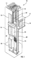
- FIG. 1 is a perspective view of an elevator system 101 including an elevator car 103, a counterweight 105, a tension member 107, a guide rail 109, a machine 111, a position reference system 113, and a controller 115.
- the elevator car 103 and counterweight 105 are connected to each other by the tension member 107.
- the tension member 107 may include or be configured as, for example, ropes, steel cables, and/or coated-steel belts.
- the counterweight 105 is configured to balance a load of the elevator car 103 and is configured to facilitate movement of the elevator car 103 concurrently and in an opposite direction with respect to the counterweight 105 within an elevator shaft 117 and along the guide rail 109.
- the tension member 107 engages the machine 111, which is part of an overhead structure of the elevator system 101.
- the machine 111 is configured to control movement between the elevator car 103 and the counterweight 105.
- the position reference system 113 may be mounted on a fixed part at the top of the elevator shaft 117, such as on a support or guide rail, and may be configured to provide position signals related to a position of the elevator car 103 within the elevator shaft 117. In other embodiments, the position reference system 113 may be directly mounted to a moving component of the machine 111, or may be located in other positions and/or configurations as known in the art.
- the position reference system 113 can be any device or mechanism for monitoring a position of an elevator car and/or counter weight, as known in the art.
- the position reference system 113 can be an encoder, sensor, or other system and can include velocity sensing, absolute position sensing, etc., as will be appreciated by those of skill in the art.
- the controller 115 is located, as shown, in a controller room 121 of the elevator shaft 117 and is configured to control the operation of the elevator system 101, and particularly the elevator car 103.
- the controller 115 may provide drive signals to the machine 111 to control the acceleration, deceleration, leveling, stopping, etc. of the elevator car 103.
- the controller 115 may also be configured to receive position signals from the position reference system 113 or any other desired position reference device.
- the elevator car 103 may stop at one or more landings 125 as controlled by the controller 115.
- the controller 115 can be located and/or configured in other locations or positions within the elevator system 101. In one embodiment, the controller may be located remotely or in the cloud.
- the machine 111 may include a motor or similar driving mechanism.
- the machine 111 is configured to include an electrically driven motor.
- the power supply for the motor may be any power source, including a power grid, which, in combination with other components, is supplied to the motor.
- the machine 111 may include a traction sheave that imparts force to tension member 107 to move the elevator car 103 within elevator shaft 117.
- FIG. 1 is merely a non-limiting example presented for illustrative and explanatory purposes.
- the system comprises a conveyance system that moves passengers between floors and/or along a single floor.
- conveyance systems may include escalators, people movers, etc.
- embodiments described herein are not limited to elevator systems, such as that shown in Figure 1 .
- embodiments disclosed herein may be applicable conveyance systems such as an elevator system 101 and a conveyance apparatus of the conveyance system such as an elevator car 103 of the elevator system 101.
- embodiments disclosed herein may be applicable conveyance systems such as an escalator system and a conveyance apparatus of the conveyance system such as a moving stair of the escalator system.
- the wireless power transfer system 200 may include a power source 210, an AC/DC power converter 220, a power management system 230, a wireless electrical power transmitter 240, a wireless electrical power transceiver 250, an energy storage device management system 260, and an energy storage device 270.
- An energy storage device 270 may not be required if energy harvesting is used.
- the wireless power transfer system 200 is configured to power first elevator car 103a of a first elevator system 101 in a first elevator shaft 117a and a second elevator car 103b of a second elevator system 101b in a second elevator shaft 117b adjacent to the first elevator shaft 117a.
- the power source 210 may be a stationary power source, such as, for example electrical grid power, wind power, solar power, generator power, etc.
- the power source 210 may provide electrical power using alternating current (AC).
- the AC electrical power provided by the power source 210 may be three phase AC for higher power greater than about 3kW.
- the AC/DC power converter 220 is configured to receive the AC electrical power from the power source 210 and convert the AC electrical power into DC electrical power.
- the AC/DC power converter 220 is electrically connected to the power source 210.
- the electrical connection between the AC/DC power converter 220 and the power source 210 may be hardwired.
- the power management system 230 is electrically connected to the AC/DC power converter 220.
- the electrical connection between the power management system 230 and the AC/DC power converter 220 may be hardwired.
- the power management system 230 operates as a power controller to supply the power needs of the elevator car 103 proximate a second location A2 and a first location A1.
- the first location A1 may be a plane through the elevator shafts 117a, 117b about perpendicular to an axis X1 that runs parallel to the elevator shaft 117a, 117b.
- the power management system 230 controls switching, directing, or redirecting power to the elevator cars 103a, 103b, through a single wireless power transmitters 240 as needed to satisfy the power requirements of the elevator car 103.
- the bus control switching device 232 may include, but not be limited to, electromechanical and solid state semiconductor switching devices including relays, contactors, solid state contactors as well as semiconductor switching devices such as transistors, FETs, MOSFETS, IGBT's, thyristors, SCR's, and the like.
- the voltages and frequencies of the power supplied by the power source 210 may be adjusted by the bus control switching device 232.
- the wireless power transmitters 240 may later adjust the frequency of the electrical power to satisfy the needs of the elevator car 103.
- the wireless electrical power transmitter 240 may be intelligent enough to identify the resonant frequency and power flow between and adjust frequencies to meet requested power flow. The intelligence could also be with the wireless electrical power transmitter 240 in the sensing of the current being transmitted.
- the wireless power transfer system 200 may include one or more wireless electrical power transmitters 240, as shown in FIG. 2 .
- the electrical power transmitters 240 are electrically connected to the power management system 230.
- the electrical connection between the electrical power transmitter 240 and the power management system 230 may be hardwired.
- the wireless electrical power transmitter 240 may be located at a first locations A1 along a wall 118a of the first elevator shaft 117a and a wall 118b of the second elevator shaft 117.
- the wall 118a of the first elevator shaft 117a is adjacent to the wall 118b of the second elevator shaft 117b, as shown in FIGs. 2 and 3 .
- the wireless electrical power transmitter 240 may be attached to the walls 118a, 118b, embedded in the walls 118a, 118b, within the walls 118a, 118b, or in any other desired arrangement.
- the wireless electrical power transmitter 240 may include one or more electric coils 244, 246 and each electric coil 244, 246 may have a selected number of electrical coil windings configured to generate a magnetic field 242 when electrical power is run through the electrical coil 244, 246.
- the wireless electrical power transmitter 240 may be attached to a rotational device 280 and the electrical power transmitter 240 may include only a single first electrical coil 244, as shown in FIG. 3 .
- the rotational device 280 is configured to rotate the first electrical coil 244 towards the wall 118a of the first elevator shaft 117a and then towards the wall 118b of the second elevator shaft 117b, thus allowing the first electrical coil 244 to wirelessly transmit electrical power to the wireless electrical power transceiver 250 of the elevator car 103a of the first elevator system 101a or the elevator car 103b of the second elevator system 101b.
- the rotational device 280 may be an electrical motor, hydraulic actuator, conveyer belt, or similar device known to one of skill in the art capable of rotating the wireless electrical power transmitter 240.
- the rotational device 280 has rotated the wireless electrical power transmitter 240 towards the wall 118b of the second elevator shaft 117b as the elevator car 103a of the second elevator system 101 is located at the second location A2 awaiting wireless electrical power from the wireless electrical power transmitter 240.
- the rotational device 280 may allow the wireless electrical power transmitter 240 to wirelessly transmit electrical power to any number of elevator systems 101.
- the wireless electrical power transmitter 240 may be located in the middle of where four corners of four elevator systems 101 meet and thus the rotational device 280 may move (e.g., rotate or translate) the first electrical coil 244 to each of the four corners of four elevator systems 101 to wirelessly transfer power to a wireless electrical power transceiver 250 within each of the four elevator system 101.
- the wireless electrical power transmitter 240 includes a dedicated electrical coil 244, 246 for each elevator system 101a, 101b being served, as shown in FIG. 2 rather than the shared electrical coil (e.g., the first electrical coil 244) of FIG. 3 .
- the wireless electrical power transmitter 240 includes a first electrical coil 244 adjacent to the wall 118a of the first elevator system 100a and a second electrical coil 246 adjacent to the wall 118b of the second elevator system 100b.
- the wireless electrical power transmitter 240 may include any number of electrical coils 244 to wirelessly transmit electrical power to any number of elevator systems 101.
- the wireless electrical power transmitter 240 may be located in the middle of where four corners of four elevator systems 101 meet and thus the wireless electrical power transmitter 240 may include four electric coils aligned to each of the four corners of four elevator systems 101 to wirelessly transfer power to a wireless electrical power transceiver 250 within each of the four elevator system 101.
- the elevator car 103a, 103b, of each elevator system 101a, 101b may include a wireless electrical power transceiver 250, as shown in FIG. 2 .
- the wireless electrical wireless electrical power transceiver 250 may be located at different locations along a surface 104a, 104b of the elevator car 103a, 103b.
- the wireless electrical power transceivers 250 may be attached to the surface 104a, 104b of the elevator car 103a, 103b or embedded in the surface 104a, 104b of the elevator car 103a, 103b.
- the surface 104a, 104b of the elevator car 103a, 103b is located opposite the wall 118a, 118b of the elevator shaft 117a, 117b where the wireless electrical power transmitter 240 is located.
- the wireless electrical power transceivers 250 and the wireless electrical power transmitter 240 at the second location A2 are in a facing spaced relationship and a gap G1 is formed therebetween.
- the gap G1 is formed between the wireless electrical power transceivers 250 of each elevator car 103a, 103b and the wireless electrical power transmitter 240 at the second location A2, as shown in FIG. 2 .
- the gap G1 will also be present between the wireless electrical power transceivers 250 and the wireless electrical power transmitter 240, when the wireless electrical power transmitter 240 is rotated in FIG. 3 at the second location A2.
- the wireless electrical power transceivers 250 may include an electric coil 252 having a selected number of electrical coil windings configured to generate an electrical power in response to the magnetic field 242 when the wireless electrical power transceiver 250 is within the transmission range of the magnetic field 242 generated by the wireless electrical power transmitter 240.
- the electrical power transceiver 250 is electrically connected to the energy storage device management system 260.
- the electrical connection between the electrical power transceiver 250 and the energy storage device management system 260 may be hardwired.
- the energy storage device management system 260 is configured to condition the electrical power received from the electrical power transceivers 250 and transfer the electrical power to the energy storage device 270 as needed.
- the energy storage device management system 154 monitors operation data of the energy storage device 270 including but not limited to the state of charge of the energy storage device 270, a state of health of the energy storage device 270, and a temperature of the energy storage device 270.
- Examples of the energy storage device 270 may include a battery system (e.g., a battery or bank of batteries), fuel cells, flow battery, and others devices capable of storing and outputting electric energy that may be DC.
- the energy storage device 270 may store potential energy rather than electrical energy and that potential energy may be utilized to create electrical energy for the elevator car 103a, 130b.
- the energy storage device 270 may include a battery system, which may employ multiple batteries organized into battery banks.
- the energy storage device 270 is electrically connected to the elevator car 103a, 103b.
- the electrical connection between the energy storage device 270 and the elevator car 103a, 103b may be hardwired.
- the energy storage device 270 may power lighting inside the elevator car 103, fans, an emergency phone, climate controls, communication system, and/or the operating panel of the elevator car 103.
- the operating panel of the elevator car 103 may consists of floor buttons, a door open button, a door close button, other similar buttons, or may be a touchscreen.
- the wireless electrical power transceiver 250 may also enable the transfer of electrical power from the elevator car 103a of the first elevator system 101a to the elevator car 103b of the second elevator system 101b.
- the wireless electrical power transceivers 250 may include one or more electric coils 252 and each electric coil 252 may have a selected number of electrical coil windings configured to generate a magnetic field 248 when electrical power is run through the electrical coil 252 from the energy storage device 270.
- the wireless electrical power transceiver 250 of the first elevator system 101a may run electrical power through its electric coils 252 to generate a magnetic field 248 and transfer electrical power to the wireless electrical power transceiver 250 of the second elevator system 101b when each elevator car 103a, 103b is located at the first location A1.
- the magnetic field 248 generated by the electric coil 252 of the first elevator system 101a induces current to flow in the electric coil 252 of the second elevator system 101b, thus generating electrical power in response to the magnetic field 248.
- the wireless electrical power transceiver 250 may also enable the transfer of electrical power from the elevator car 103b of the second elevator system 101b to the elevator car 103a of the first elevator system 101a.
- the wireless electrical power transceivers 250 may include one or more electric coils 252 and each electric coil 252 may have a selected number of electrical coil windings configured to generate a magnetic field 248 when electrical power is run through the electrical coil 252 from the energy storage device 270.
- the wireless electrical power transceiver 250 of the second elevator system 101b may run electrical power through its electric coils 252 to generate a magnetic field 248 and transfer electrical power to the wireless electrical power transceiver 250 of the first elevator system 101a when each elevator car 103a, 103b is located at the first location A1.
- the magnetic field 248 generated by the electric coil 252 of the second elevator system 101b induces current to flow in the electric coil 252 of the first elevator system 101a, thus generating electrical power in response to the magnetic field 248.
- FIGs. 2-5 show the wireless transfer of electrical power between two elevator cars, any number of elevator cars may be used with embodiments disclosed herein.
- one elevator car may transfer wireless electrical power to three elevator cars if the elevator cars are organized in a square and the wireless electrical power transceiver 250 of each elevator car is located proximate the center of the square.
Landscapes
- Engineering & Computer Science (AREA)
- Computer Networks & Wireless Communication (AREA)
- Power Engineering (AREA)
- Civil Engineering (AREA)
- Mechanical Engineering (AREA)
- Structural Engineering (AREA)
- Elevator Control (AREA)
- Indicating And Signalling Devices For Elevators (AREA)
- Electric Propulsion And Braking For Vehicles (AREA)
Abstract
Description
- The embodiments herein relate to the field of conveyance systems, and specifically to a method and apparatus for powering a conveyance system.
- Conveyance systems, such as, for example, elevator systems, escalator systems, and moving walkways require electrical power for operation. Travelling cables typically connect an elevator car of the elevator system to a stationary power source to provide power to the elevator car. Travelling cables add expense, weight, and complexity to elevator car operation and installation, thus improved methods of powering elevator cars are desired.
- According to an embodiment, a wireless power transfer system for wirelessly powering a conveyance apparatus of a first conveyance system and a conveyance apparatus of a second conveyance system is provided. The wireless power transfer system including: a wireless electrical power transceiver located along a surface of the conveyance apparatus of the first conveyance system, a wireless electrical power transceiver located along a surface of the conveyance apparatus of the second conveyance system, the surface of the conveyance apparatus of the second conveyance system being opposite of the surface of the conveyance apparatus of the first conveyance system, wherein the wireless electrical power transceiver of the first conveyance system is configured to wirelessly transfer electrical power to the wireless electrical power transceiver of the second conveyance system when the wireless electrical power transceiver of the first conveyance system and the wireless electrical power transceiver of the second conveyance system are located proximate to one another.
- In addition to one or more of the features described herein, or as an alternative, further embodiments may include that the wireless electrical power transceiver of the first conveyance system and the wireless electrical power transceiver of the second conveyance system are in a facing spaced relationship when the wireless electrical power transceiver of the first conveyance system and the wireless electrical power transceiver of the second conveyance system are located at a first location.
- In addition to one or more of the features described herein, or as an alternative, further embodiments may include that the first conveyance system is a first elevator system and the conveyance apparatus of the first conveyance system is an elevator car, and wherein the second conveyance system is a second elevator system and the conveyance apparatus of the second conveyance system is an elevator car.
- In addition to one or more of the features described herein, or as an alternative, further embodiments may include: a wireless electrical power transmitter located in a second location along the first conveyance system opposite the surface of the conveyance apparatus of the first conveyance system and along the second conveyance system opposite the surface of the conveyance apparatus of the second conveyance system; wherein the wireless electrical power transmitter is configured to wirelessly transmit electrical power to the wireless electrical power transceiver of the first conveyance system when the wireless electrical power transceiver of the first conveyance system is located in the second location.
- In addition to one or more of the features described herein, or as an alternative, further embodiments may include: a wireless electrical power transmitter located in a second location along the first conveyance system opposite the surface of the conveyance apparatus of the first conveyance system and along the second conveyance system opposite the surface of the conveyance apparatus of the second conveyance system, wherein the wireless electrical power transmitter is configured to wirelessly transmit electrical power to the wireless electrical power transceiver of the second conveyance system when the wireless electrical power transceiver of the second conveyance system is located in the first location.
- In addition to one or more of the features described herein, or as an alternative, further embodiments may include: a first electrical coil of the wireless electrical power transmitter adjacent to the wall of the first conveyance system; and a rotational device configured to rotate the wireless electrical power transmitter and the first electrical coil towards the wireless electrical power transceiver of the first conveyance system or wireless electrical power transceiver of the second conveyance system.
- In addition to one or more of the features described herein, or as an alternative, further embodiments may include: a first electrical coil of the wireless electrical power transmitter adjacent to the wall of the first conveyance system; and a second electrical coil of the wireless electrical power transmitter adjacent to the wall of the second conveyance system.
- In addition to one or more of the features described herein, or as an alternative, further embodiments may include that the wireless electrical power transceiver of the first conveyance system and the wireless electrical power transmitter are in a facing spaced relationship defining a gap therebetween when the wireless electrical power transceiver is located at a second location.
- In addition to one or more of the features described herein, or as an alternative, further embodiments may include that the wireless electrical power transceiver of the second conveyance system and the wireless electrical power transmitter are in a facing spaced relationship defining a gap therebetween when the wireless electrical power transceiver is located at a second location.
- In addition to one or more of the features described herein, or as an alternative, further embodiments may include that the first elevator system includes an elevator shaft, and wherein the second elevator system includes an elevator shaft adjacent to the elevator shaft of the first elevator system.
- According to a system including a first conveyance system and a second conveyance system is provided. The system including: a conveyance apparatus of the first conveyance system; a conveyance apparatus of the second conveyance system; and a wireless power transfer system for wirelessly powering the conveyance apparatus of the first conveyance system and the conveyance apparatus of the second conveyance system, the wireless power transfer system including: a wireless electrical power transceiver located along a surface of the conveyance apparatus of the first conveyance system, a wireless electrical power transceiver located along a surface of the conveyance apparatus of the second conveyance system, surface of the conveyance apparatus of the second conveyance system being opposite of the surface of the conveyance apparatus of the first conveyance system, wherein the wireless electrical power transceiver of the first conveyance system is configured to wirelessly transfer electrical power to the wireless electrical power transceiver of the second conveyance system when the wireless electrical power transceiver of the first conveyance system and the wireless electrical power transceiver of the second conveyance system are located at a first location.
- In addition to one or more of the features described herein, or as an alternative, further embodiments may include that the wireless electrical power transceiver of the first conveyance system and the wireless electrical power transceiver of the second conveyance system are in a facing spaced relationship when the wireless electrical power transceiver of the first conveyance system and the wireless electrical power transceiver of the second conveyance system are located at a first location.
- In addition to one or more of the features described herein, or as an alternative, further embodiments may include that the first conveyance system is a first elevator system and the conveyance apparatus of the first conveyance system is an elevator car, and wherein the second conveyance system is a second elevator system and the conveyance apparatus of the second conveyance system is an elevator car.
- In addition to one or more of the features described herein, or as an alternative, further embodiments may include that the wireless power transfer system further includes: a wireless electrical power transmitter located in a second location along the first conveyance system opposite the surface of the conveyance apparatus of the first conveyance system and along the second conveyance system opposite the surface of the conveyance apparatus of the second conveyance system; wherein the wireless electrical power transmitter is configured to wirelessly transmit electrical power to the wireless electrical power transceiver of the first conveyance system when the wireless electrical power transceiver of the first conveyance system is located in the second location, and wherein the wireless electrical power transmitter is configured to wirelessly transmit electrical power to the wireless electrical power transceiver of the second conveyance system when the wireless electrical power transceiver of the second conveyance system is located in the first location.
- In addition to one or more of the features described herein, or as an alternative, further embodiments may include that the wireless power transfer system further includes: a first electrical coil of the wireless electrical power transmitter adjacent to the wall of the first conveyance system; and a rotational device configured to rotate the wireless electrical power transmitter and the first electrical coil towards the wireless electrical power transceiver of the first conveyance system or wireless electrical power transceiver of the second conveyance system.
- In addition to one or more of the features described herein, or as an alternative, further embodiments may include that the wireless power transfer system further includes: a first electrical coil of the wireless electrical power transmitter adjacent to the wall of the first conveyance system; and a second electrical coil of the wireless electrical power transmitter adjacent to the wall of the second conveyance system.
- In addition to one or more of the features described herein, or as an alternative, further embodiments may include that the wireless electrical power transceiver of the first conveyance system and the wireless electrical power transmitter are in a facing spaced relationship defining a gap therebetween when the wireless electrical power transceiver is located at a second location.
- In addition to one or more of the features described herein, or as an alternative, further embodiments may include that the wireless electrical power transceiver of the second conveyance system and the wireless electrical power transmitter are in a facing spaced relationship defining a gap therebetween when the wireless electrical power transceiver is located at a second location.
- In addition to one or more of the features described herein, or as an alternative, further embodiments may include that the first elevator system includes an elevator shaft, and wherein the second elevator system includes an elevator shaft adjacent to the elevator shaft of the first elevator system.
- According to another embodiment, a wireless power transfer system for wirelessly powering an elevator car of a first elevator shaft and an elevator car of a second elevator shaft is provided. The wireless power transfer system including: a wireless electrical power transceiver located along a surface of the elevator car of the first elevator shaft, a wireless electrical power transceiver located along a surface of the elevator car of the second elevator shaft, the surface of the elevator car of the second elevator shaft being opposite of the surface of the elevator car of the first elevator shaft, wherein the wireless electrical power transceiver of the first elevator shaft is configured to wirelessly transfer electrical power to the wireless electrical power transceiver of the second elevator shaft when the wireless electrical power transceiver of the first elevator shaft and the wireless electrical power transceiver of the second elevator shaft are located proximate to one another.
- Technical effects of embodiments of the present disclosure include powering elevator cars of multiple different shafts of an elevator system wirelessly using a wireless power transceiver on another elevator.
- The foregoing features and elements may be combined in various combinations without exclusivity, unless expressly indicated otherwise. These features and elements as well as the operation thereof will become more apparent in light of the following description and the accompanying drawings. It should be understood, however, that the following description and drawings are intended to be illustrative and explanatory in nature and non-limiting.
- The present disclosure is illustrated by way of example and not limited in the accompanying figures in which like reference numerals indicate similar elements.
-
FIG. 1 is a schematic illustration of an elevator system that may employ various embodiments of the present disclosure; -
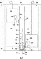
FIG. 2 is a schematic illustration of a wireless power transfer system for the elevator system ofFIG. 1 , in accordance with an embodiment of the disclosure; -
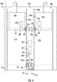
FIG. 3 is a schematic illustration of a wireless power transfer system for the elevator system ofFIG. 1 , in accordance with an embodiment of the disclosure; -
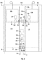
FIG. 4 is a schematic illustration of a wireless power transfer system for the elevator system ofFIG. 1 , in accordance with an embodiment of the disclosure; and -
FIG. 5 is a schematic illustration of a wireless power transfer system for the elevator system ofFIG. 1 , in accordance with an embodiment of the disclosure. -
FIG. 1 is a perspective view of anelevator system 101 including anelevator car 103, acounterweight 105, atension member 107, aguide rail 109, amachine 111, aposition reference system 113, and acontroller 115. Theelevator car 103 andcounterweight 105 are connected to each other by thetension member 107. Thetension member 107 may include or be configured as, for example, ropes, steel cables, and/or coated-steel belts. Thecounterweight 105 is configured to balance a load of theelevator car 103 and is configured to facilitate movement of theelevator car 103 concurrently and in an opposite direction with respect to thecounterweight 105 within anelevator shaft 117 and along theguide rail 109. - The
tension member 107 engages themachine 111, which is part of an overhead structure of theelevator system 101. Themachine 111 is configured to control movement between theelevator car 103 and thecounterweight 105. Theposition reference system 113 may be mounted on a fixed part at the top of theelevator shaft 117, such as on a support or guide rail, and may be configured to provide position signals related to a position of theelevator car 103 within theelevator shaft 117. In other embodiments, theposition reference system 113 may be directly mounted to a moving component of themachine 111, or may be located in other positions and/or configurations as known in the art. Theposition reference system 113 can be any device or mechanism for monitoring a position of an elevator car and/or counter weight, as known in the art. For example, without limitation, theposition reference system 113 can be an encoder, sensor, or other system and can include velocity sensing, absolute position sensing, etc., as will be appreciated by those of skill in the art. - The
controller 115 is located, as shown, in acontroller room 121 of theelevator shaft 117 and is configured to control the operation of theelevator system 101, and particularly theelevator car 103. For example, thecontroller 115 may provide drive signals to themachine 111 to control the acceleration, deceleration, leveling, stopping, etc. of theelevator car 103. Thecontroller 115 may also be configured to receive position signals from theposition reference system 113 or any other desired position reference device. When moving up or down within theelevator shaft 117 alongguide rail 109, theelevator car 103 may stop at one ormore landings 125 as controlled by thecontroller 115. Although shown in acontroller room 121, those of skill in the art will appreciate that thecontroller 115 can be located and/or configured in other locations or positions within theelevator system 101. In one embodiment, the controller may be located remotely or in the cloud. - The
machine 111 may include a motor or similar driving mechanism. In accordance with embodiments of the disclosure, themachine 111 is configured to include an electrically driven motor. The power supply for the motor may be any power source, including a power grid, which, in combination with other components, is supplied to the motor. Themachine 111 may include a traction sheave that imparts force totension member 107 to move theelevator car 103 withinelevator shaft 117. - Although shown and described with a roping system including
tension member 107, elevator systems that employ other methods and mechanisms of moving an elevator car within an elevator shaft may employ embodiments of the present disclosure. For example, embodiments may be employed in ropeless elevator systems using a linear motor to impart motion to an elevator car. Embodiments may also be employed in ropeless elevator systems using a hydraulic lift to impart motion to an elevator car.FIG. 1 is merely a non-limiting example presented for illustrative and explanatory purposes. - In other embodiments, the system comprises a conveyance system that moves passengers between floors and/or along a single floor. Such conveyance systems may include escalators, people movers, etc. Accordingly, embodiments described herein are not limited to elevator systems, such as that shown in
Figure 1 . In one example, embodiments disclosed herein may be applicable conveyance systems such as anelevator system 101 and a conveyance apparatus of the conveyance system such as anelevator car 103 of theelevator system 101. In another example, embodiments disclosed herein may be applicable conveyance systems such as an escalator system and a conveyance apparatus of the conveyance system such as a moving stair of the escalator system. - Referring now to
FIGs. 2-4 with continued reference toFIG. 1 , a view of a wirelesspower transfer system 200 for use with one ormore elevator systems 101 ofFIG. 1 is illustrated, in accordance with an embodiment of the present disclosure. It should be appreciated that, although particular systems are separately defined in the schematic block diagrams, each or any of the systems may be otherwise combined or separated via hardware and/or software. The wirelesspower transfer system 200 may include apower source 210, an AC/DC power converter 220, apower management system 230, a wirelesselectrical power transmitter 240, a wirelesselectrical power transceiver 250, an energy storagedevice management system 260, and anenergy storage device 270. Anenergy storage device 270 may not be required if energy harvesting is used. The wirelesspower transfer system 200 is configured to powerfirst elevator car 103a of afirst elevator system 101 in afirst elevator shaft 117a and asecond elevator car 103b of asecond elevator system 101b in asecond elevator shaft 117b adjacent to thefirst elevator shaft 117a. - The
power source 210 may be a stationary power source, such as, for example electrical grid power, wind power, solar power, generator power, etc. Thepower source 210 may provide electrical power using alternating current (AC). The AC electrical power provided by thepower source 210 may be three phase AC for higher power greater than about 3kW. The AC/DC power converter 220 is configured to receive the AC electrical power from thepower source 210 and convert the AC electrical power into DC electrical power. The AC/DC power converter 220 is electrically connected to thepower source 210. The electrical connection between the AC/DC power converter 220 and thepower source 210 may be hardwired. - The
power management system 230 is electrically connected to the AC/DC power converter 220. The electrical connection between thepower management system 230 and the AC/DC power converter 220 may be hardwired. Thepower management system 230 operates as a power controller to supply the power needs of theelevator car 103 proximate a second location A2 and a first location A1. The first location A1 may be a plane through theelevator shafts elevator shaft power management system 230 controls switching, directing, or redirecting power to theelevator cars wireless power transmitters 240 as needed to satisfy the power requirements of theelevator car 103. Switching, directing, and redirecting may readily be accomplished employing a buscontrol switching device 232 of thepower management system 230. The buscontrol switching device 232 may include, but not be limited to, electromechanical and solid state semiconductor switching devices including relays, contactors, solid state contactors as well as semiconductor switching devices such as transistors, FETs, MOSFETS, IGBT's, thyristors, SCR's, and the like. In addition, to facilitate and implement the functionality of thepower management system 230, the voltages and frequencies of the power supplied by thepower source 210 may be adjusted by the buscontrol switching device 232. Thewireless power transmitters 240 may later adjust the frequency of the electrical power to satisfy the needs of theelevator car 103. The wirelesselectrical power transmitter 240 may be intelligent enough to identify the resonant frequency and power flow between and adjust frequencies to meet requested power flow. The intelligence could also be with the wirelesselectrical power transmitter 240 in the sensing of the current being transmitted. - The wireless
power transfer system 200 may include one or more wirelesselectrical power transmitters 240, as shown inFIG. 2 . Theelectrical power transmitters 240 are electrically connected to thepower management system 230. The electrical connection between theelectrical power transmitter 240 and thepower management system 230 may be hardwired. The wirelesselectrical power transmitter 240 may be located at a first locations A1 along awall 118a of thefirst elevator shaft 117a and awall 118b of thesecond elevator shaft 117. Thewall 118a of thefirst elevator shaft 117a is adjacent to thewall 118b of thesecond elevator shaft 117b, as shown inFIGs. 2 and3 . The wirelesselectrical power transmitter 240 may be attached to thewalls walls walls - The wireless
electrical power transmitter 240 may include one or moreelectric coils electric coil magnetic field 242 when electrical power is run through theelectrical coil - In an embodiment, the wireless
electrical power transmitter 240 may be attached to arotational device 280 and theelectrical power transmitter 240 may include only a single firstelectrical coil 244, as shown inFIG. 3 . Therotational device 280 is configured to rotate the firstelectrical coil 244 towards thewall 118a of thefirst elevator shaft 117a and then towards thewall 118b of thesecond elevator shaft 117b, thus allowing the firstelectrical coil 244 to wirelessly transmit electrical power to the wirelesselectrical power transceiver 250 of theelevator car 103a of thefirst elevator system 101a or theelevator car 103b of thesecond elevator system 101b. Therotational device 280 may be an electrical motor, hydraulic actuator, conveyer belt, or similar device known to one of skill in the art capable of rotating the wirelesselectrical power transmitter 240. In the example shown inFIG. 3 , therotational device 280 has rotated the wirelesselectrical power transmitter 240 towards thewall 118b of thesecond elevator shaft 117b as theelevator car 103a of thesecond elevator system 101 is located at the second location A2 awaiting wireless electrical power from the wirelesselectrical power transmitter 240. - It is understood that while only two
elevator systems FIG. 3 . Therotational device 280 may allow the wirelesselectrical power transmitter 240 to wirelessly transmit electrical power to any number ofelevator systems 101. For example, the wirelesselectrical power transmitter 240 may be located in the middle of where four corners of fourelevator systems 101 meet and thus therotational device 280 may move (e.g., rotate or translate) the firstelectrical coil 244 to each of the four corners of fourelevator systems 101 to wirelessly transfer power to a wirelesselectrical power transceiver 250 within each of the fourelevator system 101. - In another embodiment, the wireless
electrical power transmitter 240 includes a dedicatedelectrical coil elevator system FIG. 2 rather than the shared electrical coil (e.g., the first electrical coil 244) ofFIG. 3 . In the example shown inFIG. 2 , the wirelesselectrical power transmitter 240 includes a firstelectrical coil 244 adjacent to thewall 118a of the first elevator system 100a and a secondelectrical coil 246 adjacent to thewall 118b of the second elevator system 100b. - It is understood that while only two
elevator systems FIG. 2 . The wirelesselectrical power transmitter 240 may include any number ofelectrical coils 244 to wirelessly transmit electrical power to any number ofelevator systems 101. For example, the wirelesselectrical power transmitter 240 may be located in the middle of where four corners of fourelevator systems 101 meet and thus the wirelesselectrical power transmitter 240 may include four electric coils aligned to each of the four corners of fourelevator systems 101 to wirelessly transfer power to a wirelesselectrical power transceiver 250 within each of the fourelevator system 101. - The
elevator car elevator system electrical power transceiver 250, as shown inFIG. 2 . The wireless electrical wirelesselectrical power transceiver 250 may be located at different locations along asurface elevator car electrical power transceivers 250 may be attached to thesurface elevator car surface elevator car surface elevator car wall elevator shaft electrical power transmitter 240 is located. Therefore, when theelevator car electrical power transceivers 250 are located at the second location A2, the wirelesselectrical power transceivers 250 and the wirelesselectrical power transmitter 240 at the second location A2 are in a facing spaced relationship and a gap G1 is formed therebetween. The gap G1 is formed between the wirelesselectrical power transceivers 250 of eachelevator car electrical power transmitter 240 at the second location A2, as shown inFIG. 2 . The gap G1 will also be present between the wirelesselectrical power transceivers 250 and the wirelesselectrical power transmitter 240, when the wirelesselectrical power transmitter 240 is rotated inFIG. 3 at the second location A2. The wirelesselectrical power transceivers 250 may include anelectric coil 252 having a selected number of electrical coil windings configured to generate an electrical power in response to themagnetic field 242 when the wirelesselectrical power transceiver 250 is within the transmission range of themagnetic field 242 generated by the wirelesselectrical power transmitter 240. - The
electrical power transceiver 250 is electrically connected to the energy storagedevice management system 260. The electrical connection between theelectrical power transceiver 250 and the energy storagedevice management system 260 may be hardwired. The energy storagedevice management system 260 is configured to condition the electrical power received from theelectrical power transceivers 250 and transfer the electrical power to theenergy storage device 270 as needed. The energy storage device management system 154 monitors operation data of theenergy storage device 270 including but not limited to the state of charge of theenergy storage device 270, a state of health of theenergy storage device 270, and a temperature of theenergy storage device 270. Examples of theenergy storage device 270 may include a battery system (e.g., a battery or bank of batteries), fuel cells, flow battery, and others devices capable of storing and outputting electric energy that may be DC. In one embodiment, theenergy storage device 270 may store potential energy rather than electrical energy and that potential energy may be utilized to create electrical energy for theelevator car 103a, 130b. Theenergy storage device 270 may include a battery system, which may employ multiple batteries organized into battery banks. Theenergy storage device 270 is electrically connected to theelevator car energy storage device 270 and theelevator car energy storage device 270 may power lighting inside theelevator car 103, fans, an emergency phone, climate controls, communication system, and/or the operating panel of theelevator car 103. The operating panel of theelevator car 103 may consists of floor buttons, a door open button, a door close button, other similar buttons, or may be a touchscreen. - As shown in
FIG. 4 , the wirelesselectrical power transceiver 250 may also enable the transfer of electrical power from theelevator car 103a of thefirst elevator system 101a to theelevator car 103b of thesecond elevator system 101b. The wirelesselectrical power transceivers 250 may include one or moreelectric coils 252 and eachelectric coil 252 may have a selected number of electrical coil windings configured to generate amagnetic field 248 when electrical power is run through theelectrical coil 252 from theenergy storage device 270. The wirelesselectrical power transceiver 250 of thefirst elevator system 101a may run electrical power through itselectric coils 252 to generate amagnetic field 248 and transfer electrical power to the wirelesselectrical power transceiver 250 of thesecond elevator system 101b when eachelevator car magnetic field 248 generated by theelectric coil 252 of thefirst elevator system 101a induces current to flow in theelectric coil 252 of thesecond elevator system 101b, thus generating electrical power in response to themagnetic field 248. - As shown in
FIG. 5 , the wirelesselectrical power transceiver 250 may also enable the transfer of electrical power from theelevator car 103b of thesecond elevator system 101b to theelevator car 103a of thefirst elevator system 101a. The wirelesselectrical power transceivers 250 may include one or moreelectric coils 252 and eachelectric coil 252 may have a selected number of electrical coil windings configured to generate amagnetic field 248 when electrical power is run through theelectrical coil 252 from theenergy storage device 270. The wirelesselectrical power transceiver 250 of thesecond elevator system 101b may run electrical power through itselectric coils 252 to generate amagnetic field 248 and transfer electrical power to the wirelesselectrical power transceiver 250 of thefirst elevator system 101a when eachelevator car magnetic field 248 generated by theelectric coil 252 of thesecond elevator system 101b induces current to flow in theelectric coil 252 of thefirst elevator system 101a, thus generating electrical power in response to themagnetic field 248. It is understood that while the examples illustrated inFIGs. 2-5 show the wireless transfer of electrical power between two elevator cars, any number of elevator cars may be used with embodiments disclosed herein. In one non-limiting example, one elevator car may transfer wireless electrical power to three elevator cars if the elevator cars are organized in a square and the wirelesselectrical power transceiver 250 of each elevator car is located proximate the center of the square. - The term "about" is intended to include the degree of error associated with measurement of the particular quantity and/or manufacturing tolerances based upon the equipment available at the time of filing the application.
- The terminology used herein is for the purpose of describing particular embodiments only and is not intended to be limiting of the present disclosure. As used herein, the singular forms "a", "an" and "the" are intended to include the plural forms as well, unless the context clearly indicates otherwise. It will be further understood that the terms "comprises" and/or "comprising," when used in this specification, specify the presence of stated features, integers, steps, operations, elements, and/or components, but do not preclude the presence or addition of one or more other features, integers, steps, operations, element components, and/or groups thereof.
- Those of skill in the art will appreciate that various example embodiments are shown and described herein, each having certain features in the particular embodiments, but the present disclosure is not thus limited. Rather, the present disclosure can be modified to incorporate any number of variations, alterations, substitutions, combinations, sub-combinations, or equivalent arrangements not heretofore described, but which are commensurate with the scope of the present disclosure. Additionally, while various embodiments of the present disclosure have been described, it is to be understood that aspects of the present disclosure may include only some of the described embodiments. Accordingly, the present disclosure is not to be seen as limited by the foregoing description, but is only limited by the scope of the appended claims.
Claims (15)
- A wireless power transfer system for wirelessly powering a conveyance apparatus of a first conveyance system and a conveyance apparatus of a second conveyance system, the wireless power transfer system comprising:a wireless electrical power transceiver located along a surface of the conveyance apparatus of the first conveyance system,a wireless electrical power transceiver located along a surface of the conveyance apparatus of the second conveyance system, the surface of the conveyance apparatus of the second conveyance system being opposite of the surface of the conveyance apparatus of the first conveyance system,wherein the wireless electrical power transceiver of the first conveyance system is configured to wirelessly transfer electrical power to the wireless electrical power transceiver of the second conveyance system when the wireless electrical power transceiver of the first conveyance system and the wireless electrical power transceiver of the second conveyance system are located proximate to one another.
- The wireless power transfer system of claim 1, wherein the wireless electrical power transceiver of the first conveyance system and the wireless electrical power transceiver of the second conveyance system are in a facing spaced relationship when the wireless electrical power transceiver of the first conveyance system and the wireless electrical power transceiver of the second conveyance system are located at a first location.
- The wireless power transfer system of claim 1 or 2, wherein the first conveyance system is a first elevator system and the conveyance apparatus of the first conveyance system is an elevator car, and wherein the second conveyance system is a second elevator system and the conveyance apparatus of the second conveyance system is an elevator car.
- The wireless power transfer system of claim 3, wherein the first elevator system includes an elevator shaft, and wherein the second elevator system includes an elevator shaft adjacent to the elevator shaft of the first elevator system.
- The wireless power transfer system of any preceding claim, further comprising:a wireless electrical power transmitter located in a second location along the first conveyance system opposite the surface of the conveyance apparatus of the first conveyance system and along the second conveyance system opposite the surface of the conveyance apparatus of the second conveyance system;wherein the wireless electrical power transmitter is configured to wirelessly transmit electrical power to the wireless electrical power transceiver of the first conveyance system when the wireless electrical power transceiver of the first conveyance system is located in the second location.
- The wireless power transfer system of any preceding claim, further comprising:a wireless electrical power transmitter located in a second location along the first conveyance system opposite the surface of the conveyance apparatus of the first conveyance system and along the second conveyance system opposite the surface of the conveyance apparatus of the second conveyance system,wherein the wireless electrical power transmitter is configured to wirelessly transmit electrical power to the wireless electrical power transceiver of the second conveyance system when the wireless electrical power transceiver of the second conveyance system is located in the first location.
- The wireless power transfer system of claim 5 or 6, further comprising:a first electrical coil of the wireless electrical power transmitter adjacent to the wall of the first conveyance system; anda rotational device configured to rotate the wireless electrical power transmitter and the first electrical coil towards the wireless electrical power transceiver of the first conveyance system or wireless electrical power transceiver of the second conveyance system;optionally further comprising:
a second electrical coil of the wireless electrical power transmitter adjacent to the wall of the second conveyance system. - The wireless power transfer system of any of claims 5 to 7, wherein the wireless electrical power transceiver of the first conveyance system and the wireless electrical power transmitter are in a facing spaced relationship defining a gap therebetween when the wireless electrical power transceiver is located at a second location, and/or wherein the wireless electrical power transceiver of the second conveyance system and the wireless electrical power transmitter are in a facing spaced relationship defining a gap therebetween when the wireless electrical power transceiver is located at a second location.
- A system including a first conveyance system and a second conveyance system, the system comprising
a conveyance apparatus of the first conveyance system;
a conveyance apparatus of the second conveyance system; and
a wireless power transfer system for wirelessly powering the conveyance apparatus of the first conveyance system and the conveyance apparatus of the second conveyance system, the wireless power transfer system comprising:a wireless electrical power transceiver located along a surface of the conveyance apparatus of the first conveyance system,a wireless electrical power transceiver located along a surface of the conveyance apparatus of the second conveyance system, surface of the conveyance apparatus of the second conveyance system being opposite of the surface of the conveyance apparatus of the first conveyance system,wherein the wireless electrical power transceiver of the first conveyance system is configured to wirelessly transfer electrical power to the wireless electrical power transceiver of the second conveyance system when the wireless electrical power transceiver of the first conveyance system and the wireless electrical power transceiver of the second conveyance system are located at a first location. - The system of claim 9, wherein the wireless electrical power transceiver of the first conveyance system and the wireless electrical power transceiver of the second conveyance system are in a facing spaced relationship when the wireless electrical power transceiver of the first conveyance system and the wireless electrical power transceiver of the second conveyance system are located at a first location.
- The system of claim 9 or 10, wherein the first conveyance system is a first elevator system and the conveyance apparatus of the first conveyance system is an elevator car, and wherein the second conveyance system is a second elevator system and the conveyance apparatus of the second conveyance system is an elevator car.
- The system of any of claims 9 to 11, wherein the wireless power transfer system further comprises:a wireless electrical power transmitter located in a second location along the first conveyance system opposite the surface of the conveyance apparatus of the first conveyance system and along the second conveyance system opposite the surface of the conveyance apparatus of the second conveyance system;wherein the wireless electrical power transmitter is configured to wirelessly transmit electrical power to the wireless electrical power transceiver of the first conveyance system when the wireless electrical power transceiver of the first conveyance system is located in the second location, andwherein the wireless electrical power transmitter is configured to wirelessly transmit electrical power to the wireless electrical power transceiver of the second conveyance system when the wireless electrical power transceiver of the second conveyance system is located in the first location.
- The system of claim 12, wherein the wireless power transfer system further comprises:a first electrical coil of the wireless electrical power transmitter adjacent to the wall of the first conveyance system; anda rotational device configured to rotate the wireless electrical power transmitter and the first electrical coil towards the wireless electrical power transceiver of the first conveyance system or wireless electrical power transceiver of the second conveyance system;optionally wherein the wireless power transfer system further comprises:
a second electrical coil of the wireless electrical power transmitter adjacent to the wall of the second conveyance system. - The system of claim 12 or 13, wherein the wireless electrical power transceiver of the first conveyance system and the wireless electrical power transmitter are in a facing spaced relationship defining a gap therebetween when the wireless electrical power transceiver is located at a second location, and/or wherein the wireless electrical power transceiver of the second conveyance system and the wireless electrical power transmitter are in a facing spaced relationship defining a gap therebetween when the wireless electrical power transceiver is located at a second location.
- The system of any of claims 11 to 14, wherein the first elevator system includes an elevator shaft, and wherein the second elevator system includes an elevator shaft adjacent to the elevator shaft of the first elevator system.
Applications Claiming Priority (1)
| Application Number | Priority Date | Filing Date | Title |
|---|---|---|---|
| US201862779507P | 2018-12-14 | 2018-12-14 |
Publications (3)
| Publication Number | Publication Date |
|---|---|
| EP3666704A2 true EP3666704A2 (en) | 2020-06-17 |
| EP3666704A3 EP3666704A3 (en) | 2020-09-30 |
| EP3666704B1 EP3666704B1 (en) | 2023-05-10 |
Family
ID=68886936
Family Applications (1)
| Application Number | Title | Priority Date | Filing Date |
|---|---|---|---|
| EP19215388.0A Active EP3666704B1 (en) | 2018-12-14 | 2019-12-11 | Car to car wireless power transfer |
Country Status (3)
| Country | Link |
|---|---|
| US (1) | US11682929B2 (en) |
| EP (1) | EP3666704B1 (en) |
| CN (1) | CN111320056B (en) |
Families Citing this family (2)
| Publication number | Priority date | Publication date | Assignee | Title |
|---|---|---|---|---|
| US20220106155A1 (en) * | 2020-10-02 | 2022-04-07 | Otis Elevator Company | Elevator system including wireless power transfer |
| US20240227603A9 (en) * | 2022-10-21 | 2024-07-11 | Stephen Sophorn Lim | Electric Vehicle Onboard Charge Distribution System |
Family Cites Families (21)
| Publication number | Priority date | Publication date | Assignee | Title |
|---|---|---|---|---|
| GB607860A (en) | 1943-08-13 | 1948-09-07 | Igranic Electric Co Ltd | Improvements in the control of electric motors driving elevators and other travelling devices |
| JP4657424B2 (en) | 2000-07-24 | 2011-03-23 | 三菱電機株式会社 | Elevator control device |
| KR100874438B1 (en) | 2008-04-30 | 2008-12-17 | 주식회사 금호엘리베이터 | Inclined elevator with non-contact power supply |
| CN201689948U (en) | 2010-01-15 | 2010-12-29 | 上海三鑫科技发展有限公司 | Wireless charger charging in non-contact form |
| JP2012246119A (en) * | 2011-05-30 | 2012-12-13 | Toshiba Elevator Co Ltd | Contactless power feeding system of elevator |
| JP5800638B2 (en) | 2011-08-25 | 2015-10-28 | 東芝エレベータ株式会社 | Elevator contactless power supply system |
| JP2013047137A (en) * | 2011-08-29 | 2013-03-07 | Toshiba Elevator Co Ltd | Contactless power feeding system for elevator |
| JP2013049511A (en) | 2011-08-30 | 2013-03-14 | Toshiba Elevator Co Ltd | Non-contacting feed system of elevator |
| WO2014189492A1 (en) | 2013-05-21 | 2014-11-27 | Otis Elevator Company | Wireless power supply for self-propelled elevator |
| CN103915867B (en) | 2014-01-24 | 2015-12-09 | 宁波志伦电子有限公司 | A kind of novel radio charging device |
| US9837860B2 (en) | 2014-05-05 | 2017-12-05 | Witricity Corporation | Wireless power transmission systems for elevators |
| CN105000438B (en) | 2015-05-26 | 2017-01-25 | 永大电梯设备(中国)有限公司 | An elevator car self-adaptive wireless charging power supply system |
| CN106477435B (en) | 2015-08-25 | 2019-12-10 | 奥的斯电梯公司 | Elevator car power supply |
| US10135299B2 (en) | 2015-08-25 | 2018-11-20 | Otis Elevator Company | Elevator wireless power transfer system |
| CN106477430B (en) | 2015-09-01 | 2020-11-03 | 奥的斯电梯公司 | Elevator Wireless Communication and Power Transmission System |
| CN205265309U (en) | 2015-12-31 | 2016-05-25 | 新疆金风科技股份有限公司 | A charging device for wind generating set |
| CN105490342B (en) | 2015-12-31 | 2018-07-31 | 新疆金风科技股份有限公司 | Charging unit for wind power generating set |
| JP6467358B2 (en) | 2016-02-01 | 2019-02-13 | 株式会社日立製作所 | Non-contact power feeding device and elevator |
| CN105947823B (en) | 2016-07-01 | 2018-08-03 | 刘新建 | A kind of intelligent express delivery delivering method based on elevator, system |
| US10011181B2 (en) | 2016-09-27 | 2018-07-03 | Ford Global Technologies, Llc | Vehicle-to-vehicle charging system |
| JP6430566B2 (en) | 2017-03-24 | 2018-11-28 | 東芝エレベータ株式会社 | Elevator contactless power supply system |
-
2019
- 2019-12-04 US US16/702,630 patent/US11682929B2/en active Active
- 2019-12-11 EP EP19215388.0A patent/EP3666704B1/en active Active
- 2019-12-13 CN CN201911278395.0A patent/CN111320056B/en active Active
Also Published As
| Publication number | Publication date |
|---|---|
| US11682929B2 (en) | 2023-06-20 |
| EP3666704A3 (en) | 2020-09-30 |
| CN111320056B (en) | 2022-04-01 |
| US20200195060A1 (en) | 2020-06-18 |
| CN111320056A (en) | 2020-06-23 |
| EP3666704B1 (en) | 2023-05-10 |
Similar Documents
| Publication | Publication Date | Title |
|---|---|---|
| KR102612910B1 (en) | Elevator wireless power transfer system | |
| US20030000778A1 (en) | Drive system for multiple elevator cars in a single shaft | |
| EP3431433A2 (en) | Elevator car power supply system | |
| EP3670415A2 (en) | Virtual sensor for elevator monitoring | |
| EP3670417A1 (en) | Car to call point wireless power charging | |
| US11682929B2 (en) | Car to car wireless power transfer | |
| EP3715303B1 (en) | Multi-shaft power charging | |
| US11670961B2 (en) | Closed loop control wireless power transmission system for conveyance system | |
| CN108778974B (en) | Elevator short-range communication system | |
| EP3666714B1 (en) | Wireless power transfer system for elevators with extended range | |
| US12234120B2 (en) | Energy-aware dispatching for conveyance systems | |
| EP1721856B1 (en) | Elevator controller | |
| US12384655B2 (en) | Electrical power transmission to elevator system cars | |
| US20230406674A1 (en) | Elevator system implementing a multi-linear multi-phase induction machine including a plurality of stators controlled in parallel | |
| HK40033654A (en) | Inclined elevator and method for manufacturing thereof | |
| JPWO2000053520A1 (en) | elevator | |
| JPH0848469A (en) | Elevator equipment |
Legal Events
| Date | Code | Title | Description |
|---|---|---|---|
| PUAI | Public reference made under article 153(3) epc to a published international application that has entered the european phase |
Free format text: ORIGINAL CODE: 0009012 |
|
| STAA | Information on the status of an ep patent application or granted ep patent |
Free format text: STATUS: THE APPLICATION HAS BEEN PUBLISHED |
|
| AK | Designated contracting states |
Kind code of ref document: A2 Designated state(s): AL AT BE BG CH CY CZ DE DK EE ES FI FR GB GR HR HU IE IS IT LI LT LU LV MC MK MT NL NO PL PT RO RS SE SI SK SM TR |
|
| AX | Request for extension of the european patent |
Extension state: BA ME |
|
| PUAL | Search report despatched |
Free format text: ORIGINAL CODE: 0009013 |
|
| AK | Designated contracting states |
Kind code of ref document: A3 Designated state(s): AL AT BE BG CH CY CZ DE DK EE ES FI FR GB GR HR HU IE IS IT LI LT LU LV MC MK MT NL NO PL PT RO RS SE SI SK SM TR |
|
| AX | Request for extension of the european patent |
Extension state: BA ME |
|
| RIC1 | Information provided on ipc code assigned before grant |
Ipc: B66B 1/34 20060101AFI20200824BHEP Ipc: B66B 7/00 20060101ALI20200824BHEP |
|
| STAA | Information on the status of an ep patent application or granted ep patent |
Free format text: STATUS: REQUEST FOR EXAMINATION WAS MADE |
|
| 17P | Request for examination filed |
Effective date: 20210330 |
|
| RBV | Designated contracting states (corrected) |
Designated state(s): AL AT BE BG CH CY CZ DE DK EE ES FI FR GB GR HR HU IE IS IT LI LT LU LV MC MK MT NL NO PL PT RO RS SE SI SK SM TR |
|
| GRAP | Despatch of communication of intention to grant a patent |
Free format text: ORIGINAL CODE: EPIDOSNIGR1 |
|
| STAA | Information on the status of an ep patent application or granted ep patent |
Free format text: STATUS: GRANT OF PATENT IS INTENDED |
|
| INTG | Intention to grant announced |
Effective date: 20221114 |
|
| GRAS | Grant fee paid |
Free format text: ORIGINAL CODE: EPIDOSNIGR3 |
|
| GRAA | (expected) grant |
Free format text: ORIGINAL CODE: 0009210 |
|
| STAA | Information on the status of an ep patent application or granted ep patent |
Free format text: STATUS: THE PATENT HAS BEEN GRANTED |
|
| AK | Designated contracting states |
Kind code of ref document: B1 Designated state(s): AL AT BE BG CH CY CZ DE DK EE ES FI FR GB GR HR HU IE IS IT LI LT LU LV MC MK MT NL NO PL PT RO RS SE SI SK SM TR |
|
| REG | Reference to a national code |
Ref country code: GB Ref legal event code: FG4D |
|
| REG | Reference to a national code |
Ref country code: AT Ref legal event code: REF Ref document number: 1566497 Country of ref document: AT Kind code of ref document: T Effective date: 20230515 Ref country code: CH Ref legal event code: EP |
|
| REG | Reference to a national code |
Ref country code: DE Ref legal event code: R096 Ref document number: 602019028689 Country of ref document: DE |
|
| REG | Reference to a national code |
Ref country code: IE Ref legal event code: FG4D |
|
| REG | Reference to a national code |
Ref country code: LT Ref legal event code: MG9D |
|
| REG | Reference to a national code |
Ref country code: NL Ref legal event code: MP Effective date: 20230510 |
|
| REG | Reference to a national code |
Ref country code: AT Ref legal event code: MK05 Ref document number: 1566497 Country of ref document: AT Kind code of ref document: T Effective date: 20230510 |
|
| PG25 | Lapsed in a contracting state [announced via postgrant information from national office to epo] |
Ref country code: SE Free format text: LAPSE BECAUSE OF FAILURE TO SUBMIT A TRANSLATION OF THE DESCRIPTION OR TO PAY THE FEE WITHIN THE PRESCRIBED TIME-LIMIT Effective date: 20230510 Ref country code: PT Free format text: LAPSE BECAUSE OF FAILURE TO SUBMIT A TRANSLATION OF THE DESCRIPTION OR TO PAY THE FEE WITHIN THE PRESCRIBED TIME-LIMIT Effective date: 20230911 Ref country code: NO Free format text: LAPSE BECAUSE OF FAILURE TO SUBMIT A TRANSLATION OF THE DESCRIPTION OR TO PAY THE FEE WITHIN THE PRESCRIBED TIME-LIMIT Effective date: 20230810 Ref country code: NL Free format text: LAPSE BECAUSE OF FAILURE TO SUBMIT A TRANSLATION OF THE DESCRIPTION OR TO PAY THE FEE WITHIN THE PRESCRIBED TIME-LIMIT Effective date: 20230510 Ref country code: ES Free format text: LAPSE BECAUSE OF FAILURE TO SUBMIT A TRANSLATION OF THE DESCRIPTION OR TO PAY THE FEE WITHIN THE PRESCRIBED TIME-LIMIT Effective date: 20230510 Ref country code: AT Free format text: LAPSE BECAUSE OF FAILURE TO SUBMIT A TRANSLATION OF THE DESCRIPTION OR TO PAY THE FEE WITHIN THE PRESCRIBED TIME-LIMIT Effective date: 20230510 |
|
| PG25 | Lapsed in a contracting state [announced via postgrant information from national office to epo] |
Ref country code: RS Free format text: LAPSE BECAUSE OF FAILURE TO SUBMIT A TRANSLATION OF THE DESCRIPTION OR TO PAY THE FEE WITHIN THE PRESCRIBED TIME-LIMIT Effective date: 20230510 Ref country code: PL Free format text: LAPSE BECAUSE OF FAILURE TO SUBMIT A TRANSLATION OF THE DESCRIPTION OR TO PAY THE FEE WITHIN THE PRESCRIBED TIME-LIMIT Effective date: 20230510 Ref country code: LV Free format text: LAPSE BECAUSE OF FAILURE TO SUBMIT A TRANSLATION OF THE DESCRIPTION OR TO PAY THE FEE WITHIN THE PRESCRIBED TIME-LIMIT Effective date: 20230510 Ref country code: LT Free format text: LAPSE BECAUSE OF FAILURE TO SUBMIT A TRANSLATION OF THE DESCRIPTION OR TO PAY THE FEE WITHIN THE PRESCRIBED TIME-LIMIT Effective date: 20230510 Ref country code: IS Free format text: LAPSE BECAUSE OF FAILURE TO SUBMIT A TRANSLATION OF THE DESCRIPTION OR TO PAY THE FEE WITHIN THE PRESCRIBED TIME-LIMIT Effective date: 20230910 Ref country code: HR Free format text: LAPSE BECAUSE OF FAILURE TO SUBMIT A TRANSLATION OF THE DESCRIPTION OR TO PAY THE FEE WITHIN THE PRESCRIBED TIME-LIMIT Effective date: 20230510 Ref country code: GR Free format text: LAPSE BECAUSE OF FAILURE TO SUBMIT A TRANSLATION OF THE DESCRIPTION OR TO PAY THE FEE WITHIN THE PRESCRIBED TIME-LIMIT Effective date: 20230811 |
|
| PG25 | Lapsed in a contracting state [announced via postgrant information from national office to epo] |
Ref country code: FI Free format text: LAPSE BECAUSE OF FAILURE TO SUBMIT A TRANSLATION OF THE DESCRIPTION OR TO PAY THE FEE WITHIN THE PRESCRIBED TIME-LIMIT Effective date: 20230510 |
|
| PG25 | Lapsed in a contracting state [announced via postgrant information from national office to epo] |
Ref country code: SK Free format text: LAPSE BECAUSE OF FAILURE TO SUBMIT A TRANSLATION OF THE DESCRIPTION OR TO PAY THE FEE WITHIN THE PRESCRIBED TIME-LIMIT Effective date: 20230510 |
|
| PG25 | Lapsed in a contracting state [announced via postgrant information from national office to epo] |
Ref country code: SM Free format text: LAPSE BECAUSE OF FAILURE TO SUBMIT A TRANSLATION OF THE DESCRIPTION OR TO PAY THE FEE WITHIN THE PRESCRIBED TIME-LIMIT Effective date: 20230510 Ref country code: SK Free format text: LAPSE BECAUSE OF FAILURE TO SUBMIT A TRANSLATION OF THE DESCRIPTION OR TO PAY THE FEE WITHIN THE PRESCRIBED TIME-LIMIT Effective date: 20230510 Ref country code: RO Free format text: LAPSE BECAUSE OF FAILURE TO SUBMIT A TRANSLATION OF THE DESCRIPTION OR TO PAY THE FEE WITHIN THE PRESCRIBED TIME-LIMIT Effective date: 20230510 Ref country code: EE Free format text: LAPSE BECAUSE OF FAILURE TO SUBMIT A TRANSLATION OF THE DESCRIPTION OR TO PAY THE FEE WITHIN THE PRESCRIBED TIME-LIMIT Effective date: 20230510 Ref country code: DK Free format text: LAPSE BECAUSE OF FAILURE TO SUBMIT A TRANSLATION OF THE DESCRIPTION OR TO PAY THE FEE WITHIN THE PRESCRIBED TIME-LIMIT Effective date: 20230510 Ref country code: CZ Free format text: LAPSE BECAUSE OF FAILURE TO SUBMIT A TRANSLATION OF THE DESCRIPTION OR TO PAY THE FEE WITHIN THE PRESCRIBED TIME-LIMIT Effective date: 20230510 |
|
| REG | Reference to a national code |
Ref country code: DE Ref legal event code: R097 Ref document number: 602019028689 Country of ref document: DE |
|
| PLBE | No opposition filed within time limit |
Free format text: ORIGINAL CODE: 0009261 |
|
| STAA | Information on the status of an ep patent application or granted ep patent |
Free format text: STATUS: NO OPPOSITION FILED WITHIN TIME LIMIT |
|
| 26N | No opposition filed |
Effective date: 20240213 |
|
| PG25 | Lapsed in a contracting state [announced via postgrant information from national office to epo] |
Ref country code: SI Free format text: LAPSE BECAUSE OF FAILURE TO SUBMIT A TRANSLATION OF THE DESCRIPTION OR TO PAY THE FEE WITHIN THE PRESCRIBED TIME-LIMIT Effective date: 20230510 |
|
| PG25 | Lapsed in a contracting state [announced via postgrant information from national office to epo] |
Ref country code: SI Free format text: LAPSE BECAUSE OF FAILURE TO SUBMIT A TRANSLATION OF THE DESCRIPTION OR TO PAY THE FEE WITHIN THE PRESCRIBED TIME-LIMIT Effective date: 20230510 Ref country code: IT Free format text: LAPSE BECAUSE OF FAILURE TO SUBMIT A TRANSLATION OF THE DESCRIPTION OR TO PAY THE FEE WITHIN THE PRESCRIBED TIME-LIMIT Effective date: 20230510 |
|
| REG | Reference to a national code |
Ref country code: CH Ref legal event code: PL |
|
| PG25 | Lapsed in a contracting state [announced via postgrant information from national office to epo] |
Ref country code: LU Free format text: LAPSE BECAUSE OF NON-PAYMENT OF DUE FEES Effective date: 20231211 |
|
| PG25 | Lapsed in a contracting state [announced via postgrant information from national office to epo] |
Ref country code: MC Free format text: LAPSE BECAUSE OF FAILURE TO SUBMIT A TRANSLATION OF THE DESCRIPTION OR TO PAY THE FEE WITHIN THE PRESCRIBED TIME-LIMIT Effective date: 20230510 |
|
| GBPC | Gb: european patent ceased through non-payment of renewal fee |
Effective date: 20231211 |
|
| REG | Reference to a national code |
Ref country code: BE Ref legal event code: MM Effective date: 20231231 |
|
| PG25 | Lapsed in a contracting state [announced via postgrant information from national office to epo] |
Ref country code: MC Free format text: LAPSE BECAUSE OF FAILURE TO SUBMIT A TRANSLATION OF THE DESCRIPTION OR TO PAY THE FEE WITHIN THE PRESCRIBED TIME-LIMIT Effective date: 20230510 Ref country code: LU Free format text: LAPSE BECAUSE OF NON-PAYMENT OF DUE FEES Effective date: 20231211 |
|
| REG | Reference to a national code |
Ref country code: IE Ref legal event code: MM4A |
|
| PG25 | Lapsed in a contracting state [announced via postgrant information from national office to epo] |
Ref country code: IE Free format text: LAPSE BECAUSE OF NON-PAYMENT OF DUE FEES Effective date: 20231211 |
|
| PG25 | Lapsed in a contracting state [announced via postgrant information from national office to epo] |
Ref country code: GB Free format text: LAPSE BECAUSE OF NON-PAYMENT OF DUE FEES Effective date: 20231211 |
|
| PG25 | Lapsed in a contracting state [announced via postgrant information from national office to epo] |
Ref country code: BE Free format text: LAPSE BECAUSE OF NON-PAYMENT OF DUE FEES Effective date: 20231231 |
|
| PG25 | Lapsed in a contracting state [announced via postgrant information from national office to epo] |
Ref country code: CH Free format text: LAPSE BECAUSE OF NON-PAYMENT OF DUE FEES Effective date: 20231231 |
|
| PG25 | Lapsed in a contracting state [announced via postgrant information from national office to epo] |
Ref country code: IE Free format text: LAPSE BECAUSE OF NON-PAYMENT OF DUE FEES Effective date: 20231211 Ref country code: GB Free format text: LAPSE BECAUSE OF NON-PAYMENT OF DUE FEES Effective date: 20231211 Ref country code: CH Free format text: LAPSE BECAUSE OF NON-PAYMENT OF DUE FEES Effective date: 20231231 Ref country code: BE Free format text: LAPSE BECAUSE OF NON-PAYMENT OF DUE FEES Effective date: 20231231 |
|
| PG25 | Lapsed in a contracting state [announced via postgrant information from national office to epo] |
Ref country code: BG Free format text: LAPSE BECAUSE OF FAILURE TO SUBMIT A TRANSLATION OF THE DESCRIPTION OR TO PAY THE FEE WITHIN THE PRESCRIBED TIME-LIMIT Effective date: 20230510 |
|
| PG25 | Lapsed in a contracting state [announced via postgrant information from national office to epo] |
Ref country code: BG Free format text: LAPSE BECAUSE OF FAILURE TO SUBMIT A TRANSLATION OF THE DESCRIPTION OR TO PAY THE FEE WITHIN THE PRESCRIBED TIME-LIMIT Effective date: 20230510 |
|
| PG25 | Lapsed in a contracting state [announced via postgrant information from national office to epo] |
Ref country code: CY Free format text: LAPSE BECAUSE OF FAILURE TO SUBMIT A TRANSLATION OF THE DESCRIPTION OR TO PAY THE FEE WITHIN THE PRESCRIBED TIME-LIMIT; INVALID AB INITIO Effective date: 20191211 |
|
| PG25 | Lapsed in a contracting state [announced via postgrant information from national office to epo] |
Ref country code: HU Free format text: LAPSE BECAUSE OF FAILURE TO SUBMIT A TRANSLATION OF THE DESCRIPTION OR TO PAY THE FEE WITHIN THE PRESCRIBED TIME-LIMIT; INVALID AB INITIO Effective date: 20191211 |
|
| PG25 | Lapsed in a contracting state [announced via postgrant information from national office to epo] |
Ref country code: TR Free format text: LAPSE BECAUSE OF FAILURE TO SUBMIT A TRANSLATION OF THE DESCRIPTION OR TO PAY THE FEE WITHIN THE PRESCRIBED TIME-LIMIT Effective date: 20230510 |
|
| PGFP | Annual fee paid to national office [announced via postgrant information from national office to epo] |
Ref country code: DE Payment date: 20251126 Year of fee payment: 7 |
|
| PGFP | Annual fee paid to national office [announced via postgrant information from national office to epo] |
Ref country code: FR Payment date: 20251119 Year of fee payment: 7 |