EP3666606A1 - Lock and key for vehicle steering column antitheft device - Google Patents
Lock and key for vehicle steering column antitheft device Download PDFInfo
- Publication number
- EP3666606A1 EP3666606A1 EP19212973.2A EP19212973A EP3666606A1 EP 3666606 A1 EP3666606 A1 EP 3666606A1 EP 19212973 A EP19212973 A EP 19212973A EP 3666606 A1 EP3666606 A1 EP 3666606A1
- Authority
- EP
- European Patent Office
- Prior art keywords
- control cam
- key
- lock
- rotor
- key rod
- Prior art date
- Legal status (The legal status is an assumption and is not a legal conclusion. Google has not performed a legal analysis and makes no representation as to the accuracy of the status listed.)
- Withdrawn
Links
- 238000006073 displacement reaction Methods 0.000 claims abstract description 17
- 238000011144 upstream manufacturing Methods 0.000 claims description 9
- 238000003780 insertion Methods 0.000 description 7
- 230000037431 insertion Effects 0.000 description 7
- 238000000605 extraction Methods 0.000 description 5
- 230000000903 blocking effect Effects 0.000 description 3
- 230000006835 compression Effects 0.000 description 2
- 238000007906 compression Methods 0.000 description 2
- 238000010586 diagram Methods 0.000 description 2
- 230000000630 rising effect Effects 0.000 description 2
- 230000002730 additional effect Effects 0.000 description 1
Images


Classifications
-
- B—PERFORMING OPERATIONS; TRANSPORTING
- B60—VEHICLES IN GENERAL
- B60R—VEHICLES, VEHICLE FITTINGS, OR VEHICLE PARTS, NOT OTHERWISE PROVIDED FOR
- B60R25/00—Fittings or systems for preventing or indicating unauthorised use or theft of vehicles
- B60R25/01—Fittings or systems for preventing or indicating unauthorised use or theft of vehicles operating on vehicle systems or fittings, e.g. on doors, seats or windscreens
- B60R25/02—Fittings or systems for preventing or indicating unauthorised use or theft of vehicles operating on vehicle systems or fittings, e.g. on doors, seats or windscreens operating on the steering mechanism
- B60R25/021—Fittings or systems for preventing or indicating unauthorised use or theft of vehicles operating on vehicle systems or fittings, e.g. on doors, seats or windscreens operating on the steering mechanism restraining movement of the steering column or steering wheel hub, e.g. restraining means controlled by ignition switch
- B60R25/0211—Fittings or systems for preventing or indicating unauthorised use or theft of vehicles operating on vehicle systems or fittings, e.g. on doors, seats or windscreens operating on the steering mechanism restraining movement of the steering column or steering wheel hub, e.g. restraining means controlled by ignition switch comprising a locking member radially and linearly moved towards the steering column
- B60R25/02115—Fittings or systems for preventing or indicating unauthorised use or theft of vehicles operating on vehicle systems or fittings, e.g. on doors, seats or windscreens operating on the steering mechanism restraining movement of the steering column or steering wheel hub, e.g. restraining means controlled by ignition switch comprising a locking member radially and linearly moved towards the steering column key actuated
- B60R25/02118—Fittings or systems for preventing or indicating unauthorised use or theft of vehicles operating on vehicle systems or fittings, e.g. on doors, seats or windscreens operating on the steering mechanism restraining movement of the steering column or steering wheel hub, e.g. restraining means controlled by ignition switch comprising a locking member radially and linearly moved towards the steering column key actuated with linear bolt motion parallel to the lock axis
- B60R25/02121—Fittings or systems for preventing or indicating unauthorised use or theft of vehicles operating on vehicle systems or fittings, e.g. on doors, seats or windscreens operating on the steering mechanism restraining movement of the steering column or steering wheel hub, e.g. restraining means controlled by ignition switch comprising a locking member radially and linearly moved towards the steering column key actuated with linear bolt motion parallel to the lock axis comprising safety devices avoiding locking until removal of the key
-
- B—PERFORMING OPERATIONS; TRANSPORTING
- B60—VEHICLES IN GENERAL
- B60R—VEHICLES, VEHICLE FITTINGS, OR VEHICLE PARTS, NOT OTHERWISE PROVIDED FOR
- B60R25/00—Fittings or systems for preventing or indicating unauthorised use or theft of vehicles
- B60R25/01—Fittings or systems for preventing or indicating unauthorised use or theft of vehicles operating on vehicle systems or fittings, e.g. on doors, seats or windscreens
- B60R25/02—Fittings or systems for preventing or indicating unauthorised use or theft of vehicles operating on vehicle systems or fittings, e.g. on doors, seats or windscreens operating on the steering mechanism
- B60R25/021—Fittings or systems for preventing or indicating unauthorised use or theft of vehicles operating on vehicle systems or fittings, e.g. on doors, seats or windscreens operating on the steering mechanism restraining movement of the steering column or steering wheel hub, e.g. restraining means controlled by ignition switch
- B60R25/0211—Fittings or systems for preventing or indicating unauthorised use or theft of vehicles operating on vehicle systems or fittings, e.g. on doors, seats or windscreens operating on the steering mechanism restraining movement of the steering column or steering wheel hub, e.g. restraining means controlled by ignition switch comprising a locking member radially and linearly moved towards the steering column
- B60R25/02115—Fittings or systems for preventing or indicating unauthorised use or theft of vehicles operating on vehicle systems or fittings, e.g. on doors, seats or windscreens operating on the steering mechanism restraining movement of the steering column or steering wheel hub, e.g. restraining means controlled by ignition switch comprising a locking member radially and linearly moved towards the steering column key actuated
- B60R25/02126—Fittings or systems for preventing or indicating unauthorised use or theft of vehicles operating on vehicle systems or fittings, e.g. on doors, seats or windscreens operating on the steering mechanism restraining movement of the steering column or steering wheel hub, e.g. restraining means controlled by ignition switch comprising a locking member radially and linearly moved towards the steering column key actuated with linear bolt motion perpendicular to the lock axis
- B60R25/02128—Fittings or systems for preventing or indicating unauthorised use or theft of vehicles operating on vehicle systems or fittings, e.g. on doors, seats or windscreens operating on the steering mechanism restraining movement of the steering column or steering wheel hub, e.g. restraining means controlled by ignition switch comprising a locking member radially and linearly moved towards the steering column key actuated with linear bolt motion perpendicular to the lock axis comprising safety devices avoiding locking until removal of the key
-
- E—FIXED CONSTRUCTIONS
- E05—LOCKS; KEYS; WINDOW OR DOOR FITTINGS; SAFES
- E05B—LOCKS; ACCESSORIES THEREFOR; HANDCUFFS
- E05B19/00—Keys; Accessories therefor
- E05B19/0017—Key profiles
- E05B19/0041—Key profiles characterized by the cross-section of the key blade in a plane perpendicular to the longitudinal axis of the key
- E05B19/0052—Rectangular flat keys
- E05B19/0058—Rectangular flat keys with key bits on at least one wide side surface of the key
Definitions
- the technical field of the invention is that of locks, in particular intended to be mounted in anti-theft devices of a motor vehicle steering column.
- the steering column anti-theft devices include a locking member or bolt for locking the steering column when the ignition key is removed.
- the bolt is mounted to move in the anti-theft device between a position for locking the column and a position for releasing the steering column.
- Such anti-theft devices generally comprise a lock with a stator and a rotor actuated by a coded key and controlling in particular the movement of the bolt during the rotation of the key in the lock or withdrawal of the latter from the lock.
- a conventional lock comprises a fixed body called a stator, mounted integral with the closing mechanism and / or the opening, a rotor, of generally cylindrical shape, fitted into the fixed body and having a housing that can accommodate a key.
- a set of flakes, radially movable, retains or frees the rotor in rotation relative to the fixed body. The flakes are moved when a key is inserted into the rotor housing, and the rotor is only released in rotation when the key is compliant. It is then the rotation of the rotor which triggers the unlocking of the closing mechanism.
- the cam path is arranged to receive at least one radial lug of the flakes of the latch so that the lugs follow the succession of peaks and valleys during the movement of the key rod in the rotor so that an axial displacement of the key causes a displacement of each of the flakes according to their sliding direction to the retracted position allowing the unlocking of the lock by a rotation of the key.
- the regulations require, when the key is inserted in the lock, that the bolt unlocks the steering column of a vehicle before starting the car accessories. It also requires the bolt to lock the vehicle's steering column when the ignition key is removed after the key has been turned to stop the vehicle engine.
- the bolt can be controlled by a control means such as a pull tab mounted in translation or a rotary mounted lever connected to a control cam itself integral with the lock rotor, the control cam having the function of detecting the presence or the absence of the key to retain the bolt associated with the control means.
- a control means such as a pull tab mounted in translation or a rotary mounted lever connected to a control cam itself integral with the lock rotor, the control cam having the function of detecting the presence or the absence of the key to retain the bolt associated with the control means.
- the lock therefore allows, via the bolt control means and the control cam, to unlock the bolt from the position where it rotates the steering column.
- control means exerts a force on the control cam to keep it in the retracted position, thus allowing the steering column to be locked.
- the presence of friction or even a bracing of the control cam can generate a blocking of the kinematics, preventing the control means from releasing the bolt and locking the steering column.
- the lock comprises a spring working in compression so as to push back a slide to block the steering column, when the key is not inserted.
- the key is passive because it is the spring of the control means which is active and which acts on the control means so as to move the control cam in the retracted position to release the bolt.
- the invention aims to solve these drawbacks by proposing a lock for an anti-theft device for a steering column of a motor vehicle and an associated key making it possible to avoid blocking of the control cam which is harmful to the kinematics of movement of the bolt in the the steering column.
- the invention relates to a lock for an anti-theft device for a steering column of a motor vehicle comprising a bolt and a means for holding the bolt in translation between a locking position of the steering column and a position for releasing the column.
- the lock comprises a rotor rotatably mounted about an axis A in a stator and a plurality of flakes slidably mounted in the rotor in a transverse direction B between at least one projecting position in which they immobilize the rotor relative to the stator, and a retracted position inside the rotor after the introduction into the rotor of a key rod, allowing the unlocking of the lock by a rotation of the key.
- the lock according to the invention comprises a control cam intended to follow at least the profile of a control cam path provided on the key rod during the movement of said key in the rotor, the control cam being able to move move in the rotor between: a projecting position obtained when the control cam follows the profile of the control cam path when the key rod is introduced, the control cam being able to actuate the holding means in order to keep the bolt in position release of the steering column, and a retracted position obtained when the control cam follows the profile of the control cam path when removing the key rod, corresponding to the position of release of the bolt to lock the steering column
- the control cam comprises at least one lug arranged to be received in the control cam path of the key rod so as to follow the profile of the key rod in the rotor so that a displacement axial of the key rod causes a displacement of the control cam.
- control cam is mounted in translation in the rotor allowing the control cam to slide in the transverse direction B.
- control cam is integral with a lever of the holding means.
- the control cam and the lever are mounted in rotation about an axis of rotation C on the rotor to move the bolt between a release position and a locking position.
- the control cam comprises a central orifice intended to be traversed by the key rod, the lug being positioned inside the central orifice and more precisely on an internal wall delimiting the central orifice.
- control cam is positioned between the flakes and an entry face of the lock through which the key is intended to be inserted, the control cam being positioned parallel to the flakes.
- the control cam comprises two lugs positioned on the internal wall of the central orifice including a first lug intended to move the control cam in the projecting position when the first lug follows the profile of the key stem control cam path and a second lug intended to move the control cam in the retracted position when the second lug follows the profile of a key stem retracting cam path.
- the pins are opposite and facing each other to cooperate with the control cam tracks which are opposite and offset from each other.
- the holding means comprises a spring for holding a first end of the lever in abutment against the control cam and bringing it back to the retracted position corresponding to the release position of the bolt (3) to block the steering column.
- the invention also relates to a key comprising a key rod arranged to cooperate with flakes of a lock of an anti-theft device as described above.
- the key rod has a quadrilateral section, elongated in the direction of sliding of the flakes, and two opposite lateral faces, at least one of which comprises a coding cam path comprising a succession of crests and valleys to form a coding.
- the coding cam path is arranged to receive at least one lug of the flakes of the lock so that the lugs follow this succession of crests and troughs when the key shank is introduced into the rotor so that an axial displacement of the key causes a displacement of each of the flakes according to the transverse direction B to the retracted position allowing the lock to be unlocked by rotating the key.
- the coding cam path is extended by the control cam path so that a lug provided on the control cam can follow the control cam path after following the coding cam path to bring the control cam in the projecting position when the key shank is inserted into the rotor.
- the control cam path is recessed and offset with respect to the coding cam path in the plane of the lateral faces and towards the bolt holding means.
- control cam path is rectilinear, and is positioned in a downstream region of the key rod relative to the direction of introduction of the key into the lock.
- the key rod comprises a first lateral flange forming the control cam path intended to guide a first lug positioned on an internal wall of a central orifice of the control cam.
- the first lateral flange is positioned in a downstream region of the key rod relative to the direction of introduction of the key into the lock.
- the key rod comprises a second lateral rim opposite the first lateral rim and forming a retracting control cam path for the control cam intended to guide a second lug positioned on the internal wall of the central orifice of the cam. ordered.
- the second lateral flange is positioned in an upstream region of the key rod relative to the direction of introduction of the key into the lock.
- the key rod comprises a first guide groove on a first lateral face positioned in the upstream zone and which extends the first lateral rim offset in the plane of the first lateral face.
- the key rod comprises a second guide groove positioned on the first lateral face extending the second lateral rim offset in the plane of the first lateral face.
- the guide grooves are opposite and partially offset from each other in the direction of the axis A.
- the first lug When the key is inserted into the lock, the first lug is guided by the first guide groove and then by the first lateral edge. In parallel, the second lug runs along the second lateral edge then slides along the second guide groove and vice versa when the key is withdrawn.
- the invention thus provides a lock and a key for an anti-theft device for a steering column of a motor vehicle and an associated key making it possible to avoid blocking of the control cam.
- the invention also relates to an assembly comprising a lock according to the invention and a key according to the invention.
- the anti-theft device 2 of a motor vehicle steering column comprises a lock 1 comprising a bolt 3 and a means 4 for holding the bolt 3 in translation between a locking position of the steering column and a position for releasing the column.
- the bolt 3 slides between a projecting position in which it locks the steering column and a retracted position in which it releases the steering column.
- the lock 1 comprises a rotor 5 rotatably mounted around an axis A in a stator 6 and a plurality of flakes 7 slidably mounted in the rotor 5 in a transverse direction B between at least one projecting position in which they immobilize in rotation the rotor 5 relative to the stator 6, and a retracted position inside the rotor 5 after the introduction into the rotor 5 of a key rod 8, allowing the rotation of the rotor 5.
- the latch 1 comprises a control cam 9 intended to follow at least the profile of a control cam path 10 provided on the key rod 8 when it is moved longitudinally in the rotor 5.
- the projecting position is obtained when the control cam 9 follows the rising profile of the control cam path 10 of the key rod 8, the rising profile of the control cam path of the key rod being defined in the direction of insertion of the key rod.
- the control cam 9 comprises at least one lug 11 arranged to be received in the control cam path 10 of the key rod 8 so as to follow the profile of the key rod 8 in the rotor 5 so that a axial displacement of the key rod 8 causes displacement of the control cam 9 in the transverse direction B.
- the lug 11 can have a parallelepiped shape and extend along the axis A.
- the control cam 9 comprises a central orifice 12 intended to be crossed by the key rod 8.
- the lug 11 is positioned inside the central orifice 12 and more precisely on an internal wall 15 delimiting the central orifice 12.
- the control cam 9 and the central orifice 12 have a generally parallelepiped shape.
- the control cam 9 has a general quadrilateral section, close to that of the flakes 7.
- the central orifice 12 has a quadrilateral section.
- the inner wall 15 comprises two opposite side walls 15a, 15b of greater length and two opposite transverse walls 15c, 15d of shorter length, as illustrated in the Figures 6 and 7 .
- the lug 11 is positioned on the side wall 15a intended to be opposite the control cam path 10 of the key rod 8.
- the control cam 9 is housed inside the lock 1 in the same housing provided for the flakes 7 and parallel to the flakes 7.
- the control cam 9 is aligned with the flakes 7.
- the control cam 9 comprises a contact surface 14 on its smaller external side which is intended to come into contact with the first end 30 of the lever 27.
- the contact surface 14 is curved.
- the control cam 9 comprises two lateral surfaces 14a, 14b on its larger external sides.
- control cam 9 is positioned upstream of the flakes 7, near an entry face 13 of the latch 1.
- This entry face 13 corresponds to the face by which the key is inserted.
- the upstream and downstream positions are defined relative to the direction of insertion of the key.
- the control cam 9 is positioned between the entry face 13 of the latch 1 and the flakes 7.
- control cam 9 can be positioned differently, such as for example downstream of the flakes 7.
- the holding means 4 comprises a lever 27 able to rotate about an axis of rotation 28 while being able to translate in the direction B under the impulse of the spring 29.
- the holding means 4 in fact comprises a spring 29 to hold a first end 30 of the lever 27 pressing against the control cam 9 and bringing it back to the retracted position corresponding to the bolt locking position 3.
- the spring 29 is supported on a support 32.
- the lever 27 comprises a second end 31 cooperating with the bolt 3 to maintain the latter in the bolt release position.
- the key intended to be introduced into the lock 1 comprises a key rod 8 arranged to cooperate with the flakes 7 of the lock 1 of the anti-theft device 2.
- the key rod 8 has a quadrilateral section, elongated in the direction of sliding of the flakes 7, and two opposite lateral faces 16a, 16b, at least one of which comprises a coding cam path 17 comprising a succession of crests 18 and hollow 19 to form a coding.
- the coding cam path 17 is arranged to receive at least one lug 20 of the flakes 7 of the latch 1 so that the lugs 20 follow this succession of ridges 18 and of ridges 19 during the introduction of the key rod 8 into the rotor 5 so that an axial displacement of the key causes a displacement of each of the flakes 7 in the transverse direction B until the projecting position in this case flush with the diameter of the rotor ( fig. 3 ) allowing the unlocking of the lock 1 by a rotation of the key. It should be noted that it is the rotation of the key which will bring the bolt 3 out of its locking position, thereby freeing the steering column.
- the key rod 8 comprises at least one control cam path 10 intended to slide the control cam 9 housed in the rotor 5 of the latch 1 when the key rod 8 moves in the rotor 5 according to the transverse direction B between the projecting position and the retracted position.
- the figures 2 and 3 illustrate an embodiment in which the coding cam path 17 is extended by the control cam path 10 so that the lug 11 provided on the control cam 9 can follow the control cam path 10 after following the coding cam path 17 for bringing the control cam 9 into the projecting or retracted position depending on the movement of the key rod 8 in the rotor 5.
- the control cam path 10 is offset with respect to the coding cam path 17 towards the holding means 4 of the bolt 3 and in the plane of a first lateral face 16a of the key rod 8.
- control cam path 10 is shifted towards the top of the figure 3 .
- the control cam path 10 is straight, for example.
- the control cam 9 is in the retracted position when the key is not inserted in the latch 1 or when the lug 11 of the control cam 9 follows the profile of the coding cam path 17 of the key rod 8 at start to insert the key into the lock.
- the key rod 8 comprises a first section 42 and a second section 43 opposite and parallel to each other.
- the control cam path 10 is positioned along the first edge 42 of the key rod 8 as close as possible to the first end 30 of the lever 27.
- the control cam track 10 is positioned in a downstream region 24b of the key rod 8 relative to the direction of introduction of the key into the lock 1, that is to say near the rear end 33 of the key rod 8 intended to receive a gripping element.
- the control cam path 10 is hollowed out or, in other words, hollowed out in the key rod 8.
- the lugs 20 of the glitter 7 and the lug 11 of the control cam 9 follow the coding cam path 17 of the key rod 8, as shown in the figure 2 , until the lug 11 of the control cam 9 is inserted into the control cam path 10 to follow its profile, as shown in the figure 3 , causing the sliding in the transverse direction B of the control cam 9 in the projecting position, causing the rotation and translation in the direction of the compression of the spring 29, of the lever 27 of the holding means 4 towards the direction E.
- the spring 29 is then compressed and the second end 31 of the lever 27 is capable of holding the bolt 3 in the position for releasing the steering column once this position has been reached following a rotation of the key.
- the key rod 8 may symmetrically comprise two control cam paths 10 arranged on each lateral face 16a, 16b of the key rod 8 and cooperating with two lugs 11 positioned in opposition on the internal wall 15 of the cam command 9.
- control cam path 10 cut into a hollow can be positioned in the upstream region 24a of the key rod 8 or open out through one of the sections 42, 43 forming an external control cam path .
- the figures 4 to 10 show another embodiment in which the control cam 9 follows an external control cam path 10.
- the control cam 9 comprises two lugs 11, 11a positioned on an internal wall 15 of the central orifice 12 including a first lug 11 intended to move the control cam 9 in the projecting position when the first lug 11 follows the profile of the path control cam 10 of the key rod 8 and a second lug 11a intended to move the control cam 9 in the retracted position when the second lug 11a follows the profile of a retraction control cam path 23 provided on the rod key 8.
- the pins 11, 11a are opposite and facing one another to cooperate with the control cam tracks 10, 23 which are opposite and offset.
- They can have a parallelepiped shape and extend along the axis A.
- the control cam path 10 is then formed by the first lateral flange 21 of the key rod 8 formed on the first edge 42 and is intended to guide the first lug 11 of the control cam 9.
- the first lateral flange 21 is positioned in the downstream region 24b of the key rod 8 relative to the direction of introduction of the key into the latch 1.
- the second lateral flange 22 is positioned in an upstream region 24a of the key rod 8 relative to the direction of introduction of the key into the latch 1.
- the second lateral flange 22 extends to a front end 44 of the key.
- the key rod 8 comprises a first guide groove 25 hollowed out in its first lateral face 16a and positioned in the upstream zone 24a.
- the first guide groove 25 is offset relative to the first lateral edge 21, in a direction opposite to the holding means 4 of the bolt 3 and in the plane of the first lateral face 16a.
- the first guide groove 25 is hollowed out along and in a portion of the first edge 42 of the key rod 8.
- the first guide groove 25 has an elongated, rectilinear shape, is of substantially quadrilateral section and extends to a front end 44 of the key.
- a first step 34 is formed between the first guide groove 25 and the first lateral edge 21.
- the key rod 8 comprises a second guide groove 26 hollowed out in its first lateral face 16a, and extending the second lateral rim 22 in an offset manner.
- the second guide groove 26 is hollowed out along and in a portion of the second edge 43 of the key rod 8 opposite the first edge 42.
- a second step 35 is formed between the second guide groove 26 and the second lateral edge 22.
- the second guide groove 26 has an elongated, rectilinear shape, and is of substantially quadrilateral section.
- the guide grooves 25, 26 are opposite and partially offset with respect to each other in the direction of the axis A and in the plane of the lateral faces 16a, 16b.
- the first guide groove 25 and the second guide groove 26 are outside the key rod 8.
- the first guide groove 25 is delimited by a first wall 36 parallel to the first lateral face 16a of the key rod 8 and a second wall 37, parallel to the first lateral rim 21.
- the first wall 36 is perpendicular to the second wall 37 .
- the first step 34 is formed by a wall connecting the first side edge 21 to the second wall 37.
- the first step 34 is preferably substantially inclined relative to the second wall 37 and to the first side edge 21 with rounded portions at its ends to facilitate the sliding of the lug.
- the second guide groove 26 is delimited by a first wall 38 parallel to the first lateral face 16a of the key rod 8 and a second wall 39, parallel to the second lateral flange 22.
- the first wall 38 is perpendicular to the second wall 39 .
- the second step 35 is formed by a wall connecting the second lateral flange 22 to the second wall 39 of the second guide groove 26.
- the second step 35 is preferably substantially inclined relative to the second wall 39 and to the second lateral flange 22 with rounded portions at its ends to facilitate the sliding of the lug.
- the second guide groove 26 is also delimited by a downstream wall 46, opposite the second step 35.
- the first guide groove 25 and the second guide groove 26 partially overlap so as to present a respective portion 40, 41 facing each other.
- the first lug 11 of the control cam 9 is guided by the first guide groove 25 and, in parallel, the second lug 11a follows the second lateral edge 22.
- the control cam 9 thus remains in the retracted position in which the bolt 3 is in the locking position of the steering column.
- the first lug 11 of the control cam 9 slides, as the key is inserted, in the portion 40 of the first guide groove 25 which is opposite the second portion 41 of the second groove guide 26, to the first step 34.
- the first lateral edge 21 forming the control cam path 10 being offset in height relative to the first guide groove 25 in the plane of the first lateral face 16a, the control cam 9 moves from the retracted position to the position protruding, actuating the holding means 4 towards its bolt holding position 3 in the release position of the steering column.
- the second lug 11a then engages in the second guide groove 26 in order to slide along the latter until the key is fully inserted in the lock 1.
- the figure 7 shows a transverse view of the control cam 9 receiving the key.
- the figures 8 to 10 represent different steps during the extraction of the key from the lock 1 according to this embodiment.
- the first lug 11 is found facing the first guide groove 25 without necessarily being in contact with it, at the level of the portions 40, 41.
- the second guide groove 26 being offset in height relative to the second lateral flange 22 forming the retracting control cam path 23, in the plane of the first lateral face 16a, the control cam 9 moves from the projecting position towards the retracted position, actuating the holding means 4 in its bolt release position 3 which will be able to enter its locking position of the steering column.
- the first lug 11 engages in the first guide groove 25 and then slides along the latter to the front end 44 of the key and the complete extraction of the key from the lock 1.
- first guide groove 25 can be positioned on the first lateral face 16a and the second guide groove 26 can be positioned on the second lateral face 16b of the key rod 8.
- the second side face 16b of the key rod 8 may also include another first guide groove 25 and another second guide groove 26 arranged in symmetry with those positioned on the first side face 16a.
- the control cam 9 may include a lateral guide groove 45 to improve its sliding in the housing of the lock 1.
- the figure 11 shows an anti-theft device for a motor vehicle steering column according to another embodiment of the invention.
- the control cam 9 is mounted in rotation on the rotor 5 around an axis of rotation C perpendicular to the axis of rotation A of the rotor 5.
- the holding means 4 of the anti-theft device 2 comprises a lever 27 mounted in rotation about the axis of rotation C.
- the control cam 9 is integral with or integrated into the lever 27 of the holding means 4 of the anti-theft device 2.
- the first end 30 of the lever 27 is fixed to the control cam 9.
- the second end 31 of the lever 27 is capable of holding the bolt 3 in its position for releasing the steering column.
- the control cam 9 comprises a lug 11 arranged to be received in the control cam path 10 of the key rod 8 so as to follow its profile during the introduction or withdrawal of the key rod 8 in the rotor 5 so that an axial displacement of the key rod 8 causes rotation of the control cam 9 in the plane of the figure 11 .
- the lug 11 of the control cam 9 also follows the control cam path 10 of the key rod 8, the lever 27 is furthermore rotated in one direction opposite to that of insertion, under the additional effect of a spring (not shown) which will maintain the retracted position.
Landscapes
- Engineering & Computer Science (AREA)
- Mechanical Engineering (AREA)
- Lock And Its Accessories (AREA)
Abstract
Verrou (1) et clé pour dispositif antivol (2) comportant un pêne et un moyen de maintien (4) du pêne entre des positions de verrouillage et de libération, le verrou comprenant un rotor (5) et une pluralité de paillettes (7) montées à coulissement dans le rotor entre au moins des positions saillante et escamotée, une came de commande (9) destinée à suivre au moins le profil d'un chemin de commande (10,25) prévu sur une tige de clé (8), la came (9) étant apte à se déplacer dans le rotor entre :une position saillante obtenue lorsque la came de commande (9) suit le profil du chemin de came de commande (10,25) lors de l'introduction de la tige de clé (8), la came de commande (9) étant apte à actionner le moyen de maintien (4) dans le but de maintenir le pêne (3) en position de libération de la colonne de direction, et une position escamotée obtenue lorsque la came de commande (9) suit le profil du chemin de came de commande (10,25) lors du retrait de la tige de clé (8), correspondant à la position de libération du pêne (3) pour bloquer la colonne de direction, Selon l'invention, la came de commande (9) comprend au moins un ergot (11) agencé pour être reçu dans le chemin de came de commande (10,25) de la tige de clé (8) de manière à suivre le profil de la tige de clé (8) dans le rotor (5) de sorte qu'un déplacement axial de la tige de clé (8) entraine un déplacement de la came de commande (9).Lock (1) and key for anti-theft device (2) comprising a bolt and a means for holding (4) the bolt between locking and release positions, the lock comprising a rotor (5) and a plurality of flakes (7) slidably mounted in the rotor between at least protruding and retracted positions, a control cam (9) intended to follow at least the profile of a control path (10,25) provided on a key rod (8), the cam (9) being able to move in the rotor between: a projecting position obtained when the control cam (9) follows the profile of the control cam path (10,25) during the introduction of the rod key (8), the control cam (9) being able to actuate the holding means (4) in order to keep the bolt (3) in the release position of the steering column, and a retracted position obtained when the control cam (9) follows the profile of the control cam path (10,25) when removing the key rod (8), corresponding to the p bolt release position (3) to block the steering column, According to the invention, the control cam (9) comprises at least one lug (11) arranged to be received in the control cam path (10,25 ) of the key rod (8) so as to follow the profile of the key rod (8) in the rotor (5) so that an axial displacement of the key rod (8) causes a displacement of the cam control (9).
Description
Le domaine technique de l'invention est celui des verrous, en particulier destinés à être montés dans des dispositifs antivol de colonne de direction de véhicule automobile.The technical field of the invention is that of locks, in particular intended to be mounted in anti-theft devices of a motor vehicle steering column.
Les dispositifs antivol de colonne de direction comprennent un organe de verrouillage ou pêne de verrouillage de la colonne de direction lors du retrait de la clé de contact.The steering column anti-theft devices include a locking member or bolt for locking the steering column when the ignition key is removed.
À cet effet, le pêne est monté mobile dans le dispositif antivol entre une position de verrouillage de la colonne et une position de libération de la colonne de direction.To this end, the bolt is mounted to move in the anti-theft device between a position for locking the column and a position for releasing the steering column.
De tels antivols comprennent généralement un verrou avec un stator et un rotor actionné par une clé codée et commandant notamment le mouvement du pêne lors de la rotation de la clé dans le verrou ou retrait de celle-ci du verrou.Such anti-theft devices generally comprise a lock with a stator and a rotor actuated by a coded key and controlling in particular the movement of the bolt during the rotation of the key in the lock or withdrawal of the latter from the lock.
Un verrou classique comporte un corps fixe appelé stator, monté solidaire du mécanisme de fermeture et/ou de l'ouvrant, un rotor, de forme générale cylindrique, emboîté dans le corps fixe et présentant un logement pouvant accueillir une clé. Un jeu de paillettes, mobiles radialement, retient ou libère en rotation le rotor par rapport au corps fixe. Les paillettes sont déplacées lorsqu'une clé est introduite dans le logement du rotor, et le rotor n'est libéré en rotation que lorsque la clé est conforme. C'est ensuite la rotation du rotor qui déclenche le déverrouillage du mécanisme de fermeture.A conventional lock comprises a fixed body called a stator, mounted integral with the closing mechanism and / or the opening, a rotor, of generally cylindrical shape, fitted into the fixed body and having a housing that can accommodate a key. A set of flakes, radially movable, retains or frees the rotor in rotation relative to the fixed body. The flakes are moved when a key is inserted into the rotor housing, and the rotor is only released in rotation when the key is compliant. It is then the rotation of the rotor which triggers the unlocking of the closing mechanism.
Il est connu de l'art antérieur des clés comprenant au moins un chemin de came comportant une succession de crêtes et de creux pour former un codage.It is known from the prior art of keys comprising at least one cam path comprising a succession of peaks and valleys to form an encoding.
Le chemin de came est agencé pour recevoir au moins un ergot radial des paillettes du verrou de manière à ce que les ergots suivent la succession de crêtes et de creux lors du déplacement de la tige de clé dans le rotor de sorte qu'un déplacement axial de la clé entraine un déplacement de chacune des paillettes selon leur direction de coulissement jusqu'à la position escamotée permettant le déverrouillage du verrou par une rotation de la clé.The cam path is arranged to receive at least one radial lug of the flakes of the latch so that the lugs follow the succession of peaks and valleys during the movement of the key rod in the rotor so that an axial displacement of the key causes a displacement of each of the flakes according to their sliding direction to the retracted position allowing the unlocking of the lock by a rotation of the key.
La réglementation exige, lorsque la clé est insérée dans le verrou, que le pêne déverrouille la colonne de direction d'un véhicule avant la mise en route des accessoires de la voiture. Elle exige aussi que le pêne verrouille la colonne de direction du véhicule lors du retrait de la clé de contact après la rotation de la clé pour arrêter le moteur du véhicule.The regulations require, when the key is inserted in the lock, that the bolt unlocks the steering column of a vehicle before starting the car accessories. It also requires the bolt to lock the vehicle's steering column when the ignition key is removed after the key has been turned to stop the vehicle engine.
La commande du pêne peut s'effectuer par un moyen de commande tel une tirette montée en translation ou un levier monté rotatif relié à une came de commande elle-même solidaire du rotor du verrou, la came de commande ayant pour fonction de détecter la présence ou l'absence de la clé pour retenir le pêne associé au moyen de commande.The bolt can be controlled by a control means such as a pull tab mounted in translation or a rotary mounted lever connected to a control cam itself integral with the lock rotor, the control cam having the function of detecting the presence or the absence of the key to retain the bolt associated with the control means.
Le verrou permet donc, via le moyen de commande du pêne et la came de commande, de déverrouiller le pêne de la position où il bloque en rotation la colonne de direction.The lock therefore allows, via the bolt control means and the control cam, to unlock the bolt from the position where it rotates the steering column.
En fonctionnement normal, le moyen de commande exerce une force sur la came de commande pour la maintenir en position escamotée permettant ainsi le verrouillage de la colonne de direction. Néanmoins, la présence de frottements voire un arc-boutement de la came de commande peut générer un blocage de la cinématique, empêchant le moyen de commande de libérer le pêne et de verrouiller la colonne de direction.In normal operation, the control means exerts a force on the control cam to keep it in the retracted position, thus allowing the steering column to be locked. However, the presence of friction or even a bracing of the control cam can generate a blocking of the kinematics, preventing the control means from releasing the bolt and locking the steering column.
On connait également le document
Le verrou comprend un ressort travaillant en compression de façon à repousser un coulisseau pour bloquer la colonne de direction, lorsque la clé n'est pas introduite.The lock comprises a spring working in compression so as to push back a slide to block the steering column, when the key is not inserted.
Par opposition, lorsque la clé est retirée de l'étrier, celui-ci effectue un mouvement de rotation pour retrouver sa position basse et le ressort repousse le coulisseau pour bloquer la colonne de direction.In contrast, when the key is removed from the caliper, the latter performs a rotational movement to return to its low position and the spring pushes the slide to block the steering column.
Cependant dans l'art antérieur, la clé est passive car c'est le ressort du moyen de commande qui est actif et qui joue sur le moyen de commande de manière à déplacer la came de commande en position escamotée pour libérer le pêne.However, in the prior art, the key is passive because it is the spring of the control means which is active and which acts on the control means so as to move the control cam in the retracted position to release the bolt.
L'invention vise à résoudre ces inconvénients en proposant un verrou pour dispositif antivol de colonne de direction de véhicule automobile et une clé associée permettant d'éviter le blocage de la came de commande nuisible à la cinématique de déplacement du pêne en position de verrouillage de la colonne de direction.The invention aims to solve these drawbacks by proposing a lock for an anti-theft device for a steering column of a motor vehicle and an associated key making it possible to avoid blocking of the control cam which is harmful to the kinematics of movement of the bolt in the the steering column.
L'invention concerne un verrou pour dispositif antivol de colonne de direction de véhicule automobile comportant un pêne et un moyen de maintien du pêne en translation entre une position de verrouillage de la colonne de direction et une position de libération de la colonne.The invention relates to a lock for an anti-theft device for a steering column of a motor vehicle comprising a bolt and a means for holding the bolt in translation between a locking position of the steering column and a position for releasing the column.
Le verrou comprend un rotor monté en rotation autour d'un axe A dans un stator et une pluralité de paillettes montées à coulissement dans le rotor suivant une direction transversale B entre au moins une position saillante dans laquelle elles immobilisent en rotation le rotor par rapport au stator, et une position escamotée à l'intérieur du rotor après l'introduction dans le rotor d'une tige de clé, permettant le déverrouillage du verrou par une rotation de la clé.
Le verrou selon l'invention comprend une came de commande destinée à suivre au moins le profil d'un chemin de came de commande prévu sur la tige de clé lors du déplacement de ladite clé dans le rotor, la came de commande étant apte à se déplacer dans le rotor entre :
une position saillante obtenue lorsque la came de commande suit le profil du chemin de came de commande lors de l'introduction de la tige de clé, la came de commande étant apte à actionner le moyen de maintien dans le but de maintenir le pêne en position de libération de la colonne de direction, et une position escamotée obtenue lorsque la came de commande suit le profil du chemin de came de commande lors du retrait de la tige de clé, correspondant à la position de libération du pêne pour bloquer la colonne de direction, selon l'invention la came de commande comprend au moins un ergot agencé pour être reçu dans le chemin de came de commande de la tige de clé de manière à suivre le profil de la tige de clé dans le rotor de sorte qu'un déplacement axial de la tige de clé entraine un déplacement de la came de commande.The lock comprises a rotor rotatably mounted about an axis A in a stator and a plurality of flakes slidably mounted in the rotor in a transverse direction B between at least one projecting position in which they immobilize the rotor relative to the stator, and a retracted position inside the rotor after the introduction into the rotor of a key rod, allowing the unlocking of the lock by a rotation of the key.
The lock according to the invention comprises a control cam intended to follow at least the profile of a control cam path provided on the key rod during the movement of said key in the rotor, the control cam being able to move move in the rotor between:
a projecting position obtained when the control cam follows the profile of the control cam path when the key rod is introduced, the control cam being able to actuate the holding means in order to keep the bolt in position release of the steering column, and a retracted position obtained when the control cam follows the profile of the control cam path when removing the key rod, corresponding to the position of release of the bolt to lock the steering column , according to the invention, the control cam comprises at least one lug arranged to be received in the control cam path of the key rod so as to follow the profile of the key rod in the rotor so that a displacement axial of the key rod causes a displacement of the control cam.
Selon un autre mode de réalisation, la came de commande est montée en translation dans le rotor permettant le coulissement de la came de commande selon la direction transversale B.According to another embodiment, the control cam is mounted in translation in the rotor allowing the control cam to slide in the transverse direction B.
Selon un autre mode de réalisation, la came de commande est solidaire d'un levier du moyen de maintien. La came de commande et le levier sont montés en rotation autour d'un axe de rotation C sur le rotor pour déplacer le pêne entre une position de libération et une position de verrouillage.According to another embodiment, the control cam is integral with a lever of the holding means. The control cam and the lever are mounted in rotation about an axis of rotation C on the rotor to move the bolt between a release position and a locking position.
La came de commande comprend un orifice central destiné à être traversé par la tige de clé, l'ergot étant positionné à l'intérieur de l'orifice central et plus précisément sur une paroi interne délimitant l'orifice central.The control cam comprises a central orifice intended to be traversed by the key rod, the lug being positioned inside the central orifice and more precisely on an internal wall delimiting the central orifice.
De préférence, la came de commande est positionnée entre les paillettes et une face d'entrée du verrou par laquelle la clé est destinée à être insérée, la came de commande étant positionnée parallèlement aux paillettes.Preferably, the control cam is positioned between the flakes and an entry face of the lock through which the key is intended to be inserted, the control cam being positioned parallel to the flakes.
Selon un mode de réalisation, la came de commande comprend deux ergots positionnés sur la paroi interne de l'orifice central dont un premier ergot destiné à déplacer la came de commande en position saillante lorsque le premier ergot suit le profil du chemin de came de commande de la tige de clé et un deuxième ergot destiné à déplacer la came de commande en position escamotée lorsque le deuxième ergot suit le profil d'un chemin de came de commande d'escamotage de la tige de clé. Les ergots sont opposés et en regard l'un de l'autre pour coopérer avec les chemins de came de commande qui sont opposés et décalés l'un par rapport à l'autre.According to one embodiment, the control cam comprises two lugs positioned on the internal wall of the central orifice including a first lug intended to move the control cam in the projecting position when the first lug follows the profile of the key stem control cam path and a second lug intended to move the control cam in the retracted position when the second lug follows the profile of a key stem retracting cam path. The pins are opposite and facing each other to cooperate with the control cam tracks which are opposite and offset from each other.
Préferentiellement, le moyen de maintien comprend un ressort pour maintenir une première extrémité du levier en appui contre la came de commande et la ramener vers la position escamotée correspondant à la position de libération du pêne (3) pour bloquer la colonne de direction.Preferably, the holding means comprises a spring for holding a first end of the lever in abutment against the control cam and bringing it back to the retracted position corresponding to the release position of the bolt (3) to block the steering column.
L'invention concerne également une clé comprenant une tige de clé agencée pour coopérer avec des paillettes d'un verrou d'un dispositif antivol tel que décrit précédemment.The invention also relates to a key comprising a key rod arranged to cooperate with flakes of a lock of an anti-theft device as described above.
Selon l'invention, la tige de clé comprend au moins un chemin de came de commande destiné à recevoir un ergot prévu sur une came de commande logée dans le rotor du verrou de sorte à déplacer la came de commande lorsque la tige de clé est déplacée dans le rotor entre :
- ∘ une position saillante obtenue lorsque la came de commande suit le profil du chemin de came de commande lors de l'introduction de la tige de clé, la came de commande étant apte à actionner le moyen de maintien dans le but de maintenir le pêne en position de libération de la colonne de direction, et
- ∘ une position escamotée obtenue lorsque la came de commande suit le profil du chemin de came de commande lors du retrait de la tige de clé , correspondant à la position de libération du pêne pour bloquer la colonne de direction.
- ∘ a projecting position obtained when the control cam follows the profile of the control cam path when the key rod is introduced, the control cam being able to actuate the holding means in order to keep the bolt in steering column release position, and
- ∘ a retracted position obtained when the control cam follows the profile of the control cam path when the key rod is removed, corresponding to the bolt release position to lock the steering column.
La tige de clé présente une section quadrilatérale, allongée dans le sens du coulissement des paillettes, et deux faces latérales opposées dont l'une au moins comprend un chemin de came de codage comportant une succession de crêtes et de creux pour former un codage.The key rod has a quadrilateral section, elongated in the direction of sliding of the flakes, and two opposite lateral faces, at least one of which comprises a coding cam path comprising a succession of crests and valleys to form a coding.
Le chemin de came de codage est agencé pour recevoir au moins un ergot des paillettes du verrou de manière à ce que les ergots suivent cette succession de crêtes et de creux lors de l'introduction de la tige de clé dans le rotor de sorte qu'un déplacement axial de la clé entraine un déplacement de chacune des paillettes selon la direction transversale B jusqu'à la position escamotée permettant le déverrouillage du verrou par une rotation de la clé.The coding cam path is arranged to receive at least one lug of the flakes of the lock so that the lugs follow this succession of crests and troughs when the key shank is introduced into the rotor so that an axial displacement of the key causes a displacement of each of the flakes according to the transverse direction B to the retracted position allowing the lock to be unlocked by rotating the key.
Le chemin de came de codage est prolongé par le chemin de came de commande de sorte qu'un ergot prévu sur la came de commande puisse suivre le chemin de came de commande après avoir suivi le chemin de came de codage pour amener la came de commande en position saillante lors de l'introduction de la tige de clé dans le rotor.The coding cam path is extended by the control cam path so that a lug provided on the control cam can follow the control cam path after following the coding cam path to bring the control cam in the projecting position when the key shank is inserted into the rotor.
Le chemin de came de commande est taillé en creux et décalé par rapport au chemin de came de codage dans le plan des faces latérales et vers le moyen de maintien du pêne.The control cam path is recessed and offset with respect to the coding cam path in the plane of the lateral faces and towards the bolt holding means.
De préférence, le chemin de came de commande est rectiligne, et est positionné dans une zone aval de la tige de clé par rapport au sens d'introduction de la clé dans le verrou.Preferably, the control cam path is rectilinear, and is positioned in a downstream region of the key rod relative to the direction of introduction of the key into the lock.
Selon un mode de réalisation, la tige de clé comprend un premier rebord latéral formant le chemin de came de commande destiné à guider un premier ergot positionné sur une paroi interne d'un orifice central de la came de commande. Le premier rebord latéral est positionné dans une zone aval de la tige de clé par rapport au sens d'introduction de la clé dans le verrou.According to one embodiment, the key rod comprises a first lateral flange forming the control cam path intended to guide a first lug positioned on an internal wall of a central orifice of the control cam. The first lateral flange is positioned in a downstream region of the key rod relative to the direction of introduction of the key into the lock.
La tige de clé comprend un deuxième rebord latéral opposé au premier rebord latéral et formant un chemin de came de commande d'escamotage de la came de commande destiné à guider un deuxième ergot positionné sur la paroi interne de l'orifice central de la came de commande.The key rod comprises a second lateral rim opposite the first lateral rim and forming a retracting control cam path for the control cam intended to guide a second lug positioned on the internal wall of the central orifice of the cam. ordered.
Le deuxième rebord latéral est positionné dans une zone amont de la tige de clé par rapport au sens d'introduction de la clé dans le verrou.The second lateral flange is positioned in an upstream region of the key rod relative to the direction of introduction of the key into the lock.
La tige de clé comprend une première gorge de guidage sur une première face latérale positionnée dans la zone amont et qui prolonge le premier rebord latéral de façon décalée dans le plan de la première face latérale.The key rod comprises a first guide groove on a first lateral face positioned in the upstream zone and which extends the first lateral rim offset in the plane of the first lateral face.
La tige de clé comprend une deuxième gorge de guidage positionnée sur la première face latérale prolongeant le deuxième rebord latéral de façon décalée dans le plan de la première face latérale.The key rod comprises a second guide groove positioned on the first lateral face extending the second lateral rim offset in the plane of the first lateral face.
Les gorges de guidage sont opposées et partiellement décalées l'une par rapport à l'autre suivant la direction de l'axe A.The guide grooves are opposite and partially offset from each other in the direction of the axis A.
Lors de l'introduction de la clé dans le verrou, le premier ergot est guidé par la première gorge de guidage puis par le premier rebord latéral. Parallèlement, le deuxième ergot longe le deuxième rebord latéral puis coulisse le long de la deuxième gorge de guidage et vice versa lors du retrait de la clé.When the key is inserted into the lock, the first lug is guided by the first guide groove and then by the first lateral edge. In parallel, the second lug runs along the second lateral edge then slides along the second guide groove and vice versa when the key is withdrawn.
L'invention fournit ainsi un verrou et une clé pour dispositif antivol de colonne de direction de véhicule automobile et une clé associée permettant d'éviter le blocage de la came de commande.The invention thus provides a lock and a key for an anti-theft device for a steering column of a motor vehicle and an associated key making it possible to avoid blocking of the control cam.
L'invention concerne également un ensemble comprenant un verrou selon l'invention et une clé selon l'invention.The invention also relates to an assembly comprising a lock according to the invention and a key according to the invention.
D'autres caractéristiques et avantages de l'invention ressortiront à la lecture de la description qui suit, donnée uniquement à titre d'exemple, en référence aux figures annexées, qui illustrent :
-
figure 1 , une vue en coupe d'un dispositif antivol de colonne de direction de véhicule automobile selon un mode de réalisation de l'invention ; -
figure 2 , un schéma de la tige de clé pendant son insertion dans le verrou lorsque la came de commande est en position escamotée ; -
figure 3 , un schéma de la tige de clé pendant son insertion dans le verrou lorsque la came de commande est en position saillante ; -
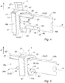
figures 4 à 7 , différentes étapes lors de l'introduction de la clé dans le verrou selon un autre mode de réalisation de l'invention ; -
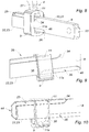
figures 8 à 10 , différentes étapes lors de l'extraction de la clé hors du verrou selon le second mode de réalisation de l'invention ; -
figure 11 , un dispositif antivol de colonne de direction de véhicule automobile selon un troisième mode de réalisation de l'invention.
-
figure 1 , a sectional view of a motor vehicle steering column anti-theft device according to an embodiment of the invention; -
figure 2 , a diagram of the key rod during its insertion into the lock when the control cam is in the retracted position; -
figure 3 , a diagram of the key rod during its insertion into the lock when the control cam is in the projecting position; -
figures 4 to 7 , different steps during the introduction of the key into the lock according to another embodiment of the invention; -
figures 8 to 10 , different steps during the extraction of the key from the lock according to the second embodiment of the invention; -
figure 11 , a motor vehicle steering column anti-theft device according to a third embodiment of the invention.
Le dispositif antivol 2 de colonne de direction de véhicule automobile comprend un verrou 1 comportant un pêne 3 et un moyen de maintien 4 du pêne 3 en translation entre une position de verrouillage de la colonne de direction et une position de libération de la colonne.The
Le pêne 3 coulisse entre une position saillante dans laquelle il verrouille la colonne de direction et une position escamotée dans laquelle il libère la colonne de direction.The
Le verrou 1 comprend un rotor 5 monté en rotation autour d'un axe A dans un stator 6 et une pluralité de paillettes 7 montées à coulissement dans le rotor 5 suivant une direction transversale B entre au moins une position saillante dans laquelle elles immobilisent en rotation le rotor 5 par rapport au stator 6, et une position escamotée à l'intérieur du rotor 5 après l'introduction dans le rotor 5 d'une tige de clé 8, autorisant la rotation du rotor 5.The
Selon l'invention, le verrou 1 comprend une came de commande 9 destinée à suivre au moins le profil d'un chemin de came de commande 10 prévu sur la tige de clé 8 lorsqu'elle est se déplace longitudinalement dans le rotor 5.According to the invention, the
Dans cet exemple, la came de commande 9 est montée à coulissement dans le rotor 5 suivant la direction transversale B entre:
- une position saillante obtenue lorsque la came de commande 9 suit le profil du chemin de came de commande 10 de la tige de clé 8 et
- une position escamotée obtenue lorsque la came de commande 9 suit le profil du chemin de came de commande 10 de la tige de clé 8 lors du retrait de celle-ci.
- a projecting position obtained when the
control cam 9 follows the profile of thecontrol cam path 10 of thekey rod 8 and - a retracted position obtained when the
control cam 9 follows the profile of thecontrol cam path 10 of thekey rod 8 when it is withdrawn.
Dit autrement, la position saillante est obtenue lorsque la came de commande 9 suit le profil montant du chemin de came de commande 10 de la tige de clé 8, le profil montant du chemin de came de commande de la tige de clé étant défini dans le sens d'introduction de la tige de clé.In other words, the projecting position is obtained when the
Et la position escamotée est obtenue lorsque la came de commande 9 suit le profil descendant du chemin de came de commande 10 de la tige de clé 8, le profil descendant du chemin de came de commande de la tige de clé étant défini dans le sens d'extraction ou retrait de la tige de clé.And the retracted position is obtained when the
La came de commande 9 comprend au moins un ergot 11 agencé pour être reçu dans le chemin de came de commande 10 de la tige de clé 8 de manière à suivre le profil de la tige de clé 8 dans le rotor 5 de sorte qu'un déplacement axial de la tige de clé 8 entraine un déplacement de la came de commande 9 selon la direction transversale B.The
L'ergot 11 peut avoir une forme parallélépipédique et s'étendre selon l'axe A.The
La came de commande 9 comprend un orifice central 12 destiné à être traversé par la tige de clé 8. L'ergot 11 est positionné à l'intérieur de l'orifice central 12 et plus précisément sur une paroi interne 15 délimitant l'orifice central 12.The
La came de commande 9 et l'orifice central 12 présentent une forme générale parallélépipédique. La came de commande 9 présente une section générale quadrilatérale, proche de celle des paillettes 7.The
L'orifice central 12 présente une section quadrilatérale. La paroi interne 15 comprend deux parois latérales 15a, 15b opposées de plus grande longueur et deux parois transversales 15c, 15d opposées de plus petite longueur, comme illustré sur les
L'ergot 11 est positionné sur la paroi latérale 15a destinée à être en regards du chemin de came de commande 10 de la tige de clé 8.The
La came de commande 9 est logée à l'intérieur du verrou 1 dans le même logement prévu pour les paillettes 7 et paralèlement aux paillettes 7. La came de commande 9 est alignée avec les paillettes 7.The
La came de commande 9 comprend une surface de contact 14 sur son côté externe de plus faible dimension qui est destinée à venir en contact avec la première extrémité 30 du levier 27.The
De préférence, la surface de contact 14 est courbée.Preferably, the
La came de commande 9 comprend deux surfaces latérales 14a, 14b sur ses côtés externes de plus grande dimension.The
De préférence, la came de commande 9 est positionnée en amont des paillettes 7, à proximité d'une face d'entrée 13 du verrou 1. Cette face d'entrée 13 correspond à la face par laquelle est insérée la clé. Les positions amont et aval sont définies par rapport au sens d'insertion de la clé.Preferably, the
La came de commande 9 est positionnée entre la face d'entrée 13 du verrou 1 et les paillettes 7.The
En variante, la came de commande 9 peut être positionnée différemment, comme par exemple en aval des paillettes 7.As a variant, the
Le moyen de maintien 4 comprend un levier 27 apte à tourner autour un axe de rotation 28 tout en étant apte à translater selon la direction B sous impulsion du ressort 29. Le moyen de maintien 4 comprend en effet un ressort 29 pour maintenir une première extrémité 30 du levier 27 en appui contre la came de commande 9 et la ramener vers la position escamotée correspondant à la position de verrouillage du pêne 3.The holding means 4 comprises a
Le ressort 29 est en appui sur un support 32.The
Le levier 27 comprend une deuxième extrémité 31 coopérant avec le pêne 3 pour maintenir ce dernier en position de libération de pêne.The
La clé destinée à être introduite dans le verrou 1 comprend une tige de clé 8 agencée pour coopérer avec les paillettes 7 du verrou 1 du dispositif antivol 2.The key intended to be introduced into the
La tige de clé 8 présente une section quadrilatérale, allongée dans le sens du coulissement des paillettes 7, et deux faces latérales 16a, 16b opposées dont l'une au moins comprend un chemin de came de codage 17 comportant une succession de crêtes 18 et de creux 19 pour former un codage.The
Le chemin de came de codage 17 est agencé pour recevoir au moins un ergot 20 des paillettes 7 du verrou 1 de manière à ce que les ergots 20 suivent cette succession de crêtes 18 et de creux 19 lors de l'introduction de la tige de clé 8 dans le rotor 5 de sorte qu'un déplacement axial de la clé entraine un déplacement de chacune des paillettes 7 selon la direction transversale B jusqu'à la position saillante en l'occurrence affleurante avec le diamètre du rotor (
Comme dit précédemment, la tige de clé 8 comprend au moins un chemin de came de commande 10 destiné à faire coulisser la came de commande 9 logée dans le rotor 5 du verrou 1 lorsque la tige de clé 8 se déplace dans le rotor 5 suivant la direction transversale B entre la position saillante et la position escamotée.As said previously, the
Les
Le chemin de came de commande 10 est décalé par rapport au chemin de came de codage 17 vers le moyen de maintien 4 du pêne 3 et dans le plan d'une première face latérale 16a de la tige de clé 8.The
Par rapport au plan de la
Le chemin de came de commande 10 est rectiligne, par exemple.The
La came de commande 9 est en position escamotée lorsque la clé n'est pas insérée dans le verrou 1 ou lorsque l'ergot 11 de la came de commande 9 suit le profil du chemin de came de codage 17 de la tige de clé 8 au début de l'insertion de la clé dans le verrou.The
La tige de clé 8 comprend une première tranche 42 et une deuxième tranche 43 opposées et parallèles entres elles.The
Le chemin de came de commande 10 est positionné le long de la première tranche 42 de la tige de clé 8 au plus près de la première extrémité 30 du levier 27.The
Le chemin de came de commande 10 est positionné dans une zone aval 24b de la tige de clé 8 par rapport au sens d'introduction de la clé dans le verrou 1, c'est-à-dire près de l'extrémité arrière 33 de la tige de clé 8 destinée à recevoir un élément de préhension.The
Le chemin de came de commande 10 est taillé en creux ou dit autrement, creusé dans la tige de clé 8.The
Ainsi, lors de l'introduction de la clé dans le verrou 1, les ergots 20 des paillettes 7 et l'ergot 11 de la came de commande 9 suivent le chemin de came de codage 17 de la tige de clé 8, comme représenté sur la
Par opposition, lors de l'extraction de la clé hors du verrou 1, l'ergot 11 de la came de commande 9 suit le profil du chemin de came de commande 10. Lorsqu'il suit celui du chemin de came de codage 17, ceci entraine l'escamotage de la came de commande 9 à l'intérieur du verrou 1. La deuxième extrémité 31 du levier 27 se désengage du pêne 3 pour le libérer et lui permettre de se déployer pour verrouiller la colonne de direction.In contrast, when the key is extracted from the
En variante, la tige de clé 8 peut comprendre symétriquement deux chemins de came de commande 10 disposés sur chaque face latérale 16a, 16b de la tige de clé 8 et coopérant avec deux ergots 11 positionnés en opposition sur la paroi interne 15 de la came de commande 9.As a variant, the
En variante, le chemin de came de commande 10 taillé en creux peut être positionné dans la zone amont 24a de la tige de clé 8 ou déboucher à l'extérieur par l'une des tranches 42, 43 formant un chemin de came de commande externe.As a variant, the
Les
La came de commande 9 comprend deux ergots 11, 11a positionnés sur une paroi interne 15 de l'orifice central 12 dont un premier ergot 11 destiné à déplacer la came de commande 9 en position saillante lorsque le premier ergot 11 suit le profil du chemin de came de commande 10 de la tige de clé 8 et un deuxième ergot 11a destiné à déplacer la came de commande 9 en position escamotée lorsque le deuxième ergot 11a suit le profil d'un chemin de came de commande d'escamotage 23 prévu sur la tige de clé 8.The
Les ergots 11, 11a sont opposés et en regard l'un de l'autre pour coopérer avec les chemins de came de commande 10, 23 qui sont opposés et décalés.The
Ils peuvent avoir une forme parallélépipédique et s'étendent selon l'axe A.They can have a parallelepiped shape and extend along the axis A.
Le chemin de came de commande 10 est alors formé par le premier rebord latéral 21 de la tige de clé 8 formé sur la première tranche 42 et est destiné à guider le premier ergot 11 de la came de commande 9.The
Le premier rebord latéral 21 est positionné dans la zone aval 24b de la tige de clé 8 par rapport au sens d'introduction de la clé dans le verrou 1.The first lateral flange 21 is positioned in the
Le deuxième rebord latéral 22 opposé au premier rebord latéral 21 de la tige de clé 8 et formé sur la deuxième tranche 43, forme un chemin de came de commande d'escamotage 23 de la came de commande 9 destiné à guider le deuxième ergot 11a de la came de commande 9.The second lateral rim 22 opposite the first lateral rim 21 of the
Le deuxième rebord latéral 22 est positionné dans une zone amont 24a de la tige de clé 8 par rapport au sens d'introduction de la clé dans le verrou 1.The second lateral flange 22 is positioned in an
Le deuxième rebord latéral 22 se prolonge jusqu'à une extrémité avant 44 de la clé.The second lateral flange 22 extends to a
La tige de clé 8 comprend une première gorge de guidage 25 creusée dans sa première face latérale 16a et positionnée dans la zone amont 24a.The
La première gorge de guidage 25 est décalée par rapport au premier rebord latéral 21, vers une direction opposée au moyen de maintien 4 du pêne 3 et dans le plan de la première face latérale 16a.The
La première gorge de guidage 25 est creusée le long et dans une portion de la première tranche 42 de la tige de clé 8.The
La première gorge de guidage 25 présente une forme allongée, rectiligne, est de section sensiblement quadrilatèrale et se prolonge jusqu'à une extrémité avant 44 de la clé.The
Une première marche 34 est formée entre la première gorge de guidage 25 et le premier rebord latéral 21.A
La tige de clé 8 comprend une deuxième gorge de guidage 26 creusée dans sa première face latérale 16a, et prolongeant le deuxième rebord latéral 22 de façon décalée.The
La deuxième gorge de guidage 26 est creusée le long et dans une portion de la deuxième tranche 43 de la tige de clé 8 opposée à la première tranche 42.The
Une deuxième marche 35 est formée entre la deuxième gorge de guidage 26 et le deuxième rebord latéral 22.A
La deuxième gorge de guidage 26 présente une forme allongée, rectiligne, et est de section sensiblement quadrilatèrale.The
Les gorges de guidage 25, 26 sont opposées et partiellement décalées l'une par rapport à l'autre suivant la direction de l'axe A et dans le plan des faces latérales 16a, 16b.The
La première gorge de guidage 25 et la deuxième gorge de guidage 26 sont à l'extérieur de la tige de clé 8.The
La première gorge de guidage 25 est délimitée par une première paroi 36 parallèle à la première face latérale 16a de la tige de clé 8 et une deuxième paroi 37, parallèle au premier rebord latéral 21. La première paroi 36 est perpendiculaire à la deuxième paroi 37.The
La première marche 34 est formée par une paroi reliant le premier rebord latéral 21 à la deuxième paroi 37. La première marche 34 est de préférence sensiblement inclinée par rapport à la deuxième paroi 37 et au premier rebord latéral 21 avec des portions arrondies à ses extrémités pour faciliter le glissement de l'ergot.The
La deuxième gorge de guidage 26 est délimitée par une première paroi 38 parallèle à la première face latérale 16a de la tige de clé 8 et une deuxième paroi 39, parallèle au deuxième rebord latéral 22. La première paroi 38 est perpendiculaire à la deuxième paroi 39.The
La deuxième marche 35 est formée par une paroi reliant le deuxième rebord latéral 22 à la deuxième paroi 39 de la deuxième gorge de guidage 26. La deuxième marche 35 est de préférence sensiblement inclinée par rapport à la deuxième paroi 39 et au deuxième rebord latéral 22 avec des portions arrondies à ses extrémités pour faciliter le glissement de l'ergot.The
La deuxième gorge de guidage 26 est également délimitée par une paroi aval 46, opposée à la deuxième marche 35.The
La première gorge de guidage 25 et la deuxième gorge de guidage 26 se chevauchent partiellement de manière à présenter une portion 40, 41 respective en regard l'une de l'autre.The
Les
Lors de l'introduction de la clé dans le verrou 1, comme illustrée sur la
La came de commande 9 reste ainsi en position escamotée dans laquelle le pêne 3 est en position de verrouillage de la colonne de direction.The
Comme représenté sur la
Parallèlement, le deuxième ergot 11a longe la deuxième gorge de guidage 26 sans être en contact avec elle. La came de commande 9 reste toujours en position escamotée.In parallel, the
Comme représenté sur les
Le premier rebord latéral 21 formant le chemin de came de commande 10 étant décalé en hauteur par rapport à la première gorge de guidage 25 dans le plan de la première face latérale 16a, la came de commande 9 se déplace de la position escamotée vers la position saillante, actionnant le moyen de maintien 4 vers sa position de maintien du pêne 3 en position de libération de la colonne de direction.The first lateral edge 21 forming the
Le deuxième ergot 11a s'engage alors dans la deuxième gorge de guidage 26 pour coulisser le long de celle-ci jusqu'à l'insertion complète de la clé dans le verrou 1.The
La
Les
Lors de l'extraction de la clé hors du verrou 1, comme représentée sur les
Le premier ergot 11 se retrouve face à la première gorge de guidage 25 sans être obligatoirement en contact avec elle, au niveau des portions 40, 41.The
Le franchissement de la deuxième marche 35 par le deuxième ergot 11a, comme illustré sur la
La deuxième gorge de guidage 26 étant décalée en hauteur par rapport au deuxième rebord latéral 22 formant le chemin de came de commande d'escamotage 23, dans le plan de la première face latérale 16a, la came de commande 9 se déplace de la position saillante vers la position escamotée, actionnant le moyen de maintien 4 dans sa position de libération du pêne 3 qui sera apte à entrer dans sa position de verrouillage de la colonne de direction.The
Le premier ergot 11 s'engage dans la première gorge de guidage 25 et coulisse alors le long de celle-ci jusqu'à l'extrémité avant 44 de la clé et l'extraction complète de la clé hors du verrou 1.The
En variante, la première gorge de guidage 25 peut être positionnée sur la première face latérale 16a et la deuxième gorge de guidage 26 peut être positionnée sur la deuxième face latérale 16b de la tige de clé 8.As a variant, the
En variante, la deuxième face latérale 16b de la tige de clé 8 peut également comprendre une autre première gorge de guidage 25 et une autre deuxième gorge de guidage 26 disposées en symétrie avec celles positionnées sur la première face latérale 16a.Alternatively, the
La came de commande 9 peut comprendre une rainure latérale de guidage 45 pour améliorer son coulissement dans le logement du verrou 1.The
La
La came de commande 9 est montée en rotation sur le rotor 5 autour d'un axe de rotation C perpendiculaire à l'axe de rotation A du rotor 5.The
Le moyen de maintien 4 du dispositif antivol 2 comprend un levier 27 monté en rotation autour de l'axe de rotation C.The holding means 4 of the
La came de commande 9 est solidaire ou intégrée au levier 27 du moyen de maintien 4 du dispositif antivol 2.The
La première extrémité 30 du levier 27 est fixée à la came de commande 9.The
La deuxième extrémité 31 du levier 27 est apte à maintenir le pêne 3 dans sa position de libération de la colonne de direction.The
La came de commande 9 comprend un ergot 11 agencé pour être reçu dans le chemin de came de commande 10 de la tige de clé 8 de manière à suivre son profil lors de l'introduction ou du retrait de la tige de clé 8 dans le rotor 5 de sorte qu'un déplacement axial de la tige de clé 8 entraine une rotation de la came de commande 9 dans le plan de la
Lors de l'insertion de la tige de clé 8, l'ergot 11 de la came de commande 9 s'insère dans le chemin de came de commande 10 de la tige de clé 8, entraînant la rotation du levier 27.When the
Lors de l'extraction de la tige de clé 8, l'ergot 11 de la came de commande 9 suit aussi le chemin de came de commande 10 de la tige de clé 8, le levier 27 est en outre entraîné en rotation dans un sens opposé à celui de l'insertion, sous l'effet additionnel d'un ressort (non représenté) qui va maintenir la position escamotée.When extracting the
Si selon l'invention il existe un ressort, ce dernier n'est présent que pour maintenir le contact du levier avec la came de commande ou la ramener en position escamotée.If according to the invention there is a spring, the latter is only present to maintain contact of the lever with the control cam or return it to the retracted position.
L'invention est décrite dans ce qui précède à titre d'exemple. Il est entendu que l'homme du métier est à même de réaliser différentes variantes de réalisation de l'invention sans pour autant sortir du cadre de l'invention.The invention is described in the foregoing by way of example. It is understood that a person skilled in the art is able to carry out different alternative embodiments of the invention without going beyond the ambit of the invention.
Claims (14)
Applications Claiming Priority (1)
| Application Number | Priority Date | Filing Date | Title |
|---|---|---|---|
| FR1872631A FR3089472B1 (en) | 2018-12-10 | 2018-12-10 | Lock and key for motor vehicle steering column anti-theft device |
Publications (1)
| Publication Number | Publication Date |
|---|---|
| EP3666606A1 true EP3666606A1 (en) | 2020-06-17 |
Family
ID=66218237
Family Applications (1)
| Application Number | Title | Priority Date | Filing Date |
|---|---|---|---|
| EP19212973.2A Withdrawn EP3666606A1 (en) | 2018-12-10 | 2019-12-02 | Lock and key for vehicle steering column antitheft device |
Country Status (2)
| Country | Link |
|---|---|
| EP (1) | EP3666606A1 (en) |
| FR (1) | FR3089472B1 (en) |
Citations (7)
| Publication number | Priority date | Publication date | Assignee | Title |
|---|---|---|---|---|
| FR2480213A1 (en) * | 1980-04-15 | 1981-10-16 | Bakony Fem Elektromoskeszulek | STEERING LOCK WITH BUILT-IN IGNITION SWITCH AND DOUBLE LOCK FOR MOTOR VEHICLES |
| EP1772576A2 (en) * | 2005-10-05 | 2007-04-11 | Kabushiki Kaisha Tokai-Rika-Denki-Seisakusho | Cylinder lock and key |
| WO2008074726A1 (en) | 2006-12-19 | 2008-06-26 | Valeo Securite Habitacle | Anti-theft security device for vehicles |
| WO2012019757A1 (en) * | 2010-08-10 | 2012-02-16 | Volkswagen Aktiengesellschaft | Lock device |
| EP2679453A1 (en) * | 2012-06-29 | 2014-01-01 | Huf Hülsbeck & Fürst GmbH & Co. KG | Mechanical steering lock |
| WO2014096054A1 (en) * | 2012-12-21 | 2014-06-26 | U-Shin France Sas | Contact actuator for a motor vehicle |
| CN106917538A (en) * | 2015-12-24 | 2017-07-04 | 黄伟敏 | Blade locking head |
-
2018
- 2018-12-10 FR FR1872631A patent/FR3089472B1/en active Active
-
2019
- 2019-12-02 EP EP19212973.2A patent/EP3666606A1/en not_active Withdrawn
Patent Citations (7)
| Publication number | Priority date | Publication date | Assignee | Title |
|---|---|---|---|---|
| FR2480213A1 (en) * | 1980-04-15 | 1981-10-16 | Bakony Fem Elektromoskeszulek | STEERING LOCK WITH BUILT-IN IGNITION SWITCH AND DOUBLE LOCK FOR MOTOR VEHICLES |
| EP1772576A2 (en) * | 2005-10-05 | 2007-04-11 | Kabushiki Kaisha Tokai-Rika-Denki-Seisakusho | Cylinder lock and key |
| WO2008074726A1 (en) | 2006-12-19 | 2008-06-26 | Valeo Securite Habitacle | Anti-theft security device for vehicles |
| WO2012019757A1 (en) * | 2010-08-10 | 2012-02-16 | Volkswagen Aktiengesellschaft | Lock device |
| EP2679453A1 (en) * | 2012-06-29 | 2014-01-01 | Huf Hülsbeck & Fürst GmbH & Co. KG | Mechanical steering lock |
| WO2014096054A1 (en) * | 2012-12-21 | 2014-06-26 | U-Shin France Sas | Contact actuator for a motor vehicle |
| CN106917538A (en) * | 2015-12-24 | 2017-07-04 | 黄伟敏 | Blade locking head |
Also Published As
| Publication number | Publication date |
|---|---|
| FR3089472B1 (en) | 2022-04-01 |
| FR3089472A1 (en) | 2020-06-12 |
Similar Documents
| Publication | Publication Date | Title |
|---|---|---|
| EP2179115B1 (en) | Key for operating a lock with enhanced impact resistance | |
| EP1084915A1 (en) | Vehicle steering anti-theft device | |
| EP2121392B1 (en) | Anti-theft security device for vehicles | |
| FR2521505A1 (en) | ANTI-THEFT FOR MOTOR VEHICLES | |
| EP3666606A1 (en) | Lock and key for vehicle steering column antitheft device | |
| FR2600365A1 (en) | MECHANISM FOR KEYLESS LOCKING SYSTEMS | |
| FR2943706A1 (en) | KEY FOR CYLINDER PUMPS | |
| EP2104622B1 (en) | Security antitheft device for a vehicle including a slider with an elastic tab | |
| FR2638132A1 (en) | DEVICE FOR IMMOBILIZATION IN ROTATION AND / OR TRANSLATION IN RELATION TO A SUPPORT OF A GUIDE SHAFT IN AT LEAST ONE OF THESE MOVEMENTS RELATING TO THE SUPPORT AND IN PARTICULAR OF A STEERING SHAFT | |
| EP1953048A1 (en) | Device for locking the steering shaft of a vehicle | |
| EP2635465B1 (en) | Antitheft device for vehicle steering column with push-in safety function | |
| FR3109141A1 (en) | Articulation hinge between two panels of an aircraft propulsion unit | |
| EP1637415B2 (en) | Electrical device for locking/unlocking a steering column | |
| FR2716484A1 (en) | Burglary detector and preventer for security lock | |
| EP2746115B1 (en) | Contact actuator for a vehicle | |
| EP3498944A1 (en) | Spanner and cylinder for security lock | |
| EP3569799B1 (en) | Locking actuating assembly with a key | |
| EP2496447B1 (en) | Vehicle antitheft device for a steering column having an lost motion actuator for a bolt | |
| FR2710307A1 (en) | Anti-theft precaution especially for motorbikes with disc brakes | |
| EP0424288B1 (en) | Door lock, and door frame incorporating such a lock | |
| EP3233587B1 (en) | Antitheft device for steering column | |
| EP2746114B1 (en) | Contact actuator for a vehicle | |
| EP0869236B1 (en) | Safety cylinder operable from one side even when a key is inserted in the opposite side | |
| FR2631907A1 (en) | Steering lock anti-theft device for motor vehicles | |
| FR2711102A1 (en) | Security device, in particular anti-theft device for vehicle steering |
Legal Events
| Date | Code | Title | Description |
|---|---|---|---|
| PUAI | Public reference made under article 153(3) epc to a published international application that has entered the european phase |
Free format text: ORIGINAL CODE: 0009012 |
|
| STAA | Information on the status of an ep patent application or granted ep patent |
Free format text: STATUS: THE APPLICATION HAS BEEN PUBLISHED |
|
| AK | Designated contracting states |
Kind code of ref document: A1 Designated state(s): AL AT BE BG CH CY CZ DE DK EE ES FI FR GB GR HR HU IE IS IT LI LT LU LV MC MK MT NL NO PL PT RO RS SE SI SK SM TR |
|
| AX | Request for extension of the european patent |
Extension state: BA ME |
|
| STAA | Information on the status of an ep patent application or granted ep patent |
Free format text: STATUS: REQUEST FOR EXAMINATION WAS MADE |
|
| 17P | Request for examination filed |
Effective date: 20201110 |
|
| RBV | Designated contracting states (corrected) |
Designated state(s): AL AT BE BG CH CY CZ DE DK EE ES FI FR GB GR HR HU IE IS IT LI LT LU LV MC MK MT NL NO PL PT RO RS SE SI SK SM TR |
|
| RAP3 | Party data changed (applicant data changed or rights of an application transferred) |
Owner name: U-SHIN FRANCE |
|
| GRAP | Despatch of communication of intention to grant a patent |
Free format text: ORIGINAL CODE: EPIDOSNIGR1 |
|
| STAA | Information on the status of an ep patent application or granted ep patent |
Free format text: STATUS: GRANT OF PATENT IS INTENDED |
|
| INTG | Intention to grant announced |
Effective date: 20230404 |
|
| RAP3 | Party data changed (applicant data changed or rights of an application transferred) |
Owner name: MINEBEA ACCESSSOLUTIONS FRANCE |
|
| STAA | Information on the status of an ep patent application or granted ep patent |
Free format text: STATUS: THE APPLICATION IS DEEMED TO BE WITHDRAWN |
|
| 18D | Application deemed to be withdrawn |
Effective date: 20230815 |