EP3666603A1 - Safety device for vehicle - Google Patents
Safety device for vehicle Download PDFInfo
- Publication number
- EP3666603A1 EP3666603A1 EP19169242.5A EP19169242A EP3666603A1 EP 3666603 A1 EP3666603 A1 EP 3666603A1 EP 19169242 A EP19169242 A EP 19169242A EP 3666603 A1 EP3666603 A1 EP 3666603A1
- Authority
- EP
- European Patent Office
- Prior art keywords
- airbag chamber
- vehicle
- chamber
- safety device
- vehicle occupant
- Prior art date
- Legal status (The legal status is an assumption and is not a legal conclusion. Google has not performed a legal analysis and makes no representation as to the accuracy of the status listed.)
- Granted
Links
Images



Classifications
-
- B—PERFORMING OPERATIONS; TRANSPORTING
- B60—VEHICLES IN GENERAL
- B60R—VEHICLES, VEHICLE FITTINGS, OR VEHICLE PARTS, NOT OTHERWISE PROVIDED FOR
- B60R21/00—Arrangements or fittings on vehicles for protecting or preventing injuries to occupants or pedestrians in case of accidents or other traffic risks
- B60R21/02—Occupant safety arrangements or fittings, e.g. crash pads
- B60R21/16—Inflatable occupant restraints or confinements designed to inflate upon impact or impending impact, e.g. air bags
- B60R21/20—Arrangements for storing inflatable members in their non-use or deflated condition; Arrangement or mounting of air bag modules or components
- B60R21/207—Arrangements for storing inflatable members in their non-use or deflated condition; Arrangement or mounting of air bag modules or components in vehicle seats
-
- B—PERFORMING OPERATIONS; TRANSPORTING
- B60—VEHICLES IN GENERAL
- B60N—SEATS SPECIALLY ADAPTED FOR VEHICLES; VEHICLE PASSENGER ACCOMMODATION NOT OTHERWISE PROVIDED FOR
- B60N2/00—Seats specially adapted for vehicles; Arrangement or mounting of seats in vehicles
- B60N2/75—Arm-rests
- B60N2/79—Adaptations for additional use of the arm-rests
-
- B—PERFORMING OPERATIONS; TRANSPORTING
- B60—VEHICLES IN GENERAL
- B60R—VEHICLES, VEHICLE FITTINGS, OR VEHICLE PARTS, NOT OTHERWISE PROVIDED FOR
- B60R21/00—Arrangements or fittings on vehicles for protecting or preventing injuries to occupants or pedestrians in case of accidents or other traffic risks
- B60R21/02—Occupant safety arrangements or fittings, e.g. crash pads
- B60R21/16—Inflatable occupant restraints or confinements designed to inflate upon impact or impending impact, e.g. air bags
- B60R21/23—Inflatable members
- B60R21/231—Inflatable members characterised by their shape, construction or spatial configuration
- B60R21/23138—Inflatable members characterised by their shape, construction or spatial configuration specially adapted for side protection
-
- B—PERFORMING OPERATIONS; TRANSPORTING
- B60—VEHICLES IN GENERAL
- B60R—VEHICLES, VEHICLE FITTINGS, OR VEHICLE PARTS, NOT OTHERWISE PROVIDED FOR
- B60R21/00—Arrangements or fittings on vehicles for protecting or preventing injuries to occupants or pedestrians in case of accidents or other traffic risks
- B60R21/02—Occupant safety arrangements or fittings, e.g. crash pads
- B60R21/16—Inflatable occupant restraints or confinements designed to inflate upon impact or impending impact, e.g. air bags
- B60R21/23—Inflatable members
- B60R21/231—Inflatable members characterised by their shape, construction or spatial configuration
- B60R21/233—Inflatable members characterised by their shape, construction or spatial configuration comprising a plurality of individual compartments; comprising two or more bag-like members, one within the other
-
- B—PERFORMING OPERATIONS; TRANSPORTING
- B60—VEHICLES IN GENERAL
- B60R—VEHICLES, VEHICLE FITTINGS, OR VEHICLE PARTS, NOT OTHERWISE PROVIDED FOR
- B60R21/00—Arrangements or fittings on vehicles for protecting or preventing injuries to occupants or pedestrians in case of accidents or other traffic risks
- B60R21/02—Occupant safety arrangements or fittings, e.g. crash pads
- B60R21/16—Inflatable occupant restraints or confinements designed to inflate upon impact or impending impact, e.g. air bags
- B60R21/23—Inflatable members
- B60R21/231—Inflatable members characterised by their shape, construction or spatial configuration
- B60R21/2334—Expansion control features
- B60R21/2338—Tethers
-
- B—PERFORMING OPERATIONS; TRANSPORTING
- B60—VEHICLES IN GENERAL
- B60R—VEHICLES, VEHICLE FITTINGS, OR VEHICLE PARTS, NOT OTHERWISE PROVIDED FOR
- B60R21/00—Arrangements or fittings on vehicles for protecting or preventing injuries to occupants or pedestrians in case of accidents or other traffic risks
- B60R21/02—Occupant safety arrangements or fittings, e.g. crash pads
- B60R21/16—Inflatable occupant restraints or confinements designed to inflate upon impact or impending impact, e.g. air bags
- B60R21/26—Inflatable occupant restraints or confinements designed to inflate upon impact or impending impact, e.g. air bags characterised by the inflation fluid source or means to control inflation fluid flow
- B60R21/264—Inflatable occupant restraints or confinements designed to inflate upon impact or impending impact, e.g. air bags characterised by the inflation fluid source or means to control inflation fluid flow using instantaneous generation of gas, e.g. pyrotechnic
-
- B—PERFORMING OPERATIONS; TRANSPORTING
- B60—VEHICLES IN GENERAL
- B60R—VEHICLES, VEHICLE FITTINGS, OR VEHICLE PARTS, NOT OTHERWISE PROVIDED FOR
- B60R21/00—Arrangements or fittings on vehicles for protecting or preventing injuries to occupants or pedestrians in case of accidents or other traffic risks
- B60R2021/0002—Type of accident
- B60R2021/0004—Frontal collision
-
- B—PERFORMING OPERATIONS; TRANSPORTING
- B60—VEHICLES IN GENERAL
- B60R—VEHICLES, VEHICLE FITTINGS, OR VEHICLE PARTS, NOT OTHERWISE PROVIDED FOR
- B60R21/00—Arrangements or fittings on vehicles for protecting or preventing injuries to occupants or pedestrians in case of accidents or other traffic risks
- B60R2021/0002—Type of accident
- B60R2021/0006—Lateral collision
-
- B—PERFORMING OPERATIONS; TRANSPORTING
- B60—VEHICLES IN GENERAL
- B60R—VEHICLES, VEHICLE FITTINGS, OR VEHICLE PARTS, NOT OTHERWISE PROVIDED FOR
- B60R21/00—Arrangements or fittings on vehicles for protecting or preventing injuries to occupants or pedestrians in case of accidents or other traffic risks
- B60R21/01—Electrical circuits for triggering passive safety arrangements, e.g. airbags, safety belt tighteners, in case of vehicle accidents or impending vehicle accidents
- B60R2021/01204—Actuation parameters of safety arrangents
- B60R2021/01211—Expansion of air bags
-
- B—PERFORMING OPERATIONS; TRANSPORTING
- B60—VEHICLES IN GENERAL
- B60R—VEHICLES, VEHICLE FITTINGS, OR VEHICLE PARTS, NOT OTHERWISE PROVIDED FOR
- B60R21/00—Arrangements or fittings on vehicles for protecting or preventing injuries to occupants or pedestrians in case of accidents or other traffic risks
- B60R21/02—Occupant safety arrangements or fittings, e.g. crash pads
- B60R21/16—Inflatable occupant restraints or confinements designed to inflate upon impact or impending impact, e.g. air bags
- B60R21/20—Arrangements for storing inflatable members in their non-use or deflated condition; Arrangement or mounting of air bag modules or components
- B60R21/215—Arrangements for storing inflatable members in their non-use or deflated condition; Arrangement or mounting of air bag modules or components characterised by the covers for the inflatable member
- B60R21/216—Arrangements for storing inflatable members in their non-use or deflated condition; Arrangement or mounting of air bag modules or components characterised by the covers for the inflatable member comprising tether means for limitation of cover motion during deployment
- B60R2021/2161—Arrangements for storing inflatable members in their non-use or deflated condition; Arrangement or mounting of air bag modules or components characterised by the covers for the inflatable member comprising tether means for limitation of cover motion during deployment the cover being displaced towards the occupant during deployment
-
- B—PERFORMING OPERATIONS; TRANSPORTING
- B60—VEHICLES IN GENERAL
- B60R—VEHICLES, VEHICLE FITTINGS, OR VEHICLE PARTS, NOT OTHERWISE PROVIDED FOR
- B60R21/00—Arrangements or fittings on vehicles for protecting or preventing injuries to occupants or pedestrians in case of accidents or other traffic risks
- B60R21/02—Occupant safety arrangements or fittings, e.g. crash pads
- B60R21/16—Inflatable occupant restraints or confinements designed to inflate upon impact or impending impact, e.g. air bags
- B60R21/23—Inflatable members
- B60R21/231—Inflatable members characterised by their shape, construction or spatial configuration
- B60R21/23138—Inflatable members characterised by their shape, construction or spatial configuration specially adapted for side protection
- B60R2021/23146—Inflatable members characterised by their shape, construction or spatial configuration specially adapted for side protection seat mounted
Definitions
- the present disclosure relates to a safety device for a vehicle, in which, when a vehicle has a collision, an airbag cushion inflates from an armrest to absorb physical shock, thereby protecting a vehicle occupant.
- seats such as a driver seat and a passenger seat can rotate in order that a driver faces in the backward direction or that the driver and a passenger face each other.
- an airbag cushion expand from an armrest to protect the vehicle occupant against all collisions in the forward direction and the horizontal direction.
- the present disclosure provides a safety device for a vehicle in which, when a vehicle has a collision, an airbag cushion expands from an armrest and physical shock is sufficiently absorbed to protect a vehicle occupant who sits on a seat.
- a safety device for a vehicle including: a main armrest; an auxiliary armrest that obliquely extends from a front end portion of the main armrest toward the center of a seat; a lateral-body chamber that is mounted in the main armrest and that, when triggered to expand, expands upward along a lateral body of a vehicle occupant and thus laterally holds the lateral body of the vehicle occupant in place; and a front-body abdominal chamber that is mounted in the auxiliary armrest and that, when triggered to expand, expands toward an abdomen of the vehicle occupant and thus holds a front body of the vehicle occupant in place.
- the lateral-body chamber may be configured to include a first airbag chamber that is mounted in the main armrest and that, when triggered to expand, expands upward along the lateral body of the vehicle occupant and thus laterally holds an arm of the vehicle occupant in place, and a second airbag chamber that extends protrusively from an upper end portion of the first airbag chamber toward a neck of the vehicle occupant and thus holds a shoulder of the vehicle occupant in place.
- the first airbag chamber and the second airbag chamber may be spatially separated from each other by an inner panel that traverses the inside of one airbag chamber, a through-hole through which gas flows between the first airbag chamber and the second airbag chamber may be formed in the inner panel, and the first airbag chamber may be supplied with gas from an inflater of the main armrest and thus may swell and the second airbag chamber may be supplied with gas from the first airbag chamber through the through-hole and thus may swell.
- the safety device for a vehicle may further include an obliquely-positioned tether one end of which is coupled to an outside surface that faces the vehicle occupant, of the first airbag chamber and the other end of which is coupled to an outside surface that faces the vehicle occupant, of the second airbag chamber, in which, when the expansion is in progress, the obliquely-positioned tether may enable the second airbag chamber to maintain a state of expanding protrusively from the first airbag chamber.
- the safety device for a vehicle may further include a holding tether, one end of which is coupled to a rear end portion of the first airbag chamber and the other end of which is coupled to a lateral side of a seat back, in which, when the expansion is in progress, the holding tether may prevent or inhibit the first airbag chamber from moving in a forward direction.
- a holding tether cutter may be provided on the holding tether, and, in a case where a reclining angle of the seat back falls within a fixed range, when the first airbag chamber expands, the holding tether cutter may cut off the holding tether.
- the holding tether cutter may be provided on the main armrest and may be coupled to the other end of the holding tether.
- one end of the holding tether may be coupled to a rear end portion of the first airbag chamber and the other end may extend along a lateral side of the back seat and then may be coupled to the main armrest.
- the safety device for a vehicle may further include a fourth airbag chamber that extends protrusively from a part of a front portion of the first airbag chamber, which is positioned below the second airbag chamber, toward a chest region of the vehicle occupant, in which the fourth airbag chamber may be positioned between a lower end of the second airbag chamber and an upper end of the front-body abdominal chamber and may prevent or inhibit the arm or shoulder of the vehicle occupant from moving in the forward direction.
- the safety device for a vehicle may further include a fifth airbag chamber that extends from a rear portion of the front-side abdominal chamber toward the pelvic region of the vehicle occupant in which the fifth airbag chamber may expand between the main armrest and a pelvic region of the vehicle occupant.
- the safety device for a vehicle may further include a chamber that extends upward from an upper surface portion of the front-body abdominal chamber and holds the front body of the vehicle occupant in place.
- sixth airbag chambers in a pair may be provided on the left and right sides, respectively, of the seat, and the sixth airbag chamber that is provided on one of the left and right sides may extend upward to have an area that is larger than that of the sixth airbag chamber that is provided on the other one.
- the sixth airbag chamber that is provided on one of the left and right sides when triggered to expand, the sixth airbag chamber that is provided on one of the left and right sides may be positioned closer to the vehicle occupant than the sixth airbag chamber that is provided on the other one, and, in a state where the expansion is completed, a front surface portion of the sixth airbag chamber that is provided on one of the left and right sides may be supported by the sixth airbag chamber that is provided on the other one.
- the auxiliary armrest may be coupled, with a rotation shaft, to the front end portion of the main armrest, and, when an airbag expands, the auxiliary armrest may rotate from the front end portion of the main armrest toward the center of the seat.
- the auxiliary armrest may be accommodated into the main armrest, and, when the airbag expands, may be slit to protrude in the same direction in which the main armrest faces forward.
- the auxiliary armrest when slid to protrude, may be guided by a guide within the main armrest and thus may protrude obliquely toward the center of the seat.
- an airbag cushion expands from an armrest and physical shock is sufficiently absorbed to protect a vehicle occupant who sits on a seat.
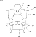
- FIG. 1 is a front-view diagram illustrating a front side of a safety device for a vehicle according to an aspect of the present disclosure.
- FIG. 2 is a diagram illustrating an inner panel and a through-hole in the safety device for a vehicle according to the aspect of the present disclosure.
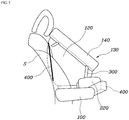
- FIG. 3 is a side-view diagram illustrating a left lateral side of the safety device for a vehicle according to the aspect of the present disclosure.
- FIG. 4 is a diagram illustrating a side-view diagram illustrating a right lateral side of the safety device for a vehicle according to the aspect of the present disclosure.
- FIG. 5 is a perspective-view diagram illustrating a safety device for a vehicle according to another aspect of the present disclosure.
- FIG. 1 is a front-view diagram illustrating a front side of a safety device for a vehicle according to an aspect of the present disclosure.
- FIG. 2 is a diagram illustrating an inner panel and a through-hole in the safety device for a vehicle according to the aspect of the present disclosure.
- FIG. 6 is a front-view diagram illustrating a safety device for a vehicle according to still another aspect of the present disclosure.
- FIG. 7 is a diagram illustrating a state where an auxiliary armrest of a safety device for a vehicle according to still another aspect of the present disclosure is rotated.
- FIG. 8 is a diagram illustrating a state where an auxiliary armrest of a safety device for a vehicle according to still another aspect of the present disclosure expands.
- FIG. 1 is a front-view diagram of a safety device for a vehicle.
- a safety device for a vehicle includes a main armrest 100, an auxiliary armrest 200 that obliquely extends from a front end portion of the main armrest 100 toward the center of a seat, a lateral-body chamber 130 that is mounted in the main armrest 100 and that, when triggered to expand, expands upward along a lateral body of a vehicle occupant and thus laterally holds the lateral body of the vehicle occupant in place, and a front-body abdominal chamber 220 that is mounted in the auxiliary armrest 200 and that, when triggered to expand, expands toward an abdomen of the vehicle occupant and thus holds a front body of the vehicle occupant in place.
- the safety device for a vehicle includes the main armrest 100 and the auxiliary armrest 200. As illustrated in FIG. 1 , the main armrest 100 is coupled to a lateral side of the seat.
- the lateral-body chamber 130 expands upward along the lateral body of the vehicle occupant and thus performs a function of absorbing physical shock, which propagates from the leftward-rightward direction, to the vehicle occupant.
- the lateral-body chamber 130 performs not only the function of absorbing the physical shock in the horizontal direction to the lateral body of the vehicle occupant, but also performs a function of absorbing physical shock, which propagates from the forward direction, to a shoulder region of the vehicle occupant.
- the front-body abdominal chamber 220 expands toward the abdomen of the vehicle occupant, and thus the auxiliary armrest 200 absorbs physical shock, which propagates from the forward direction, to the vehicle occupant and, at the same time, protects the abdomen of the vehicle occupant. That is, airbag chambers absorb physical shock, which propagates from the leftward-rightward direction and the forward direction, to the vehicle occupant and a seat back S serves as a support stand in rear of the vehicle occupant. This serves to guard against the physical shock in all directions. More specifically, as illustrated in FIG.
- the lateral-body chamber 130 is configured to include a first airbag chamber 120 that is mounted in the main armrest 100 and that, when triggered to expand, expands upward along the lateral body of the vehicle occupant and thus laterally holds an arm of the vehicle occupant in place, and a second airbag chamber 140 that extends protrusively from an upper end portion of the first airbag chamber 120 toward a neck of the vehicle occupant and thus holds a shoulder of the vehicle occupant in place.
- the lateral-body chamber 130 is configured to include the first airbag chamber 120 and the second airbag chamber 140 that possibly extends from the first airbag chamber 120.
- the second airbag chamber 140 is enabled to extend protrusively in a suitable manner to hold the shoulder of the vehicle occupant in place.
- the first airbag chamber 120 and the second airbag chamber 140 hold the arm and the shoulder, respectively, of the vehicle occupant in place. This provides the advantage that the upper body of the vehicle occupant is tightly held in place.
- the first airbag chamber 120 and the second airbag chamber 140 are spatially separated from each other by an inner panel 160 that traverses the inside of one airbag chamber.
- a through-hole 165 through which gas flows between the first airbag chamber 120 and the second airbag chamber 140 is formed in the inner panel 160.
- the first airbag chamber 120 is supplied with gas from an inflater of the main armrest 100 and thus swells.
- the second airbag chamber 140 is supplied with gas from the first airbag chamber 120 through the through-hole 165 and thus swells. If the first airbag chamber 120 and the second airbag chamber 140 expand at the same time, the second airbag chamber 140 comes into physical collision with the arm of the vehicle occupant.
- the second airbag chamber 140 expands later than the first airbag chamber 120.
- the inner panel 160 separates the first airbag chamber 120 and the second airbag chamber 140 from each other.
- the through-hole 165 is formed in the inner panel 160.
- the second airbag chamber 140 expands due to the gas that flows through the through-hole 165 ("A" in FIG. 2 ). Accordingly, the second airbag chamber 140 expands at a later time than the first airbag chamber 120. Therefore, after the first airbag chamber 120 expands almost to maximum size, the second airbag chamber 140 starts to expand. Thus, the second airbag chamber 140 does not come into physical collision with the arm or shoulder of the vehicle occupant.
- the safety device for a vehicle further includes an obliquely-positioned tether 300 one end of which is coupled to an outside surface that faces the vehicle occupant, of the first airbag chamber 120 and the other end of which is coupled to an outside surface that faces the vehicle occupant, of the second airbag chamber 140.
- the obliquely-positioned tether 300 enables the second airbag chamber 140 to maintain a state of expanding protrusively from the first airbag chamber 120.
- the obliquely-positioned tether 300 connects between the first airbag chamber 120 and the second airbag chamber 140, thereby inhibiting the second airbag chamber 140 from expanding only in the upward direction. Therefore, the shoulder of the vehicle occupant is safely protected against the collision.
- the safety device for a vehicle further includes a holding tether 400 one end of which is coupled to a rear end portion of the first airbag chamber 120 and the other end of which is coupled to a lateral side of the seat back S.
- the holding tether 400 prevents or inhibits the first airbag chamber 120 from moving in a forward direction.
- the holding tether 400 is caused to be coupled to the rear end portion of the first airbag chamber 120 and the lateral side of the seat back S.
- the first airbag chamber 120 and the second airbag chamber 140 are supported so strongly that the vehicle occupant is prevented or inhibited from moving in the forward direction.
- a holding tether cutter 420 is provided on the holding tether 400.
- the holding tether cutter 420 cuts the holding tether 400.
- the holding tether cutter 420 provides support through the holding tether 400 in order for the vehicle occupant to move in the forward direction.
- the holding tether 400 is cut off by the hold tether cutter 420 in order to reduce the force of inertia that is exerted on the vehicle occupant. Accordingly, the first airbag chamber 120 and the second airbag chamber 140 move toward the forward direction, and thus the force of inertial that is exerted on the vehicle occupant is distributed.
- the holding tether 400 is set not to be cut off, in such a manner that the front-body abdominal chamber 220 and a pelvic region of the passenger face each other. This setting provides the advantage that the abdomen of the passenger is protected.
- the holding tether cutter 420 is provided on the main armrest 100 and is coupled to the other end of the holding tether 400.
- This providing of the holding tether cutter 420 on the main armrest 100 does not require separate space, and thus provides the advantage that an exterior appearance is neat in terms of structure.
- one end of the holding tether 400 is coupled to the rear end portion of the first airbag chamber 120 and the other end extends along the lateral side of the seat back S and then is coupled to the main armrest 100.
- This coupling of the holding tether 400 to the lateral side of the seat back S and the main armrest 100 provides the advantage that the first airbag chamber 120 is supported much more.
- the safety device for a vehicle further includes a fourth airbag chamber 145 that extends protrusively from a part of a front portion of the first airbag chamber 120, which is positioned below the second airbag chamber 140, toward a chest region of the vehicle occupant.
- the fourth airbag chamber 145 is positioned between a lower end of the second airbag chamber 140 and an upper end of the front-body abdominal chamber 220 and prevents or inhibits the arm or shoulder of the vehicle occupant from moving in the forward direction. This providing of the fourth airbag chamber 145 eliminates the problem that the arm or shoulder of the vehicle occupant is hurt by moving in the forward direction and thus coming into physical collision with any other object.
- the safety device for a vehicle further includes a fifth airbag chamber 225 that extends from a rear portion of the front-body abdominal chamber 220 toward the pelvic region of the vehicle occupant.
- the fifth airbag chamber 225 expands between the main armrest 100 and the pelvic region of the vehicle occupant.
- the fifth airbag chamber 225 is provided between the main armrest 100 and the vehicle occupant.
- the safety device for a vehicle further includes a sixth airbag chamber 230 that extends upward from an upper surface portion of the front-body abdominal chamber 220 and holds the front body of the vehicle occupant in place.
- a sixth airbag chamber 230 in a pair are provided on the left and right sides, respectively, of the seat.
- the sixth airbag chamber 230 that is provided on one of the left and right sides may extend upward to have an area that is larger than that of the sixth airbag chamber 230 that is provided on the other one. This providing of the sixth airbag chamber 230 enables the head of the vehicle occupant to be supported on the sixth airbag chamber 230 when the vehicle has a collision.
- the sixth airbag chamber 230 that is provided on one of the left and right sides is positioned closer to the vehicle occupant than the sixth airbag chamber 230 that is provided on the other one.
- a front surface portion of the sixth airbag chamber 230 that is provided on one of the left and right sides is supported by the sixth airbag chamber 230 that is provided on the other one.
- the supporting of the sixth airbag chamber 230 provided on one of the left and right sides by the sixth airbag chamber 230 provided on the other one provides the advantage that strong support is further secured.
- the auxiliary armrest 200 is coupled, with a rotation shaft T, to the front end portion of the main armrest 100.
- the auxiliary armrest 200 rotates from the front end portion of the main armrest 100 toward the center of the seat ("B1" in FIG. 7 ).
- a rack that shares an axis with the rotation shaft T and a pinion that is coupled to the rack are coupled to one end of the rotation shaft T.
- gunpowder that is mounted in the main armrest 100 explodes and the pinion is triggered to move in the forward direction. That is, the rack that is coupled to the pinion rotates and thus the rotation shaft T that shares the axis with the rack rotates. Accordingly, the auxiliary armrest 200 rotates.
- the auxiliary armrest 200 according to the present disclosure is accommodated into the main armrest 100, and, when the airbag expands, is slit to protrude in the same direction in which the main armrest 100 faces forward. Specifically, the auxiliary armrest 200, when slid to protrude, is guided by a guide G within the main armrest 100 and thus obliquely protrudes toward the center of the seat ("B2" in FIG. 8 ).
Landscapes
- Engineering & Computer Science (AREA)
- Mechanical Engineering (AREA)
- Physics & Mathematics (AREA)
- Fluid Mechanics (AREA)
- Aviation & Aerospace Engineering (AREA)
- Transportation (AREA)
- Air Bags (AREA)
- Seats For Vehicles (AREA)
Abstract
Description
- The present disclosure relates to a safety device for a vehicle, in which, when a vehicle has a collision, an airbag cushion inflates from an armrest to absorb physical shock, thereby protecting a vehicle occupant.
- Many airbags in the vehicle safety field are to guard against a head-on collision or a rear-side collision. When a vehicle has a collision, these airbags, which are installed in front of a vehicle occupant, expand in front of the vehicle occupant and thus perform a role in alleviating physical shock. In addition, there are many airbags to guard against a side collision, such as a side airbag, a roof airbag, and a curtain airbag.
- On the other hand, we have discovered that there is a high likelihood that a function of rotating a seat will be performed when a future autonomous traveling vehicle travels in an autonomous traveling mode. In the autonomous traveling mode, seats such as a driver seat and a passenger seat can rotate in order that a driver faces in the backward direction or that the driver and a passenger face each other.
- However, in a case where the seat rotates, the vehicle occupant faces in a direction that is different from the direction in which the vehicle travels. Because of this, existing airbags mounted in a steering wheel or a crash pad can be difficult to utilize.
- Therefore, in a safety device for a vehicle, it may be desired that an airbag cushion expand from an armrest to protect the vehicle occupant against all collisions in the forward direction and the horizontal direction.
- The foregoing is intended merely to aid in the understanding of the background of the present disclosure, and is not intended to mean that the present disclosure falls within the purview of the related art that is already known to those skilled in the art.
- The present disclosure provides a safety device for a vehicle in which, when a vehicle has a collision, an airbag cushion expands from an armrest and physical shock is sufficiently absorbed to protect a vehicle occupant who sits on a seat.
- According to one aspect of the present disclosure, there is provided a safety device for a vehicle, the device including: a main armrest; an auxiliary armrest that obliquely extends from a front end portion of the main armrest toward the center of a seat; a lateral-body chamber that is mounted in the main armrest and that, when triggered to expand, expands upward along a lateral body of a vehicle occupant and thus laterally holds the lateral body of the vehicle occupant in place; and a front-body abdominal chamber that is mounted in the auxiliary armrest and that, when triggered to expand, expands toward an abdomen of the vehicle occupant and thus holds a front body of the vehicle occupant in place.
- In the safety device for a vehicle, the lateral-body chamber may be configured to include a first airbag chamber that is mounted in the main armrest and that, when triggered to expand, expands upward along the lateral body of the vehicle occupant and thus laterally holds an arm of the vehicle occupant in place, and a second airbag chamber that extends protrusively from an upper end portion of the first airbag chamber toward a neck of the vehicle occupant and thus holds a shoulder of the vehicle occupant in place.
- In the safety device for a vehicle, the first airbag chamber and the second airbag chamber may be spatially separated from each other by an inner panel that traverses the inside of one airbag chamber, a through-hole through which gas flows between the first airbag chamber and the second airbag chamber may be formed in the inner panel, and the first airbag chamber may be supplied with gas from an inflater of the main armrest and thus may swell and the second airbag chamber may be supplied with gas from the first airbag chamber through the through-hole and thus may swell.
- The safety device for a vehicle may further include an obliquely-positioned tether one end of which is coupled to an outside surface that faces the vehicle occupant, of the first airbag chamber and the other end of which is coupled to an outside surface that faces the vehicle occupant, of the second airbag chamber, in which, when the expansion is in progress, the obliquely-positioned tether may enable the second airbag chamber to maintain a state of expanding protrusively from the first airbag chamber.
- The safety device for a vehicle may further include a holding tether, one end of which is coupled to a rear end portion of the first airbag chamber and the other end of which is coupled to a lateral side of a seat back, in which, when the expansion is in progress, the holding tether may prevent or inhibit the first airbag chamber from moving in a forward direction.
- In the safety device for a vehicle, a holding tether cutter may be provided on the holding tether, and, in a case where a reclining angle of the seat back falls within a fixed range, when the first airbag chamber expands, the holding tether cutter may cut off the holding tether.
- In the safety device for a vehicle, the holding tether cutter may be provided on the main armrest and may be coupled to the other end of the holding tether.
- In the safety device for a vehicle, one end of the holding tether may be coupled to a rear end portion of the first airbag chamber and the other end may extend along a lateral side of the back seat and then may be coupled to the main armrest.
- The safety device for a vehicle may further include a fourth airbag chamber that extends protrusively from a part of a front portion of the first airbag chamber, which is positioned below the second airbag chamber, toward a chest region of the vehicle occupant, in which the fourth airbag chamber may be positioned between a lower end of the second airbag chamber and an upper end of the front-body abdominal chamber and may prevent or inhibit the arm or shoulder of the vehicle occupant from moving in the forward direction.
- The safety device for a vehicle may further include a fifth airbag chamber that extends from a rear portion of the front-side abdominal chamber toward the pelvic region of the vehicle occupant in which the fifth airbag chamber may expand between the main armrest and a pelvic region of the vehicle occupant.
- The safety device for a vehicle may further include a chamber that extends upward from an upper surface portion of the front-body abdominal chamber and holds the front body of the vehicle occupant in place.
- In the safety device for a vehicle, sixth airbag chambers in a pair may be provided on the left and right sides, respectively, of the seat, and the sixth airbag chamber that is provided on one of the left and right sides may extend upward to have an area that is larger than that of the sixth airbag chamber that is provided on the other one.
- In the safety device for a vehicle, when triggered to expand, the sixth airbag chamber that is provided on one of the left and right sides may be positioned closer to the vehicle occupant than the sixth airbag chamber that is provided on the other one, and, in a state where the expansion is completed, a front surface portion of the sixth airbag chamber that is provided on one of the left and right sides may be supported by the sixth airbag chamber that is provided on the other one.
- In the safety device for a vehicle, the auxiliary armrest may be coupled, with a rotation shaft, to the front end portion of the main armrest, and, when an airbag expands, the auxiliary armrest may rotate from the front end portion of the main armrest toward the center of the seat.
- In the safety device for a vehicle, the auxiliary armrest may be accommodated into the main armrest, and, when the airbag expands, may be slit to protrude in the same direction in which the main armrest faces forward.
- In the safety device for a vehicle, the auxiliary armrest, when slid to protrude, may be guided by a guide within the main armrest and thus may protrude obliquely toward the center of the seat.
- In the safety device for a vehicle according to the present disclosure, when a vehicle has a collision, an airbag cushion expands from an armrest and physical shock is sufficiently absorbed to protect a vehicle occupant who sits on a seat.
- Particularly, physical shock due to a vehicle's head-on collision or side collision is absorbed and thus that the vehicle occupant is protected against all collisions in the forward direction and the leftward-rightward direction.
- The present disclosure will be more clearly understood from the following detailed description when taken in conjunction with the accompanying drawings, in which:
-
FIG. 1 is a front-view diagram illustrating a front side of a safety device for a vehicle according to an aspect of the present disclosure; -
FIG. 2 is a diagram illustrating an inner panel and a through-hole in the safety device for a vehicle according to the aspect of the present disclosure; -
FIG. 3 is a side-view diagram illustrating a left lateral side of the safety device for a vehicle according to the aspect of the present disclosure; -
FIG. 4 is a diagram illustrating a side-view diagram illustrating a right lateral side of the safety device for a vehicle according to the aspect of the present disclosure; -
FIG. 5 is a perspective-view diagram illustrating a safety device for a vehicle according to another aspect of the present disclosure; -
FIG. 6 is a front-view diagram illustrating a safety device for a vehicle according to still another aspect of the present disclosure; -
FIG. 7 is a diagram illustrating a state where an auxiliary armrest of a safety device for a vehicle according to still another aspect of the present disclosure is rotated; and -
FIG. 8 is a diagram illustrating a state where an auxiliary armrest of a safety device for a vehicle according to still another aspect of the present disclosure expands. - Specific features and advantages of the present disclosure will be more clearly understood from the following detailed description when taken in conjunction with the accompanying drawings. In case functions related to the present disclosure and specific description for the configuration unnecessarily obscure the gist of the present disclosure, it is noticed that the specific description will be omitted.
-
FIG. 1 is a front-view diagram illustrating a front side of a safety device for a vehicle according to an aspect of the present disclosure.FIG. 2 is a diagram illustrating an inner panel and a through-hole in the safety device for a vehicle according to the aspect of the present disclosure.FIG. 3 is a side-view diagram illustrating a left lateral side of the safety device for a vehicle according to the aspect of the present disclosure.FIG. 4 is a diagram illustrating a side-view diagram illustrating a right lateral side of the safety device for a vehicle according to the aspect of the present disclosure.FIG. 5 is a perspective-view diagram illustrating a safety device for a vehicle according to another aspect of the present disclosure.FIG. 6 is a front-view diagram illustrating a safety device for a vehicle according to still another aspect of the present disclosure.FIG. 7 is a diagram illustrating a state where an auxiliary armrest of a safety device for a vehicle according to still another aspect of the present disclosure is rotated.FIG. 8 is a diagram illustrating a state where an auxiliary armrest of a safety device for a vehicle according to still another aspect of the present disclosure expands. -
FIG. 1 is a front-view diagram of a safety device for a vehicle. A safety device for a vehicle according to the present disclosure includes amain armrest 100, anauxiliary armrest 200 that obliquely extends from a front end portion of themain armrest 100 toward the center of a seat, a lateral-body chamber 130 that is mounted in themain armrest 100 and that, when triggered to expand, expands upward along a lateral body of a vehicle occupant and thus laterally holds the lateral body of the vehicle occupant in place, and a front-bodyabdominal chamber 220 that is mounted in theauxiliary armrest 200 and that, when triggered to expand, expands toward an abdomen of the vehicle occupant and thus holds a front body of the vehicle occupant in place. - The safety device for a vehicle according to the present disclosure includes the
main armrest 100 and theauxiliary armrest 200. As illustrated inFIG. 1 , themain armrest 100 is coupled to a lateral side of the seat. When a vehicle has a collision, the lateral-body chamber 130 expands upward along the lateral body of the vehicle occupant and thus performs a function of absorbing physical shock, which propagates from the leftward-rightward direction, to the vehicle occupant. In addition, the lateral-body chamber 130 performs not only the function of absorbing the physical shock in the horizontal direction to the lateral body of the vehicle occupant, but also performs a function of absorbing physical shock, which propagates from the forward direction, to a shoulder region of the vehicle occupant. Then, the front-bodyabdominal chamber 220 expands toward the abdomen of the vehicle occupant, and thus theauxiliary armrest 200 absorbs physical shock, which propagates from the forward direction, to the vehicle occupant and, at the same time, protects the abdomen of the vehicle occupant. That is, airbag chambers absorb physical shock, which propagates from the leftward-rightward direction and the forward direction, to the vehicle occupant and a seat back S serves as a support stand in rear of the vehicle occupant. This serves to guard against the physical shock in all directions. More specifically, as illustrated inFIG. 1 , the lateral-body chamber 130 according to the present disclosure is configured to include afirst airbag chamber 120 that is mounted in themain armrest 100 and that, when triggered to expand, expands upward along the lateral body of the vehicle occupant and thus laterally holds an arm of the vehicle occupant in place, and asecond airbag chamber 140 that extends protrusively from an upper end portion of thefirst airbag chamber 120 toward a neck of the vehicle occupant and thus holds a shoulder of the vehicle occupant in place. In this manner, the lateral-body chamber 130 is configured to include thefirst airbag chamber 120 and thesecond airbag chamber 140 that possibly extends from thefirst airbag chamber 120. With this configuration, when the airbag expands, thesecond airbag chamber 140 is enabled to extend protrusively in a suitable manner to hold the shoulder of the vehicle occupant in place. In addition, thefirst airbag chamber 120 and thesecond airbag chamber 140 hold the arm and the shoulder, respectively, of the vehicle occupant in place. This provides the advantage that the upper body of the vehicle occupant is tightly held in place. - On the other hand, as illustrated in
FIGs. 1 and2 , thefirst airbag chamber 120 and thesecond airbag chamber 140 are spatially separated from each other by aninner panel 160 that traverses the inside of one airbag chamber. A through-hole 165 through which gas flows between thefirst airbag chamber 120 and thesecond airbag chamber 140 is formed in theinner panel 160. Thefirst airbag chamber 120 is supplied with gas from an inflater of themain armrest 100 and thus swells. Thesecond airbag chamber 140 is supplied with gas from thefirst airbag chamber 120 through the through-hole 165 and thus swells. If thefirst airbag chamber 120 and thesecond airbag chamber 140 expand at the same time, thesecond airbag chamber 140 comes into physical collision with the arm of the vehicle occupant. Thus, there is a likelihood that the airbag will not properly expand or that the risk of the vehicle occupant being hurt will take place due to the airbag. It may be desirable that thesecond airbag chamber 140 expands later than thefirst airbag chamber 120. As illustrated inFig. 2 , in the safety device for a vehicle according to the present disclosure, theinner panel 160 separates thefirst airbag chamber 120 and thesecond airbag chamber 140 from each other. Then, the through-hole 165 is formed in theinner panel 160. Thesecond airbag chamber 140 expands due to the gas that flows through the through-hole 165 ("A" inFIG. 2 ). Accordingly, thesecond airbag chamber 140 expands at a later time than thefirst airbag chamber 120. Therefore, after thefirst airbag chamber 120 expands almost to maximum size, thesecond airbag chamber 140 starts to expand. Thus, thesecond airbag chamber 140 does not come into physical collision with the arm or shoulder of the vehicle occupant. - On the other hand, as illustrated in
FIGs. 2 and3 , the safety device for a vehicle according to the present disclosure further includes an obliquely-positionedtether 300 one end of which is coupled to an outside surface that faces the vehicle occupant, of thefirst airbag chamber 120 and the other end of which is coupled to an outside surface that faces the vehicle occupant, of thesecond airbag chamber 140. When the expansion is in progress, the obliquely-positionedtether 300 enables thesecond airbag chamber 140 to maintain a state of expanding protrusively from thefirst airbag chamber 120. In this manner, the obliquely-positionedtether 300 connects between thefirst airbag chamber 120 and thesecond airbag chamber 140, thereby inhibiting thesecond airbag chamber 140 from expanding only in the upward direction. Therefore, the shoulder of the vehicle occupant is safely protected against the collision. - On the other hand, as illustrated in
FIGs. 3 and4 , the safety device for a vehicle according to the present disclosure further includes a holdingtether 400 one end of which is coupled to a rear end portion of thefirst airbag chamber 120 and the other end of which is coupled to a lateral side of the seat back S. When the expansion is in progress, the holdingtether 400 prevents or inhibits thefirst airbag chamber 120 from moving in a forward direction. In a case where the vehicle makes a head-on collision, under the force of inertia, the vehicle occupant moves toward the direction in which the vehicle travels. In this case, the holdingtether 400 is caused to be coupled to the rear end portion of thefirst airbag chamber 120 and the lateral side of the seat back S. Thus, thefirst airbag chamber 120 and thesecond airbag chamber 140 are supported so strongly that the vehicle occupant is prevented or inhibited from moving in the forward direction. - In addition, a holding
tether cutter 420 is provided on the holdingtether 400. In a case where a reclining angle of the seat back S falls within a fixed range, when thefirst airbag chamber 120 expands, the holdingtether cutter 420 cuts the holdingtether 400. At the initial stage of the vehicle collision, the holdingtether cutter 420 provides support through the holdingtether 400 in order for the vehicle occupant to move in the forward direction. After the initial stage of the vehicle collision, the holdingtether 400 is cut off by thehold tether cutter 420 in order to reduce the force of inertia that is exerted on the vehicle occupant. Accordingly, thefirst airbag chamber 120 and thesecond airbag chamber 140 move toward the forward direction, and thus the force of inertial that is exerted on the vehicle occupant is distributed. - On the other, in a case where the seat back S is reclined at or above a fixed angle in order for a passenger to lie down, when the head-on collision takes place, a submarine phenomenon may occur where the lower body of the passenger is slid and where the shock-vulnerable abdomen of the passenger comes into physical collision with the front-body
abdominal chamber 220. In a case where the reclining angle is above the fixed range, the holdingtether 400 is set not to be cut off, in such a manner that the front-bodyabdominal chamber 220 and a pelvic region of the passenger face each other. This setting provides the advantage that the abdomen of the passenger is protected. - Specifically, as illustrated in
Fig. 4 , the holdingtether cutter 420 is provided on themain armrest 100 and is coupled to the other end of the holdingtether 400. This providing of the holdingtether cutter 420 on themain armrest 100 does not require separate space, and thus provides the advantage that an exterior appearance is neat in terms of structure. In addition, as illustrated inFig. 4 , one end of the holdingtether 400 is coupled to the rear end portion of thefirst airbag chamber 120 and the other end extends along the lateral side of the seat back S and then is coupled to themain armrest 100. This coupling of the holdingtether 400 to the lateral side of the seat back S and themain armrest 100 provides the advantage that thefirst airbag chamber 120 is supported much more. - On the other hand, as illustrated in
Fig. 5 , the safety device for a vehicle according to the present disclosure further includes afourth airbag chamber 145 that extends protrusively from a part of a front portion of thefirst airbag chamber 120, which is positioned below thesecond airbag chamber 140, toward a chest region of the vehicle occupant. Thefourth airbag chamber 145 is positioned between a lower end of thesecond airbag chamber 140 and an upper end of the front-bodyabdominal chamber 220 and prevents or inhibits the arm or shoulder of the vehicle occupant from moving in the forward direction. This providing of thefourth airbag chamber 145 eliminates the problem that the arm or shoulder of the vehicle occupant is hurt by moving in the forward direction and thus coming into physical collision with any other object. - Then, as illustrated in
FIG. 5 , the safety device for a vehicle according to the present disclosure further includes a fifth airbag chamber 225 that extends from a rear portion of the front-bodyabdominal chamber 220 toward the pelvic region of the vehicle occupant. The fifth airbag chamber 225 expands between themain armrest 100 and the pelvic region of the vehicle occupant. In a case where the vehicle makes a side-collision, when the pelvic region of the vehicle occupant collides with themain armrest 100, there is a likelihood that the vehicle occupant will suffer an injury such as a bone fracture. In order to protect the vehicle occupant reliably, the fifth airbag chamber 225 is provided between themain armrest 100 and the vehicle occupant. - In addition, as illustrated in
Fig. 6 , the safety device for a vehicle according to the present disclosure further includes asixth airbag chamber 230 that extends upward from an upper surface portion of the front-bodyabdominal chamber 220 and holds the front body of the vehicle occupant in place. Specifically,sixth airbag chambers 230 in a pair are provided on the left and right sides, respectively, of the seat. Thesixth airbag chamber 230 that is provided on one of the left and right sides may extend upward to have an area that is larger than that of thesixth airbag chamber 230 that is provided on the other one. This providing of thesixth airbag chamber 230 enables the head of the vehicle occupant to be supported on thesixth airbag chamber 230 when the vehicle has a collision. Thus, a neck injury such as a neck-bone fracture may be prevented. Then, when triggered to expand, thesixth airbag chamber 230 that is provided on one of the left and right sides is positioned closer to the vehicle occupant than thesixth airbag chamber 230 that is provided on the other one. In a state where the expansion is completed, a front surface portion of thesixth airbag chamber 230 that is provided on one of the left and right sides is supported by thesixth airbag chamber 230 that is provided on the other one. The supporting of thesixth airbag chamber 230 provided on one of the left and right sides by thesixth airbag chamber 230 provided on the other one provides the advantage that strong support is further secured. - On the other hand, as illustrated in
FIG. 7 , theauxiliary armrest 200 according to the present disclosure is coupled, with a rotation shaft T, to the front end portion of themain armrest 100. When the airbag expands, theauxiliary armrest 200 rotates from the front end portion of themain armrest 100 toward the center of the seat ("B1" inFIG. 7 ). Specifically, a rack that shares an axis with the rotation shaft T and a pinion that is coupled to the rack are coupled to one end of the rotation shaft T. When the vehicle has a collision, gunpowder that is mounted in themain armrest 100 explodes and the pinion is triggered to move in the forward direction. That is, the rack that is coupled to the pinion rotates and thus the rotation shaft T that shares the axis with the rack rotates. Accordingly, theauxiliary armrest 200 rotates. - In addition, as illustrated in
FIG. 8 , theauxiliary armrest 200 according to the present disclosure is accommodated into themain armrest 100, and, when the airbag expands, is slit to protrude in the same direction in which themain armrest 100 faces forward. Specifically, theauxiliary armrest 200, when slid to protrude, is guided by a guide G within themain armrest 100 and thus obliquely protrudes toward the center of the seat ("B2" inFIG. 8 ). - Although the present disclosure has been described in conjunction with the preferred aspects which illustrate the technical spirit of the present disclosure, it will be apparent to those skilled in the art that the present disclosure is not limited only to the illustrated and described configurations and operations themselves but variations and modifications are possible without departing from the scope of the spirit of the disclosure. Accordingly, all of appropriate variations, modifications and equivalents are considered to pertain to the scope of the present disclosure.
Claims (15)
- A safety device for a vehicle, the safety device comprising:a main armrest;an auxiliary armrest that obliquely extends from a front end portion of the main armrest toward a center of a seat;a lateral-body chamber that is mounted in the main armrest and that, when triggered to expand, expands upward along a lateral body of a vehicle occupant and thus laterally holds the lateral body of the vehicle occupant in place; anda front-body abdominal chamber that is mounted in the auxiliary armrest and that, when triggered to expand, expands toward an abdomen of the vehicle occupant and thus holds a front body of the vehicle occupant in place.
- The safety device for a vehicle, of claim 1, wherein the lateral-body chamber is configured to include:a first airbag chamber that is mounted in the main armrest and that, when triggered to expand, expands upward along the lateral body of the vehicle occupant and thus laterally holds an arm of the vehicle occupant in place, anda second airbag chamber that extends protrusively from an upper end portion of the first airbag chamber toward a neck of the vehicle occupant and thus holds a shoulder of the vehicle occupant in place.
- The safety device for a vehicle, of claim 2, wherein the first airbag chamber and the second airbag chamber are spatially separated from each other by an inner panel that traverses an inside of one airbag chamber,
wherein a through-hole through which gas flows between the first airbag chamber and the second airbag chamber is formed in the inner panel, and
wherein the first airbag chamber is supplied with gas from an inflater of the main armrest and thus swells and the second airbag chamber is supplied with gas from the first airbag chamber through the through-hole and thus swells. - The safety device for a vehicle, of claim 2, further comprising:an obliquely-positioned tether one end of which is coupled to an outside surface that faces the vehicle occupant, of the first airbag chamber and an other end of which is coupled to an outside surface that faces the vehicle occupant, of the second airbag chamber,wherein, when expansion is in progress, the obliquely-positioned tether enables the second airbag chamber to maintain a state of expanding protrusively from the first airbag chamber.
- The safety device for a vehicle, of claim 2, further comprising:a holding tether, one end of which is coupled to a rear end portion of the first airbag chamber and the other end of which is coupled to a lateral side of a seat back,wherein, when the expansion is in progress, the holding tether prevents or inhibits the first airbag chamber from moving in a forward direction.
- The safety device for a vehicle, of claim 5, wherein a holding tether cutter is provided on the holding tether, and
wherein, in a case where a reclining angle of the seat back falls within a fixed range, when the first airbag chamber expands, the holding tether cutter cuts the holding tether. - The safety device for a vehicle, of claim 6, wherein the holding tether cutter is provided on the main armrest and is coupled to the other end of the holding tether.
- The safety device for a vehicle, of claim 6, wherein one end of the holding tether is coupled to a rear end portion of the first airbag chamber and the other end extends along a lateral side of a back seat and then is coupled to the main armrest.
- The safety device for a vehicle, of claim 2, further comprising:a fourth airbag chamber that extends protrusively from a part of a front portion of the first airbag chamber, which is positioned below the second airbag chamber, toward a chest region of the vehicle occupant,wherein the fourth airbag chamber is positioned between a lower end of the second airbag chamber and an upper end of the front-body abdominal chamber and prevents or inhibits the arm or shoulder of the vehicle occupant from moving in a forward direction.
- The safety device for a vehicle, of claim 2, further comprising:a fifth airbag chamber that extends from a rear portion of the front-body abdominal chamber toward a pelvic region of the vehicle occupantwherein the fifth airbag chamber expands between the main armrest and the pelvic region of the vehicle occupant.
- The safety device for a vehicle, of claim 2, further comprising:
a sixth airbag chamber that extends upward from an upper surface portion of the front-body abdominal chamber and holds the front body of the vehicle occupant in place. - The safety device for a vehicle, of claim 11, wherein sixth airbag chambers in a pair are provided on left and right sides, respectively, of the seat, and
wherein the sixth airbag chamber that is provided on one of the left or right sides extends upward to have an area that is larger than that of the sixth airbag chamber that is provided on the other one. - The safety device for a vehicle, of claim 12, wherein, when triggered to expand, the sixth airbag chamber that is provided on one of the left or right sides is positioned closer to the vehicle occupant than the sixth airbag chamber that is provided on the other one, and
wherein, in a state where the expansion is completed, a front surface portion of the sixth airbag chamber that is provided on one of the left or right sides is supported by the sixth airbag chamber that is provided on the other one. - The safety device for a vehicle, of claim 1, wherein the auxiliary armrest is coupled, with a rotation shaft, to the front end portion of the main armrest, and
wherein, when an airbag expands, the auxiliary armrest rotates from the front end portion of the main armrest toward the center of the seat. - The safety device for a vehicle, of claim 1, wherein the auxiliary armrest is accommodated into the main armrest, and, when an airbag expands, is slit to protrude in the same direction in which the main armrest faces forward, and
wherein the auxiliary armrest, when slid to protrude, is guided by a guide within the main armrest and thus protrudes obliquely toward the center of the seat.
Applications Claiming Priority (1)
| Application Number | Priority Date | Filing Date | Title |
|---|---|---|---|
| KR1020180159787A KR102647195B1 (en) | 2018-12-12 | 2018-12-12 | Safety device for vehicle |
Publications (2)
| Publication Number | Publication Date |
|---|---|
| EP3666603A1 true EP3666603A1 (en) | 2020-06-17 |
| EP3666603B1 EP3666603B1 (en) | 2021-09-29 |
Family
ID=66182418
Family Applications (1)
| Application Number | Title | Priority Date | Filing Date |
|---|---|---|---|
| EP19169242.5A Active EP3666603B1 (en) | 2018-12-12 | 2019-04-15 | Safety device for vehicle |
Country Status (4)
| Country | Link |
|---|---|
| US (1) | US10933836B2 (en) |
| EP (1) | EP3666603B1 (en) |
| KR (1) | KR102647195B1 (en) |
| CN (1) | CN111301332B (en) |
Cited By (2)
| Publication number | Priority date | Publication date | Assignee | Title |
|---|---|---|---|---|
| US11364869B1 (en) * | 2021-02-19 | 2022-06-21 | GM Global Technology Operations LLC | Thorax and thigh airbag system for reclined passengers |
| US11407373B2 (en) * | 2019-07-22 | 2022-08-09 | Subaru Corporation | Occupant protection device |
Families Citing this family (17)
| Publication number | Priority date | Publication date | Assignee | Title |
|---|---|---|---|---|
| CN110843718B (en) | 2018-07-30 | 2025-07-29 | 奥托立夫开发公司 | Safety air bag |
| JP7098547B2 (en) * | 2019-01-29 | 2022-07-11 | 本田技研工業株式会社 | Airbag system |
| KR102789237B1 (en) * | 2019-12-17 | 2025-03-28 | 현대모비스 주식회사 | Airbag apparatus for vehicle |
| KR102846535B1 (en) * | 2020-05-13 | 2025-08-13 | 현대모비스 주식회사 | Seat air bag apparatus for vehicle |
| KR102846531B1 (en) | 2020-05-13 | 2025-08-13 | 현대모비스 주식회사 | Seat air bag apparatus for vehicle |
| KR102951362B1 (en) * | 2020-05-22 | 2026-04-09 | 현대모비스 주식회사 | Side air bag for vehicle |
| DE102020114750A1 (en) * | 2020-06-03 | 2021-12-09 | Isi Automotive Holding Gmbh | Gas bag module to reduce sudden sideways and forward movements of an occupant |
| KR102193535B1 (en) * | 2020-06-15 | 2020-12-21 | 나형호 | Method for producing seasoning sauce for chicken using functional material |
| US11180102B1 (en) * | 2020-08-12 | 2021-11-23 | Ford Global Technologies, Llc | Side airbag assembly |
| US11273785B1 (en) * | 2020-09-14 | 2022-03-15 | Ford Global Technologies, Llc | Vehicle lap bar with airbag |
| US11590920B2 (en) * | 2020-09-23 | 2023-02-28 | Autoliv Asp, Inc. | Seat-centric airbag system with pelvis restraint chamber |
| US11904792B2 (en) * | 2020-10-13 | 2024-02-20 | Autoliv Asp, Inc. | Seat-centric airbag system with active pelvis restraint |
| KR20220048805A (en) * | 2020-10-13 | 2022-04-20 | 현대자동차주식회사 | Air bag device |
| JP7322868B2 (en) * | 2020-12-24 | 2023-08-08 | 豊田合成株式会社 | air bag device |
| DE102021002469A1 (en) * | 2021-05-10 | 2022-11-10 | Mercedes-Benz Group AG | Vehicle with a vehicle seat |
| US11608020B1 (en) * | 2021-08-25 | 2023-03-21 | Autoliv Asp, Inc. | Vehicle seat armrest coupled airbag modules |
| KR20240139416A (en) * | 2023-03-14 | 2024-09-23 | 현대모비스 주식회사 | Air bag device |
Citations (8)
| Publication number | Priority date | Publication date | Assignee | Title |
|---|---|---|---|---|
| JP2005125944A (en) * | 2003-10-24 | 2005-05-19 | Toyota Motor Corp | Crew protection device |
| US20180281730A1 (en) * | 2017-03-31 | 2018-10-04 | Subaru Corporation | Passenger protection apparatus for vehicle |
| JP2018172000A (en) * | 2017-03-31 | 2018-11-08 | 株式会社Subaru | Vehicle occupant protection device |
| JP2018172005A (en) * | 2017-03-31 | 2018-11-08 | 株式会社Subaru | Occupant protection device of vehicle |
| JP2018171992A (en) * | 2017-03-31 | 2018-11-08 | 株式会社Subaru | Occupant protection device of vehicle |
| JP2018171999A (en) * | 2017-03-31 | 2018-11-08 | 株式会社Subaru | Armrest |
| JP2018171993A (en) * | 2017-03-31 | 2018-11-08 | 株式会社Subaru | Occupant protection device of vehicle |
| JP2018171991A (en) * | 2017-03-31 | 2018-11-08 | 株式会社Subaru | Vehicle occupant protection device |
Family Cites Families (9)
| Publication number | Priority date | Publication date | Assignee | Title |
|---|---|---|---|---|
| US7338070B2 (en) * | 2005-03-14 | 2008-03-04 | Ford Global Technologies, Llc | Multi-chambered air bag for a motor vehicle |
| KR101233336B1 (en) | 2010-11-03 | 2013-02-14 | 아우토리브 디벨롭먼트 아베 | A Middle Side Airbag which is stuck between arm-rest and seat |
| KR101807659B1 (en) * | 2016-07-28 | 2017-12-12 | 아우토리브 디벨롭먼트 아베 | Far side airbag apparatus for vehicle |
| JP6543651B2 (en) * | 2017-03-31 | 2019-07-10 | 株式会社Subaru | Armrest |
| JP6537120B2 (en) * | 2017-03-31 | 2019-07-03 | 株式会社Subaru | Armrest |
| US10336283B2 (en) * | 2017-05-09 | 2019-07-02 | Autoliv Asp, Inc. | Oblique impact airbag mitts and related systems and methods |
| KR102452467B1 (en) * | 2017-08-24 | 2022-10-11 | 현대자동차주식회사 | Airbag for vehicle |
| US10343644B2 (en) * | 2017-10-09 | 2019-07-09 | Ford Global Technologies, Llc | Seat with restraint system |
| US10814818B2 (en) * | 2017-10-25 | 2020-10-27 | Ford Global Technologies, Llc | Vehicle seating assembly with airbag carrier |
-
2018
- 2018-12-12 KR KR1020180159787A patent/KR102647195B1/en active Active
-
2019
- 2019-04-10 US US16/380,397 patent/US10933836B2/en active Active
- 2019-04-15 EP EP19169242.5A patent/EP3666603B1/en active Active
- 2019-05-06 CN CN201910370323.2A patent/CN111301332B/en active Active
Patent Citations (8)
| Publication number | Priority date | Publication date | Assignee | Title |
|---|---|---|---|---|
| JP2005125944A (en) * | 2003-10-24 | 2005-05-19 | Toyota Motor Corp | Crew protection device |
| US20180281730A1 (en) * | 2017-03-31 | 2018-10-04 | Subaru Corporation | Passenger protection apparatus for vehicle |
| JP2018172000A (en) * | 2017-03-31 | 2018-11-08 | 株式会社Subaru | Vehicle occupant protection device |
| JP2018172005A (en) * | 2017-03-31 | 2018-11-08 | 株式会社Subaru | Occupant protection device of vehicle |
| JP2018171992A (en) * | 2017-03-31 | 2018-11-08 | 株式会社Subaru | Occupant protection device of vehicle |
| JP2018171999A (en) * | 2017-03-31 | 2018-11-08 | 株式会社Subaru | Armrest |
| JP2018171993A (en) * | 2017-03-31 | 2018-11-08 | 株式会社Subaru | Occupant protection device of vehicle |
| JP2018171991A (en) * | 2017-03-31 | 2018-11-08 | 株式会社Subaru | Vehicle occupant protection device |
Cited By (2)
| Publication number | Priority date | Publication date | Assignee | Title |
|---|---|---|---|---|
| US11407373B2 (en) * | 2019-07-22 | 2022-08-09 | Subaru Corporation | Occupant protection device |
| US11364869B1 (en) * | 2021-02-19 | 2022-06-21 | GM Global Technology Operations LLC | Thorax and thigh airbag system for reclined passengers |
Also Published As
| Publication number | Publication date |
|---|---|
| US10933836B2 (en) | 2021-03-02 |
| CN111301332B (en) | 2023-12-22 |
| KR20200072053A (en) | 2020-06-22 |
| EP3666603B1 (en) | 2021-09-29 |
| US20200189514A1 (en) | 2020-06-18 |
| CN111301332A (en) | 2020-06-19 |
| KR102647195B1 (en) | 2024-03-12 |
Similar Documents
| Publication | Publication Date | Title |
|---|---|---|
| US10933836B2 (en) | Safety device for vehicle | |
| US10556563B2 (en) | Headrest airbag for vehicle | |
| EP3280620B1 (en) | Airbag assemblies for vehicles with generous leg room | |
| EP3529110B1 (en) | Air bag device and vehicle seat provided with an air bag device | |
| JP6172165B2 (en) | Airbag device | |
| KR102154182B1 (en) | Airbag apparatus of vehicle | |
| US9428136B2 (en) | Airbag device | |
| KR101241157B1 (en) | Intternal air bag device | |
| EP4019345B1 (en) | Airbag device | |
| KR20190093952A (en) | Center curtain airbag for vehicle | |
| EP2799290A1 (en) | Head restraint system | |
| JP2018172004A (en) | Armrest | |
| KR20110061197A (en) | Car airbag device | |
| US9469267B2 (en) | Airbag device | |
| CN111284441A (en) | Occupant protection system for vehicle | |
| US20190263347A1 (en) | Airbag apparatus for vehicle | |
| EP3786003B1 (en) | Airbag apparatus for vehicle | |
| KR102900728B1 (en) | Seat airbag for vehicle | |
| KR20170067962A (en) | Side support airbag for vehicle | |
| KR102167457B1 (en) | Airbag apparatus of vehicle | |
| CN106696884A (en) | Automobile rear-row safety airbag protection equipment | |
| CN205131175U (en) | Car back row air bag protective apparatus | |
| JP2017094923A (en) | Crew restraint system | |
| JP5949440B2 (en) | Crew protection device | |
| JP7162998B2 (en) | Vehicle airbag device |
Legal Events
| Date | Code | Title | Description |
|---|---|---|---|
| PUAI | Public reference made under article 153(3) epc to a published international application that has entered the european phase |
Free format text: ORIGINAL CODE: 0009012 |
|
| STAA | Information on the status of an ep patent application or granted ep patent |
Free format text: STATUS: THE APPLICATION HAS BEEN PUBLISHED |
|
| AK | Designated contracting states |
Kind code of ref document: A1 Designated state(s): AL AT BE BG CH CY CZ DE DK EE ES FI FR GB GR HR HU IE IS IT LI LT LU LV MC MK MT NL NO PL PT RO RS SE SI SK SM TR |
|
| AX | Request for extension of the european patent |
Extension state: BA ME |
|
| STAA | Information on the status of an ep patent application or granted ep patent |
Free format text: STATUS: REQUEST FOR EXAMINATION WAS MADE |
|
| 17P | Request for examination filed |
Effective date: 20201209 |
|
| RBV | Designated contracting states (corrected) |
Designated state(s): AL AT BE BG CH CY CZ DE DK EE ES FI FR GB GR HR HU IE IS IT LI LT LU LV MC MK MT NL NO PL PT RO RS SE SI SK SM TR |
|
| STAA | Information on the status of an ep patent application or granted ep patent |
Free format text: STATUS: EXAMINATION IS IN PROGRESS |
|
| 17Q | First examination report despatched |
Effective date: 20210126 |
|
| GRAP | Despatch of communication of intention to grant a patent |
Free format text: ORIGINAL CODE: EPIDOSNIGR1 |
|
| STAA | Information on the status of an ep patent application or granted ep patent |
Free format text: STATUS: GRANT OF PATENT IS INTENDED |
|
| INTG | Intention to grant announced |
Effective date: 20210423 |
|
| RAP3 | Party data changed (applicant data changed or rights of an application transferred) |
Owner name: HYUNDAI MOTOR COMPANY Owner name: KIA CORPORATION |
|
| GRAS | Grant fee paid |
Free format text: ORIGINAL CODE: EPIDOSNIGR3 |
|
| GRAA | (expected) grant |
Free format text: ORIGINAL CODE: 0009210 |
|
| STAA | Information on the status of an ep patent application or granted ep patent |
Free format text: STATUS: THE PATENT HAS BEEN GRANTED |
|
| AK | Designated contracting states |
Kind code of ref document: B1 Designated state(s): AL AT BE BG CH CY CZ DE DK EE ES FI FR GB GR HR HU IE IS IT LI LT LU LV MC MK MT NL NO PL PT RO RS SE SI SK SM TR |
|
| REG | Reference to a national code |
Ref country code: GB Ref legal event code: FG4D |
|
| REG | Reference to a national code |
Ref country code: CH Ref legal event code: EP Ref country code: AT Ref legal event code: REF Ref document number: 1433934 Country of ref document: AT Kind code of ref document: T Effective date: 20211015 |
|
| REG | Reference to a national code |
Ref country code: DE Ref legal event code: R096 Ref document number: 602019007916 Country of ref document: DE |
|
| REG | Reference to a national code |
Ref country code: IE Ref legal event code: FG4D |
|
| REG | Reference to a national code |
Ref country code: LT Ref legal event code: MG9D |
|
| PG25 | Lapsed in a contracting state [announced via postgrant information from national office to epo] |
Ref country code: LT Free format text: LAPSE BECAUSE OF FAILURE TO SUBMIT A TRANSLATION OF THE DESCRIPTION OR TO PAY THE FEE WITHIN THE PRESCRIBED TIME-LIMIT Effective date: 20210929 Ref country code: BG Free format text: LAPSE BECAUSE OF FAILURE TO SUBMIT A TRANSLATION OF THE DESCRIPTION OR TO PAY THE FEE WITHIN THE PRESCRIBED TIME-LIMIT Effective date: 20211229 Ref country code: HR Free format text: LAPSE BECAUSE OF FAILURE TO SUBMIT A TRANSLATION OF THE DESCRIPTION OR TO PAY THE FEE WITHIN THE PRESCRIBED TIME-LIMIT Effective date: 20210929 Ref country code: NO Free format text: LAPSE BECAUSE OF FAILURE TO SUBMIT A TRANSLATION OF THE DESCRIPTION OR TO PAY THE FEE WITHIN THE PRESCRIBED TIME-LIMIT Effective date: 20211229 Ref country code: RS Free format text: LAPSE BECAUSE OF FAILURE TO SUBMIT A TRANSLATION OF THE DESCRIPTION OR TO PAY THE FEE WITHIN THE PRESCRIBED TIME-LIMIT Effective date: 20210929 Ref country code: SE Free format text: LAPSE BECAUSE OF FAILURE TO SUBMIT A TRANSLATION OF THE DESCRIPTION OR TO PAY THE FEE WITHIN THE PRESCRIBED TIME-LIMIT Effective date: 20210929 Ref country code: FI Free format text: LAPSE BECAUSE OF FAILURE TO SUBMIT A TRANSLATION OF THE DESCRIPTION OR TO PAY THE FEE WITHIN THE PRESCRIBED TIME-LIMIT Effective date: 20210929 |
|
| REG | Reference to a national code |
Ref country code: NL Ref legal event code: MP Effective date: 20210929 |
|
| REG | Reference to a national code |
Ref country code: AT Ref legal event code: MK05 Ref document number: 1433934 Country of ref document: AT Kind code of ref document: T Effective date: 20210929 |
|
| PG25 | Lapsed in a contracting state [announced via postgrant information from national office to epo] |
Ref country code: LV Free format text: LAPSE BECAUSE OF FAILURE TO SUBMIT A TRANSLATION OF THE DESCRIPTION OR TO PAY THE FEE WITHIN THE PRESCRIBED TIME-LIMIT Effective date: 20210929 Ref country code: GR Free format text: LAPSE BECAUSE OF FAILURE TO SUBMIT A TRANSLATION OF THE DESCRIPTION OR TO PAY THE FEE WITHIN THE PRESCRIBED TIME-LIMIT Effective date: 20211230 |
|
| PG25 | Lapsed in a contracting state [announced via postgrant information from national office to epo] |
Ref country code: AT Free format text: LAPSE BECAUSE OF FAILURE TO SUBMIT A TRANSLATION OF THE DESCRIPTION OR TO PAY THE FEE WITHIN THE PRESCRIBED TIME-LIMIT Effective date: 20210929 |
|
| PG25 | Lapsed in a contracting state [announced via postgrant information from national office to epo] |
Ref country code: IS Free format text: LAPSE BECAUSE OF FAILURE TO SUBMIT A TRANSLATION OF THE DESCRIPTION OR TO PAY THE FEE WITHIN THE PRESCRIBED TIME-LIMIT Effective date: 20220129 Ref country code: SK Free format text: LAPSE BECAUSE OF FAILURE TO SUBMIT A TRANSLATION OF THE DESCRIPTION OR TO PAY THE FEE WITHIN THE PRESCRIBED TIME-LIMIT Effective date: 20210929 Ref country code: RO Free format text: LAPSE BECAUSE OF FAILURE TO SUBMIT A TRANSLATION OF THE DESCRIPTION OR TO PAY THE FEE WITHIN THE PRESCRIBED TIME-LIMIT Effective date: 20210929 Ref country code: PT Free format text: LAPSE BECAUSE OF FAILURE TO SUBMIT A TRANSLATION OF THE DESCRIPTION OR TO PAY THE FEE WITHIN THE PRESCRIBED TIME-LIMIT Effective date: 20220131 Ref country code: PL Free format text: LAPSE BECAUSE OF FAILURE TO SUBMIT A TRANSLATION OF THE DESCRIPTION OR TO PAY THE FEE WITHIN THE PRESCRIBED TIME-LIMIT Effective date: 20210929 Ref country code: NL Free format text: LAPSE BECAUSE OF FAILURE TO SUBMIT A TRANSLATION OF THE DESCRIPTION OR TO PAY THE FEE WITHIN THE PRESCRIBED TIME-LIMIT Effective date: 20210929 Ref country code: ES Free format text: LAPSE BECAUSE OF FAILURE TO SUBMIT A TRANSLATION OF THE DESCRIPTION OR TO PAY THE FEE WITHIN THE PRESCRIBED TIME-LIMIT Effective date: 20210929 Ref country code: EE Free format text: LAPSE BECAUSE OF FAILURE TO SUBMIT A TRANSLATION OF THE DESCRIPTION OR TO PAY THE FEE WITHIN THE PRESCRIBED TIME-LIMIT Effective date: 20210929 Ref country code: CZ Free format text: LAPSE BECAUSE OF FAILURE TO SUBMIT A TRANSLATION OF THE DESCRIPTION OR TO PAY THE FEE WITHIN THE PRESCRIBED TIME-LIMIT Effective date: 20210929 Ref country code: AL Free format text: LAPSE BECAUSE OF FAILURE TO SUBMIT A TRANSLATION OF THE DESCRIPTION OR TO PAY THE FEE WITHIN THE PRESCRIBED TIME-LIMIT Effective date: 20210929 |
|
| REG | Reference to a national code |
Ref country code: DE Ref legal event code: R097 Ref document number: 602019007916 Country of ref document: DE |
|
| PG25 | Lapsed in a contracting state [announced via postgrant information from national office to epo] |
Ref country code: DK Free format text: LAPSE BECAUSE OF FAILURE TO SUBMIT A TRANSLATION OF THE DESCRIPTION OR TO PAY THE FEE WITHIN THE PRESCRIBED TIME-LIMIT Effective date: 20210929 |
|
| PLBE | No opposition filed within time limit |
Free format text: ORIGINAL CODE: 0009261 |
|
| STAA | Information on the status of an ep patent application or granted ep patent |
Free format text: STATUS: NO OPPOSITION FILED WITHIN TIME LIMIT |
|
| 26N | No opposition filed |
Effective date: 20220630 |
|
| PG25 | Lapsed in a contracting state [announced via postgrant information from national office to epo] |
Ref country code: SI Free format text: LAPSE BECAUSE OF FAILURE TO SUBMIT A TRANSLATION OF THE DESCRIPTION OR TO PAY THE FEE WITHIN THE PRESCRIBED TIME-LIMIT Effective date: 20210929 |
|
| REG | Reference to a national code |
Ref country code: CH Ref legal event code: PL |
|
| REG | Reference to a national code |
Ref country code: BE Ref legal event code: MM Effective date: 20220430 |
|
| PG25 | Lapsed in a contracting state [announced via postgrant information from national office to epo] |
Ref country code: MC Free format text: LAPSE BECAUSE OF FAILURE TO SUBMIT A TRANSLATION OF THE DESCRIPTION OR TO PAY THE FEE WITHIN THE PRESCRIBED TIME-LIMIT Effective date: 20210929 Ref country code: LU Free format text: LAPSE BECAUSE OF NON-PAYMENT OF DUE FEES Effective date: 20220415 Ref country code: LI Free format text: LAPSE BECAUSE OF NON-PAYMENT OF DUE FEES Effective date: 20220430 Ref country code: IT Free format text: LAPSE BECAUSE OF FAILURE TO SUBMIT A TRANSLATION OF THE DESCRIPTION OR TO PAY THE FEE WITHIN THE PRESCRIBED TIME-LIMIT Effective date: 20210929 Ref country code: CH Free format text: LAPSE BECAUSE OF NON-PAYMENT OF DUE FEES Effective date: 20220430 |
|
| PG25 | Lapsed in a contracting state [announced via postgrant information from national office to epo] |
Ref country code: BE Free format text: LAPSE BECAUSE OF NON-PAYMENT OF DUE FEES Effective date: 20220430 |
|
| PG25 | Lapsed in a contracting state [announced via postgrant information from national office to epo] |
Ref country code: IE Free format text: LAPSE BECAUSE OF NON-PAYMENT OF DUE FEES Effective date: 20220415 |
|
| P01 | Opt-out of the competence of the unified patent court (upc) registered |
Effective date: 20230512 |
|
| GBPC | Gb: european patent ceased through non-payment of renewal fee |
Effective date: 20230415 |
|
| PG25 | Lapsed in a contracting state [announced via postgrant information from national office to epo] |
Ref country code: GB Free format text: LAPSE BECAUSE OF NON-PAYMENT OF DUE FEES Effective date: 20230415 |
|
| PG25 | Lapsed in a contracting state [announced via postgrant information from national office to epo] |
Ref country code: GB Free format text: LAPSE BECAUSE OF NON-PAYMENT OF DUE FEES Effective date: 20230415 |
|
| PG25 | Lapsed in a contracting state [announced via postgrant information from national office to epo] |
Ref country code: SM Free format text: LAPSE BECAUSE OF FAILURE TO SUBMIT A TRANSLATION OF THE DESCRIPTION OR TO PAY THE FEE WITHIN THE PRESCRIBED TIME-LIMIT Effective date: 20210929 Ref country code: MK Free format text: LAPSE BECAUSE OF FAILURE TO SUBMIT A TRANSLATION OF THE DESCRIPTION OR TO PAY THE FEE WITHIN THE PRESCRIBED TIME-LIMIT Effective date: 20210929 Ref country code: CY Free format text: LAPSE BECAUSE OF FAILURE TO SUBMIT A TRANSLATION OF THE DESCRIPTION OR TO PAY THE FEE WITHIN THE PRESCRIBED TIME-LIMIT Effective date: 20210929 |
|
| PG25 | Lapsed in a contracting state [announced via postgrant information from national office to epo] |
Ref country code: HU Free format text: LAPSE BECAUSE OF FAILURE TO SUBMIT A TRANSLATION OF THE DESCRIPTION OR TO PAY THE FEE WITHIN THE PRESCRIBED TIME-LIMIT; INVALID AB INITIO Effective date: 20190415 |
|
| PG25 | Lapsed in a contracting state [announced via postgrant information from national office to epo] |
Ref country code: TR Free format text: LAPSE BECAUSE OF FAILURE TO SUBMIT A TRANSLATION OF THE DESCRIPTION OR TO PAY THE FEE WITHIN THE PRESCRIBED TIME-LIMIT Effective date: 20210929 |
|
| PG25 | Lapsed in a contracting state [announced via postgrant information from national office to epo] |
Ref country code: MT Free format text: LAPSE BECAUSE OF FAILURE TO SUBMIT A TRANSLATION OF THE DESCRIPTION OR TO PAY THE FEE WITHIN THE PRESCRIBED TIME-LIMIT Effective date: 20210929 |
|
| PGFP | Annual fee paid to national office [announced via postgrant information from national office to epo] |
Ref country code: FR Payment date: 20250321 Year of fee payment: 7 |
|
| PGFP | Annual fee paid to national office [announced via postgrant information from national office to epo] |
Ref country code: DE Payment date: 20250320 Year of fee payment: 7 |