EP3666558A1 - Anhängerkupplung - Google Patents
Anhängerkupplung Download PDFInfo
- Publication number
- EP3666558A1 EP3666558A1 EP19204788.4A EP19204788A EP3666558A1 EP 3666558 A1 EP3666558 A1 EP 3666558A1 EP 19204788 A EP19204788 A EP 19204788A EP 3666558 A1 EP3666558 A1 EP 3666558A1
- Authority
- EP
- European Patent Office
- Prior art keywords
- trailer coupling
- ball head
- trailer
- hold
- coupling
- Prior art date
- Legal status (The legal status is an assumption and is not a legal conclusion. Google has not performed a legal analysis and makes no representation as to the accuracy of the status listed.)
- Granted
Links
Images


Classifications
-
- B—PERFORMING OPERATIONS; TRANSPORTING
- B60—VEHICLES IN GENERAL
- B60D—VEHICLE CONNECTIONS
- B60D1/00—Traction couplings; Hitches; Draw-gear; Towing devices
- B60D1/58—Auxiliary devices
- B60D1/583—Holding-down means, e.g. holding-down retainers
-
- B—PERFORMING OPERATIONS; TRANSPORTING
- B60—VEHICLES IN GENERAL
- B60D—VEHICLE CONNECTIONS
- B60D1/00—Traction couplings; Hitches; Draw-gear; Towing devices
- B60D1/01—Traction couplings or hitches characterised by their type
- B60D1/06—Ball-and-socket hitches
-
- B—PERFORMING OPERATIONS; TRANSPORTING
- B60—VEHICLES IN GENERAL
- B60D—VEHICLE CONNECTIONS
- B60D1/00—Traction couplings; Hitches; Draw-gear; Towing devices
- B60D1/24—Traction couplings; Hitches; Draw-gear; Towing devices characterised by arrangements for particular functions
- B60D1/28—Traction couplings; Hitches; Draw-gear; Towing devices characterised by arrangements for particular functions for preventing unwanted disengagement, e.g. safety appliances
Definitions
- the invention relates to a trailer coupling for a towing vehicle with a mounting part for fastening the trailer coupling to the towing vehicle, a ball head and a hold-down device.
- the trailer to be coupled to the trailer coupling has a coupling socket which corresponds to the ball head and which is locked relative to the ball head by means of the hold-down device.
- the trailer coupling socket itself is equipped with a locking mechanism which prevents vertical movement of the ball socket suspended on the ball head of the car.
- Such towbars are usually designed for support loads of up to 100 kg.
- So-called hold-downs are used for towbars for significantly larger support loads of at least 100kg, preferably at least 1,000kg, which are provided on the towbar of the towing vehicle and are intended to limit the vertical movement of the coupling socket relative to the ball head to an adjustable dimension in the range of 1 mm.
- the hold-down device has, for example, an adjusting screw with which the distance to the coupling socket placed on the ball head can be adjusted.
- the hold-down device is in particular designed to be pivoted away or to be pegged out.
- the hold-down device In normal driving, the hold-down device does not come into contact with the trailer coupling because the trailer coupling rests securely on the ball head due to the high drawbar load. While there are no problems in normal road terrain, there is always an undesirable contact between the trailer coupling and the hold-down device on steep crossings, such as a silo or when driving through steep hollows, which causes damage to the hold-down device. Such driving situations occur particularly in agricultural or forestry sector more often because there are often larger inclination angles required.
- the invention is therefore based on the object of improving the trailer coupling in such a way that bending or destruction of the hold-down device by the trailer coupling is excluded and the suitability for traffic is nevertheless maintained.
- the trailer coupling according to the invention has a holding part for fastening the trailer coupling to a towing vehicle, a ball head and a hold-down device.
- the ball head and the hold-down device form a unit which is coupled to the holding part so as to be pivotable about a pivot axis, the pivot axis being oriented such that it intersects the ball head.
- the unit consisting of ball head and hold-down device can also pivot, so that the relative movement between the hold-down device and the trailer coupling is minimized.
- contact of the hold-down device with the trailer coupling can also be used in extreme terrain, such as when driving through trenches or crests, such as. B in the agricultural driving silo or in the forest, can be reliably avoided.
- the swivel axis When the trailer coupling is attached to the towing vehicle, the swivel axis is aligned parallel to a rear axle of the towing vehicle. In other words, the pivot axis runs transversely to the main pulling direction of the trailer coupling or transversely to the longitudinal direction of the towing vehicle.
- the ball head and the hold-down device are held on a swivel element that is fastened to the holding part so as to be pivotable about the swivel axis.
- the holding part itself is attached to the towing vehicle in a rotationally fixed manner by means of suitable coupling means, for example screws.
- suitable coupling means for example screws.
- the trailer hitch can also be attached to a towing bracket of the towing vehicle, which enables attachment at different heights.
- the swivel axis runs as precisely as possible through the ball center of the ball head in order to prevent the ball head from swinging out under tensile load.
- a distance of the pivot axis from the center of the ball in the range of 0 mm +/- 50%, preferably +/- 30% and most preferably +/- 10% of the diameter of the ball head is still acceptable.
- the holding part has two spaced-apart bearing points for the pivotable mounting of the pivoting element, the distance between the two bearing points being in the range from 1.1 times to 10 times the diameter of the ball head. The ball head then lies between the two bearing points.
- the trailer hitch according to the invention is preferably designed for a vertical load of at least 1,000 to 4,000 kg and more.
- the trailer load is preferably at least 3,000kg and more.
- the ball head can in particular have a diameter of 50 mm to 120 mm.
- the trailer coupling is designed as a so-called K80 coupling with a ball head of 80 mm.
- the holding part is U-shaped with two lateral legs, the pivoting element being pivotably coupled to the holding part in the region of the lateral legs.
- the pivoting element can also be U-shaped with two lateral legs, the mounting element and the pivoting element being coupled to one another in the region of their lateral legs.
- a trailer coupling 1 for a towing vehicle which comprises a holding part 2 for fastening the trailer coupling 1 to the towing vehicle, a ball head 3 and a hold-down device 4.
- the ball head 3 and the hold-down device 4 are held on a U-shaped swivel element 5 that is fastened to the holding part 2 so as to be swivelable about a swivel axis 6.
- the pivot axis 6 runs through the center of the sphere 7 of the spherical head 3. In any case, it is important that the pivot axis is oriented such that it at least intersects the spherical head 3.
- the pivot axis should preferably be at a distance from the center of the ball in the range of 0 mm +/- 30% of the diameter of the ball head. In order to completely avoid pivoting out of the ball head 3 in the event of a tensile load, it is expedient, however, if the pivot axis runs essentially through the center of the ball 7, as is the case in the exemplary embodiment shown.
- the hold-down device 4 is removed or pivoted away.
- the hold-down device the person skilled in the art can fall back on conventional solutions.
- the hold-down device 4 points in the in Figures 1 and 2nd shown, inserted position on an arm 10 which protrudes beyond the ball head 3 and holds an adjusting screw 11 above the ball center 7, which extends through the arm 10 on the side of the arm 10 facing the ball head 2.
- the adjusting screw has an end 11a facing the ball head 3, wherein the distance between the end 11a of the adjusting screw 11 and the ball head 3 can be adjusted by turning the adjusting screw 11.
- the position of the lower end 11a of the adjusting screw 11 with respect to the ball head 3 can also be fixed via a locking nut 12.
- the distance is chosen to be relatively small, so that a distance from the coupling socket of, for example, 1 +/- 0.5 mm results in the case of a suspended coupling socket on the trailer.
- the hold-down device is intended to prevent the coupling socket of the trailer from accidentally detaching from the ball head 3.
- the distance must be sufficiently large to prevent the hold-down device or, in particular, the lower end 11a of the adjusting screw 11 from coming into contact with the trailer-side coupling part during cornering or uneven terrain and from being unnecessarily worn.
- the holding part 2 is also U-shaped in the illustrated embodiment and has two lateral legs 2a, 2b, each of which forms a bearing point 13, 14.
- the U-shaped pivot element 5 also has two lateral legs 5a, 5b, each of which is provided with an axle stub 15c or 15d, which are pivotally mounted in the bearing points 13, 14 on the mounting part 2 about the pivot axis 6.
- the pivot element 5, the ball head 3 and the base 8 can be made, for example, as a one-piece metal part.
- the exemplary embodiment described above with reference to the drawing enables the pivoting element 5 to be pivoted about the pivot axis 6, the ball head 3, which is fixedly connected to the pivoting element, and the hold-down device 4 pivoting as a unit.
- the holding part 2 is fastened in a rotationally fixed manner to the towing vehicle by means of suitable coupling means, for example screws 17.
- suitable coupling means for example screws 17.
- FIG. 3 A conventional towing bracket 18 of a towing vehicle, in particular a tractor, is shown.
- This hitch bracket 18 has two opposite mounting rails 19, 20, in which a support plate 21 can be moved and fixed at a desired height.
- the trailer hitch 1 is screwed to this support plate 21 and can in this way be attached to the towing vehicle in a rotationally fixed manner at the desired height.
- the trailer-side coupling 22 with the coupling socket 23, which is attached to the ball head 3, is also shown.
- FIG. 4 shows a situation in which the towing vehicle and the trailer are on a flat or evenly inclined surface.
- the swivel element 5 or the ball head and hold-down device 4 assume a position that is comparable to the orientation of a conventional trailer coupling.
- the team of towing vehicle and trailer is currently driving through a trough in which the towing vehicle has already passed the lowest point while the trailer is still driving into the trough.
- the angle ⁇ between the pulling direction 25 of the towing vehicle coupling 1 and the longitudinal direction 26 of the trailer coupling 22 about 180 °.
- this angle decreases by, for example, 20 ° to 30 °.
- An angle ⁇ of, for example, 150 ° then results.
- the unit consisting of ball head 3 and hold-down device 4 is pivoted in this driving situation by pivoting the pivot element 5 about the pivot axis 6, as shown in FIG Fig. 5 emerges. A collision of the trailer coupling 22 with the hold-down device 4 can be prevented in this way.
- the trailer coupling according to the invention is particularly suitable for agricultural or forestry vehicles, but also for all other vehicles, where extreme positions between the trailer coupling 1 of the towing vehicle and the trailer coupling 22 can occur due to the nature of the ground.
- Fig. 6 shows a side view of a trailer coupling according to a second embodiment, in which an axle stub 5'c is mounted in a recess 5'e of a leg 5'a and the cross section of the axle stub 5'c is trapezoidal.
- pivoting or tilting does not take place immediately at every angle ⁇ deviating from 180 °. Rather, a certain tilting moment has to be overcome before the unit formed from the ball head and hold-down device pivots in one direction or the other.
- One of the two maximum tilted positions is shown in dashed lines.
- Fig. 7 shows a third embodiment in which an axle stub 5 "c is flat or rectangular in cross section.
- the recess 5" e provides a small elevation 5 "f in a central region, so that the axle stub is limited on this elevation 5" f can pivot.
- the legs 5a, 5b of the holding element have grooves 5c, 5d in order to be able to hang the pivoting element.
- the recess for the stub axle is formed by a closed contour and the assembly is realized by a two-part design of the mounting part.
Landscapes
- Engineering & Computer Science (AREA)
- Transportation (AREA)
- Mechanical Engineering (AREA)
- Vehicle Body Suspensions (AREA)
- Pivots And Pivotal Connections (AREA)
Abstract
Description
- Die Erfindung betrifft eine Anhängerkupplung für ein Zugfahrzeug mit einem Halterungsteil zur Befestigung der Anhängerkupplung an dem Zugfahrzeug, einem Kugelkopf und einem Niederhalter.
- Der mit der Anhängerkupplung zu koppelnde Anhänger weist eine mit dem Kugelkopf korrespondierende Kupplungspfanne auf, die mittels des Niederhalters gegenüber dem Kugelkopf verriegelt wird. Bei den bekannten PKW-Anhängerkupplungen ist die anhängerseitige Kupplungspfanne selbst mit einem Verriegelungsmechanismus ausgestattet, der eine vertikale Bewegung der auf dem Kugelkopf des PKWs eingehängten Kugelpfanne verhindert. Derartige Anhängerkupplungen sind üblicherweise für Stützlasten von bis zu 100 kg ausgelegt.
- Bei Anhängerkupplungen für deutlich größere Stützlasten von wenigstens 100kg, vorzugsweise wenigstens 1.000kg, kommen sogenannte Niederhalter zur Anwendung, welche an der Anhängerkupplung des Zugfahrzeuges vorgesehen sind und die vertikale Bewegung der Kupplungspfanne relativ zum Kugelkopf auf ein einstellbares Maß im Bereich von 1 mm begrenzen soll. Der Niederhalter weist hierzu beispielsweise eine Einstellschraube auf, mit der sich der Abstand zur auf den Kugelkopf aufgesetzten Kupplungspfanne einstellen lässt. Um das Aufsetzen der Kupplungspfanne des Anhängers auf den Kugelkopf zu ermöglichen, ist der Niederhalter insbesondere wegschwenkbar oder absteckbar ausgebildet.
- Im üblichen Fahrbetrieb kommt der Niederhalter nicht mit der anhängerseitigen Kupplung in Kontakt, da die anhängerseitige Kupplung aufgrund der hohen Stützlast sicher auf dem Kugelkopf ruht. Während im normalen Straßengelände keine Probleme auftauchen, kommt es aber bei steilen Überfahrten, wie beispielsweise bei einem Fahrsilo oder beim Durchfahren von steilen Mulden immer wieder mal zu einem unerwünschten Kontakt zwischen der anhängerseitigen Kupplung und dem Niederhalter, was ein Beschädigen des Niederhalters zu Folge hat. Derartige Fahrsituationen treten insbesondere im landwirtschaftlichen oder forstwirtschaftlichen Bereich häufiger auf, weil dort oft größere Neigungswinkel gefordert sind.
- Der Erfindung liegt daher die Aufgabe zugrunde, die Anhängerkupplung dahingehend zu verbessern, dass ein Verbiegen oder Zerstören des Niederhalters durch die anhängerseitige Kupplung ausgeschlossen wird und dennoch die Verkehrstauglichkeit erhalten bleibt.
- Erfindungsgemäß wird diese Aufgabe durch die Merkmale des Anspruches 1 gelöst.
- Die erfindungsgemäße Anhängerkupplung weist einen Halterungsteil zur Befestigung der Anhängerkupplung an einem Zugfahrzeug, einen Kugelkopf und einen Niederhalter auf. Der Kugelkopf und der Niederhalter bilden dabei eine Einheit, die um eine Schwenkachse schwenkbar mit dem Halterungsteil gekoppelt ist, wobei die Schwenkachse so ausgerichtet ist, dass sie den Kugelkopf schneidet.
- Bei Überfahrten und beim Durchfahren von Mulden kann somit die aus Kugelkopf und Niederhalter bestehende Einheit mitschwenken, sodass die Relativbewegung zwischen dem Niederhalter und der anhängerseitigen Kupplung minimiert wird. In jedem Fall kann ein Kontakt des Niederhalters mit der anhängerseitigen Kupplung auch im extremen Gelände, wie beispielsweise beim Durchfahren von Gräben oder Kuppen, wie z. B beim landwirtschaftlichen Fahrsilo oder auch im Forstbetreib, zuverlässig vermieden werden.
- Weitere Ausgestaltungen der Erfindung sind Gegenstand der Unteransprüche.
- In einem am Zugfahrzeug befestigten Zustand der Anhängerkupplung ist die Schwenkachse parallel zu einer Hinterachse des Zugfahrzeuges ausgerichtet. Mit anderen Worten verläuft die Schwenkachse quer zur Hauptzugrichtung der Anhängerkupplung bzw. quer zur Längsrichtung des Zugfahrzeuges.
- Gemäß einer weiteren Ausgestaltung der Erfindung sind der Kugelkopf und der Niederhalter auf einen Schwenkelement gehaltert, dass um die Schwenkachse schwenkbar am Halterungsteil befestigt ist. Der Halterungsteil selbst wird über geeignete Kopplungsmittel, beispielsweise Schrauben, drehfest am Zugfahrzeug befestigt. Für die Befestigung von Anhängerkupplungen an Zugfahrzeugen, insbesondere Traktoren und dergleichen, gibt es aus der Praxis vielfältige Möglichkeiten. So kann beispielsweise die Anhängerkupplung auch an einem Anhängebock des Zugfahrzeuges befestigt werden, der eine Anbringung in unterschiedlichen Höhen ermöglicht.
- Idealerweise verläuft die Schwenkachse möglichst genau durch den Kugelmittelpunkt des Kugelkopfes, um zu verhindern, dass der Kugelkopf bei Zugbelastung ausschwenkt. Im Rahmen der Erfindung ist aber ein Abstand der Schwenkachse von Kugelmittelpunkt im Bereich von 0 mm +/- 50%, vorzugsweise +/- 30% und höchstvorzugsweise +/- 10% des Durchmessers des Kugelkopfes noch akzeptabel.
- Gemäß einer weiteren Ausgestaltung der Erfindung weist der Halterungsteil zwei beabstandete Lagerstellen zur schwenkbaren Lagerung des Schwenkelements auf, wobei der Abstand der beiden Lagerstellen im Bereich des 1,1-fachen bis 10-fachen Durchmessers des Kugelkopfes liegt. Der Kugelkopf liegt dann zwischen den beiden Lagerstellen.
- Die erfindungsgemäße Anhängerkupplung ist vorzugsweise für eine Stützlast von wenigstens 1.000 bis 4.000kg und mehr ausgelegt. Die Anhängerlast beträgt vorzugsweise wenigstens 3.000kg und mehr. Der Kugelkopf kann dabei insbesondere einen Durchmesser von 50 mm bis 120 mm aufweisen. Gemäß einer Ausführungsvariante ist die Anhängerkupplung als sogenannte K80-Kupplung mit einem Kugelkopf von 80 mm ausgebildet.
- Gemäß einem bevorzugten Ausführungsbeispiel der Erfindung ist der Halterungsteil U-förmig mit zwei seitlichen Schenkeln ausgebildet, wobei das Schwenkelement im Bereich der seitlichen Schenkel verschwenkbar mit dem Halterungsteil gekoppelt ist. Weiterhin kann auch das Schwenkelement U-förmig mit zwei seitlichen Schenkeln ausgebildet sein, wobei das Halterungselement und das Schwenkelement jeweils im Bereich ihrer seitlichen Schenkel miteinander gekoppelt sind.
- Weitere Vorteile und Ausgestaltungen der Erfindung werden anhand der nachfolgenden Beschreibung und der Zeichnung näher erläutert.
- In der Zeichnung zeigen
- Fig. 1
- eine dreidimensionale Darstellung eines erfindungsgemäßen Ausführungsbeispiels der Anhängerkupplung,
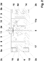
- Fig. 2
- eine Schnittdarstellung im Bereich der Schwenkachse,
- Fig. 3
- eine dreidimensionale Darstellung der am Zugfahrzeug befestigten Anhängerkupplung beim Zusammenwirken mit einer anhängerseitigen Kupplung,
- Fig. 4
- eine Seitenansicht der Darstellung gemäß
Fig. 3 in einer ersten Stellung des Schwenkelements, - Fig. 5
- eine Seitenansicht der Darstellung gemäß
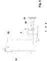
Fig. 3 in einer zweiten Stellung des Schwenkelements, - Fig. 6
- eine Seitenansicht der Anhängerkupplung gemäß einer zweiten Ausgestaltung und
- Fig. 7
- eine Seitenansicht der Anhängerkupplung gemäß einer dritten Ausgestaltung.
- In den
Figuren 1 und2 ist eine Anhängerkupplung 1 für ein Zugfahrzeug dargestellt, die einen Halterungsteil 2 zur Befestigung der Anhängerkupplung 1 am Zugfahrzeug, einen Kugelkopf 3 und einen Niederhalter 4 umfasst. Der Kugelkopf 3 und der Niederhalter 4 sind dabei auf einem U-förmigen Schwenkelement 5 gehaltert, dass um eine Schwenkachse 6 schwenkbar am Halterungsteil 2 befestigt ist. Im dargestellten Ausführungsbeispiel verläuft die Schwenkachse 6 durch den Kugelmittelpunkt 7 des Kugelkopfes 3. Es ist aber in jedem Fall wichtig, dass die Schwenkachse so ausgerichtet ist, dass sie den Kugelkopf 3 zumindest schneidet. Vorzugsweise sollte die Schwenkachse einen Abstand von Kugelmittelpunkt im Bereich von 0 mm +/- 30% des Durchmessers des Kugelkopfes aufweisen. Um ein Ausschwenken des Kugelkopfes 3 bei einer Zugbelastung vollständig zu vermeiden, ist es jedoch zweckmäßig, wenn die Schwenkachse im Wesentlichen durch den Kugelmittelpunkt 7 verläuft, wie dies beim dargestellten Ausführungsbeispiel der Fall ist. - Zum Ankuppeln eines Anhängers ist es erforderlich, dass der Niederhalter 4 abgenommen oder weggeschwenkt wird. Bezüglich des Niederhalters kann der Fachmann auf herkömmliche Lösungen zurückgreifen. Im dargestellten Ausführungsbeispiel wird der Niederhalter 4 in einen Sockel 8 eingesteckt und über einen Bolzen 9 drehfest in der eingesteckten Stellung gesichert. Der Niederhalter 4 weist in der in den
Figuren 1 und2 gezeigten, eingesteckten Stellung einen Arm 10 auf, der bis über den Kugelkopf 3 ragt und über dem Kugelmittelpunkt 7 eine Einstellschraube 11 haltert, welche durch den Arm 10 auf die dem Kugelkopf 2 zugewandte Seite des Armes 10 hindurchragt. Die Einstellschraube weist ein dem Kugelkopf 3 zugewandtes Ende 11a auf, wobei sich der Abstand zwischen dem Ende 11a der Einstellschraube 11 und dem Kugelkopf 3 durch Drehen der Einstellschraube 11 einstellen lässt. Die Stellung des unteren Endes 11a der Einstellschraube 11 bezüglich des Kugelkopfes 3 kann zudem über eine Feststellmutter 12 fixiert werden. Der Abstand wird dabei relativ klein gewählt, sodass sich bei einer eingehängten, anhängerseitigen Kupplungspfanne ein Abstand zur Kupplungspfanne von beispielsweise 1 +/- 0,5 mm ergibt. Der Niederhalter soll dabei verhindern, dass sich die Kupplungspfanne des Anhängers in ungewollter Weise vom Kugelkopf 3 löst. Andererseits muss der Abstand ausreichend groß sein, um zu verhindern, dass der Niederhalter bzw. insbesondere das untere Ende 11a der Einstellschraube 11 bei Kurvenfahrten oder Geländeunebenheiten mit dem anhängerseitigen Kupplungsteil in Kontakt kommt und unnötig verschleißt. - Der Halterungsteil 2 ist im dargestellten Ausführungsbeispiel ebenfalls U-förmig ausgebildet und weist zwei seitliche Schenkel 2a, 2b auf, die jeweils eine Lagerstelle 13, 14 bilden. Das U-förmige Schwenkelement 5 weist ebenfalls zwei seitliche Schenkel 5a, 5b auf, die jeweils mit einem Achsstummel 15c bzw. 15d versehen sind, die in den Lagerstellen 13, 14 am Halterungsteil 2 schwenkbeweglich um die Schwenkachse 6 gehaltert sind. Das Schwenkelement 5, der Kugelkopf 3 und der Sockel 8 können dabei beispielsweise als einstückiges Metallteil gefertigt sein.
- Um die Montage des Schwenkelements 5 am Halterungsteil 2 zu ermöglichen, ist im dargestellten Ausführungsbeispiel im Bereich der Lagerstellen 13, 14 eine nach oben offene Nut 2c bzw. 2d vorgesehen, über welche die Achsstummel 5c, 5d in die Lagerstellen 13 bzw. 14 eingeführt werden können. Zur Sicherung des Schwenkelements 5 am Halterungsteil 2 sind oberhalb der Achsstummel 5c, 5d verschraubbare Sicherungsbolzen 15, 16 angebracht. Im Rahmen der Erfindung sind aber auch andere Lösungen denkbar, so kann die Schwenkachse beispielsweise durch zwei kurze Steckachsen gebildet werden. Eine zweiteilige Ausbildung des Halterungsteils wäre auch denkbar.
- Die oben anhand der Zeichnung beschriebene Ausführungsbeispiel ermöglicht ein Schwenken des Schwenkelements 5 um die Schwenkachse 6, wobei der fest mit dem Schwenkelement verbundene Kugelkopf 3 sowie der Niederhalter 4 als Einheit mitschwenken.
- Der Halterungsteil 2 wird über geeignete Kopplungsmittel, beispielsweise Schrauben 17, drehfest am Zugfahrzeug befestigt. Hierbei kommen prinzipiell alle im Stand der Technik bekannten Befestigungsarten von Anhängerkupplungen an Zugfahrzeugen in Betracht. In der dreidimensionalen Darstellung gemäß
Fig. 3 ist ein herkömmlicher Anhängebock 18 eines Zugfahrzeugs, insbesondere eines Traktors dargestellt. Dieser Anhängebock 18 weist zwei gegenüberliegende Aufnahmeschiene 19, 20 auf, in denen eine Tragplatte 21 verschoben und in einer gewünschten Höhe fixiert werden kann. Die Anhängerkupplung 1 ist dabei mit dieser Tragplatte 21 verschraubt und kann auf diese Weise in der gewünschten Höhe von Boden drehfest am Zugfahrzeug befestigt werden. In dieser Darstellung ist auch die am Kugelkopf 3 eingehängte anhängerseitige Kupplung 22 mit der Kupplungspfanne 23 dargestellt. - In den
Figuren 4 und5 sind zwei unterschiedliche Fahrsituationen veranschaulicht.Fig. 4 zeigt eine Situation, bei der sich das Zugfahrzeug und der Anhänger auf einer ebenen oder gleichmäßig geneigten Oberfläche befinden. Hier nimmt das Schwenkelement 5 bzw. der Kugelkopf und Niederhalter 4 eine Stellung ein, welche mit der Ausrichtung einer herkömmlichen Anhängerkupplung vergleichbar ist. In der Fahrsituation gemäßFig. 5 durchfährt das Gespann aus Zugfahrzeug und Anhänger gerade eine Mulde, bei der das Zugfahrzeug dem tiefsten Punkt schon überwunden hat, während der Anhänger noch in die Mulde hinfährt. InFig. 4 beträgt der Winkel α zwischen der Zugrichtung 25 der zugfahrzeugseitigen Anhängerkupplung 1 und der Längsrichtung 26 der anhängerseitigen Kupplung 22 etwa 180°. Beim Durchfahren der Mulde verkleinert sich dieser Winkel um beispielsweise 20° bis 30°. Es ergibt sich dann ein Winkel β von beispielsweise 150°. Bei herkömmlichen Anhängerkupplungen besteht in dieser Fahrsituation die Gefahr, dass die anhängerseitige Kupplung 22 beim Hochschwenken mit dem Niederhalter 4 in Kontakt kommt und diesen dabei verbiegt oder gar zerstört. - Erfindungsgemäß erfolgt jedoch in dieser Fahrsituation ein Verschwenken der aus Kugelkopf 3 und Niederhalter 4 bestehenden Einheit durch Verschwenken des Schwenkelements 5 um die Schwenkachse 6, wie dies aus
Fig. 5 hervorgeht. Eine Kollision der anhängerseitigen Kupplung 22 mit dem Niederhalter 4 kann auf diese Weise verhindert werden. - Die erfindungsgemäße Anhängerkupplung ist insbesondere für landwirtschaftliche oder forstwirtschaftliche Fahrzeuge, aber auch für alle anderen Fahrzeuge besonders geeignet, wo es durch die Art des Untergrundes zu extremen Stellungen zwischen der Anhängerkupplung 1 des Zugfahrzeuges und der anhängerseitigen Kupplung 22 kommen kann.
- Bei dem bisher beschriebenen Ausführungsbeispiel wurde die Schwenkbeweglichkeit der aus Kugelkopf 3 und Niederhalter 4 gebildeten Einheit um die Schwenkachse 6 über zylindrische Achsstummel 5c, 5d realisiert. Im Rahmen der Erfindung ist es aber auch denkbar, dass die Achsstummel eine nicht kreisförmige Querschnittsform aufweisen.
Fig. 6 zeigt eine Seitenansicht einer Anhängerkupplung gemäß einem zweiten Ausführungsbeispiel, bei dem ein Achsstummel 5'c in einer Aussparung 5'e eines Schenkels 5'a gelagert ist und der Querschnitt des Achsstummels 5'c trapezförmig ausgebildet ist. Dies hat zur Folge, dass ein Schwenken bzw. Kippen nicht sofort bei jedem von 180° abweichenden Winkel α erfolgt. Es ist vielmehr erst ein gewisses Kippmoment zu überwinden, bevor die aus Kugelkopf und Niederhalter gebildete Einheit in die eine oder andere Richtung schwenkt. Eine der beiden maximal gekippten Stellungen ist dabei gestrichelt dargestellt. -
Fig. 7 zeigt eine dritte Ausgestaltung, bei welcher ein Achsstummel 5"c flach bzw. im Querschnitt rechteckförmig ausgebildet ist. Die Aussparung 5"e sieht dabei in einem Mittelbereich eine kleine Erhöhung 5"f vor, sodass der Achsstummel in begrenztem Umfang auf dieser Erhöhung 5"f schwenken kann. - Im ersten Ausführungsbeispiel weisen die Schenkel 5a, 5b des Halterungselements Nuten 5c, 5d auf, um das Schwenkelement einhängen zu können. Ist wäre aber auch denkbar, dass die Aussparung für die Achsstummel durch eine geschlossene Kontur gebildet wird und die Montage durch eine zweiteilige Ausführung des Halterungsteils realisiert wird.
- Die Ausführungen gemäß den
Figuren 6 und 7 haben den Vorteil, dass das Schwenkelement auch dann stabil in der waagerechten Lage bleibt, wenn sich die Drehachse nicht genau in der Kugelmitte befindet. Selbstverständlich sind im Rahmen der Erfindung auch noch viele weitere Varianten denkbar, die man nach diesem Konstruktionsprinzip aufbauen könnte.
Claims (12)
- Anhängerkupplung (1) mit einem Halterungsteil (2) zur Befestigung der Anhängerkupplung (1) an einem Zugfahrzeug, einem Kugelkopf (3) und einem Niederhalter (4),
dadurch gekennzeichnet, dass der Kugelkopf (3) und der Niederhalter (4) eine Einheit bilden, die um eine Schwenkachse (6) schwenkbar mit dem Halterungsteil (2) gekoppelt ist, wobei die Schwenkachse (6) so ausgerichtet ist, dass sie den Kugelkopf (3) schneidet. - Anhängerkupplung (1) nach Anspruch 1, dadurch gekennzeichnet, dass die Schwenkachse (6) in einem am Zugfahrzeug befestigten Zustand der Anhängerkupplung (1) parallel zu einer Hinterachse des Zugfahrzeugs ausgerichtet ist.
- Anhängerkupplung (1) nach Anspruch 1, dadurch gekennzeichnet, dass der Kugelkopf (3) und der Niederhalter (4) auf einem Schwenkelement (5) gehaltert sind, das um die Schwenkachse (6) schwenkbar am Halterungsteil (2) befestigt ist.
- Anhängerkupplung (1) nach Anspruch 1, dadurch gekennzeichnet, dass der Kugelkopf (3) einen Kugelmittelpunkt (7) vorsieht und die Schwenkachse (6) einen Abstand vom Kugelmittelpunkt (7) im Bereich von 0 mm +/- 30% des Durchmessers des Kugelkopfes (3) aufweist.
- Anhängerkupplung (1) nach Anspruch 1, dadurch gekennzeichnet, dass der Kugelkopf (3) einen Kugelmittelpunkt (7) aufweist und die Schwenkachse (6) durch den Kugelmittelpunkt (7) verläuft.
- Anhängerkupplung (1) nach Anspruch 3, dadurch gekennzeichnet, dass der Halterungsteil (2) zwei beabstandete Lagerstellen (13, 14) zur schwenkbaren Lagerung des Schwenkelements (5) aufweist, wobei der Abstand der beiden Lagerstellen (13, 14) im Bereich des 1,1-fachen bis 10-fachen Durchmessers des Kugelkopfes (3) liegt.
- Anhängerkupplung (1) nach Anspruch 1, dadurch gekennzeichnet, dass der Halterungsteil (2) über Kopplungsmittel (17) drehfesten am Zugfahrzeugs befestigbar ist.
- Anhängerkupplung (1) nach Anspruch 1, dadurch gekennzeichnet, dass die Anhängerkupplung (1) für eine Stützlast von wenigstens 1.00 bis 4.000 kg und mehr ausgelegt ist.
- Anhängerkupplung (1) nach Anspruch 1, dadurch gekennzeichnet, dass die Anhängerkupplung (1) für eine Anhängelast von mehr 3.500 kg und mehr ausgelegt ist.
- Anhängerkupplung (1) nach Anspruch 1, dadurch gekennzeichnet, dass der Kugelkopf (3) einen Durchmesser von 50 mm bis 120 mm aufweist.
- Anhängerkupplung (1) nach Anspruch 3, dadurch gekennzeichnet, dass der Halterungsteil (2) U-förmig mit zwei seitlichen Schenkeln (2a, 2b) ausgebildet ist und das Schwenkelement (5) im Bereich der seitlichen Schenkel (2a, 2b) verschwenkbar am Halterungsteil (2) angekoppelt ist.
- Anhängerkupplung (1) nach Anspruch 3, dadurch gekennzeichnet, dass das Schwenkelement (5) U-förmig mit zwei seitlichen Schenkeln (5a, 5b) ausgebildet ist und das Schwenkelement (5) im Bereich seiner seitlichen Schenkel (5a, 5b) verschwenkbar am Halterungsteil (2) angekoppelt ist.
Applications Claiming Priority (1)
| Application Number | Priority Date | Filing Date | Title |
|---|---|---|---|
| DE102018132070.1A DE102018132070B4 (de) | 2018-12-13 | 2018-12-13 | Anhängerkupplung |
Publications (2)
| Publication Number | Publication Date |
|---|---|
| EP3666558A1 true EP3666558A1 (de) | 2020-06-17 |
| EP3666558B1 EP3666558B1 (de) | 2021-11-24 |
Family
ID=68382144
Family Applications (1)
| Application Number | Title | Priority Date | Filing Date |
|---|---|---|---|
| EP19204788.4A Active EP3666558B1 (de) | 2018-12-13 | 2019-10-23 | Anhängerkupplung |
Country Status (2)
| Country | Link |
|---|---|
| EP (1) | EP3666558B1 (de) |
| DE (1) | DE102018132070B4 (de) |
Citations (5)
| Publication number | Priority date | Publication date | Assignee | Title |
|---|---|---|---|---|
| DE20318531U1 (de) * | 2003-11-05 | 2004-03-04 | Cramer Kupplung Gmbh & Co. Kg | Anhängekupplung |
| EP1564033A1 (de) * | 2004-02-13 | 2005-08-17 | Josef Scharmüller | Kupplungskörper |
| US20060055151A1 (en) * | 2004-09-14 | 2006-03-16 | Forrister John J | Towing apparatuses |
| DE202005017374U1 (de) * | 2005-11-05 | 2006-03-23 | Sauermann, Hans | Anhängerkupplung für ein Zugfahrzeug, insbesondere für einen Ackerschlepper |
| DE202013008659U1 (de) * | 2013-10-01 | 2015-01-07 | Hans Sauermann | Höhenverstellbare Anhängerkupplung |
Family Cites Families (2)
| Publication number | Priority date | Publication date | Assignee | Title |
|---|---|---|---|---|
| DE202011101498U1 (de) | 2011-06-03 | 2011-10-20 | Dieter Engel | Ackerschiene |
| DE102013211516A1 (de) | 2013-06-19 | 2014-12-24 | Deere & Company | Anhängevorrichtung |
-
2018
- 2018-12-13 DE DE102018132070.1A patent/DE102018132070B4/de active Active
-
2019
- 2019-10-23 EP EP19204788.4A patent/EP3666558B1/de active Active
Patent Citations (5)
| Publication number | Priority date | Publication date | Assignee | Title |
|---|---|---|---|---|
| DE20318531U1 (de) * | 2003-11-05 | 2004-03-04 | Cramer Kupplung Gmbh & Co. Kg | Anhängekupplung |
| EP1564033A1 (de) * | 2004-02-13 | 2005-08-17 | Josef Scharmüller | Kupplungskörper |
| US20060055151A1 (en) * | 2004-09-14 | 2006-03-16 | Forrister John J | Towing apparatuses |
| DE202005017374U1 (de) * | 2005-11-05 | 2006-03-23 | Sauermann, Hans | Anhängerkupplung für ein Zugfahrzeug, insbesondere für einen Ackerschlepper |
| DE202013008659U1 (de) * | 2013-10-01 | 2015-01-07 | Hans Sauermann | Höhenverstellbare Anhängerkupplung |
Also Published As
| Publication number | Publication date |
|---|---|
| EP3666558B1 (de) | 2021-11-24 |
| DE102018132070B4 (de) | 2021-10-14 |
| DE102018132070A1 (de) | 2020-06-18 |
Similar Documents
| Publication | Publication Date | Title |
|---|---|---|
| AT507665B1 (de) | Anhängerkupplung | |
| EP2556736B1 (de) | Längenveränderliche Hubstrebe | |
| EP1216856B1 (de) | Anhängevorrichtung für ein Arbeitsfahrzeug | |
| DE102011055350A1 (de) | Unterfahrschutz zur Anbringung am Heck eines Lastkraftwagens | |
| DE3316128C2 (de) | ||
| EP2457752B1 (de) | Kupplungsvorrichtung und Anhängevorrichtung für Zugfahrzeuge | |
| EP3143861A1 (de) | Landwirtschaftliches mähwerk und zuggespann und verfahren zum betreiben des mähwerks | |
| EP2660082B1 (de) | Anhängekupplung mit einem Schraub-Befestigungselement | |
| EP3666558B1 (de) | Anhängerkupplung | |
| AT526904B1 (de) | Adapter zum Anbau eines Anbaugerätes an ein Trägerfahrzeug | |
| DE102018108079A1 (de) | Lenkeranordnung für einen Dreipunkt-Kraftheber eines Traktors oder einer sonstigen landwirtschaftlichen Arbeitsmaschine sowie Dreipunkt-Kraftheber | |
| EP1236590A1 (de) | Anhängerkupplung | |
| DE102010053083A1 (de) | Sattelkupplung mit einstellbarer Höhe | |
| EP3392067A1 (de) | Kopplungseinrichtung eines routenzugs | |
| EP2904888B1 (de) | Geräteträgervorrichtung für landwirtschaftliche Geräte | |
| EP1710100A1 (de) | Schwerlastkupplung | |
| DE19609910C2 (de) | Fahrradanhänger-Kupplung | |
| WO2020169327A1 (de) | Kopplungseinrichtung eines routenzugs | |
| EP1559593A2 (de) | Anhängesystem zur Verbindung eines Zugfahrzeuges mit einem Anhänger | |
| DE102004012483B4 (de) | Kupplungseinrichtung zum Verbinden eines Zugfahrzeuges mit einem Anhänger | |
| DE1582169A1 (de) | Erntebergungsmaschine,insbesondere Feldhaecksler | |
| EP0155654A2 (de) | Landwirtschaftliches Arbeitsgerät | |
| EP4696526A1 (de) | Kupplungsvorrichtung und kupplungssystem zum kuppeln eines anhängers an ein zugfahrzeug | |
| DE202024101382U1 (de) | Rückewagen-Arbeitsstation sowie Schutzgitter für eine derartige Rückewagen-Arbeitsstation | |
| EP2892314B1 (de) | Drehpflug |
Legal Events
| Date | Code | Title | Description |
|---|---|---|---|
| PUAI | Public reference made under article 153(3) epc to a published international application that has entered the european phase |
Free format text: ORIGINAL CODE: 0009012 |
|
| STAA | Information on the status of an ep patent application or granted ep patent |
Free format text: STATUS: THE APPLICATION HAS BEEN PUBLISHED |
|
| AK | Designated contracting states |
Kind code of ref document: A1 Designated state(s): AL AT BE BG CH CY CZ DE DK EE ES FI FR GB GR HR HU IE IS IT LI LT LU LV MC MK MT NL NO PL PT RO RS SE SI SK SM TR |
|
| AX | Request for extension of the european patent |
Extension state: BA ME |
|
| STAA | Information on the status of an ep patent application or granted ep patent |
Free format text: STATUS: REQUEST FOR EXAMINATION WAS MADE |
|
| 17P | Request for examination filed |
Effective date: 20201216 |
|
| RBV | Designated contracting states (corrected) |
Designated state(s): AL AT BE BG CH CY CZ DE DK EE ES FI FR GB GR HR HU IE IS IT LI LT LU LV MC MK MT NL NO PL PT RO RS SE SI SK SM TR |
|
| GRAP | Despatch of communication of intention to grant a patent |
Free format text: ORIGINAL CODE: EPIDOSNIGR1 |
|
| RIC1 | Information provided on ipc code assigned before grant |
Ipc: B60D 1/06 20060101AFI20210602BHEP Ipc: B60D 1/58 20060101ALI20210602BHEP Ipc: B60D 1/28 20060101ALN20210602BHEP |
|
| STAA | Information on the status of an ep patent application or granted ep patent |
Free format text: STATUS: GRANT OF PATENT IS INTENDED |
|
| INTG | Intention to grant announced |
Effective date: 20210708 |
|
| GRAS | Grant fee paid |
Free format text: ORIGINAL CODE: EPIDOSNIGR3 |
|
| GRAA | (expected) grant |
Free format text: ORIGINAL CODE: 0009210 |
|
| STAA | Information on the status of an ep patent application or granted ep patent |
Free format text: STATUS: THE PATENT HAS BEEN GRANTED |
|
| AK | Designated contracting states |
Kind code of ref document: B1 Designated state(s): AL AT BE BG CH CY CZ DE DK EE ES FI FR GB GR HR HU IE IS IT LI LT LU LV MC MK MT NL NO PL PT RO RS SE SI SK SM TR |
|
| REG | Reference to a national code |
Ref country code: GB Ref legal event code: FG4D Free format text: NOT ENGLISH |
|
| REG | Reference to a national code |
Ref country code: DE Ref legal event code: R096 Ref document number: 502019002835 Country of ref document: DE |
|
| REG | Reference to a national code |
Ref country code: AT Ref legal event code: REF Ref document number: 1449598 Country of ref document: AT Kind code of ref document: T Effective date: 20211215 |
|
| REG | Reference to a national code |
Ref country code: IE Ref legal event code: FG4D Free format text: LANGUAGE OF EP DOCUMENT: GERMAN |
|
| REG | Reference to a national code |
Ref country code: LT Ref legal event code: MG9D |
|
| REG | Reference to a national code |
Ref country code: NL Ref legal event code: MP Effective date: 20211124 |
|
| PG25 | Lapsed in a contracting state [announced via postgrant information from national office to epo] |
Ref country code: RS Free format text: LAPSE BECAUSE OF FAILURE TO SUBMIT A TRANSLATION OF THE DESCRIPTION OR TO PAY THE FEE WITHIN THE PRESCRIBED TIME-LIMIT Effective date: 20211124 Ref country code: LT Free format text: LAPSE BECAUSE OF FAILURE TO SUBMIT A TRANSLATION OF THE DESCRIPTION OR TO PAY THE FEE WITHIN THE PRESCRIBED TIME-LIMIT Effective date: 20211124 Ref country code: FI Free format text: LAPSE BECAUSE OF FAILURE TO SUBMIT A TRANSLATION OF THE DESCRIPTION OR TO PAY THE FEE WITHIN THE PRESCRIBED TIME-LIMIT Effective date: 20211124 Ref country code: BG Free format text: LAPSE BECAUSE OF FAILURE TO SUBMIT A TRANSLATION OF THE DESCRIPTION OR TO PAY THE FEE WITHIN THE PRESCRIBED TIME-LIMIT Effective date: 20220224 |
|
| PG25 | Lapsed in a contracting state [announced via postgrant information from national office to epo] |
Ref country code: IS Free format text: LAPSE BECAUSE OF FAILURE TO SUBMIT A TRANSLATION OF THE DESCRIPTION OR TO PAY THE FEE WITHIN THE PRESCRIBED TIME-LIMIT Effective date: 20220324 Ref country code: SE Free format text: LAPSE BECAUSE OF FAILURE TO SUBMIT A TRANSLATION OF THE DESCRIPTION OR TO PAY THE FEE WITHIN THE PRESCRIBED TIME-LIMIT Effective date: 20211124 Ref country code: PT Free format text: LAPSE BECAUSE OF FAILURE TO SUBMIT A TRANSLATION OF THE DESCRIPTION OR TO PAY THE FEE WITHIN THE PRESCRIBED TIME-LIMIT Effective date: 20220324 Ref country code: PL Free format text: LAPSE BECAUSE OF FAILURE TO SUBMIT A TRANSLATION OF THE DESCRIPTION OR TO PAY THE FEE WITHIN THE PRESCRIBED TIME-LIMIT Effective date: 20211124 Ref country code: NO Free format text: LAPSE BECAUSE OF FAILURE TO SUBMIT A TRANSLATION OF THE DESCRIPTION OR TO PAY THE FEE WITHIN THE PRESCRIBED TIME-LIMIT Effective date: 20220224 Ref country code: NL Free format text: LAPSE BECAUSE OF FAILURE TO SUBMIT A TRANSLATION OF THE DESCRIPTION OR TO PAY THE FEE WITHIN THE PRESCRIBED TIME-LIMIT Effective date: 20211124 Ref country code: LV Free format text: LAPSE BECAUSE OF FAILURE TO SUBMIT A TRANSLATION OF THE DESCRIPTION OR TO PAY THE FEE WITHIN THE PRESCRIBED TIME-LIMIT Effective date: 20211124 Ref country code: HR Free format text: LAPSE BECAUSE OF FAILURE TO SUBMIT A TRANSLATION OF THE DESCRIPTION OR TO PAY THE FEE WITHIN THE PRESCRIBED TIME-LIMIT Effective date: 20211124 Ref country code: GR Free format text: LAPSE BECAUSE OF FAILURE TO SUBMIT A TRANSLATION OF THE DESCRIPTION OR TO PAY THE FEE WITHIN THE PRESCRIBED TIME-LIMIT Effective date: 20220225 Ref country code: ES Free format text: LAPSE BECAUSE OF FAILURE TO SUBMIT A TRANSLATION OF THE DESCRIPTION OR TO PAY THE FEE WITHIN THE PRESCRIBED TIME-LIMIT Effective date: 20211124 |
|
| PG25 | Lapsed in a contracting state [announced via postgrant information from national office to epo] |
Ref country code: SM Free format text: LAPSE BECAUSE OF FAILURE TO SUBMIT A TRANSLATION OF THE DESCRIPTION OR TO PAY THE FEE WITHIN THE PRESCRIBED TIME-LIMIT Effective date: 20211124 Ref country code: SK Free format text: LAPSE BECAUSE OF FAILURE TO SUBMIT A TRANSLATION OF THE DESCRIPTION OR TO PAY THE FEE WITHIN THE PRESCRIBED TIME-LIMIT Effective date: 20211124 Ref country code: RO Free format text: LAPSE BECAUSE OF FAILURE TO SUBMIT A TRANSLATION OF THE DESCRIPTION OR TO PAY THE FEE WITHIN THE PRESCRIBED TIME-LIMIT Effective date: 20211124 Ref country code: EE Free format text: LAPSE BECAUSE OF FAILURE TO SUBMIT A TRANSLATION OF THE DESCRIPTION OR TO PAY THE FEE WITHIN THE PRESCRIBED TIME-LIMIT Effective date: 20211124 Ref country code: DK Free format text: LAPSE BECAUSE OF FAILURE TO SUBMIT A TRANSLATION OF THE DESCRIPTION OR TO PAY THE FEE WITHIN THE PRESCRIBED TIME-LIMIT Effective date: 20211124 Ref country code: CZ Free format text: LAPSE BECAUSE OF FAILURE TO SUBMIT A TRANSLATION OF THE DESCRIPTION OR TO PAY THE FEE WITHIN THE PRESCRIBED TIME-LIMIT Effective date: 20211124 |
|
| REG | Reference to a national code |
Ref country code: DE Ref legal event code: R097 Ref document number: 502019002835 Country of ref document: DE |
|
| PLBE | No opposition filed within time limit |
Free format text: ORIGINAL CODE: 0009261 |
|
| STAA | Information on the status of an ep patent application or granted ep patent |
Free format text: STATUS: NO OPPOSITION FILED WITHIN TIME LIMIT |
|
| PG25 | Lapsed in a contracting state [announced via postgrant information from national office to epo] |
Ref country code: AL Free format text: LAPSE BECAUSE OF FAILURE TO SUBMIT A TRANSLATION OF THE DESCRIPTION OR TO PAY THE FEE WITHIN THE PRESCRIBED TIME-LIMIT Effective date: 20211124 |
|
| 26N | No opposition filed |
Effective date: 20220825 |
|
| PG25 | Lapsed in a contracting state [announced via postgrant information from national office to epo] |
Ref country code: SI Free format text: LAPSE BECAUSE OF FAILURE TO SUBMIT A TRANSLATION OF THE DESCRIPTION OR TO PAY THE FEE WITHIN THE PRESCRIBED TIME-LIMIT Effective date: 20211124 |
|
| PG25 | Lapsed in a contracting state [announced via postgrant information from national office to epo] |
Ref country code: MC Free format text: LAPSE BECAUSE OF FAILURE TO SUBMIT A TRANSLATION OF THE DESCRIPTION OR TO PAY THE FEE WITHIN THE PRESCRIBED TIME-LIMIT Effective date: 20211124 Ref country code: IT Free format text: LAPSE BECAUSE OF FAILURE TO SUBMIT A TRANSLATION OF THE DESCRIPTION OR TO PAY THE FEE WITHIN THE PRESCRIBED TIME-LIMIT Effective date: 20211124 |
|
| REG | Reference to a national code |
Ref country code: BE Ref legal event code: MM Effective date: 20221031 |
|
| PG25 | Lapsed in a contracting state [announced via postgrant information from national office to epo] |
Ref country code: LU Free format text: LAPSE BECAUSE OF NON-PAYMENT OF DUE FEES Effective date: 20221023 |
|
| PG25 | Lapsed in a contracting state [announced via postgrant information from national office to epo] |
Ref country code: BE Free format text: LAPSE BECAUSE OF NON-PAYMENT OF DUE FEES Effective date: 20221031 |
|
| PG25 | Lapsed in a contracting state [announced via postgrant information from national office to epo] |
Ref country code: IE Free format text: LAPSE BECAUSE OF NON-PAYMENT OF DUE FEES Effective date: 20221023 |
|
| PG25 | Lapsed in a contracting state [announced via postgrant information from national office to epo] |
Ref country code: HU Free format text: LAPSE BECAUSE OF FAILURE TO SUBMIT A TRANSLATION OF THE DESCRIPTION OR TO PAY THE FEE WITHIN THE PRESCRIBED TIME-LIMIT; INVALID AB INITIO Effective date: 20191023 |
|
| PG25 | Lapsed in a contracting state [announced via postgrant information from national office to epo] |
Ref country code: CY Free format text: LAPSE BECAUSE OF FAILURE TO SUBMIT A TRANSLATION OF THE DESCRIPTION OR TO PAY THE FEE WITHIN THE PRESCRIBED TIME-LIMIT Effective date: 20211124 |
|
| PG25 | Lapsed in a contracting state [announced via postgrant information from national office to epo] |
Ref country code: MK Free format text: LAPSE BECAUSE OF FAILURE TO SUBMIT A TRANSLATION OF THE DESCRIPTION OR TO PAY THE FEE WITHIN THE PRESCRIBED TIME-LIMIT Effective date: 20211124 |
|
| GBPC | Gb: european patent ceased through non-payment of renewal fee |
Effective date: 20231023 |
|
| PG25 | Lapsed in a contracting state [announced via postgrant information from national office to epo] |
Ref country code: GB Free format text: LAPSE BECAUSE OF NON-PAYMENT OF DUE FEES Effective date: 20231023 |
|
| PG25 | Lapsed in a contracting state [announced via postgrant information from national office to epo] |
Ref country code: GB Free format text: LAPSE BECAUSE OF NON-PAYMENT OF DUE FEES Effective date: 20231023 |
|
| PG25 | Lapsed in a contracting state [announced via postgrant information from national office to epo] |
Ref country code: MT Free format text: LAPSE BECAUSE OF FAILURE TO SUBMIT A TRANSLATION OF THE DESCRIPTION OR TO PAY THE FEE WITHIN THE PRESCRIBED TIME-LIMIT Effective date: 20211124 |
|
| REG | Reference to a national code |
Ref country code: CH Ref legal event code: U11 Free format text: ST27 STATUS EVENT CODE: U-0-0-U10-U11 (AS PROVIDED BY THE NATIONAL OFFICE) Effective date: 20251101 |
|
| PG25 | Lapsed in a contracting state [announced via postgrant information from national office to epo] |
Ref country code: TR Free format text: LAPSE BECAUSE OF FAILURE TO SUBMIT A TRANSLATION OF THE DESCRIPTION OR TO PAY THE FEE WITHIN THE PRESCRIBED TIME-LIMIT Effective date: 20211124 |
|
| PGFP | Annual fee paid to national office [announced via postgrant information from national office to epo] |
Ref country code: DE Payment date: 20251001 Year of fee payment: 7 |
|
| PGFP | Annual fee paid to national office [announced via postgrant information from national office to epo] |
Ref country code: AT Payment date: 20251022 Year of fee payment: 7 |
|
| PGFP | Annual fee paid to national office [announced via postgrant information from national office to epo] |
Ref country code: FR Payment date: 20251030 Year of fee payment: 7 |
|
| PGFP | Annual fee paid to national office [announced via postgrant information from national office to epo] |
Ref country code: CH Payment date: 20251101 Year of fee payment: 7 |