EP3666532A1 - A method for alleviating mechanical imprints on a recording medium - Google Patents
A method for alleviating mechanical imprints on a recording medium Download PDFInfo
- Publication number
- EP3666532A1 EP3666532A1 EP18211731.7A EP18211731A EP3666532A1 EP 3666532 A1 EP3666532 A1 EP 3666532A1 EP 18211731 A EP18211731 A EP 18211731A EP 3666532 A1 EP3666532 A1 EP 3666532A1
- Authority
- EP
- European Patent Office
- Prior art keywords
- recording medium
- mechanical
- onto
- coating
- imprints
- Prior art date
- Legal status (The legal status is an assumption and is not a legal conclusion. Google has not performed a legal analysis and makes no representation as to the accuracy of the status listed.)
- Withdrawn
Links
Images

Classifications
-
- B—PERFORMING OPERATIONS; TRANSPORTING
- B41—PRINTING; LINING MACHINES; TYPEWRITERS; STAMPS
- B41J—TYPEWRITERS; SELECTIVE PRINTING MECHANISMS, i.e. MECHANISMS PRINTING OTHERWISE THAN FROM A FORME; CORRECTION OF TYPOGRAPHICAL ERRORS
- B41J11/00—Devices or arrangements of selective printing mechanisms, e.g. ink-jet printers or thermal printers, for supporting or handling copy material in sheet or web form
- B41J11/0015—Devices or arrangements of selective printing mechanisms, e.g. ink-jet printers or thermal printers, for supporting or handling copy material in sheet or web form for treating before, during or after printing or for uniform coating or laminating the copy material before or after printing
-
- B—PERFORMING OPERATIONS; TRANSPORTING
- B41—PRINTING; LINING MACHINES; TYPEWRITERS; STAMPS
- B41J—TYPEWRITERS; SELECTIVE PRINTING MECHANISMS, i.e. MECHANISMS PRINTING OTHERWISE THAN FROM A FORME; CORRECTION OF TYPOGRAPHICAL ERRORS
- B41J2/00—Typewriters or selective printing mechanisms characterised by the printing or marking process for which they are designed
- B41J2/005—Typewriters or selective printing mechanisms characterised by the printing or marking process for which they are designed characterised by bringing liquid or particles selectively into contact with a printing material
- B41J2/01—Ink jet
- B41J2/21—Ink jet for multi-colour printing
- B41J2/2107—Ink jet for multi-colour printing characterised by the ink properties
- B41J2/2114—Ejecting specialized liquids, e.g. transparent or processing liquids
- B41J2/2117—Ejecting white liquids
-
- B—PERFORMING OPERATIONS; TRANSPORTING
- B41—PRINTING; LINING MACHINES; TYPEWRITERS; STAMPS
- B41J—TYPEWRITERS; SELECTIVE PRINTING MECHANISMS, i.e. MECHANISMS PRINTING OTHERWISE THAN FROM A FORME; CORRECTION OF TYPOGRAPHICAL ERRORS
- B41J11/00—Devices or arrangements of selective printing mechanisms, e.g. ink-jet printers or thermal printers, for supporting or handling copy material in sheet or web form
- B41J11/0095—Detecting means for copy material, e.g. for detecting or sensing presence of copy material or its leading or trailing end
-
- B—PERFORMING OPERATIONS; TRANSPORTING
- B41—PRINTING; LINING MACHINES; TYPEWRITERS; STAMPS
- B41J—TYPEWRITERS; SELECTIVE PRINTING MECHANISMS, i.e. MECHANISMS PRINTING OTHERWISE THAN FROM A FORME; CORRECTION OF TYPOGRAPHICAL ERRORS
- B41J2203/00—Embodiments of or processes related to the control of the printing process
- B41J2203/01—Inspecting a printed medium or a medium to be printed using a sensing device
- B41J2203/011—Inspecting the shape or condition, e.g. wrinkled or warped, of a medium to be printed before printing on it
-
- B—PERFORMING OPERATIONS; TRANSPORTING
- B41—PRINTING; LINING MACHINES; TYPEWRITERS; STAMPS
- B41M—PRINTING, DUPLICATING, MARKING, OR COPYING PROCESSES; COLOUR PRINTING
- B41M5/00—Duplicating or marking methods; Sheet materials for use therein
- B41M5/0011—Pre-treatment or treatment during printing of the recording material, e.g. heating, irradiating
Definitions
- the present invention relates to a method for printing an image onto a recording medium wherein mechanic imprints on the recording medium are alleviated. Further, the invention relates to a printer for printing an image onto a recording medium configured for performing such a method.
- a printer or any other machine in which an image is created using an ink a recording medium may be transported through the printer passing, amongst others, one or more printheads for jetting an ink onto the recording medium.
- the recording medium may endure mechanical imprints.
- the recording medium may be transported through the printer using transporting wheels which may leave wheel imprints on the recording medium.
- Other sources of mechanical imprint may be clamps retaining the recording medium in an input or output module of the recording medium or gripping elements for loading the recording medium into the printer.
- the mechanical imprint may reduce the visual quality of the image created by the printer.
- the mechanical imprint may be visible in the image.
- a groove may be visible where the transporting wheels left a wheel imprint.
- the mechanical imprint may be invisible directly but visible indirectly.
- the groove made due to wheel imprint may be shallow enough to be invisible to the naked eye but may be sufficient to result in a different glossiness of the ink printed at the groove compared to the ink printed in an area other than the groove.
- the object of the invention is achieved in a method for printing an image onto a recording medium wherein the method comprises the steps of:
- the method for printing an image onto a recording medium further comprises the step of selectively applying a second amount of a first coating onto the recording medium.
- a second amount of a first coating may be applied on top of the first amount of the first coating and the rest of the recording medium, i.e. the entire recording medium, to create an even surface with the same surface properties over the entire recording medium.
- the second amount of a first coating may also be applied image wise to cover all areas where ink will be jetted to form an image and thus creating an even surface with the same surface properties where the ink will be jetted.
- the second amount of a first coating may also be applied in a specific pattern in accordance with a desired glossiness pattern across the image.
- the second amount of the first coating may introduce desired changes to the printed image such as specific glossiness to certain image elements.
- the area of mechanical imprint is determined by scanning the recording medium.
- the one or more areas of mechanical imprints may be scanned using an optical sensor.
- a CCD or CMOS image sensor may be used in combination with a laser source to create a three-dimensional height map of the surface of the recording medium.
- a first amount of a first coating may be applied onto the areas of mechanical imprint determined by scanning the recording medium.
- the area of mechanical imprinting is determined by pre-determining an area wherein mechanical load may be induced onto the recording medium.
- the recording medium may endure a mechanical load by for instance transporting wheels, clamps and grips with a specific, known, pressure leaving a pre-determined area and known depth of mechanical imprint on the recording medium.
- a first amount of a first coating may be applied onto pre-determined areas where the recording medium is prone to mechanical load leading to known mechanical imprints.
- a printer for printing an image onto a recording medium wherein the printer comprises:
- Fig. 1A shows an ink jet printing assembly 3.
- the ink jet printing assembly 3 comprises supporting means for supporting an image receiving medium 2.
- the supporting means are shown in Fig. 1A as a flat surface 1, but alternatively, the supporting means may be a platen, for example a rotatable drum that is rotatable around an axis.
- the supporting means may be optionally provided with suction holes for holding the image receiving medium in a fixed position with respect to the supporting means.
- the ink jet printing assembly 3 comprises print heads 4a - 4e, mounted on a scanning print carriage 5.
- the scanning print carriage 5 is guided by suitable guiding means 6 to move in reciprocation in the main scanning direction X.
- Each print head 4a - 4e comprises an orifice surface 9, which orifice surface 9 is provided with at least one orifice 8, as is shown in Fig. 1B .
- the print heads 4a - 4e are configured to eject droplets of marking material and/or coating material onto the image receiving medium 2.
- the image receiving medium 2 may be a medium in web or in sheet form and may be composed of e.g. paper, cardboard, label stock, coated paper, plastic or textile. Alternatively, the image receiving medium 2 may also be an intermediate member, endless or not. Examples of endless members, which may be moved cyclically, are a belt or a drum. The image receiving medium 2 is moved in the sub-scanning direction Y over the flat surface 1 along five print heads 4a - 4e provided with a fluid marking material and/or coating material.
- a scanning print carriage 5 carries the five print heads 4a - 4e and may be moved in reciprocation in the main scanning direction X parallel to the platen 1, such as to enable scanning of the image receiving medium 2 in the main scanning direction X. Only five print heads 4a - 4e are depicted for demonstrating the invention. In practice an arbitrary number of print heads may be employed. In any case, at least one print head 4a - 4e per color of marking material and/or coating material is placed on the scanning print carriage 5. For example, for a black-and-white printer, at least one print head 4a - 4e, usually containing black marking material is present. Alternatively, a black-and-white printer may comprise a white marking material, which is to be applied on a black image-receiving medium 2.
- At least one print head 4a - 4e for each of the colors usually black, cyan, magenta and yellow, and for the coating material is present.
- black marking material is used more frequently in comparison to differently colored marking material. Therefore, more print heads 4a - 4e containing black marking material may be provided on the scanning print carriage 5 compared to print heads 4a - 4e containing marking material in any of the other colors.
- the print head 4a - 4e containing black marking material may be larger than any of the print heads 4a - 4e, containing a differently colored marking material.
- the carriage 5 is guided by guiding means 6.
- These guiding means 6 may be a rod as depicted in Fig. 1A . Although only one rod 6 is depicted in Fig. 1A , a plurality of rods may be used to guide the carriage 5 carrying the print heads 4.
- the rod may be driven by suitable driving means (not shown).
- the carriage 5 may be guided by other guiding means, such as an arm being able to move the carriage 5.
- Another alternative is to move the image receiving material 2 in the main scanning direction X.
- Each print head 4a - 4e comprises an orifice surface 9 having at least one orifice 8, in fluid communication with a pressure chamber containing fluid marking material provided in the print head 4a - 4e.
- a number of orifices 8 are arranged in a single linear array parallel to the sub-scanning direction Y, as is shown in Fig. 1B .
- the nozzles may be arranged in the main scanning direction X.
- Eight orifices 8 per print head 4a - 4e are depicted in Fig. 1B , however obviously in a practical embodiment several hundreds of orifices 8 may be provided per print head 4a - 4e, optionally arranged in multiple arrays.
- the respective print heads 4a - 4e are placed parallel to each other.
- the print heads 4a - 4e may be placed such that corresponding orifices 8 of the respective print heads 4a - 4e are positioned in-line in the main scanning direction X.
- a line of image dots in the main scanning direction X may be formed by selectively activating up to four orifices 8, each of them being part of a different print head 4a - 4e.
- This parallel positioning of the print heads 4a - 4e with corresponding in-line placement of the orifices 8 is advantageous to increase productivity and/or improve print quality.
- multiple print heads 4a - 4e may be placed on the print carriage adjacent to each other such that the orifices 8 of the respective print heads 4a - 4e are positioned in a staggered configuration instead of in-line. For instance, this may be done to increase the print resolution or to enlarge the effective print area, which may be addressed in a single scan in the main scanning direction X.
- the image dots are formed by ejecting droplets of marking material from the orifices 8.
- the ink jet printing assembly 3 may further comprise an optical sensor 11.
- a scanning print carriage 12 carries the optical sensor 11 and may be moved in reciprocation in the main scanning direction X parallel to the platen 1, such as to enable scanning of the image receiving medium 2 in the main scanning direction X.
- the optical sensor 11 may be a CCD or CMOS image sensor.
- the optical sensor 11 may also comprise a light source to illuminate the surface of the image receiving medium 2 to enable the CCD or CMOS image sensor to receive a clearer image.
- the light source may be an LED light source or a laser light source.
- the carriage 12 is guided by guiding means 7.
- These guiding means 7 may be a rod as depicted in Fig. 1A . Although only one rod 7 is depicted in Fig. 1A , a plurality of rods may be used to guide the carriage 12 carrying the optical sensor 11.
- the rod 7 may be driven by suitable driving means (not shown).
- the carriage 12 may be guided by other guiding means, such as an arm being able to move the carriage 12.
- the flat surface 1, the carriage 5, the print heads 4a - 4e, and the optical sensor are controlled by suitable controlling means 10.
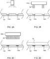
- Figs. 2A to 2D show a schematic representation of a method for printing an image according to an embodiment of the invention comprising the steps of scanning the surface of a recording medium to determine an area of mechanical imprint on the recording medium, applying a first amount of a first coating onto the area of mechanical imprint, and applying an ink onto the recording medium.
- Fig. 2A shows a side view of a recording medium 102, comprising two areas of mechanical imprints 102a and 102b, and an optical sensor 111.
- the optical sensor 111 creates an optical scan of the surface of the recording medium 102 to determine the areas of mechanical imprints 102a and 102b.
- Mechanical imprints 102a and 102b may be the result of mechanical load from transporting wheels.
- Optical sensor 111 may illuminate and/or optically scan the surface of the recording medium 102 thereby optically scanning a height profile and/or surface roughness of the recording medium 102 and determining the areas of mechanical imprints 102a and 102b.
- the areas of mechanical imprints 102a and 102b may be pre-determined (not shown) by establishing the areas of the surface of the recording medium prone to mechanical imprints such as determining the location of one or more transporting wheels relative to the recording medium during transport of the recording medium thereby pre-determining one or more areas where wheel imprints may occur.
- Fig. 2B shows the recording medium 102, comprising two areas of mechanical imprints 102a and 102b, and a print head 104a ejecting droplets 30 of a first coating onto the areas of mechanical imprints 102a and 102b determined as shown in Fig. 2A .
- the print head 104a applies a first amount of a first coating onto the areas of mechanical imprints 102a and 102b by ejecting droplets 30 of a first coating onto the recording medium 102, in particular onto the areas of mechanical imprints 102a and 102b, thereby partially or fully filling these areas.
- Fig. 2C shows the recording medium 102, comprising two areas of mechanical imprints 102a and 102b, and a print head 104b ejecting droplets 40 of an ink onto the recording medium 102 wherein the two areas of mechanical imprints 102a and 102b are filled with a first amount of a first coating as shown in Fig. 2B .
- the print head 104b applies an ink onto the recording medium 102 by ejecting droplets 40 of an ink onto the recording medium 102.
- Fig. 2D shows the recording medium 102, comprising two areas of mechanical imprints 102a and 102b filled with a first coating, and an ink layer 50 applied onto the recording medium 102 as shown in Fig. 2C .
- the ink layer 50 has been applied onto the recording medium 102 and is evenly distributed over the recording medium 102 and as a result from filling the areas of mechanical imprints 102a and 102b in an earlier step as described above the surface of ink layer 50 is also even.
- the glossiness of the ink layer 50 may also be even, whereas if the ink layer 50 would follow the unevenness of the recording medium 102 if the areas of mechanical imprints 102a and 102b would have been left unfilled the resulting surface of ink layer 50 may have been uneven thus resulting in an uneven glossiness of the ink layer 50.
Landscapes
- Ink Jet (AREA)
Abstract
The present invention relates to a method for printing an image onto a recording medium (102) wherein mechanic imprints (102a, 102b) on the recording medium (102) are alleviated by printing a coating in the areas where mechanical imprints occur.
Description
- The present invention relates to a method for printing an image onto a recording medium wherein mechanic imprints on the recording medium are alleviated. Further, the invention relates to a printer for printing an image onto a recording medium configured for performing such a method.
- In a copier, a printer or any other machine in which an image is created using an ink a recording medium may be transported through the printer passing, amongst others, one or more printheads for jetting an ink onto the recording medium. During handling, the recording medium may endure mechanical imprints. For instance, the recording medium may be transported through the printer using transporting wheels which may leave wheel imprints on the recording medium. Other sources of mechanical imprint may be clamps retaining the recording medium in an input or output module of the recording medium or gripping elements for loading the recording medium into the printer.
- These mechanical imprints may reduce the visual quality of the image created by the printer. The mechanical imprint, as such, may be visible in the image. For instance, a groove may be visible where the transporting wheels left a wheel imprint. The mechanical imprint may be invisible directly but visible indirectly. For instance, the groove made due to wheel imprint may be shallow enough to be invisible to the naked eye but may be sufficient to result in a different glossiness of the ink printed at the groove compared to the ink printed in an area other than the groove.
- It is therefore an object of the present invention to overcome the disadvantage of reduced image quality due to mechanical imprints by providing a method for printing an image onto a recording medium wherein mechanical imprints that may be present on the recording medium are alleviated.
- The object of the invention is achieved in a method for printing an image onto a recording medium wherein the method comprises the steps of:
- determining an area of mechanical imprint on the recording medium,
- selectively applying a first amount of a first coating onto the area of mechanical imprint,
- applying an ink onto the recording medium thereby creating an image onto the recording medium.
- In an embodiment, the method for printing an image onto a recording medium further comprises the step of selectively applying a second amount of a first coating onto the recording medium. A second amount of a first coating may be applied on top of the first amount of the first coating and the rest of the recording medium, i.e. the entire recording medium, to create an even surface with the same surface properties over the entire recording medium. The second amount of a first coating may also be applied image wise to cover all areas where ink will be jetted to form an image and thus creating an even surface with the same surface properties where the ink will be jetted. The second amount of a first coating may also be applied in a specific pattern in accordance with a desired glossiness pattern across the image. In other words, where the first amount of the first coating evens the surface roughness of the recording medium thereby alleviating the disadvantages of the mechanical imprints on the recording medium, creating a recording medium surface equal to that of before the mechanical imprints, the second amount of the first coating may introduce desired changes to the printed image such as specific glossiness to certain image elements.
- In an embodiment, the area of mechanical imprint is determined by scanning the recording medium. The one or more areas of mechanical imprints may be scanned using an optical sensor. For instance, a CCD or CMOS image sensor may be used in combination with a laser source to create a three-dimensional height map of the surface of the recording medium. A first amount of a first coating may be applied onto the areas of mechanical imprint determined by scanning the recording medium.
- In an embodiment, the area of mechanical imprinting is determined by pre-determining an area wherein mechanical load may be induced onto the recording medium. During handling and/or transporting the recording medium, the recording medium may endure a mechanical load by for instance transporting wheels, clamps and grips with a specific, known, pressure leaving a pre-determined area and known depth of mechanical imprint on the recording medium. A first amount of a first coating may be applied onto pre-determined areas where the recording medium is prone to mechanical load leading to known mechanical imprints.
- In an aspect of the invention, a printer for printing an image onto a recording medium is provided wherein the printer comprises:
- a printhead for jetting a first amount of a first coating onto a recording medium,
- a printhead for jetting an ink composition onto a recording medium,
- a control unit configured to perform the method according to any of the preceding claims,
-
- Fig. 1A
- shows a schematic representation of an inkjet printing system
- Fig. 1B
- shows a schematic representation of an inkjet print head
- Fig. 2A-2D
- show a schematic representation of a method according to a first exemplary embodiment of the invention
-
Fig. 1A shows an inkjet printing assembly 3. The inkjet printing assembly 3 comprises supporting means for supporting animage receiving medium 2. The supporting means are shown inFig. 1A as aflat surface 1, but alternatively, the supporting means may be a platen, for example a rotatable drum that is rotatable around an axis. The supporting means may be optionally provided with suction holes for holding the image receiving medium in a fixed position with respect to the supporting means. The inkjet printing assembly 3 comprisesprint heads 4a - 4e, mounted on ascanning print carriage 5. Thescanning print carriage 5 is guided by suitable guiding means 6 to move in reciprocation in the main scanning direction X. Eachprint head 4a - 4e comprises anorifice surface 9, which orificesurface 9 is provided with at least oneorifice 8, as is shown inFig. 1B . The print heads 4a - 4e are configured to eject droplets of marking material and/or coating material onto theimage receiving medium 2. - The
image receiving medium 2 may be a medium in web or in sheet form and may be composed of e.g. paper, cardboard, label stock, coated paper, plastic or textile. Alternatively, theimage receiving medium 2 may also be an intermediate member, endless or not. Examples of endless members, which may be moved cyclically, are a belt or a drum. Theimage receiving medium 2 is moved in the sub-scanning direction Y over theflat surface 1 along fiveprint heads 4a - 4e provided with a fluid marking material and/or coating material. - A
scanning print carriage 5 carries the fiveprint heads 4a - 4e and may be moved in reciprocation in the main scanning direction X parallel to theplaten 1, such as to enable scanning of the image receiving medium 2 in the main scanning direction X. Only fiveprint heads 4a - 4e are depicted for demonstrating the invention. In practice an arbitrary number of print heads may be employed. In any case, at least oneprint head 4a - 4e per color of marking material and/or coating material is placed on thescanning print carriage 5. For example, for a black-and-white printer, at least oneprint head 4a - 4e, usually containing black marking material is present. Alternatively, a black-and-white printer may comprise a white marking material, which is to be applied on a black image-receivingmedium 2. For a full-color printer, containing multiple colors, at least oneprint head 4a - 4e for each of the colors, usually black, cyan, magenta and yellow, and for the coating material is present. Often, in a full-color printer, black marking material is used more frequently in comparison to differently colored marking material. Therefore,more print heads 4a - 4e containing black marking material may be provided on thescanning print carriage 5 compared toprint heads 4a - 4e containing marking material in any of the other colors. Alternatively, theprint head 4a - 4e containing black marking material may be larger than any of the print heads 4a - 4e, containing a differently colored marking material. - The
carriage 5 is guided by guidingmeans 6. These guiding means 6 may be a rod as depicted inFig. 1A . Although only onerod 6 is depicted inFig. 1A , a plurality of rods may be used to guide thecarriage 5 carrying the print heads 4. The rod may be driven by suitable driving means (not shown). Alternatively, thecarriage 5 may be guided by other guiding means, such as an arm being able to move thecarriage 5. Another alternative is to move theimage receiving material 2 in the main scanning direction X. - Each
print head 4a - 4e comprises anorifice surface 9 having at least oneorifice 8, in fluid communication with a pressure chamber containing fluid marking material provided in theprint head 4a - 4e. On theorifice surface 9, a number oforifices 8 are arranged in a single linear array parallel to the sub-scanning direction Y, as is shown inFig. 1B . Alternatively, the nozzles may be arranged in the main scanning direction X. Eightorifices 8 perprint head 4a - 4e are depicted inFig. 1B , however obviously in a practical embodiment several hundreds oforifices 8 may be provided perprint head 4a - 4e, optionally arranged in multiple arrays. - As depicted in
Fig. 1A , therespective print heads 4a - 4e are placed parallel to each other. The print heads 4a - 4e may be placed such thatcorresponding orifices 8 of therespective print heads 4a - 4e are positioned in-line in the main scanning direction X. This means that a line of image dots in the main scanning direction X may be formed by selectively activating up to fourorifices 8, each of them being part of adifferent print head 4a - 4e. This parallel positioning of the print heads 4a - 4e with corresponding in-line placement of theorifices 8 is advantageous to increase productivity and/or improve print quality. Alternativelymultiple print heads 4a - 4e may be placed on the print carriage adjacent to each other such that theorifices 8 of therespective print heads 4a - 4e are positioned in a staggered configuration instead of in-line. For instance, this may be done to increase the print resolution or to enlarge the effective print area, which may be addressed in a single scan in the main scanning direction X. The image dots are formed by ejecting droplets of marking material from theorifices 8. - The ink
jet printing assembly 3 may further comprise anoptical sensor 11. As shown inFig. 1A , ascanning print carriage 12 carries theoptical sensor 11 and may be moved in reciprocation in the main scanning direction X parallel to theplaten 1, such as to enable scanning of the image receiving medium 2 in the main scanning direction X. Alternatively, it is possible to apply page-wideoptical sensor 11. If a page-wideoptical sensor 11 is provided, then it may not be necessary to move theoptical sensor 11 means in reciprocation in the main scanning direction X. Theoptical sensor 11 may be a CCD or CMOS image sensor. Theoptical sensor 11 may also comprise a light source to illuminate the surface of the image receiving medium 2 to enable the CCD or CMOS image sensor to receive a clearer image. The light source may be an LED light source or a laser light source. - The
carriage 12 is guided by guidingmeans 7. These guiding means 7 may be a rod as depicted inFig. 1A . Although only onerod 7 is depicted inFig. 1A , a plurality of rods may be used to guide thecarriage 12 carrying theoptical sensor 11. Therod 7 may be driven by suitable driving means (not shown). Alternatively, thecarriage 12 may be guided by other guiding means, such as an arm being able to move thecarriage 12. - The
flat surface 1, thecarriage 5, the print heads 4a - 4e, and the optical sensor are controlled by suitable controlling means 10. -
Figs. 2A to 2D show a schematic representation of a method for printing an image according to an embodiment of the invention comprising the steps of scanning the surface of a recording medium to determine an area of mechanical imprint on the recording medium, applying a first amount of a first coating onto the area of mechanical imprint, and applying an ink onto the recording medium. -
Fig. 2A shows a side view of arecording medium 102, comprising two areas ofmechanical imprints optical sensor 111. Theoptical sensor 111 creates an optical scan of the surface of therecording medium 102 to determine the areas ofmechanical imprints Mechanical imprints Optical sensor 111 may illuminate and/or optically scan the surface of therecording medium 102 thereby optically scanning a height profile and/or surface roughness of therecording medium 102 and determining the areas ofmechanical imprints mechanical imprints
Fig. 2B shows therecording medium 102, comprising two areas ofmechanical imprints print head 104a ejectingdroplets 30 of a first coating onto the areas ofmechanical imprints Fig. 2A . Theprint head 104a applies a first amount of a first coating onto the areas ofmechanical imprints droplets 30 of a first coating onto therecording medium 102, in particular onto the areas ofmechanical imprints
Fig. 2C shows therecording medium 102, comprising two areas ofmechanical imprints print head 104b ejecting droplets 40 of an ink onto therecording medium 102 wherein the two areas ofmechanical imprints Fig. 2B . Theprint head 104b applies an ink onto therecording medium 102 by ejectingdroplets 40 of an ink onto therecording medium 102. -
Fig. 2D shows therecording medium 102, comprising two areas ofmechanical imprints ink layer 50 applied onto therecording medium 102 as shown inFig. 2C . Theink layer 50 has been applied onto therecording medium 102 and is evenly distributed over therecording medium 102 and as a result from filling the areas ofmechanical imprints ink layer 50 is also even. As the surface of theink layer 50 is even the glossiness of theink layer 50 may also be even, whereas if theink layer 50 would follow the unevenness of therecording medium 102 if the areas ofmechanical imprints ink layer 50 may have been uneven thus resulting in an uneven glossiness of theink layer 50. - Detailed embodiments of the present invention are disclosed herein; however, it is to be understood that the disclosed embodiments are merely exemplary of the invention, which can be embodied in various forms. Therefore, specific structural and functional details disclosed herein are not to be interpreted as limiting, but merely as a basis for the claims and as a representative basis for teaching one skilled in the art to variously employ the present invention in virtually any appropriately detailed structure. In particular, features presented and described in separate dependent claims may be applied in combination and any advantageous combination of such claims is herewith disclosed.
- Further, the terms and phrases used herein are not intended to be limiting; but rather, to provide an understandable description of the invention. The terms "a" or "an", as used herein, are defined as one or more than one.
- The invention being thus described, it will be obvious that the same may be varied in many ways. Such variations are not to be regarded as a departure from the spirit and scope of the invention, and all such modifications as would be obvious to one skilled in the art are intended to be included within the scope of the following claims.
Claims (5)
- A method for printing an image onto a recording medium wherein the method comprises the steps of:- determining an area of mechanical imprint on the recording medium;- selectively applying a first amount of a first coating onto the area of mechanical imprint;- applying an ink onto the recording medium thereby creating an image onto the recording medium.
- A method for printing an image onto a recording medium according to claim 1, wherein the method further comprises the step of selectively applying a second amount of a first coating onto the recording medium.
- A method for printing an image onto a recording medium according to claims 1 to 2, wherein the area of mechanical imprint is determined by scanning the recording medium.
- A method for printing an image onto a recording medium according to claims 1 to 2, wherein the area of mechanical imprinting is determined by pre-determining an area wherein mechanical load may be induced onto the recording medium.
- A printer for printing an image onto a recording medium, wherein the printer comprises:- a printhead for jetting a first amount of a first coating onto a recording medium;- a printhead for jetting an ink composition onto a recording medium;- a control unit configured to perform the method according to any of the preceding claims;wherein the printhead for jetting a first amount of a first coating onto a recording medium is further configured to jet a second amount of a first coating onto the recording medium.
Priority Applications (1)
| Application Number | Priority Date | Filing Date | Title |
|---|---|---|---|
| EP18211731.7A EP3666532A1 (en) | 2018-12-11 | 2018-12-11 | A method for alleviating mechanical imprints on a recording medium |
Applications Claiming Priority (1)
| Application Number | Priority Date | Filing Date | Title |
|---|---|---|---|
| EP18211731.7A EP3666532A1 (en) | 2018-12-11 | 2018-12-11 | A method for alleviating mechanical imprints on a recording medium |
Publications (1)
| Publication Number | Publication Date |
|---|---|
| EP3666532A1 true EP3666532A1 (en) | 2020-06-17 |
Family
ID=64664920
Family Applications (1)
| Application Number | Title | Priority Date | Filing Date |
|---|---|---|---|
| EP18211731.7A Withdrawn EP3666532A1 (en) | 2018-12-11 | 2018-12-11 | A method for alleviating mechanical imprints on a recording medium |
Country Status (1)
| Country | Link |
|---|---|
| EP (1) | EP3666532A1 (en) |
Cited By (1)
| Publication number | Priority date | Publication date | Assignee | Title |
|---|---|---|---|---|
| DE102022101538A1 (en) | 2022-01-24 | 2023-07-27 | Homag Gmbh | Method of applying surface manipulating fluids to a surface of a workpiece and applicator |
Citations (3)
| Publication number | Priority date | Publication date | Assignee | Title |
|---|---|---|---|---|
| EP2208542A1 (en) * | 2009-01-16 | 2010-07-21 | Jörg R. Bauer | Method for coating a surface and digital coating system |
| WO2017074686A1 (en) * | 2015-10-29 | 2017-05-04 | Nike Innovate C.V. | Printing layer in response to substrate contour |
| FR3058916A1 (en) * | 2016-11-24 | 2018-05-25 | Reydel Automotive B.V. | METHOD FOR PROCESSING THE SURFACE OF A WORKPIECE, INSTALLATION FOR IMPLEMENTING SAID METHOD AND PIECE OBTAINED BY SAID PROCESSING METHOD |
-
2018
- 2018-12-11 EP EP18211731.7A patent/EP3666532A1/en not_active Withdrawn
Patent Citations (3)
| Publication number | Priority date | Publication date | Assignee | Title |
|---|---|---|---|---|
| EP2208542A1 (en) * | 2009-01-16 | 2010-07-21 | Jörg R. Bauer | Method for coating a surface and digital coating system |
| WO2017074686A1 (en) * | 2015-10-29 | 2017-05-04 | Nike Innovate C.V. | Printing layer in response to substrate contour |
| FR3058916A1 (en) * | 2016-11-24 | 2018-05-25 | Reydel Automotive B.V. | METHOD FOR PROCESSING THE SURFACE OF A WORKPIECE, INSTALLATION FOR IMPLEMENTING SAID METHOD AND PIECE OBTAINED BY SAID PROCESSING METHOD |
Cited By (2)
| Publication number | Priority date | Publication date | Assignee | Title |
|---|---|---|---|---|
| DE102022101538A1 (en) | 2022-01-24 | 2023-07-27 | Homag Gmbh | Method of applying surface manipulating fluids to a surface of a workpiece and applicator |
| WO2023139256A1 (en) * | 2022-01-24 | 2023-07-27 | Homag Gmbh | Method for applying surface-manipulating fluids onto a surface of a workpiece, and application device |
Similar Documents
| Publication | Publication Date | Title |
|---|---|---|
| JP2657560B2 (en) | Dual mode inkjet printer | |
| JP4026652B2 (en) | Inkjet recording apparatus and inkjet recording method | |
| JP5322117B2 (en) | How to print | |
| US6896357B2 (en) | Ink-jet printing head and ink-jet printing apparatus and method | |
| JP5811589B2 (en) | Printing apparatus and printing method | |
| EP3129233B1 (en) | Flatbed printer assembly | |
| US20180304625A1 (en) | Printing apparatus and printing method | |
| JP5790117B2 (en) | Printing apparatus, printing method, and program | |
| WO2013029994A1 (en) | Ink jet printing method and printer | |
| US9120342B2 (en) | Method for full bleed printing | |
| KR100379148B1 (en) | Print image generation method and printing system | |
| US7147301B2 (en) | Ink jet printer that prints using chromatic inks of multiple types | |
| JP6040241B2 (en) | How to print a continuous swath | |
| US20050073542A1 (en) | Inkjet printer | |
| US10272697B2 (en) | Print head carriage assembly | |
| US11186098B2 (en) | Method for locally adjusting gloss while printing an image | |
| US20150231900A1 (en) | Method for forming an inkjet image | |
| US20240100821A1 (en) | Method for controlling a digital inkjet printer | |
| EP3812157B1 (en) | Method for productive printing on a scanning inkjet printer with multi-color print head units | |
| JP2013071410A (en) | Inkjet printer and image recording method | |
| NL2022709B1 (en) | A liquid handling system for a printer | |
| JP2018176610A (en) | Ink jet printer and printing method |
Legal Events
| Date | Code | Title | Description |
|---|---|---|---|
| PUAI | Public reference made under article 153(3) epc to a published international application that has entered the european phase |
Free format text: ORIGINAL CODE: 0009012 |
|
| STAA | Information on the status of an ep patent application or granted ep patent |
Free format text: STATUS: THE APPLICATION HAS BEEN PUBLISHED |
|
| AK | Designated contracting states |
Kind code of ref document: A1 Designated state(s): AL AT BE BG CH CY CZ DE DK EE ES FI FR GB GR HR HU IE IS IT LI LT LU LV MC MK MT NL NO PL PT RO RS SE SI SK SM TR |
|
| AX | Request for extension of the european patent |
Extension state: BA ME |
|
| STAA | Information on the status of an ep patent application or granted ep patent |
Free format text: STATUS: THE APPLICATION HAS BEEN WITHDRAWN |
|
| 18W | Application withdrawn |
Effective date: 20200717 |