EP3666432A1 - Device for securing a boring device to a boring grate comprising an expandable ball hub - Google Patents
Device for securing a boring device to a boring grate comprising an expandable ball hub Download PDFInfo
- Publication number
- EP3666432A1 EP3666432A1 EP19212196.0A EP19212196A EP3666432A1 EP 3666432 A1 EP3666432 A1 EP 3666432A1 EP 19212196 A EP19212196 A EP 19212196A EP 3666432 A1 EP3666432 A1 EP 3666432A1
- Authority
- EP
- European Patent Office
- Prior art keywords
- drilling
- grid
- expansion cone
- ring
- locking
- Prior art date
- Legal status (The legal status is an assumption and is not a legal conclusion. Google has not performed a legal analysis and makes no representation as to the accuracy of the status listed.)
- Granted
Links
- 238000005553 drilling Methods 0.000 claims abstract description 117
- 230000002093 peripheral effect Effects 0.000 claims description 28
- 230000000903 blocking effect Effects 0.000 claims description 19
- 230000000295 complement effect Effects 0.000 claims description 10
- 230000001105 regulatory effect Effects 0.000 claims description 6
- 238000005304 joining Methods 0.000 claims description 3
- 238000005520 cutting process Methods 0.000 description 9
- 239000012530 fluid Substances 0.000 description 7
- 230000000694 effects Effects 0.000 description 6
- 238000006073 displacement reaction Methods 0.000 description 4
- 208000031968 Cadaver Diseases 0.000 description 3
- 235000008612 Gnetum gnemon Nutrition 0.000 description 3
- 240000000018 Gnetum gnemon Species 0.000 description 3
- 238000004519 manufacturing process Methods 0.000 description 2
- 238000000034 method Methods 0.000 description 2
- 238000012550 audit Methods 0.000 description 1
- 238000006243 chemical reaction Methods 0.000 description 1
- 230000006835 compression Effects 0.000 description 1
- 238000007906 compression Methods 0.000 description 1
- 230000001419 dependent effect Effects 0.000 description 1
- 238000005461 lubrication Methods 0.000 description 1
- 238000012423 maintenance Methods 0.000 description 1
- 239000000463 material Substances 0.000 description 1
- 230000013011 mating Effects 0.000 description 1
- 230000001681 protective effect Effects 0.000 description 1
- 238000005096 rolling process Methods 0.000 description 1
- 238000003860 storage Methods 0.000 description 1
- 238000005482 strain hardening Methods 0.000 description 1
- 230000001360 synchronised effect Effects 0.000 description 1
- 230000009466 transformation Effects 0.000 description 1
Images


Classifications
-
- B—PERFORMING OPERATIONS; TRANSPORTING
- B23—MACHINE TOOLS; METAL-WORKING NOT OTHERWISE PROVIDED FOR
- B23B—TURNING; BORING
- B23B49/00—Measuring or gauging equipment on boring machines for positioning or guiding the drill; Devices for indicating failure of drills during boring; Centering devices for holes to be bored
- B23B49/02—Boring templates or bushings
- B23B49/023—Bushings and their connection to the template
-
- B—PERFORMING OPERATIONS; TRANSPORTING
- B23—MACHINE TOOLS; METAL-WORKING NOT OTHERWISE PROVIDED FOR
- B23B—TURNING; BORING
- B23B2215/00—Details of workpieces
- B23B2215/04—Aircraft components
-
- B—PERFORMING OPERATIONS; TRANSPORTING
- B23—MACHINE TOOLS; METAL-WORKING NOT OTHERWISE PROVIDED FOR
- B23B—TURNING; BORING
- B23B41/00—Boring or drilling machines or devices specially adapted for particular work; Accessories specially adapted therefor
-
- B—PERFORMING OPERATIONS; TRANSPORTING
- B23—MACHINE TOOLS; METAL-WORKING NOT OTHERWISE PROVIDED FOR
- B23B—TURNING; BORING
- B23B49/00—Measuring or gauging equipment on boring machines for positioning or guiding the drill; Devices for indicating failure of drills during boring; Centering devices for holes to be bored
- B23B49/02—Boring templates or bushings
Definitions
- the field of the invention is that of the design and manufacture of the fastening devices used to fasten drilling devices to drilling grids.
- the locations of the holes to be made are generally defined by means of drilling grids.
- a drilling grid is in the form of a plate traversed by a plurality of positioning bores.
- Such a grid is intended to be fixedly placed near an element to be drilled, this in a particular predetermined position so that the position of the positioning bores corresponds to locations where holes must be drilled in the element to be drilled. drill.
- a drilling device is fixed to one of the positioning bores and a hole is made in the element to be drilled.
- the drilling device is then secured to another bore of the grid to make another hole in the element to be drilled.
- the drilling device is thus successively secured to different bores for positioning the grid so as to make a plurality of holes in the element to be drilled.
- the drilling devices generally used are automatic advance drilling devices (comprising a single motor for driving a drilling spindle in translation and in rotation along the same axis) or drilling devices with controlled cutting parameters (comprising a feed motor and a rotation motor to drive a drilling spindle in translation and in rotation along the same axis).
- the fastening of a piercing device to the grid is carried out by means of a fastening device comprising an expandable hub.
- the displacement in translation of the expansion cone with respect to the expandable ring is obtained by a jack, generally pneumatic.
- This cylinder is arranged perpendicular to the expansion cone and for driving it via a movement transformation device such as rollers rolling in a slide inclined relative to the axes of the cone and of the cylinder or a spreader.
- the axial force applied to the expansion cone generates a contact pressure between the expandable hub and the positioning bore in which it is housed in the locked position.
- This contact pressure and the associated friction must be sufficient to oppose the reaction torque and the thrust forces along the drilling axis transmitted to the drill during a drilling operation and guarantee that the drilling device is correctly secured to the grid. The reliability of this connection is therefore dependent on the axial force generated by the jack.
- the piercing device can slide relative to the grid during a piercing operation. Such sliding can have repercussions on the quality of the drilling, in particular on its depth if the device drilling moves back with respect to the grid during a drilling operation. This is not acceptable since the geometric tolerances imposed in the aeronautical sector are often low.
- the risk of the drilling device sliding relative to the grid during a drilling operation is all the greater the harder the material to be drilled, the more the cutting tool is worn (in these two cases, the more thrust and the torque transmitted to the drill during drilling) and that the drilling is carried out with lubrication.
- Another solution to avoid the sliding of the piercing device relative to the piercing grid is to implement additional mechanical restraint systems comprising a bayonet system 1 ⁇ 4 turn integral with the piercing device provided to cooperate with shouldered screws integral with the drilling grid.
- Such a system has the disadvantage of being bulky and not being compatible with a tight grid spacing.
- the invention particularly aims to provide an effective solution to at least some of these different problems.
- an objective of the invention is to provide a device for securing a drilling device to a drilling grid which makes it possible to make holes with small geometric tolerances.
- the invention aims, according to at least one embodiment, to provide such a securing device which ensures good repeatability over the depth of a plurality of holes.
- Another objective of the invention is to providing such a securing device which makes it possible to prevent the piercing device from slipping, in particular backward, with respect to the piercing grid during a piercing operation.
- the invention aims, according to at least one embodiment, to provide such a fastening device which is compact.
- Another object of the invention is, according to at least one embodiment, to provide such a fastening device which requires the deployment of relatively reduced forces to ensure that an effective drilling device is maintained in position relative to a drilling grid during a drilling operation.
- Another objective of the invention is, according to at least one embodiment, to provide such a fastening device which is compact and / or simple in design and / or robust.
- the invention consists in implementing an expandable ball hub to ensure the attachment of a drilling device to a drilling grid.
- balls which are housed in a peripheral housing integral with a positioning bore of a drilling grid makes it possible to simply but effectively block in translation the drilling device relative to the grid.
- the drilling device can not move in translation along the drilling axis relative to the drilling grid, in particular it can not move back. This guarantees compliance with the low geometric tolerances which are generally imposed, and in particular the repeatability of the depth of successive drillings.
- the technique according to the invention thus makes it possible, by implementing a compact and simple solution, to produce quality bores.
- said balls are housed in longitudinal grooves formed on the surface of said expansion cone.
- each of said grooves comprises a first stage and a second stage separated by an inclined ramp, the bottom of said first stage being closer to the longitudinal axis of said expansion cone than the bottom, said balls being located against said first stage in said unlocking position and against said second stage in said locking position.
- said grooves are not through.
- said positioning bores are formed in said drilling grid.
- a securing device comprises guide rings intended to be secured to said drilling grid and traversed by said positioning bore.
- peripheral blocking housings are formed in said grid or in said guide rings.
- said body comprises a stop intended to come into abutment against a surface of said drilling grid or against a surface of said guide rings oriented towards said fastening device.
- said guide ring comprises a shoulder of complementary shape of a housing formed in said bores for positioning of said grid.
- said shoulder is preferably formed on the side of said grid opposite to that oriented towards said securing device.
- the passage of said cone from its release position to its locking position takes place in the direction of the surface of said piercing grid oriented towards said securing device, or vice versa.
- said means for driving in translation of said expansion cone comprise a jack, said jack comprising a cylinder arranged inside said body and a piston mounted movable in translation inside said cylinder along the axis. for translating said expansion cone, said expansion cone being integral in translation with said piston.
- said cylinder is double-acting.
- said cylinder of said cylinder comprises a locking chamber placed on one side of the piston and intended to be supplied with power to move said expansion cone in its locked position and a release chamber placed on the other side of the piston and intended to be powered to move said expansion cone in its release position, the surface of the face of the piston located in said unlocking chamber being greater than the surface of the face of said piston located in said locking chamber.
- a device comprises means for regulating said means for driving in translation of said expansion cone, said regulating means being configured so that the speed of movement in translation printed on said expansion cone by said drive means is greater during its passage from said release position to said locking position than during its passage from said locking position to said release position.
- a fastening device according to the invention is traversed right through by a drilling barrel.
- Such a fastening device can be implemented to ensure the fastening of any type of drilling device (or drill) to a drilling grid which ranks including, but not limited to, drills with controlled torque parameters and drills with automatic advance.
- such a fastening device 1 comprises a body 10 comprising at a first end of the first fastening means 11 to a drilling device, and at its opposite end of the second fastening means 12 to a drilling grid 13.
- a drilling grid 13 conventionally comprises a plate 130 traversed by a plurality of positioning bores 131.
- a plate 130 can be flat, curved or have any other shape suitable for drilling the element to be drilled . It has a surface 132 oriented on the side of the piercing device, that is to say on the side of the securing device, and an opposite surface 133 oriented on the side of an element to be drilled.
- the first means 11 for securing the device to a drill include a knurled nut 110 capable of being screwed onto a threaded portion 113 of the body 10 or more precisely of a plug 14 which will be described in more detail below.
- the nut 110 can be tightened by means of a hook wrench which is housed in the holes 111.
- the knurled nut 110 has a shoulder 114.
- the second means 12 for securing the device to a drilling grid comprise an expandable ball hub which will be described in more detail below.
- the body 10 comprises a first portion 100 of large diameter extended by a second portion 101 of smaller diameter.
- the first portion 100 is traversed by a bore 1220.
- This bore 1220 is open to the outside at its anterior end and closed by means of a plug 14 screwed into the body 10.
- the plug 14 carries an O-ring 140 to ensure a hermetic closure of the bore 1220.
- the plug 14 is capable of housing an inner ring 141 which is held there between a shoulder 142 formed inside the plug 14 and a shoulder 114 of the knurled nut 110.
- This inner ring 141 is designed to be secured to the end of the drilling device to be joined to the joining device.
- the second portion 101 is crossed laterally by slots 1010 which allow the evacuation of the chips during a drilling operation.
- the rear end of the second portion 101 has a threaded portion 1011 on which is screwed a nut 15 with transverse holes 150 to allow the introduction of a lug wrench to ensure the tightening of the nut 15 on the body 10.
- the nut 15 comprises a stop 151 defining a bearing surface intended to come into abutment against the surface 132 of the grid 13 oriented towards the securing device when the latter is secured to the grid 13.
- the expandable ring 120 comprises a portion 1200 with an essentially cylindrical outer contour extended at one of its ends by a shoulder 1201 having a flat (not shown).
- This shoulder 1201 is housed inside a bore 1012 formed at the rear end of the second portion 101 of the body and having a flat 1013 of shape complementary to the flat of the expandable ring 120.
- the expandable ring 120 is secured to the body 10 by means of the nut 15 which locks it in translation with respect to the body 10.
- the expandable ring 120 is locked in rotation with respect to the body 10 by the flats.
- Longitudinal slots 1204 are formed longitudinally at the periphery of the portion 1200 of the expandable ring 120 so as to allow the expandable ring to expand and to retract as will emerge more clearly later.
- the expandable ring 120 is crossed by a conical bore 1202 (or more exactly frustoconical) formed along a longitudinal axis of the expandable ring.
- the angle of the bore 1202 is such that the conical bore 1202 has a small diameter end on the side of the body 10 and a larger diameter end opposite.
- the rear end of the expandable ring 120 is crossed by radial orifices 1203 formed along axes perpendicular to the longitudinal axis of the expandable ring 120 and distributed uniformly around this longitudinal axis.
- the conical bore 1202 of the expandable ring 120 houses the expansion cone 121.
- the expansion cone 121 has an outer peripheral contour of shape complementary to the inner peripheral contour of the conical bore 1202.
- the expansion cone 121 is mounted movable in translation inside the conical bore 1202 along the longitudinal axis thereof.
- Longitudinal grooves 1210 are formed on the surface of the expansion cone 121.
- these grooves 1210 are stepped. They each include a first stage 12100 and a second stage 12101 separated by an inclined ramp 12102. The bottom of each stage extends essentially parallel to the longitudinal axis of the expansion cone 121. The bottom of the first stage 12100 is closer from the longitudinal axis of the expansion cone as the bottom of the second stage 12101.
- the grooves 1210 are preferably non-emerging, that is to say that they are not open to the outside at the rear end of the expansion cone 121.
- Each groove 1210 houses a locking ball 123.
- each orifice 1203 is slightly tightened to prevent the ball 123 which is housed therein from coming out completely .
- the outside diameter of each orifice 1203 can for example have a work hardening 1205 forming a projection inside the orifice as shown in FIG. figure 11 .
- Another solution could of course be implemented. This diameter is chosen so that the ball 123 which is housed therein forms a projection on the outer surface of the expandable ring 120.
- the expansion cone 121 is secured to the end of the hollow rod 1223 of a jack making it possible to move the expansion cone 121 in translation inside the conical bore 1202.
- Peripheral slots 1221 pass through the rod 1223 allowing the evacuation of shavings during a drilling operation. These lights 1221 extend opposite the lights 1010 formed in the body 10.
- the longitudinal axis of the cylinder rod 1223 extends co-axially with the drilling barrel.
- the rod 1223 carries transverse pins 1222 which are each housed in a longitudinal groove 1014 formed for this purpose in the body 10.
- the pins 1222 and the grooves 1014 make it possible to block in rotation the rod 1223 relative to the body 10 and to allow the translation of the rod 1223 in the body 10 along its longitudinal axis.
- the rod 1223 carries a piston 1224 housed in the bore 1220. It extends on one side of the piston 1224 in a bore 1015 formed in the body 10 and emerging in the bore 1220. It extends on the other side of the piston 1224 in a bore 143 formed in the plug 14.
- the bores 1015 and 143 each have a peripheral groove 1016, 144 housing an O-ring 1017, 145 making it possible, with the seal 140, to seal the bore 1220 which constitutes the cylinder of a cylinder inside which the piston 1224 is mounted movable in translation.
- the piston 1224 delimits inside the cylinder 1220 a locking chamber 12201 and a release chamber 12202.
- the surface of the face of the piston located in the unlocking chamber is greater than the surface of the face of said piston located in said unlocking chamber locking.
- the body 10 is crossed by a locking channel 1225 and by a release channel 1226 opening respectively into the locking chamber 12201 and into the release chamber 12202 and making it possible to supply them with pressurized fluid.
- the locking channel 1225 and the release channel 1226 are respectively connected to a locking pipe 1227 and a release pipe 1228 intended to be connected to means for supplying pressurized fluid.
- the guide ring 124 is traversed by an internal bore 1240 inside which is formed a peripheral internal blocking housing 1241 which is in the form of a groove. It has a cylindrical outer contour extended by a shoulder 1242.
- each positioning bore 131 comprises two internal portions bored 1310, 1311 of different diameters to the interface from which a shoulder 1312 is formed.
- the shoulder 1312 is formed on the side of the piercing grid 13 located opposite the side against which the stop 151 is intended to come to bear.
- the guide ring 124 thus has an external shape complementary to the internal shape of the positioning bore 131.
- the expandable ring 120 is intended to be housed in a positioning bore (the positioning bore 131 of the grid or the internal bore 1240 of the ring guide 124) integral with the drilling grid 13.
- a positioning bore the positioning bore 131 of the grid or the internal bore 1240 of the ring guide 1204.
- the jack makes it possible to move the piston 1224 and the cone 121 integral with its rod 1223 from one to the other of its positions.
- the balls 123 are located against the first stage 12100 of the corresponding groove 1210 in the unlocked position and against the second stage 12101 in the blocked position.
- the securing device comprises means for regulating the drive means in translation of the expansion cone, that is to say of the jack.
- These regulation means are configured so that the translational movement speed imparted to the expansion cone by the jack is lower during its passage from the release position to the blocking position than that during its passage from the blocking position to the release position.
- the fastening device is traversed right through by a piercing barrel 16 which allows the rotation and translation movement of a spindle and the cutting tool secured at its end during a drilling operation.
- a chipbreaker 17 is placed at the rear end of the drilling barrel 16.
- a securing device 1 according to the invention is firstly secured at the end of a piercing device.
- a knurled nut 110 is threaded at the end of the housing of the piercing device and then a ring 141 is secured to the end of the housing of the piercing device so as to be stationary relative thereto. It can for example be force-fitted and / or glued to the end of the piercing device.
- the knurled nut 110 is held integral with the drilling device by the ring 141.
- This nut is movable in rotation relative to the casing of the drilling device, as well as in translation until it comes to bear against the ring 141.
- the body 10 of the securing device is brought closer to the end of the piercing device so as to introduce the ring 141 until it comes into abutment against the shoulder 142 of the plug 14. Then the knurled nut 110 is screwed onto the threaded portion 113 of complementary shape provided for this purpose on the plug 14 of the securing device until the ring 141 is compressed between the shoulder 142 of the plug 14 and the shoulder 114 of the knurled nut 110. The securing device is then fixed to the piercing device so that they are immobilized relative to each other.
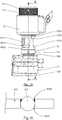
- the figure 12 illustrates a securing device 1 fixed to the end of a drilling tool 2 shown partially and schematically.
- the spindle of the piercing device as well as possibly the cutting tool which could already be secured to it, then extends (s) in the longitudinal axis of the fastening device, if necessary in part to the inside the drill barrel 16.
- the locking 1227 and release 1228 pipes are then connected to the pressurized fluid supply network, in particular compressed air, of the drilling device.
- the jack is then controlled so as to place the expansion cone 121 in its release position, the locking balls 123 in their unlocking position and the expanding ring 120 in its released state if they were not in this position. / state (cf. figures 5 and 6 ).
- the pressurized fluid is introduced into the release chamber 12202 via the release line 1228.
- the piston 1224 translates inside the cylinder 1220 along the longitudinal axis of the piston in the direction of the end of the attachment device 1 intended to be attached to a drilling grid (see arrow D).
- the piston rod 1223 follows the translational movement of the piston 1224 so that the expansion cone 121 is translated relative to the expandable ring 120 to be placed in its release position in which its large diameter end is distant from the end of large diameter of the conical bore 1202 of the expandable ring 120.
- the expansion cone 121 does not act on the expandable ring 120.
- the expandable ring 120 is then in its relaxed state in which its outer diameter is smaller than the internal diameter of the positioning bores 131 of the drilling grille 13, or of the internal bores 1240 of the guide rings 124 when they are used.
- the locking balls 123 roll on the surface of the expansion cone 121 in their respective grooves 1210 first against the second stage 12101, then against the inclined ramp 12102, to come into contact with the first floor 12100.
- the locking balls 123 move freely in translation inside the radial orifices 1203, along their longitudinal axis, until they are placed in their unlocked position in which they do not protrude at the surface of the expandable ring 120.
- the guide rings 124 are optionally forced into the positioning bores 131 of the drilling grid 13, from the face 133 of the grid oriented towards the side of the element to be drilled, until their shoulder 1242 comes to bear against the shoulder 1312 of the corresponding positioning bore 131.
- each positioning ring 124 oriented towards the side of the surface 132 of the grid against which the stop 151 is intended to come into abutment then forms slightly protruding from this surface by a few tenths of a millimeter.
- the piercing device and the fastening device which is attached to it are then moved so as to introduce the expanding ring 120 into the internal bore 1240 of the guide ring 124 of the piercing grid corresponding to the location at which it is desired. drilling, until the stop 151 is in abutment against the guide ring 124 if such rings are used or against the surface 132 of the drilling grid 13 oriented towards the side of the tool drilling, that is to say on the side opposite the side of the grid facing the element to be drilled.
- This movement can be carried out manually by an operator or by means of a manipulator arm (robot arm) if the piercing device is secured to the end of such an arm.
- Pressurized fluid is then admitted via the locking pipe 1127 into the locking chamber 12201 to place the expansion cone 121 in its locked position, the expandable ring in its expanded state and the locking balls 123 in their position blocking (cf. figures 8 and 9 ).
- the piston 1224 translates inside the cylinder 1220 along the longitudinal axis of the piston in the direction of the end of the attachment device intended to be attached to a device drilling (see arrow V).
- the piston rod 1223 follows the translational movement of the piston 1224 so that the expansion cone 121 translates relative to the expandable ring 120 to place itself in its locking position in which its large diameter end is brought closer to the end of large diameter of the conical bore 1202 of the expandable ring 120.
- the expansion cone 121 thus acts on the expandable ring 120.
- the expandable ring 120 is then in its expanded state in which its outside diameter is increased until the expanding ring 120 compresses against the internal bore 1240 of the corresponding guide ring 124 or against the internal wall of the grid positioning bore if no guide ring is fitted implemented.
- the securing device is thus held integral with the drilling grid under the effect of friction between the expandable ring and the guide ring or, where appropriate, the positioning bore.
- the locking balls 123 roll on the surface of the expansion cone 121 in their respective grooves 1210 first against the first stage 12100, then against the inclined ramp 12102, to come into contact with the second floor 12101.
- the locking balls 123 move in translation inside the radial orifices 1203, along their longitudinal axis, until they are placed in their blocking position in which they protrude from the surface of the expandable ring 120 so that they are introduced into the inner peripheral blocking housing 1241 of the corresponding guide ring 124 or directly formed in the corresponding positioning bore if no guide ring is used.
- the locking balls 123 associated with the inner peripheral blocking housing 1241 make it possible to ensure a translation locking of the fastening device relative to the drilling grid, and thus to avoid any displacement in translation of the drilling device relative to the grid along the drilling axis during a drilling operation.
- the introduction of the locking balls 123 into the inner peripheral blocking housing 1241 of the guide ring 124 tends to induce a compressive force of the shoulder 1242 of the guide ring 124 against the shoulder 1312 of the drilling grid, as well as a compression force of the end of the guide ring 124 against the stop 151.
- Such an attachment does not require feeding the cylinder with a very high pressure. A pressure of around 6 bars is sufficient.
- a drilling operation can then be launched.
- the spindle and the cutting tool placed at its end move in translation and in rotation along the same axis inside the drilling barrel 16.
- a chipbreaker 17, optionally placed at the end of the drilling barrel 16 makes it possible to break the chip formed during drilling and to guide it inside the drilling barrel in the direction of the slots 1221 and 1010 formed respectively in the rod 1223 and into the body 10 in order to be evacuated.
- a suction nozzle 18 may have been previously secured to the body 10 opposite the lights 1221 and 1010 to suck the chips and evacuate them to a storage and / or treatment area.
- a protective ring 19, crossed by peripheral ports 190, may optionally have been able to be interposed between the body 10 and the suction nozzle 18, to prevent an operator from being able to introduce the fingers into the ports 1221 and 1010.
- the unlocking chamber 12202 is again pressurized with compressed fluid to generate the unlocking of the device according to the procedure described above.
- the admission of the compressed fluid into the cylinder is regulated in such a way that the speed of the piston to move towards its locking position is higher than that to move to its release position. This makes it possible to guarantee that the cutting tool has come out of the piercing grid before the detaching device can be detached from the piercing grid. This avoids breaking the cutting tool when the drilling device is detached.
- the pipes 1227, 1228 are preferably connected downstream of the actuating trigger or of the actuating valve making it possible to supply the motor of the drilling device when a drilling operation is activated.
- the start of a drilling operation is synchronized with the locking of the fastening device so as to guarantee that the drilling operation begins after the fastening of the drilling device, and vice versa.
- an expandable collar ring could be implemented.
- This flange could be housed in a housing of complementary shape formed directly in a positioning bore or in a guide ring like the locking balls. Alternatively, this flange could bear against the surface of the grid placed on the side of the element to be drilled.
- the locking balls and the flange constitute means for blocking in translation the fastening device relative to the grid along the drilling axis.
- the direction of movement of the expansion cone to move from its release position to its locking position may be reversed. In this case, it will pass from its release position to its locking position by being translated towards the surface of the drilling grid oriented towards the element to be drilled.
- the balls may first of all come into contact with the edge of the peripheral blocking housing oriented towards the piercing device.
- the balls will thus be housed in the peripheral blocking housing by generating an axial force which tends to compress the stop against the grid or the guide ring.
- the balls can be directly housed in peripheral blocking housing without generating axial force.
Abstract
La présente invention concerne un dispositif de solidarisation (1) d'un dispositif de perçage (2) à une grille de perçage (13) munie d'une pluralité d'alésages de positionnement (131), ledit dispositif de solidarisation comprenant des moyens de solidarisation à la grille (13), ces moyens de solidarisation comprenant un moyeu expansible à billes (123).The present invention relates to a device for securing (1) a drilling device (2) to a drilling grid (13) provided with a plurality of positioning bores (131), said fixing device comprising means for securing to the grid (13), these securing means comprising an expandable ball hub (123).
Description
Le domaine de l'invention est celui de la conception et de la fabrication des dispositifs de solidarisation mis en œuvre pour solidariser des dispositifs de perçage à des grilles de perçage.The field of the invention is that of the design and manufacture of the fastening devices used to fasten drilling devices to drilling grids.
Dans le domaine de l'aéronautique, des perçages sont couramment réalisés dans les structures avionnées au cours de la fabrication des avions.In the field of aeronautics, drilling is commonly carried out in aircraft structures during the manufacture of aircraft.
Les emplacements des perçages à réaliser sont généralement définis au moyen de grilles de perçage.The locations of the holes to be made are generally defined by means of drilling grids.
Une grille de perçage se présente sous la forme d'une plaque traversée par une pluralité d'alésages de positionnement.A drilling grid is in the form of a plate traversed by a plurality of positioning bores.
Une telle grille est destinée à être placée de manière fixe à proximité d'un élément à percer, ceci dans une position particulière prédéterminée de sorte que la position des alésages de positionnement corresponde à des emplacements où des perçages doivent être pratiqués dans l'élément à percer.Such a grid is intended to be fixedly placed near an element to be drilled, this in a particular predetermined position so that the position of the positioning bores corresponds to locations where holes must be drilled in the element to be drilled. drill.
Une fois la grille de perçage ainsi mise en place, on vient fixer un dispositif de perçage à l'un des alésages de positionnement puis on y pratique un trou dans l'élément à percer. Le dispositif de perçage est ensuite solidarisé à un autre alésage de la grille pour pratiquer un autre trou dans l'élément à percer. Le dispositif de perçage est ainsi successivement solidarisé à différents alésages de positionnement de la grille de sorte à pratiquer une pluralité de perçages dans l'élément à percer.Once the drilling grid has been put in place, a drilling device is fixed to one of the positioning bores and a hole is made in the element to be drilled. The drilling device is then secured to another bore of the grid to make another hole in the element to be drilled. The drilling device is thus successively secured to different bores for positioning the grid so as to make a plurality of holes in the element to be drilled.
Les dispositifs de perçage généralement mis en œuvre sont des dispositifs de perçage à avance automatique (comprenant un unique moteur pour entrainer une broche de perçage en translation et en rotation selon un même axe) ou des dispositifs de perçage à paramètres de coupe contrôlés (comprenant un moteur d'avance et un moteur de rotation pour entrainer une broche de perçage en translation et en rotation selon un même axe).The drilling devices generally used are automatic advance drilling devices (comprising a single motor for driving a drilling spindle in translation and in rotation along the same axis) or drilling devices with controlled cutting parameters (comprising a feed motor and a rotation motor to drive a drilling spindle in translation and in rotation along the same axis).
La solidarisation d'un dispositif de perçage à la grille est réalisée au moyen d'un dispositif de solidarisation comprenant un moyeu expansible.The fastening of a piercing device to the grid is carried out by means of a fastening device comprising an expandable hub.
Un tel moyeu expansible comprend :
- une bague expansible cylindrique traversée par un alésage intérieur conique ménagé le long d'un axe longitudinal de la bague expansible ;
- un cône d'expansion logé à l'intérieur de l'alésage conique de la bague expansible et dont le contour périphérique extérieur est complémentaire de l'alésage conique,
- des moyens d'entrainement en translation du cône d'expansion à l'intérieur de l'alésage conique selon l'axe longitudinal entre au moins :
- une position de libération dans laquelle le cône est déplacé du côté de plus fort diamètre de l'alésage conique de la bague expansible si bien que celle-ci se trouve dans un état relâché dans lequel son diamètre extérieur est inférieur à celui des alésages de positionnement de la grille de sorte qu'elle puisse y être introduite ou en être extraite ;
- une position de verrouillage dans laquelle le cône est déplacé du côté de plus faible diamètre de l'alésage conique de la bague expansible si bien que celle-ci se trouve dans un état expansé dans lequel son diamètre extérieur est augmenté de sorte à maintenir le dispositif de perçage solidaire de la grille de perçage par friction de la bague expansible contre les parois internes de l'alésage de positionnement dans lequel elle se trouve.
- a cylindrical expanding ring crossed by a conical inner bore formed along a longitudinal axis of the expandable ring;
- an expansion cone housed inside the conical bore of the expandable ring and whose external peripheral contour is complementary to the conical bore,
- means for driving in translation the expansion cone inside the conical bore along the longitudinal axis between at least:
- a release position in which the cone is moved to the side of the larger diameter of the conical bore of the expandable ring so that the latter is in a relaxed state in which its outside diameter is less than that of the positioning bores the grid so that it can be inserted into or removed from it;
- a locking position in which the cone is moved to the smaller diameter side of the conical bore of the expandable ring so that the latter is in an expanded state in which its outer diameter is increased so as to maintain the device drilling integral with the drilling grid by friction of the expandable ring against the internal walls of the positioning bore in which it is located.
Le déplacement en translation du cône d'expansion vis-à-vis de la bague expansible est obtenu par un vérin, en général pneumatique. Ce vérin est disposé de façon perpendiculaire au cône d'expansion et pour l'entrainer par l'intermédiaire d'un dispositif de transformation de mouvement tel que des galets roulant dans une glissière inclinée par rapport aux axes du cône et du vérin ou encore un palonnier.The displacement in translation of the expansion cone with respect to the expandable ring is obtained by a jack, generally pneumatic. This cylinder is arranged perpendicular to the expansion cone and for driving it via a movement transformation device such as rollers rolling in a slide inclined relative to the axes of the cone and of the cylinder or a spreader.
L'effort axial appliqué sur le cône d'expansion engendre une pression de contact entre le moyeu expansible et l'alésage de positionnement dans lequel il est logé en position de verrouillage. Cette pression de contact et les frottements associés doivent être suffisants pour s'opposer au couple de réaction et aux efforts de poussée selon l'axe de perçage transmis à la perceuse au cours d'une opération de perçage et garantir que le dispositif de perçage est correctement solidarisé à la grille. La fiabilité de cette solidarisation est donc dépendante de la force axiale générée par le vérin.The axial force applied to the expansion cone generates a contact pressure between the expandable hub and the positioning bore in which it is housed in the locked position. This contact pressure and the associated friction must be sufficient to oppose the reaction torque and the thrust forces along the drilling axis transmitted to the drill during a drilling operation and guarantee that the drilling device is correctly secured to the grid. The reliability of this connection is therefore dependent on the axial force generated by the jack.
Dans le cas d'une solidarisation insuffisante, le dispositif de perçage peut glisser par rapport à la grille au cours d'une opération de perçage. Un tel glissement peut avoir des répercutions sur la qualité du perçage, en particulier sur sa profondeur si le dispositif de perçage recule par rapport à la grille au cours d'une opération de perçage. Ceci n'est pas acceptable dans la mesure où les tolérances géométriques imposées dans le secteur aéronautique sont souvent faibles.In the event of insufficient joining, the piercing device can slide relative to the grid during a piercing operation. Such sliding can have repercussions on the quality of the drilling, in particular on its depth if the device drilling moves back with respect to the grid during a drilling operation. This is not acceptable since the geometric tolerances imposed in the aeronautical sector are often low.
Le risque de voir le dispositif de perçage glisser par rapport à la grille au cours d'une opération de perçage est d'autant plus grand que le matériau à percer est dur, que l'outil coupant est usé (dans ces deux cas, la poussée et le couple transmis à la perceuse en cours de perçage sont plus importants) et que le perçage est réalisé avec lubrification.The risk of the drilling device sliding relative to the grid during a drilling operation is all the greater the harder the material to be drilled, the more the cutting tool is worn (in these two cases, the more thrust and the torque transmitted to the drill during drilling) and that the drilling is carried out with lubrication.
Pour éviter qu'un tel déplacement du dispositif de perçage se produise, il est connu d'augmenter la taille du vérin ou d'utiliser une pression plus importante ce qui peut avoir des inconvénients en terme d'encombrement ou fatigue mécanique des composants.To prevent such displacement of the piercing device from occurring, it is known to increase the size of the jack or to use a higher pressure which can have drawbacks in terms of space or mechanical fatigue of the components.
Une autre solution pour éviter le glissement du dispositif de perçage par rapport à la grille de perçage est de mettre en œuvre des systèmes de retenue complémentaire mécanique comprenant un système à baïonnette ¼ de tour solidaire du dispositif de perçage prévue pour venir coopérer avec des vis épaulées solidaires de la grille de perçage.Another solution to avoid the sliding of the piercing device relative to the piercing grid is to implement additional mechanical restraint systems comprising a bayonet system ¼ turn integral with the piercing device provided to cooperate with shouldered screws integral with the drilling grid.
Un tel système présente l'inconvénient d'être encombrant et ne pas être compatible avec un entraxe de grille serré.Such a system has the disadvantage of being bulky and not being compatible with a tight grid spacing.
Les dispositifs de solidarisation des dispositifs de perçage aux grilles de perçages peuvent donc encore être améliorés notamment pour :
- limiter le risque de voir le dispositif de perçage glisser par rapport à la grille de perçage au cours d'une opération de perçage, ainsi que les inconvénients inhérents à un tel glissement ;
- réduire les efforts devant être développés pour maintenir le dispositif de solidarisation solidaire d'une grille de perçage.
- limit the risk of the drilling device sliding relative to the drilling grid during a drilling operation, as well as the drawbacks inherent in such sliding;
- reduce the efforts to be developed to keep the securing device integral with a drilling grid.
L'invention a notamment pour objectif d'apporter une solution efficace à au moins certains de ces différents problèmes.The invention particularly aims to provide an effective solution to at least some of these different problems.
En particulier, selon au moins un mode de réalisation, un objectif de l'invention est de fournir un dispositif de solidarisation d'un dispositif de perçage à une grille de perçage qui permet de réaliser des trous avec des tolérances géométriques faibles.In particular, according to at least one embodiment, an objective of the invention is to provide a device for securing a drilling device to a drilling grid which makes it possible to make holes with small geometric tolerances.
Notamment, l'invention a pour objectif, selon au moins un mode de réalisation, de fournir un tel dispositif de solidarisation qui permet d'assurer une bonne répétabilité sur la profondeur d'une pluralité de perçages.In particular, the invention aims, according to at least one embodiment, to provide such a securing device which ensures good repeatability over the depth of a plurality of holes.
Un autre objectif de l'invention, selon au moins un mode de réalisation, est de fournir un tel dispositif de solidarisation qui permet d'éviter que le dispositif de perçage ne glisse, en particulier ne recule, par rapport à la grille de perçage au cours d'une opération de perçage.Another objective of the invention, according to at least one embodiment, is to providing such a securing device which makes it possible to prevent the piercing device from slipping, in particular backward, with respect to the piercing grid during a piercing operation.
Notamment, l'invention a pour objectif, selon au moins un mode de réalisation, de fournir un tel dispositif de solidarisation qui soit compact.In particular, the invention aims, according to at least one embodiment, to provide such a fastening device which is compact.
Un autre objectif de l'invention est, selon au moins un mode de réalisation, de fournir un tel dispositif de solidarisation qui nécessite le déploiement d'efforts relativement réduits pour assurer un maintien en position efficace d'un dispositif de perçage par rapport à une grille de perçage au cours d'une opération de perçage.Another object of the invention is, according to at least one embodiment, to provide such a fastening device which requires the deployment of relatively reduced forces to ensure that an effective drilling device is maintained in position relative to a drilling grid during a drilling operation.
Un autre objectif de l'invention est, selon au moins un mode de réalisation, de fournir un tel dispositif de solidarisation qui soit compact et/ou simple de conception et/ou robuste.Another objective of the invention is, according to at least one embodiment, to provide such a fastening device which is compact and / or simple in design and / or robust.
Pour ceci, l'invention propose un dispositif de solidarisation d'un dispositif de perçage à une grille de perçage traversée par une pluralité d'alésages de positionnement, ledit dispositif de solidarisation comprenant :
- un corps ;
- des premiers moyens de solidarisation dudit corps audit dispositif de perçage ;
- des deuxièmes moyens de solidarisation dudit corps à ladite grille de perçage, lesdits deuxièmes moyens de solidarisation comprenant un moyeu expansible, ledit moyeu expansible comprenant :
- une bague expansible traversée par un alésage conique ménagé le long d'un axe longitudinal de ladite bague expansible ;
- un cône d'expansion logé à l'intérieur dudit alésage conique de ladite bague expansible et dont le contour périphérique extérieur est complémentaire dudit alésage conique,
- des moyens d'entrainement en translation dudit cône d'expansion à l'intérieur dudit alésage conique selon ledit axe longitudinal entre au moins :
- une position de libération dans laquelle ledit cône est déplacé du côté de plus fort diamètre dudit alésage conique de ladite bague expansible si bien que celle-ci se trouve dans un état relâché dans lequel son diamètre extérieur est inférieur à celui desdits alésages de positionnement de ladite grille de sorte qu'elle puisse y être introduite ou en être extraite ;
- une position de verrouillage dans laquelle ledit cône est déplacé du côté de plus faible diamètre dudit alésage conique de ladite bague expansible si bien que celle-ci se trouve dans un état expansé dans lequel son diamètre extérieur est augmenté de sorte à maintenir ledit dispositif de solidarisation solidaire de ladite grille de perçage par friction de ladite bague expansible contre les parois internes d'un desdits alésages de positionnement de ladite grille.
- a body ;
- first means for securing said body to said piercing device;
- second means for securing said body to said drilling grid, said second means for securing comprising an expandable hub, said expandable hub comprising:
- an expandable ring traversed by a conical bore formed along a longitudinal axis of said expandable ring;
- an expansion cone housed inside said conical bore of said expandable ring and whose outer peripheral contour is complementary to said conical bore,
- means for driving in translation said expansion cone inside said conical bore along said longitudinal axis between at least:
- a release position in which said cone is moved to the larger diameter side of said conical bore of said expandable ring so that it is in a relaxed state in which its outer diameter is less than that of said positioning bores of said grid so that it can be inserted into or extracted therefrom;
- a locking position in which said cone is moved to the smaller diameter side of said conical bore of said expandable ring so that the latter is in an expanded state in which its outside diameter is increased so as to maintain said fastening device secured to said drilling grid by friction of said expanding ring against the internal walls of one of said positioning bores of said grid.
Selon l'invention, ledit moyeu expansible comprend en outre des billes de verrouillage chacune logée dans un orifice ménagé dans ladite bague d'expansion, ledit cône d'expansion agissant sur lesdites billes de verrouillage pour les placées dans :
- une position de déblocage, prise lorsque ledit cône se trouve dans sa position de libération, dans laquelle elles ne forment pas saillie à la surface périphérique extérieure de ladite bague expansible ;
- une position de blocage, prise lorsque ledit cône se trouve dans sa position de verrouillage, dans laquelle elles forment saillie à la surface périphérique extérieure de ladite bague expansible de sorte à pouvoir se loger dans un logement périphérique de blocage solidaire desdits alésages de positionnement de ladite grille.
- an unlocking position, taken when said cone is in its release position, in which they do not protrude from the outer peripheral surface of said expanding ring;
- a blocking position, taken when said cone is in its locked position, in which they protrude from the outer peripheral surface of said expandable ring so as to be able to be housed in a peripheral blocking housing secured to said positioning bores of said wire rack.
Ainsi, l'invention consiste à mettre en œuvre un moyeu expansible à billes pour assurer la solidarisation d'un dispositif de perçage à une grille de perçage.Thus, the invention consists in implementing an expandable ball hub to ensure the attachment of a drilling device to a drilling grid.
La mise en œuvre de billes, qui viennent se loger dans un logement périphérique solidaire d'un alésage de positionnement d'une grille de perçage permet de bloquer simplement mais efficacement en translation le dispositif de perçage par rapport à la grille. Ainsi, le dispositif de perçage ne peut pas se déplacer en translation selon l'axe de perçage par rapport à la grille de perçage, notamment il ne peut pas reculer. On garantit ainsi le respect de tolérances géométriques faibles qui sont généralement imposées, et en particulier la répétabilité de la profondeur de perçages successifs.The implementation of balls, which are housed in a peripheral housing integral with a positioning bore of a drilling grid makes it possible to simply but effectively block in translation the drilling device relative to the grid. Thus, the drilling device can not move in translation along the drilling axis relative to the drilling grid, in particular it can not move back. This guarantees compliance with the low geometric tolerances which are generally imposed, and in particular the repeatability of the depth of successive drillings.
La technique selon l'invention permet ainsi, par la mise en œuvre d'une solution compacte et simple, de réaliser des perçages de qualité.The technique according to the invention thus makes it possible, by implementing a compact and simple solution, to produce quality bores.
Selon une variante possible, lesdites billes sont logées dans des rainures longitudinales ménagées à la surface dudit cône d'expansion.According to a possible variant, said balls are housed in longitudinal grooves formed on the surface of said expansion cone.
Ceci permet d'assurer un guidage convenable des billes vers les orifices de la bague expansible.This ensures proper guidance of the balls towards the orifices of the expandable ring.
Selon une variante possible, chacune desdites rainures comprend un premier étage et un deuxième étage séparés par une rampe inclinée, le fond dudit premier étage étant plus proche de l'axe longitudinal dudit cône d'expansion que le fond lesdites billes se trouvant contre ledit premier étage dans ladite position de déblocage et contre ledit deuxième étage dans ladite position de blocage.According to a possible variant, each of said grooves comprises a first stage and a second stage separated by an inclined ramp, the bottom of said first stage being closer to the longitudinal axis of said expansion cone than the bottom, said balls being located against said first stage in said unlocking position and against said second stage in said locking position.
Ceci permet de garantir un maintien en position de blocage des billes de verrouillage et d'éviter un retour intempestif en position de déblocage.This makes it possible to guarantee that the locking balls are kept in the locking position and to prevent an untimely return to the unlocking position.
Selon une variante possible, lesdites rainures sont non débouchantes.According to a possible variant, said grooves are not through.
Ceci permet d'éviter l'introduction de saletés entre le cône d'expansion et la bague expansible, et ainsi d'assurer un bon fonctionnement du moyeu expansible à billes.This avoids the introduction of dirt between the expansion cone and the expandable ring, and thus ensure proper operation of the expandable ball hub.
Selon une variante possible, lesdits alésages de positionnement sont ménagés dans ladite grille de perçage.According to a possible variant, said positioning bores are formed in said drilling grid.
Selon une variante possible, un dispositif de solidarisation selon l'invention comprend des bagues de guidage destinées à être solidarisées à ladite grille de perçage et traversées par lesdits alésage de positionnement.According to a possible variant, a securing device according to the invention comprises guide rings intended to be secured to said drilling grid and traversed by said positioning bore.
Ceci permet de préserver la grille du matage qui pourrait être occasionné à la surface des alésages de positionnement sous l'effet des efforts engendrés par le verrouillage du moyeu expansible.This preserves the mating grid which could be caused on the surface of the positioning bores under the effect of the forces generated by the locking of the expandable hub.
Selon une variante possible, lesdits logements périphériques de blocage sont ménagés dans ladite grille ou dans lesdites bagues de guidage.According to a possible variant, said peripheral blocking housings are formed in said grid or in said guide rings.
Selon une variante possible, ledit corps comprend une butée destinée en venir en appui contre une surface de ladite grille de perçage ou contre une surface desdites bagues de guidage orientée vers ledit dispositif de solidarisation.According to a possible variant, said body comprises a stop intended to come into abutment against a surface of said drilling grid or against a surface of said guide rings oriented towards said fastening device.
Ceci permet d'assurer un positionnement répétable du corps du dispositif de solidarisation par rapport à la grille et ainsi d'améliorer la qualité des perçages réalisés.This ensures repeatable positioning of the body of the securing device relative to the grid and thus improves the quality of the holes made.
Selon une variante possible, ladite bague de guidage comprend un épaulement de forme complémentaire d'un logement ménagé dans lesdits alésages de positionnement de ladite grille.According to a possible variant, said guide ring comprises a shoulder of complementary shape of a housing formed in said bores for positioning of said grid.
Dans ce cas, ledit épaulement est préférentiellement ménagé du côté de ladite grille opposé à celui orientée vers ledit dispositif de solidarisation.In this case, said shoulder is preferably formed on the side of said grid opposite to that oriented towards said securing device.
Selon une variante possible, le passage dudit cône de sa position de libération à sa position de verrouillage se fait en direction de la surface de ladite grille de perçage orientée vers ledit dispositif de solidarisation, ou inversement.According to a possible variant, the passage of said cone from its release position to its locking position takes place in the direction of the surface of said piercing grid oriented towards said securing device, or vice versa.
Selon une variante possible, lesdits moyens d'entrainement en translation dudit cône d'expansion comprennent un vérin, ledit vérin comprenant un cylindre ménagé à l'intérieur dudit corps et un piston monté mobile en translation à l'intérieur dudit cylindre selon l'axe de translation dudit cône d'expansion, ledit cône d'expansion étant solidaire en translation dudit piston.According to a possible variant, said means for driving in translation of said expansion cone comprise a jack, said jack comprising a cylinder arranged inside said body and a piston mounted movable in translation inside said cylinder along the axis. for translating said expansion cone, said expansion cone being integral in translation with said piston.
La mise en œuvre d'un tel vérin coaxial présente l'avantage de procurer un dispositif de solidarisation nettement plus compact qu'avec la mise en œuvre d'un vérin perpendiculaire.The implementation of such a coaxial cylinder has the advantage of providing a clearly more compact fastening device than with the implementation of a perpendicular cylinder.
Selon une variante possible, ledit vérin est à double effet.According to a possible variant, said cylinder is double-acting.
Ceci permet de mieux contrôler le verrouillage et le déverrouillage du moyeu expansible à billes.This allows better control of the locking and unlocking of the expandable ball hub.
Selon une variante possible, ledit cylindre dudit vérin comprend une chambre de verrouillage placé d'un côté du piston et destinée à être alimenté pour déplacer ledit cône d'expansion dans sa position de verrouillage et une chambre de libération placé de l'autre côté du piston et destinée à être alimenté pour déplacer ledit cône d'expansion dans sa position de libération, la surface de la face du piston située dans ladite chambre de déverrouillage étant supérieure à la surface de la face dudit piston située dans ladite chambre de verrouillage.According to a possible variant, said cylinder of said cylinder comprises a locking chamber placed on one side of the piston and intended to be supplied with power to move said expansion cone in its locked position and a release chamber placed on the other side of the piston and intended to be powered to move said expansion cone in its release position, the surface of the face of the piston located in said unlocking chamber being greater than the surface of the face of said piston located in said locking chamber.
Ceci permet, au cours du déverrouillage du moyeu expansible, de contrer l'effet du grippage du cône d'expansion dans la bague expansible.This allows, during the unlocking of the expandable hub, to counter the effect of the seizing of the expansion cone in the expandable ring.
Selon une variante possible, un dispositif selon l'invention comprend des moyens de régulation desdits moyens d'entrainement en translation dudit cône d'expansion, lesdits moyens de régulation étant configurés de sorte que la vitesse de déplacement en translation imprimé audit cône d'expansion par lesdits moyens d'entrainement soit supérieure au cours de son passage de ladite position de libération à ladite position de verrouillage à celle au cours de son passage de ladite position de verrouillage à ladite position de libération.According to a possible variant, a device according to the invention comprises means for regulating said means for driving in translation of said expansion cone, said regulating means being configured so that the speed of movement in translation printed on said expansion cone by said drive means is greater during its passage from said release position to said locking position than during its passage from said locking position to said release position.
Ceci permet de garantir que l'outil coupant soit sorti de la grille de perçage avant que le dispositif de désolidarisation ne puisse être désolidarisé de la grille de perçage. On évite ainsi de casser l'outil coupant lors de la désolidarisation du dispositif de perçage.This makes it possible to guarantee that the cutting tool has come out of the piercing grid before the detaching device can be detached from the piercing grid. This avoids breaking the cutting tool when the drilling device is detached.
Selon une variante possible, un dispositif de solidarisation selon l'invention est traversé de part en part par un canon de perçage.According to a possible variant, a fastening device according to the invention is traversed right through by a drilling barrel.
D'autres caractéristiques et avantages de l'invention apparaîtront à la lecture de la description suivante de modes de réalisation particuliers, donnée à titre de simple exemple illustratif et non limitatif, et des dessins annexés parmi lesquels :
- [
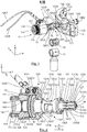
Fig 1 ] lafigure 1 illustre une vue en perspective d'un dispositif de solidarisation selon l'invention ; - [
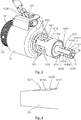
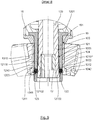
Fig 2 ] lafigure 2 illustre une vue en perspective et en coupe du dispositif de lafigure 1 ; - [
Fig 3 ] lafigure 3 illustre une vue en perspective et en coupe du dispositif de lafigure 2 ; - [
Fig 4 ] lafigure 4 illustre une vue en coupe transversale d'un cône d'expansion d'un dispositif selon l'invention ; - [
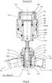
Fig 5 ] lafigure 5 illustre une vue en coupe transversale d'un dispositif selon l'invention, coopérant avec une grille de perçage, dont le cône d'expansion est en position de libération, les billes de verrouillage sont en position de déblocage et la bague expansible est en état relâché ; - [
Fig 6 ] lafigure 6 illustre un détail de lafigure 5 ; - [
Fig 7 ] lafigure 7 illustre une vue en coupe partielle du dispositif de lafigure 5 ; - [
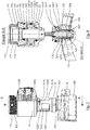
Fig 8 ] lafigure 8 illustre une vue en coupe transversale d'un dispositif selon l'invention, coopérant avec une grille de perçage, dont le cône d'expansion est en position de verrouillage, les billes de verrouillage sont en position de blocage et la bague expansible est en état expansé ; - [
Fig 9 ] lafigure 9 illustre un détail de lafigure 8 ; - [
Fig 10 ] lafigure 10 illustre une vue en coupe partielle du dispositif de lafigure 8 ; - [
Fig 11 ] lafigure 11 illustre le maintien d'une bille de verrouillage dans un orifice d'une bague expansible ; - [
Fig 12 ] lafigure 12 illustre un dispositif de solidarisation selon l'invention fixé à l'extrémité d'un dispositif de perçage.
- [
Fig 1 ] thefigure 1 illustrates a perspective view of a securing device according to the invention; - [
Fig 2 ] thefigure 2 illustrates a perspective and sectional view of the device of thefigure 1 ; - [
Fig 3 ] thefigure 3 illustrates a perspective and sectional view of the device of thefigure 2 ; - [
Fig 4 ] thefigure 4 illustrates a cross-sectional view of an expansion cone of a device according to the invention; - [
Fig 5 ] thefigure 5 illustrates a cross-sectional view of a device according to the invention, cooperating with a drilling grid, the expansion cone of which is in the release position, the locking balls are in the unlocking position and the expandable ring is in state released; - [
Fig 6 ] thefigure 6 illustrates a detail of thefigure 5 ; - [
Fig 7 ] thefigure 7 illustrates a partial sectional view of the device of thefigure 5 ; - [
Fig 8 ] thefigure 8 illustrates a cross-sectional view of a device according to the invention, cooperating with a drilling grid, the expansion cone of which is in the locking position, the locking balls are in the locking position and the expandable ring is in expanded state; - [
Fig 9 ] thefigure 9 illustrates a detail of thefigure 8 ; - [
Fig 10 ] thefigure 10 illustrates a partial sectional view of the device of thefigure 8 ; - [
Fig 11 ] thefigure 11 illustrates the maintenance of a locking ball in an orifice of an expandable ring; - [
Fig 12 ] thefigure 12 illustrates a securing device according to the invention fixed to the end of a piercing device.
On présente en relation avec les
Un tel dispositif de solidarisation peut être mis en œuvre pour assurer la solidarisation de tout type de dispositif de perçage (ou perceuse) à une grille de perçage au rang desquels figurent notamment, mais non exclusivement, les perceuses à paramètres de couple contrôlés et les perceuses à avance automatique.Such a fastening device can be implemented to ensure the fastening of any type of drilling device (or drill) to a drilling grid which ranks including, but not limited to, drills with controlled torque parameters and drills with automatic advance.
En référence à la
Ainsi que cela est représenté, une grille de perçage 13 comprend classiquement une plaque 130 traversée par une pluralité d'alésage de positionnement 131. Une telle plaque 130 peut être plane, incurvée ou présenter tout autre forme adaptée au perçage de l'élément à percer. Elle présente une surface 132 orientée du côté du dispositif de perçage, c'est-à-dire du côté du dispositif de solidarisation, et une surface 133 opposée orientée du côté d'un élément à percer.As shown, a
Les premiers moyens de solidarisation 11 du dispositif à une perceuse comprennent un écrou moleté 110 apte à être vissé sur une portion taraudé 113 du corps 10 ou plus précisément d'un bouchon 14 qui sera décrit plus en détail par la suite. L'écrou 110 peut être serré grâce à une clé à ergot se logeant dans les trous 111.The first means 11 for securing the device to a drill include a
L'écrou moleté 110 présente un épaulement 114.The
Les deuxièmes moyens de solidarisation 12 du dispositif à une grille de perçage comprennent un moyeu expansible à billes qui sera décrit plus en détail par la suite.The second means 12 for securing the device to a drilling grid comprise an expandable ball hub which will be described in more detail below.
Le corps 10 comprend une première portion 100 de fort diamètre prolongée par une deuxième portion 101 de plus faible diamètre.The
La première portion 100 est traversée par un alésage 1220. Cet alésage 1220 est ouvert sur l'extérieur à son extrémité antérieure et refermé au moyen d'un bouchon 14 vissé dans le corps 10.The
Le bouchon 14 porte un joint torique 140 pour assurer une fermeture hermétique de l'alésage 1220.The
Le bouchon 14 est apte à loger une bague intérieure 141 qui y est maintenue entre un épaulement 142 ménagé à l'intérieur du bouchon 14 et un épaulement 114 de l'écrou moleté 110. Cette bague intérieure 141 est conçue pour être solidarisée à l'extrémité du dispositif de perçage à solidariser au dispositif de solidarisation.The
La deuxième portion 101 est traversée latéralement par des lumières 1010 qui permettent l'évacuation des copeaux au cours d'une opération de perçage.The
L'extrémité postérieure de la deuxième portion 101 présente une partie filetée 1011 sur laquelle est vissé un écrou 15 à trous transversaux 150 pour permettre l'introduction d'une clé à ergot afin d'assurer le serrage de l'écrou 15 sur le corps 10.The rear end of the
L'écrou 15 comprend une butée 151 définissant une surface d'appui destinée à venir en appui contre la surface 132 de la grille 13 orientée vers le dispositif de solidarisation lorsque celui-ci est solidarisé à la grille 13.The
Le moyeu expansible à billes comprend notamment :
- une bague expansible 120 ;
un cône d'expansion 121 logé à l'intérieur de la bague expansible 120 ;- des moyens d'entrainement en
translation 122 du cône d'expansion 121 à l'intérieur de la bague d'expansion 120 ; - des billes de verrouillage 123 ;
- une bague de guidage 124.
- an
expandable ring 120; - an
expansion cone 121 housed inside theexpandable ring 120; - means for translational driving 122 of the
expansion cone 121 inside theexpansion ring 120; - locking
balls 123; - a
guide ring 124.
La bague expansible 120 comprend une portion 1200 au contour extérieur essentiellement cylindrique prolongée à l'une de ses extrémités par un épaulement 1201 présentant un méplat (non représenté). Cet épaulement 1201 est logé à l'intérieur d'un alésage 1012 ménagé à l'extrémité postérieure de la deuxième portion 101 du corps et présentant un méplat 1013 de forme complémentaire du méplat de la bague expansible 120. La bague expansible 120 est solidarisée au corps 10 au moyen de l'écrou 15 qui assure son blocage en translation vis-à-vis du corps 10. La bague expansible 120 est bloquée en rotation vis-à-vis du corps 10 par les méplats.The
Des fentes longitudinales 1204 sont ménagées longitudinalement à la périphérie de la portion 1200 de la bague expansible 120 de sorte à permettre à la bague expansible de s'expandre et de se rétracter comme il ressortira plus clairement par la suite.
La bague expansible 120 est traversée par un alésage conique 1202 (ou plus exactement tronconique) ménagé le long d'un axe longitudinal de la bague expansible. L'angle de l'alésage 1202 est tel que l'alésage conique 1202 présente une extrémité de faible diamètre du côté du corps 10 et une extrémité de plus fort diamètre à l'opposée.The
L'extrémité postérieure de la bague expansible 120 est traversée par des orifices radiaux 1203 ménagés selon des axes perpendiculaires à l'axe longitudinal de la bague expansible 120 et répartis de manière uniforme autour de cet axe longitudinal.The rear end of the
L'alésage conique 1202 de la bague expansible 120 loge le cône d'expansion 121. Le cône d'expansion 121 présente un contour périphérique extérieur de forme complémentaire du contour périphérique intérieur de l'alésage conique 1202.The
Le cône d'expansion 121 est monté mobile en translation à l'intérieur de l'alésage conique 1202 selon l'axe longitudinal de celui-ci.The
Des rainures longitudinales 1210 sont ménagées à la surface du cône d'expansion 121.
Ainsi que cela est visible sur la
Les rainures 1210 sont préférentiellement non débouchantes, c'est-à-dire qu'elles ne sont pas ouvertes sur l'extérieur à l'extrémité postérieure du cône d'expansion 121.The
Chaque rainure 1210 loge une bille de verrouillage 123.Each
Les rainures 1210 sont alignées par rapport aux orifices 1203 pour permettre à chaque bille 123 de passer à travers un orifice 1203. Le diamètre extérieur de chaque orifice 1203 est légèrement resserré pour empêcher la bille 123 qui s'y trouve logée d'en sortir complètement. Pour cela, le diamètre extérieur de chaque orifice 1203 peut par exemple présenter un écrouissage 1205 formant saillie à l'intérieur de l'orifice tel que cela est représenté à la
Le cône d'expansion 121 est solidarisé à l'extrémité de la tige creuse 1223 d'un vérin permettant de déplacer en translation de cône d'expansion 121 à l'intérieur de l'alésage conique 1202.The
La tige 1223 est traversée par des lumières périphériques 1221 permettant l'évacuation de copeaux au cours d'une opération de perçage. Ces lumières 1221 s'étendent en regard des lumières 1010 ménagées dans le corps 10.
L'axe longitudinal de la tige 1223 du vérin s'étend co-axialement avec le canon de perçage.The longitudinal axis of the
La tige 1223 porte des goupilles transversales 1222 qui sont chacune logée dans une rainure longitudinale 1014 ménagée à cet effet dans le corps 10. Les goupilles 1222 et les rainures 1014 permettent de bloquer en rotation la tige 1223 par rapport au corps 10 et d'autoriser la translation de la tige 1223 dans le corps 10 le long de son axe longitudinal.The
La tige 1223 porte un piston 1224 logé dans l'alésage 1220. Elle s'étend d'un côté du piston 1224 dans un alésage 1015 ménagé dans le corps 10 et débouchant dans l'alésage 1220. Elle s'étend de l'autre côté du piston 1224 dans un alésage 143 ménagé dans le bouchon 14.The
Les alésages 1015 et 143 présentent chacun une rainure périphérique 1016, 144 logeant un joint torique 1017, 145 permettant d'assurer, avec le joint 140, l'étanchéité de l'alésage 1220 qui constitue le cylindre d'un vérin à l'intérieur duquel le piston 1224 est monté mobile en translation.The
Le piston 1224 délimite à l'intérieur du cylindre 1220 une chambre de verrouillage 12201 et une chambre de libération 12202.The
La surface de la face du piston située dans la chambre de déverrouillage est supérieure à la surface de la face dudit piston située dans ladite chambre de verrouillage.The surface of the face of the piston located in the unlocking chamber is greater than the surface of the face of said piston located in said unlocking chamber locking.
Ceci permet, au cours du déverrouillage du moye expansible, de contrer l'effet du grippage du cône d'expansion dans la bague expansible.This allows, during the unlocking of the expandable hub, to counter the effect of the seizing of the expansion cone in the expandable ring.
Le corps 10 est traversé par un canal de verrouillage 1225 et par un canal de libération 1226 débouchant respectivement dans la chambre de verrouillage 12201 et dans la chambre de libération 12202 et permettant d'alimenter celles-ci en fluide sous pression.The
Le canal de verrouillage 1225 et le canal de libération 1226 sont respectivement reliés à une conduite de verrouillage 1227 et une conduite de libération 1228 destinées à être reliées à des moyens d'alimentation en fluide sous pression.The locking
La bague de guidage 124 est traversée par un alésage intérieur 1240 à l'intérieur duquel est ménagé un logement intérieur périphérique de blocage 1241 se présentant sous la forme d'une gorge. Elle présente un contour extérieur cylindrique prolongé par un épaulement 1242.The
La bague de guidage 124 est destinée à être insérée à l'intérieur d'un alésage de positionnement 131 de la grille de perçage 13. Pour cela, chaque alésage de positionnement 131 comprend deux portions intérieures alésées 1310, 1311 de diamètres différents à l'interface desquelles un épaulement 1312 est formé. L'épaulement 1312 est formé du côté de la grille de perçage 13 situé à l'opposé du côté contre lequel la butée 151 est destinée à venir en appui. La bague de guidage 124 présente ainsi une forme extérieure complémentaire de la forme intérieure de l'alésage de positionnement 131.The
Le cône d'expansion 121 est monté mobile en translation à l'intérieur de l'alésage conique 1202 de la bague expansible 120 selon son axe longitudinal entre au moins :
- une position de libération dans laquelle le cône 121 est déplacé du côté de plus fort diamètre de l'alésage conique 1202 de la bague expansible 120 si bien que celle-ci se trouve dans un état relâché dans lequel son diamètre extérieur est inférieur à celui des alésages intérieurs 1240 des bagues de guidage 124, si elles sont mises en œuvre, ou des alésages de positionnement 131 de la grille de perçage 13 dans le cas contraire, de sorte qu'elle puisse y être introduite ou en être extraite ;
- une position de verrouillage dans laquelle le cône 121 est déplacé du côté de plus faible diamètre de l'alésage conique 1202 de la bague expansible 120 si bien que celle-ci se trouve dans un état expansé dans lequel son diamètre extérieur est augmenté de sorte à maintenir le dispositif de solidarisation solidaire de la grille de perçage 13 par friction de la bague expansible 120 contre les parois internes de l'alésage intérieur 1240 de la bague de guidage 124 dans lequel elle se trouve lorsque des bagues de guidage 124 sont mises en œuvre, ou contre les parois internes de l'alésage de positionnement 131 de la
grille 13 à l'intérieur duquel elle se trouve dans le cas contraire.
- a release position in which the
cone 121 is moved to the side of the larger diameter of theconical bore 1202 of theexpandable ring 120 so that it is in a relaxed state in which its outside diameter is less than that ofinternal bores 1240 of the guide rings 124, if they are used, or positioning bores 131 of thedrilling grid 13 otherwise, so that it can be introduced into or extracted therefrom; - a locking position in which the
cone 121 is moved to the smaller diameter side of theconical bore 1202 of theexpandable ring 120 so that the latter is in an expanded state in which its outer diameter is increased so as to keep the fastening device secured to thedrilling grid 13 by friction of theexpandable ring 120 against the internal walls of theinternal bore 1240 of theguide ring 124 in which it is located when guide rings 124 are used , or against the internal walls of the positioning bore 131 of thegrid 13 inside which it is otherwise.
Lorsqu'une bague de guidage 124 est mise en œuvre, son alésage intérieur constitue un alésage de positionnement.When a
Ainsi, qu'une bague de guidage 124 soit ou non mise en œuvre, la bague expansible 120 est destinée à être logée dans un alésage de positionnement (l'alésage de positionnement 131 de la grille ou l'alésage intérieur 1240 de la bague de guidage 124) solidaire de la grille de perçage 13. Bien entendu, compte le diamètre de l'alésage de positionnement, qu'il soit ménagé dans une bague de guidage ou directement dans la grille, sera déterminé en fonction de la capacité de la bague expansible à s'expandre.Thus, whether a
Le vérin permet de déplacer le piston 1224 et le cône 121 solidaire de sa tige 1223 de l'une à l'autre de ses positions.The jack makes it possible to move the
Le cône d'expansion 121 agit sur les billes de verrouillage 123 pour les placées dans :
- une position de déblocage, prise lorsque le cône 121 se trouve dans sa position de libération, dans laquelle elles ne forment pas saillie à la surface périphérique extérieure de la bague d'expansion 120 ;
- une position de blocage, prise lorsque le cône 121 se trouve dans sa position de verrouillage, dans laquelle elles forment saillie à la surface périphérique extérieure de la bague d'expansion 120 de sorte à pouvoir se loger dans le logement périphérique de blocage 1241 formé dans la bague de guidage 124 et solidaire de l'alésages de positionnement 131 dans lequel elle est logée (ou dans le cas où les bagues de guidage 124 ne sont pas mises en œuvre, dans un logement périphérique de blocage ménagé directement dans les alésages de positionnement 131.
- an unlocking position, taken when the
cone 121 is in its release position, in which they do not protrude from the outer peripheral surface of theexpansion ring 120; - a locking position, taken when the
cone 121 is in its locking position, in which they protrude from the outer peripheral surface of theexpansion ring 120 so as to be able to be housed in theperipheral locking housing 1241 formed in theguide ring 124 and integral with the positioning bores 131 in which it is housed (or in the case where the guide rings 124 are not used, in a peripheral blocking housing formed directly in the positioning bores 131.
Les billes 123 se trouvent contre le premier étage 12100 de la rainure 1210 correspondante dans la position de déblocage et contre le deuxième étage 12101 dans la position de blocage.The
Le dispositif de solidarisation comprend des moyens de régulation des moyens d'entrainement en translation du cône d'expansion, c'est-à-dire du vérin. Ces moyens de régulation sont configurés de sorte que la vitesse de déplacement en translation imprimé au cône d'expansion par le vérin soit inférieure au cours de son passage de la position de libération à la position de blocage à celle au cours de son passage de la position de blocage à la position de libération.The securing device comprises means for regulating the drive means in translation of the expansion cone, that is to say of the jack. These regulation means are configured so that the translational movement speed imparted to the expansion cone by the jack is lower during its passage from the release position to the blocking position than that during its passage from the blocking position to the release position.
Le dispositif de solidarisation est traversé de part en part par un canon de perçage 16 qui permet le déplacement en rotation et en translation d'une broche et de l'outil coupant solidarisé à son extrémité au cours d'une opération de perçage.The fastening device is traversed right through by a piercing
Un brise copeau 17 est placé à l'extrémité postérieure du canon de perçage 16.A
Le fonctionnement d'un dispositif de solidarisation selon l'invention va à présent être décrit.The operation of a securing device according to the invention will now be described.
Un dispositif de solidarisation 1 selon l'invention est en premier lieu solidarisé à l'extrémité d'un dispositif de perçage.A securing
Pour cela, un écrou moleté 110 est enfilé à l'extrémité du carter du dispositif de perçage puis une bague 141 est solidarisée à l'extrémité du carter dispositif de perçage de sorte à être immobile par rapport à celui-ci. Elle peut par exemple être emmanchée à force et/ou collée à l'extrémité du dispositif de perçage. Ainsi, l'écrou moleté 110 est maintenu solidaire du dispositif de perçage par la bague 141. Cet écrou est mobile en rotation par rapport au carter du dispositif de perçage, ainsi qu'en translation jusqu'à venir en appui contre la bague 141.For this, a
Le corps 10 du dispositif de solidarisation est rapproché de l'extrémité du dispositif de perçage de sorte à introduire la bague 141 jusqu'à ce qu'elle vienne en butée contre l'épaulement 142 du bouchon 14. Puis l'écrou moleté 110 est vissé sur la portion filetée 113 de forme complémentaire prévue à cet effet sur le bouchon 14 du dispositif de solidarisation jusqu'à ce que la bague 141 se trouve comprimée entre l'épaulement 142 du bouchon 14 et l'épaulement 114 de l'écrou moleté 110. Le dispositif de solidarisation se trouve alors fixé au dispositif de perçage de telle sorte qu'ils sont immobilisés l'un par rapport à l'autre.The
La
La broche du dispositif de perçage, ainsi éventuellement que l'outil coupant qui pourrait d'ores et déjà y être solidarisé, s'étend(ent) alors dans l'axe longitudinal du dispositif de solidarisation, le cas échéant en partie à l'intérieur du canon de perçage 16.The spindle of the piercing device, as well as possibly the cutting tool which could already be secured to it, then extends (s) in the longitudinal axis of the fastening device, if necessary in part to the inside the
Les conduites de verrouillage 1227 et de libération 1228 sont ensuite raccordées au réseau d'alimentation en fluide sous pression, notamment en air comprimé, du dispositif de perçage.The locking 1227 and release 1228 pipes are then connected to the pressurized fluid supply network, in particular compressed air, of the drilling device.
Le vérin est ensuite piloté de sorte à placer le cône d'expansion 121 dans sa position de libération, les billes de verrouillage 123 dans leur position de déblocage et la bague expansible 120 dans son état relâché s'ils ne se trouvaient pas dans cette position/état (cf.
Pour cela, le fluide sous pression est introduit dans la chambre de libération 12202 via la conduite de libération 1228.For this, the pressurized fluid is introduced into the
Sous l'effet de la pression dans la chambre de libération 12202, le piston 1224 se translate à l'intérieur du cylindre 1220 selon l'axe longitudinal du piston en direction de l'extrémité du dispositif de solidarisation 1 destinée à être solidarisée à une grille de perçage (cf. flèche D).Under the effect of the pressure in the
La tige 1223 du piston suit le déplacement en translation du piston 1224 si bien que le cône d'expansion 121 se translate par rapport à la bague expansible 120 pour se placer dans sa position de libération dans laquelle son extrémité de fort diamètre est éloignée de l'extrémité de fort diamètre de l'alésage conique 1202 de la bague expansible 120. Le cône d'expansion 121 n'agit ainsi pas sur la bague expansible 120. La bague expansible 120 se trouve alors dans son état relâché dans lequel son diamètre extérieur est inférieur au diamètre intérieur des alésages de positionnement 131 de la graille de perçage 13, ou des alésages intérieurs 1240 des bagues de guidage 124 lorsqu'elles sont mises en œuvre.The
Au cours du déplacement du cône d'expansion 121 vers sa position de libération, les billes de verrouillage 123 roulent à la surface du cône d'expansion 121 dans leur rainure respective 1210 d'abord contre le deuxième étage 12101, puis contre la rampe inclinée 12102, pour venir au contact du premier étage 12100.During the displacement of the
Au cours de ce déplacement, les billes de verrouillage 123 se déplacent librement en translation à l'intérieur des orifices radiaux 1203, le long de leur axe longitudinal, jusqu'à se placer dans leur position de déblocage dans laquelle elles ne forment pas saillie à la surface de la bague expansible 120.During this movement, the locking
Les bagues de guidage 124 sont le cas échéant introduites à force dans les alésages de positionnement 131 de la grille de perçage 13, depuis la face 133 de la grille orientée du côté de l'élément à percer, jusqu'à ce que leur épaulement 1242 vienne en appuis contre l'épaulement 1312 de l'alésage de positionnement 131 correspondant.The guide rings 124 are optionally forced into the positioning bores 131 of the
L'extrémité de chaque bague de positionnement 124 orientée du côté de la surface 132 de la grille contre laquelle la butée 151 est destinée à venir en appui forme alors légèrement saillie à cette surface de quelques dixième de millimètre.The end of each
Le dispositif de perçage et le dispositif de solidarisation qui y est fixé sont ensuite déplacés de sorte à introduire la bague expansible 120 dans l'alésage intérieur 1240 de la bague de guidage 124 de la grille de perçage correspondant à l'emplacement auquel il est souhaité de pratiquer un perçage, jusqu'à ce que la butée 151 se trouve en appui contre la bague de guidage 124 si de telles bagues sont mises en œuvre ou contre la surface 132 de la grille de perçage 13 orientée du côté de l'outil de perçage, c'est-à-dire du côté opposé au côté de la grille orienté vers l'élément à percer. Ce déplacement peut être réalisé manuellement par un opérateur ou au moyen d'un bras manipulateur (bras robot) si le dispositif de perçage est solidarisé à l'extrémité d'un tel bras.The piercing device and the fastening device which is attached to it are then moved so as to introduce the expanding
Du fluide sous pression est ensuite admis via la conduite de verrouillage 1127 dans la chambre de verrouillage 12201 pour placer le cône d'expansion 121 dans sa position de verrouillage, la bague expansible dans son état expandu et les billes de verrouillage 123 dans leur position de blocage (cf.
Sous l'effet de la pression dans la chambre de verrouillage 12201, le piston 1224 se translate à l'intérieur du cylindre 1220 selon l'axe longitudinal du piston en direction de l'extrémité du dispositif de solidarisation destinée à être solidarisée à un dispositif de perçage (cf. flèche V).Under the effect of the pressure in the
La tige 1223 du piston suit le déplacement en translation du piston 1224 si bien que le cône d'expansion 121 se translate par rapport à la bague expansible 120 pour se placer dans sa position de verrouillage dans laquelle son extrémité de fort diamètre est rapprochée de l'extrémité de fort diamètre de l'alésage conique 1202 de la bague expansible 120. Le cône d'expansion 121 agit ainsi sur la bague expansible 120. La bague expansible 120 se trouve alors dans son état expansé dans lequel son diamètre extérieur est augmenté jusqu'à ce que la bague expansible 120 vienne se comprimer contre l'alésage intérieur 1240 de la bague de guidage 124 correspondante ou contre la paroi intérieure de l'alésage de positionnement de la grille si aucune bague de guidage n'est mise en œuvre.The
Le dispositif de solidarisation est ainsi maintenu solidaire de la grille de perçage sous l'effet de la friction entre la bague expansible et la bague de guidage ou le cas échéant l'alésage de positionnement.The securing device is thus held integral with the drilling grid under the effect of friction between the expandable ring and the guide ring or, where appropriate, the positioning bore.
Au cours du déplacement du cône d'expansion 121 vers sa position de verrouillage, les billes de verrouillage 123 roulent à la surface du cône d'expansion 121 dans leur rainure respective 1210 d'abord contre le premier étage 12100, puis contre la rampe inclinée 12102, pour venir au contact du deuxième étage 12101.During the movement of the
Au cours de ce déplacement, les billes de verrouillage 123 se déplacent en translation à l'intérieur des orifices radiaux 1203, le long de leur axe longitudinal, jusqu'à se placer dans leur position de blocage dans laquelle elles forment saillie à la surface de la bague expansible 120 si bien qu'elles sont introduites dans le logement intérieur périphérique de blocage 1241 de la bague de guidage 124 correspondante ou directement formé dans l'alésage de positionnement correspondant si aucune bague de guidage n'est mise en œuvre.During this movement, the locking
Les billes de verrouillage 123 associées au logement intérieur périphérique de blocage 1241, permettent d'assurer un blocage en translation du dispositif de solidarisation par rapport à la grille de perçage, et ainsi d'éviter tout déplacement en translation du dispositif de perçage par rapport à la grille le long de l'axe de perçage au cours d'une opération de perçage.The locking
En outre, l'introduction des billes de verrouillage 123 dans le logement intérieur périphérique de blocage 1241 de la bague de guidage 124 tend à induire un effort de compression de l'épaulement 1242 de la bague de guidage 124 contre l'épaulement 1312 de la grille de perçage, ainsi qu'un effort de compression de l'extrémité de la bague de guidage 124 contre la butée 151.In addition, the introduction of the locking
On garantit ainsi la possibilité de réaliser des perçages successifs avec une très bonne répétabilité en terme de profondeur de perçage.This guarantees the possibility of making successive holes with very good repeatability in terms of drilling depth.
Une telle solidarisation ne nécessite pas d'alimenter le vérin avec une pression très élevée. Une pression de l'ordre de 6 bars environ est suffisante.Such an attachment does not require feeding the cylinder with a very high pressure. A pressure of around 6 bars is sufficient.
Une opération de perçage peut ensuite être lancée. Au cours d'une telle opération de perçage, la broche ainsi que l'outil coupant placé à son extrémité se déplacent en translation et en rotation selon un même axe à l'intérieur du canon de perçage 16.A drilling operation can then be launched. During such a drilling operation, the spindle and the cutting tool placed at its end move in translation and in rotation along the same axis inside the
Un brise copeaux 17, placé optionnellement à l'extrémité du canon de perçage 16, permet de briser le copeau formé au cours du perçage et de le guide à l'intérieur du canon de perçage en direction des lumières 1221 et 1010 formées respectivement dans la tige 1223 et dans le corps 10 afin d'être évacués.A
Une buse d'aspiration 18 aura pu être préalablement être solidarisée au corps 10 en regard des lumières 1221 et 1010 pour aspirer les copeaux et les évacuer vers une zone de stockage et/ou de traitement.A
Une bague de protection 19, traversée par des lumières périphériques 190, aura optionnellement pu être interposée entre le corps 10 et la buse d'aspiration 18, pour éviter qu'un opérateur ne puisse introduire les doigts dans les lumières 1221 et 1010.A
Une fois l'opération de perçage achevée, la chambre de déverrouillage 12202 est de nouveau mise sous pression avec de fluide comprimé pour générer le déverrouillage du dispositif selon la procédure décrite plus haut.Once the drilling operation has been completed, the unlocking
L'admission du fluide comprimé dans le vérin est régulée de manière telle que la vitesse du piston pour se déplacer vers sa position de verrouillage est plus élevée que celle pour se déplacer vers sa position de libération. Ceci permet de garantir que l'outil coupant soit sorti de la grille de perçage avant que le dispositif de désolidarisation ne puisse être désolidarisé de la grille de perçage. On évite ainsi de casser l'outil coupant lors de la désolidarisation du dispositif de perçage.The admission of the compressed fluid into the cylinder is regulated in such a way that the speed of the piston to move towards its locking position is higher than that to move to its release position. This makes it possible to guarantee that the cutting tool has come out of the piercing grid before the detaching device can be detached from the piercing grid. This avoids breaking the cutting tool when the drilling device is detached.
Le raccordement des conduites 1227, 1228 se fait préférentiellement en aval de la gâchette d'actionnement ou de la vanne d'actionnement permettant d'alimenter le moteur du dispositif de perçage lorsqu'une opération de perçage est activée.The
De cette façon, le démarrage d'une opération de perçage est synchronisé avec le verrouillage du dispositif de solidarisation de sorte à garantir que l'opération de perçage commence après solidarisation du dispositif de perçage, et inversement.In this way, the start of a drilling operation is synchronized with the locking of the fastening device so as to guarantee that the drilling operation begins after the fastening of the drilling device, and vice versa.
Plutôt que de mettre en œuvre des billes pour bloquer le déplacement en translation du dispositif de solidarisation par rapport à la grille, une bague expansible à collerette pourrait être mise en œuvre. Cette collerette pourrait venir se loger dans un logement de forme complémentaire formé directement dans un alésage de positionnement ou dans une bague de guidage comme les billes de verrouillage. Alternativement, cette collerette pourrait venir en appui contre la surface de la grille placée du côté de l'élément à percer.Rather than using balls to block movement by translation of the securing device relative to the grid, an expandable collar ring could be implemented. This flange could be housed in a housing of complementary shape formed directly in a positioning bore or in a guide ring like the locking balls. Alternatively, this flange could bear against the surface of the grid placed on the side of the element to be drilled.
Les billes de verrouillage et la collerette constituent des moyens de blocage en translation du dispositif de solidarisation par rapport à la grille selon l'axe de perçage.The locking balls and the flange constitute means for blocking in translation the fastening device relative to the grid along the drilling axis.
Dans une variante, le sens de déplacement du cône d'expansion pour passer de sa position de libération à sa position de verrouillage pourra être inversée. Dans ce cas, il passera de sa position de libération à sa position de verrouillage en étant translaté en direction de la surface de la grille de perçage orientée vers l'élément à percer.Alternatively, the direction of movement of the expansion cone to move from its release position to its locking position may be reversed. In this case, it will pass from its release position to its locking position by being translated towards the surface of the drilling grid oriented towards the element to be drilled.
Au cours de leur passage de leur position de déblocage à leur position de blocage, les billes pourront en premier lieu venir au contact du bord du logement périphérique de blocage orienté vers le dispositif de perçage. Les billes viendront ainsi se loger dans le logement périphérique de blocage en générant un effort axial ayant tendance à comprimer la butée contre la grille ou la bague de guidage.During their passage from their unlocking position to their blocking position, the balls may first of all come into contact with the edge of the peripheral blocking housing oriented towards the piercing device. The balls will thus be housed in the peripheral blocking housing by generating an axial force which tends to compress the stop against the grid or the guide ring.
De manière alternative, les billes pourront directement se loger dans logement périphérique de blocage sans générer d'effort axial.Alternatively, the balls can be directly housed in peripheral blocking housing without generating axial force.
Claims (16)
Applications Claiming Priority (1)
| Application Number | Priority Date | Filing Date | Title |
|---|---|---|---|
| FR1872722A FR3089441B1 (en) | 2018-12-11 | 2018-12-11 | Device for securing a drilling device to a drilling grid comprising an expanding ball hub |
Publications (2)
| Publication Number | Publication Date |
|---|---|
| EP3666432A1 true EP3666432A1 (en) | 2020-06-17 |
| EP3666432B1 EP3666432B1 (en) | 2021-11-03 |
Family
ID=66542357
Family Applications (1)
| Application Number | Title | Priority Date | Filing Date |
|---|---|---|---|
| EP19212196.0A Active EP3666432B1 (en) | 2018-12-11 | 2019-11-28 | Device for securing a boring device to a boring grate comprising an expandable ball hub |
Country Status (3)
| Country | Link |
|---|---|
| US (1) | US11298755B2 (en) |
| EP (1) | EP3666432B1 (en) |
| FR (1) | FR3089441B1 (en) |
Citations (5)
| Publication number | Priority date | Publication date | Assignee | Title |
|---|---|---|---|---|
| US5395187A (en) * | 1993-11-22 | 1995-03-07 | Mcdonnell Douglas Corporation | Method and apparatus for attaching a drill motor to a drill plate with a clamping device having an expandable collet |
| US5482411A (en) * | 1994-12-22 | 1996-01-09 | Mcdonnell Douglas Corporation | Method and apparatus for securely clamping a drill motor to a drill plate |
| US20040223821A1 (en) * | 2003-05-06 | 2004-11-11 | The Boeing Company | Locking nosepiece and template |
| WO2008133586A1 (en) * | 2007-04-27 | 2008-11-06 | Novator Ab | Fixation device for a portable drilling unit |
| US20120328382A1 (en) * | 2011-06-22 | 2012-12-27 | Sugino Machine Limited | Clamping device, clamping method, and hole drilling method |
Family Cites Families (8)
| Publication number | Priority date | Publication date | Assignee | Title |
|---|---|---|---|---|
| US2839953A (en) * | 1955-10-24 | 1958-06-24 | Boeing Co | Drill motor collet mounts |
| US2935905A (en) * | 1956-12-10 | 1960-05-10 | Winslow Product Engineering Co | Collet foot attachment for pneumatic power drill |
| FR2562179B1 (en) * | 1984-04-02 | 1986-08-14 | Recoules Fils | DEVICE FOR AUTOMATICALLY FIXING TOOLS ONTO A SUPPORT |
| US5628592A (en) * | 1995-08-31 | 1997-05-13 | Cooper Industries, Inc. | Two-piece concentric collet |
| US6012877A (en) * | 1996-12-13 | 2000-01-11 | The Boeing Company | Self-centering end effector |
| FR2934966B1 (en) * | 2008-08-12 | 2010-09-17 | Airbus France | DRILLING SYSTEM AND METHOD |
| FR2969518B1 (en) * | 2010-12-22 | 2014-02-21 | Cooper Power Tools Sas | DEVICE FOR POSITIONING A WORKING MACHINE ON A SUPPORT WITH RESPECT TO A WORKPIECE |
| FR3022167B1 (en) * | 2014-06-17 | 2016-07-15 | Cinetic Machining | DRILLING AND / OR BORING MACHINE, IN PARTICULAR FOR PARTS COMPRISING AIRCRAFT STRUCTURES |
-
2018
- 2018-12-11 FR FR1872722A patent/FR3089441B1/en not_active Expired - Fee Related
-
2019
- 2019-11-28 EP EP19212196.0A patent/EP3666432B1/en active Active
- 2019-12-10 US US16/709,282 patent/US11298755B2/en active Active
Patent Citations (5)
| Publication number | Priority date | Publication date | Assignee | Title |
|---|---|---|---|---|
| US5395187A (en) * | 1993-11-22 | 1995-03-07 | Mcdonnell Douglas Corporation | Method and apparatus for attaching a drill motor to a drill plate with a clamping device having an expandable collet |
| US5482411A (en) * | 1994-12-22 | 1996-01-09 | Mcdonnell Douglas Corporation | Method and apparatus for securely clamping a drill motor to a drill plate |
| US20040223821A1 (en) * | 2003-05-06 | 2004-11-11 | The Boeing Company | Locking nosepiece and template |
| WO2008133586A1 (en) * | 2007-04-27 | 2008-11-06 | Novator Ab | Fixation device for a portable drilling unit |
| US20120328382A1 (en) * | 2011-06-22 | 2012-12-27 | Sugino Machine Limited | Clamping device, clamping method, and hole drilling method |
Also Published As
| Publication number | Publication date |
|---|---|
| FR3089441A1 (en) | 2020-06-12 |
| US20200180046A1 (en) | 2020-06-11 |
| FR3089441B1 (en) | 2021-04-02 |
| US11298755B2 (en) | 2022-04-12 |
| EP3666432B1 (en) | 2021-11-03 |
Similar Documents
| Publication | Publication Date | Title |
|---|---|---|
| EP2105249B1 (en) | Machining tool with automatic feed and machining method | |
| EP1023522B1 (en) | Core drill | |
| EP2790860B1 (en) | Machining process | |
| FR2912672A1 (en) | METHOD FOR ASSEMBLING TWO ASSEMBLIES, SUCH AS AIRCRAFT FUSELAGE ASSEMBLIES | |
| FR2738281A1 (en) | EXPLOSION PREVENTION SYSTEM EQUIPPED WITH BELIER LATCHES | |
| FR2491807A1 (en) | DEVICE FOR TAKING PARTS SUCCESSIVELY TIGHTENING AND LOCKING | |
| FR2482887A1 (en) | INTEGRATED TOOL HOLDER WITH ROTATING TOOL MACHINE TOOL MACHINE TOOL | |
| EP0340369B1 (en) | Device for assembling toolholders and tools having conical and facial contact surfaces particularly for machining centers with automatic or manual tool changers | |
| EP2285534B1 (en) | Equipment for placing a pin bushing, and kit including same | |
| EP0346231B1 (en) | Drill, especially for a programmable machine | |
| EP3666432B1 (en) | Device for securing a boring device to a boring grate comprising an expandable ball hub | |
| EP2498938B1 (en) | Tapping unit with protection means | |
| FR2972664A1 (en) | QUICK CLAMP SPINDLE | |
| WO2004014653A2 (en) | Improved printing machines | |
| FR3069472B1 (en) | DRILL COMPRISING MECHANICAL MEANS FOR REGULATING THE LUBRICATION FLOW IN ACCORDANCE WITH CUTTING EFFORTS | |
| EP1844897A1 (en) | System for extracting chips and/or dust for a milling head equipped with automatic tool changing | |
| EP3306167B1 (en) | Quick coupling | |
| CH684391A5 (en) | Method and apparatus for implementing an O-ring in a groove. | |
| FR3065179A1 (en) | EFFECTOR DEVICE FOR ORBITAL DRILLING, FOR MOUNTING ON A ROBOT ARM OR ON AN AUTOMATIC PORTABLE UNIT | |
| CH646078A5 (en) | DEVICE FOR FIXING A CUTTING INSERT ON A TOOL HOLDER. | |
| FR2653363A1 (en) | Machining assembly for making a multiplicity of holes in a structure, such as an aircraft cell, using a grid equipped with barrels and at least one drilling machine | |
| FR3117053A1 (en) | drilling device with spindle uncoupling and braking means | |
| EP3572173A1 (en) | Guiding barrel for a cutting tool, associated drilling machine and system, use of the drilling system and method for maintaining the drilling machine | |
| FR3033510A1 (en) | TRANSMISSION DEVICE ADAPTED TO TRANSFORM A ROTATION MOVEMENT OF A MOTOR SHAFT OF A MACHINE SUCH AS A DRILL INTO A ROTATION MOVEMENT AND TRANSLATION OF A CHUCK | |
| FR2488826A1 (en) | Pneumatically driven screw driving tool - has adjustable screwing depth stop controlling air supply cut=off valve via hand-operated pilot valve |
Legal Events
| Date | Code | Title | Description |
|---|---|---|---|
| PUAI | Public reference made under article 153(3) epc to a published international application that has entered the european phase |
Free format text: ORIGINAL CODE: 0009012 |
|
| STAA | Information on the status of an ep patent application or granted ep patent |
Free format text: STATUS: THE APPLICATION HAS BEEN PUBLISHED |
|
| AK | Designated contracting states |
Kind code of ref document: A1 Designated state(s): AL AT BE BG CH CY CZ DE DK EE ES FI FR GB GR HR HU IE IS IT LI LT LU LV MC MK MT NL NO PL PT RO RS SE SI SK SM TR |
|
| AX | Request for extension of the european patent |
Extension state: BA ME |
|
| STAA | Information on the status of an ep patent application or granted ep patent |
Free format text: STATUS: REQUEST FOR EXAMINATION WAS MADE |
|
| 17P | Request for examination filed |
Effective date: 20200612 |
|
| RBV | Designated contracting states (corrected) |
Designated state(s): AL AT BE BG CH CY CZ DE DK EE ES FI FR GB GR HR HU IE IS IT LI LT LU LV MC MK MT NL NO PL PT RO RS SE SI SK SM TR |
|
| GRAP | Despatch of communication of intention to grant a patent |
Free format text: ORIGINAL CODE: EPIDOSNIGR1 |
|
| STAA | Information on the status of an ep patent application or granted ep patent |
Free format text: STATUS: GRANT OF PATENT IS INTENDED |
|
| INTG | Intention to grant announced |
Effective date: 20210115 |
|
| GRAS | Grant fee paid |
Free format text: ORIGINAL CODE: EPIDOSNIGR3 |
|
| GRAJ | Information related to disapproval of communication of intention to grant by the applicant or resumption of examination proceedings by the epo deleted |
Free format text: ORIGINAL CODE: EPIDOSDIGR1 |
|
| GRAL | Information related to payment of fee for publishing/printing deleted |
Free format text: ORIGINAL CODE: EPIDOSDIGR3 |
|
| STAA | Information on the status of an ep patent application or granted ep patent |
Free format text: STATUS: REQUEST FOR EXAMINATION WAS MADE |
|
| GRAP | Despatch of communication of intention to grant a patent |
Free format text: ORIGINAL CODE: EPIDOSNIGR1 |
|
| INTC | Intention to grant announced (deleted) | ||
| STAA | Information on the status of an ep patent application or granted ep patent |
Free format text: STATUS: GRANT OF PATENT IS INTENDED |
|
| INTG | Intention to grant announced |
Effective date: 20210609 |
|
| GRAA | (expected) grant |
Free format text: ORIGINAL CODE: 0009210 |
|
| STAA | Information on the status of an ep patent application or granted ep patent |
Free format text: STATUS: THE PATENT HAS BEEN GRANTED |
|
| AK | Designated contracting states |
Kind code of ref document: B1 Designated state(s): AL AT BE BG CH CY CZ DE DK EE ES FI FR GB GR HR HU IE IS IT LI LT LU LV MC MK MT NL NO PL PT RO RS SE SI SK SM TR |
|
| REG | Reference to a national code |
Ref country code: GB Ref legal event code: FG4D Free format text: NOT ENGLISH |
|
| REG | Reference to a national code |
Ref country code: AT Ref legal event code: REF Ref document number: 1443523 Country of ref document: AT Kind code of ref document: T Effective date: 20211115 Ref country code: CH Ref legal event code: EP |
|
| REG | Reference to a national code |
Ref country code: IE Ref legal event code: FG4D Free format text: LANGUAGE OF EP DOCUMENT: FRENCH |
|
| REG | Reference to a national code |
Ref country code: DE Ref legal event code: R096 Ref document number: 602019008931 Country of ref document: DE |
|
| REG | Reference to a national code |
Ref country code: LT Ref legal event code: MG9D |
|
| REG | Reference to a national code |
Ref country code: NL Ref legal event code: MP Effective date: 20211103 |
|
| REG | Reference to a national code |
Ref country code: AT Ref legal event code: MK05 Ref document number: 1443523 Country of ref document: AT Kind code of ref document: T Effective date: 20211103 |
|
| PG25 | Lapsed in a contracting state [announced via postgrant information from national office to epo] |
Ref country code: RS Free format text: LAPSE BECAUSE OF FAILURE TO SUBMIT A TRANSLATION OF THE DESCRIPTION OR TO PAY THE FEE WITHIN THE PRESCRIBED TIME-LIMIT Effective date: 20211103 Ref country code: LT Free format text: LAPSE BECAUSE OF FAILURE TO SUBMIT A TRANSLATION OF THE DESCRIPTION OR TO PAY THE FEE WITHIN THE PRESCRIBED TIME-LIMIT Effective date: 20211103 Ref country code: FI Free format text: LAPSE BECAUSE OF FAILURE TO SUBMIT A TRANSLATION OF THE DESCRIPTION OR TO PAY THE FEE WITHIN THE PRESCRIBED TIME-LIMIT Effective date: 20211103 Ref country code: BG Free format text: LAPSE BECAUSE OF FAILURE TO SUBMIT A TRANSLATION OF THE DESCRIPTION OR TO PAY THE FEE WITHIN THE PRESCRIBED TIME-LIMIT Effective date: 20220203 Ref country code: AT Free format text: LAPSE BECAUSE OF FAILURE TO SUBMIT A TRANSLATION OF THE DESCRIPTION OR TO PAY THE FEE WITHIN THE PRESCRIBED TIME-LIMIT Effective date: 20211103 |
|
| PG25 | Lapsed in a contracting state [announced via postgrant information from national office to epo] |
Ref country code: IS Free format text: LAPSE BECAUSE OF FAILURE TO SUBMIT A TRANSLATION OF THE DESCRIPTION OR TO PAY THE FEE WITHIN THE PRESCRIBED TIME-LIMIT Effective date: 20220303 Ref country code: SE Free format text: LAPSE BECAUSE OF FAILURE TO SUBMIT A TRANSLATION OF THE DESCRIPTION OR TO PAY THE FEE WITHIN THE PRESCRIBED TIME-LIMIT Effective date: 20211103 Ref country code: PT Free format text: LAPSE BECAUSE OF FAILURE TO SUBMIT A TRANSLATION OF THE DESCRIPTION OR TO PAY THE FEE WITHIN THE PRESCRIBED TIME-LIMIT Effective date: 20220303 Ref country code: PL Free format text: LAPSE BECAUSE OF FAILURE TO SUBMIT A TRANSLATION OF THE DESCRIPTION OR TO PAY THE FEE WITHIN THE PRESCRIBED TIME-LIMIT Effective date: 20211103 Ref country code: NO Free format text: LAPSE BECAUSE OF FAILURE TO SUBMIT A TRANSLATION OF THE DESCRIPTION OR TO PAY THE FEE WITHIN THE PRESCRIBED TIME-LIMIT Effective date: 20220203 Ref country code: NL Free format text: LAPSE BECAUSE OF FAILURE TO SUBMIT A TRANSLATION OF THE DESCRIPTION OR TO PAY THE FEE WITHIN THE PRESCRIBED TIME-LIMIT Effective date: 20211103 Ref country code: LV Free format text: LAPSE BECAUSE OF FAILURE TO SUBMIT A TRANSLATION OF THE DESCRIPTION OR TO PAY THE FEE WITHIN THE PRESCRIBED TIME-LIMIT Effective date: 20211103 Ref country code: HR Free format text: LAPSE BECAUSE OF FAILURE TO SUBMIT A TRANSLATION OF THE DESCRIPTION OR TO PAY THE FEE WITHIN THE PRESCRIBED TIME-LIMIT Effective date: 20211103 Ref country code: GR Free format text: LAPSE BECAUSE OF FAILURE TO SUBMIT A TRANSLATION OF THE DESCRIPTION OR TO PAY THE FEE WITHIN THE PRESCRIBED TIME-LIMIT Effective date: 20220204 Ref country code: ES Free format text: LAPSE BECAUSE OF FAILURE TO SUBMIT A TRANSLATION OF THE DESCRIPTION OR TO PAY THE FEE WITHIN THE PRESCRIBED TIME-LIMIT Effective date: 20211103 |
|
| PG25 | Lapsed in a contracting state [announced via postgrant information from national office to epo] |
Ref country code: SM Free format text: LAPSE BECAUSE OF FAILURE TO SUBMIT A TRANSLATION OF THE DESCRIPTION OR TO PAY THE FEE WITHIN THE PRESCRIBED TIME-LIMIT Effective date: 20211103 Ref country code: SK Free format text: LAPSE BECAUSE OF FAILURE TO SUBMIT A TRANSLATION OF THE DESCRIPTION OR TO PAY THE FEE WITHIN THE PRESCRIBED TIME-LIMIT Effective date: 20211103 Ref country code: RO Free format text: LAPSE BECAUSE OF FAILURE TO SUBMIT A TRANSLATION OF THE DESCRIPTION OR TO PAY THE FEE WITHIN THE PRESCRIBED TIME-LIMIT Effective date: 20211103 Ref country code: LU Free format text: LAPSE BECAUSE OF NON-PAYMENT OF DUE FEES Effective date: 20211128 Ref country code: EE Free format text: LAPSE BECAUSE OF FAILURE TO SUBMIT A TRANSLATION OF THE DESCRIPTION OR TO PAY THE FEE WITHIN THE PRESCRIBED TIME-LIMIT Effective date: 20211103 Ref country code: DK Free format text: LAPSE BECAUSE OF FAILURE TO SUBMIT A TRANSLATION OF THE DESCRIPTION OR TO PAY THE FEE WITHIN THE PRESCRIBED TIME-LIMIT Effective date: 20211103 Ref country code: CZ Free format text: LAPSE BECAUSE OF FAILURE TO SUBMIT A TRANSLATION OF THE DESCRIPTION OR TO PAY THE FEE WITHIN THE PRESCRIBED TIME-LIMIT Effective date: 20211103 Ref country code: BE Free format text: LAPSE BECAUSE OF NON-PAYMENT OF DUE FEES Effective date: 20211130 |
|
| REG | Reference to a national code |
Ref country code: BE Ref legal event code: MM Effective date: 20211130 |
|
| REG | Reference to a national code |
Ref country code: DE Ref legal event code: R097 Ref document number: 602019008931 Country of ref document: DE |
|
| PG25 | Lapsed in a contracting state [announced via postgrant information from national office to epo] |
Ref country code: MC Free format text: LAPSE BECAUSE OF FAILURE TO SUBMIT A TRANSLATION OF THE DESCRIPTION OR TO PAY THE FEE WITHIN THE PRESCRIBED TIME-LIMIT Effective date: 20211103 |
|
| PLBE | No opposition filed within time limit |
Free format text: ORIGINAL CODE: 0009261 |
|
| STAA | Information on the status of an ep patent application or granted ep patent |
Free format text: STATUS: NO OPPOSITION FILED WITHIN TIME LIMIT |
|
| 26N | No opposition filed |
Effective date: 20220804 |
|
| PG25 | Lapsed in a contracting state [announced via postgrant information from national office to epo] |
Ref country code: IE Free format text: LAPSE BECAUSE OF NON-PAYMENT OF DUE FEES Effective date: 20211128 Ref country code: AL Free format text: LAPSE BECAUSE OF FAILURE TO SUBMIT A TRANSLATION OF THE DESCRIPTION OR TO PAY THE FEE WITHIN THE PRESCRIBED TIME-LIMIT Effective date: 20211103 |
|
| PG25 | Lapsed in a contracting state [announced via postgrant information from national office to epo] |
Ref country code: SI Free format text: LAPSE BECAUSE OF FAILURE TO SUBMIT A TRANSLATION OF THE DESCRIPTION OR TO PAY THE FEE WITHIN THE PRESCRIBED TIME-LIMIT Effective date: 20211103 |
|
| PG25 | Lapsed in a contracting state [announced via postgrant information from national office to epo] |
Ref country code: IT Free format text: LAPSE BECAUSE OF FAILURE TO SUBMIT A TRANSLATION OF THE DESCRIPTION OR TO PAY THE FEE WITHIN THE PRESCRIBED TIME-LIMIT Effective date: 20211103 |
|
| PG25 | Lapsed in a contracting state [announced via postgrant information from national office to epo] |
Ref country code: CY Free format text: LAPSE BECAUSE OF FAILURE TO SUBMIT A TRANSLATION OF THE DESCRIPTION OR TO PAY THE FEE WITHIN THE PRESCRIBED TIME-LIMIT Effective date: 20211103 |
|
| REG | Reference to a national code |
Ref country code: CH Ref legal event code: PL |
|
| PG25 | Lapsed in a contracting state [announced via postgrant information from national office to epo] |
Ref country code: LI Free format text: LAPSE BECAUSE OF NON-PAYMENT OF DUE FEES Effective date: 20221130 Ref country code: HU Free format text: LAPSE BECAUSE OF FAILURE TO SUBMIT A TRANSLATION OF THE DESCRIPTION OR TO PAY THE FEE WITHIN THE PRESCRIBED TIME-LIMIT; INVALID AB INITIO Effective date: 20191128 Ref country code: CH Free format text: LAPSE BECAUSE OF NON-PAYMENT OF DUE FEES Effective date: 20221130 |
|
| PGFP | Annual fee paid to national office [announced via postgrant information from national office to epo] |
Ref country code: GB Payment date: 20231127 Year of fee payment: 5 |
|
| PGFP | Annual fee paid to national office [announced via postgrant information from national office to epo] |
Ref country code: FR Payment date: 20231128 Year of fee payment: 5 Ref country code: DE Payment date: 20231129 Year of fee payment: 5 |
|
| PG25 | Lapsed in a contracting state [announced via postgrant information from national office to epo] |
Ref country code: MK Free format text: LAPSE BECAUSE OF FAILURE TO SUBMIT A TRANSLATION OF THE DESCRIPTION OR TO PAY THE FEE WITHIN THE PRESCRIBED TIME-LIMIT Effective date: 20211103 |