EP2105249B1 - Machining tool with automatic feed and machining method - Google Patents
Machining tool with automatic feed and machining method Download PDFInfo
- Publication number
- EP2105249B1 EP2105249B1 EP09155921A EP09155921A EP2105249B1 EP 2105249 B1 EP2105249 B1 EP 2105249B1 EP 09155921 A EP09155921 A EP 09155921A EP 09155921 A EP09155921 A EP 09155921A EP 2105249 B1 EP2105249 B1 EP 2105249B1
- Authority
- EP
- European Patent Office
- Prior art keywords
- spindle
- dog
- engagement
- machining tool
- driving
- Prior art date
- Legal status (The legal status is an assumption and is not a legal conclusion. Google has not performed a legal analysis and makes no representation as to the accuracy of the status listed.)
- Expired - Fee Related
Links
Images


Classifications
-
- B—PERFORMING OPERATIONS; TRANSPORTING
- B23—MACHINE TOOLS; METAL-WORKING NOT OTHERWISE PROVIDED FOR
- B23Q—DETAILS, COMPONENTS, OR ACCESSORIES FOR MACHINE TOOLS, e.g. ARRANGEMENTS FOR COPYING OR CONTROLLING; MACHINE TOOLS IN GENERAL CHARACTERISED BY THE CONSTRUCTION OF PARTICULAR DETAILS OR COMPONENTS; COMBINATIONS OR ASSOCIATIONS OF METAL-WORKING MACHINES, NOT DIRECTED TO A PARTICULAR RESULT
- B23Q5/00—Driving or feeding mechanisms; Control arrangements therefor
- B23Q5/22—Feeding members carrying tools or work
- B23Q5/32—Feeding working-spindles
- B23Q5/326—Feeding working-spindles screw-operated
-
- B—PERFORMING OPERATIONS; TRANSPORTING
- B23—MACHINE TOOLS; METAL-WORKING NOT OTHERWISE PROVIDED FOR
- B23Q—DETAILS, COMPONENTS, OR ACCESSORIES FOR MACHINE TOOLS, e.g. ARRANGEMENTS FOR COPYING OR CONTROLLING; MACHINE TOOLS IN GENERAL CHARACTERISED BY THE CONSTRUCTION OF PARTICULAR DETAILS OR COMPONENTS; COMBINATIONS OR ASSOCIATIONS OF METAL-WORKING MACHINES, NOT DIRECTED TO A PARTICULAR RESULT
- B23Q5/00—Driving or feeding mechanisms; Control arrangements therefor
- B23Q5/22—Feeding members carrying tools or work
- B23Q5/34—Feeding other members supporting tools or work, e.g. saddles, tool-slides, through mechanical transmission
- B23Q5/38—Feeding other members supporting tools or work, e.g. saddles, tool-slides, through mechanical transmission feeding continuously
- B23Q5/40—Feeding other members supporting tools or work, e.g. saddles, tool-slides, through mechanical transmission feeding continuously by feed shaft, e.g. lead screw
- B23Q5/402—Feeding other members supporting tools or work, e.g. saddles, tool-slides, through mechanical transmission feeding continuously by feed shaft, e.g. lead screw in which screw or nut can both be driven
-
- Y—GENERAL TAGGING OF NEW TECHNOLOGICAL DEVELOPMENTS; GENERAL TAGGING OF CROSS-SECTIONAL TECHNOLOGIES SPANNING OVER SEVERAL SECTIONS OF THE IPC; TECHNICAL SUBJECTS COVERED BY FORMER USPC CROSS-REFERENCE ART COLLECTIONS [XRACs] AND DIGESTS
- Y10—TECHNICAL SUBJECTS COVERED BY FORMER USPC
- Y10T—TECHNICAL SUBJECTS COVERED BY FORMER US CLASSIFICATION
- Y10T408/00—Cutting by use of rotating axially moving tool
- Y10T408/03—Processes
-
- Y—GENERAL TAGGING OF NEW TECHNOLOGICAL DEVELOPMENTS; GENERAL TAGGING OF CROSS-SECTIONAL TECHNOLOGIES SPANNING OVER SEVERAL SECTIONS OF THE IPC; TECHNICAL SUBJECTS COVERED BY FORMER USPC CROSS-REFERENCE ART COLLECTIONS [XRACs] AND DIGESTS
- Y10—TECHNICAL SUBJECTS COVERED BY FORMER USPC
- Y10T—TECHNICAL SUBJECTS COVERED BY FORMER US CLASSIFICATION
- Y10T408/00—Cutting by use of rotating axially moving tool
- Y10T408/16—Cutting by use of rotating axially moving tool with control means energized in response to activator stimulated by condition sensor
- Y10T408/17—Cutting by use of rotating axially moving tool with control means energized in response to activator stimulated by condition sensor to control infeed
-
- Y—GENERAL TAGGING OF NEW TECHNOLOGICAL DEVELOPMENTS; GENERAL TAGGING OF CROSS-SECTIONAL TECHNOLOGIES SPANNING OVER SEVERAL SECTIONS OF THE IPC; TECHNICAL SUBJECTS COVERED BY FORMER USPC CROSS-REFERENCE ART COLLECTIONS [XRACs] AND DIGESTS
- Y10—TECHNICAL SUBJECTS COVERED BY FORMER USPC
- Y10T—TECHNICAL SUBJECTS COVERED BY FORMER US CLASSIFICATION
- Y10T408/00—Cutting by use of rotating axially moving tool
- Y10T408/18—Cutting by use of rotating axially moving tool with stopping upon completion of prescribed operation
- Y10T408/20—Responsive to condition of work or product
-
- Y—GENERAL TAGGING OF NEW TECHNOLOGICAL DEVELOPMENTS; GENERAL TAGGING OF CROSS-SECTIONAL TECHNOLOGIES SPANNING OVER SEVERAL SECTIONS OF THE IPC; TECHNICAL SUBJECTS COVERED BY FORMER USPC CROSS-REFERENCE ART COLLECTIONS [XRACs] AND DIGESTS
- Y10—TECHNICAL SUBJECTS COVERED BY FORMER USPC
- Y10T—TECHNICAL SUBJECTS COVERED BY FORMER US CLASSIFICATION
- Y10T408/00—Cutting by use of rotating axially moving tool
- Y10T408/55—Cutting by use of rotating axially moving tool with work-engaging structure other than Tool or tool-support
- Y10T408/561—Having tool-opposing, work-engaging surface
- Y10T408/5626—Having tool-opposing, work-engaging surface with means to move Tool relative to other work-engaging structure along tool-axis
-
- Y—GENERAL TAGGING OF NEW TECHNOLOGICAL DEVELOPMENTS; GENERAL TAGGING OF CROSS-SECTIONAL TECHNOLOGIES SPANNING OVER SEVERAL SECTIONS OF THE IPC; TECHNICAL SUBJECTS COVERED BY FORMER USPC CROSS-REFERENCE ART COLLECTIONS [XRACs] AND DIGESTS
- Y10—TECHNICAL SUBJECTS COVERED BY FORMER USPC
- Y10T—TECHNICAL SUBJECTS COVERED BY FORMER US CLASSIFICATION
- Y10T408/00—Cutting by use of rotating axially moving tool
- Y10T408/68—Tool or tool-support with thrust-applying machine-engaging screw
-
- Y—GENERAL TAGGING OF NEW TECHNOLOGICAL DEVELOPMENTS; GENERAL TAGGING OF CROSS-SECTIONAL TECHNOLOGIES SPANNING OVER SEVERAL SECTIONS OF THE IPC; TECHNICAL SUBJECTS COVERED BY FORMER USPC CROSS-REFERENCE ART COLLECTIONS [XRACs] AND DIGESTS
- Y10—TECHNICAL SUBJECTS COVERED BY FORMER USPC
- Y10T—TECHNICAL SUBJECTS COVERED BY FORMER US CLASSIFICATION
- Y10T408/00—Cutting by use of rotating axially moving tool
- Y10T408/70—Tool or tool-support with torque-applying clutch
-
- Y—GENERAL TAGGING OF NEW TECHNOLOGICAL DEVELOPMENTS; GENERAL TAGGING OF CROSS-SECTIONAL TECHNOLOGIES SPANNING OVER SEVERAL SECTIONS OF THE IPC; TECHNICAL SUBJECTS COVERED BY FORMER USPC CROSS-REFERENCE ART COLLECTIONS [XRACs] AND DIGESTS
- Y10—TECHNICAL SUBJECTS COVERED BY FORMER USPC
- Y10T—TECHNICAL SUBJECTS COVERED BY FORMER US CLASSIFICATION
- Y10T408/00—Cutting by use of rotating axially moving tool
- Y10T408/73—Tool or tool-support with torque-applying spline
Definitions
- the present invention relates to a machining machine according to the preamble of claim 1.
- the invention applies for example to pneumatic drilling machines used in aircraft construction.
- a machine of the aforementioned type is known for example from EP-A-1618978 .
- the drive mechanism of such a machine is called "mechanical advance” in French or “positive feed drill” in English.
- a single motor then ensures, via the drive mechanism, driving the spindle in rotation about its axis and simultaneously its advance or recoil by translation along its axis.
- the spindle advance per revolution is constant.
- variations in the speed of the motor have no effect on the advance per revolution.
- the thickness of the formed chips therefore remains constant and promotes the surface quality and the precision of the bores pierced by such a machine.
- An object of the invention is to provide a machine of the aforementioned type, which operates at high rotational speed and is reliable.
- the subject of the invention is a machine according to claim 1.
- the machine may comprise one or more of the features of dependent claims 2 to 13, taken alone or in any technically possible combination.
- the invention also relates to a machining method according to claims 14 or 15.
- the spindle 4 is received in the casing 2 rotatably about its axis A and in translation along this axis A.
- the casing 2 is provided with a lubrication system 18.
- a drilling tool in the form of a forest is for example removably mounted at the lower end 22 of the spindle 4.
- the lubrication system 18 lubricates the cutting edge. the tool during machining.
- the output shaft 24 of the motor 6 carries a conical output gear 26 which meshes with an input conical pinion 28 of axis B belonging to the drive mechanism 12.
- the motor 6 is arranged substantially at right angles to the pin 4. However, it could be substantially parallel to the latter, as explained for example in the document FR-2 829 952 .
- the first gear 32 is threaded onto the spindle 4 and is integral in rotation with the latter.
- the pin 4 is movable in translation relative to the pinion 32 along the axis A. This connection between the pin 4 and the first pinion 32 is for example obtained by means of splines.
- the second gear 34 comprises an internal thread cooperating with an external thread of the spindle 4.
- the second gear 34 is thus screwed, in known manner, onto the spindle 4.
- the second gear 34 is guided in rotation about its axis A by a needle cage 35 received in the housing 2.
- the pinion 34 drives the pin 4 in translation along the axis A as a function of the relative speed of rotation between the second pinion 34 and the pin 4, that is to say as a function of the relative speed of rotation between the second pinion 34 and the first pinion 32.
- the pitch of the helical connection between the spindle 4 and the second gear 34 is, in the illustrated example, on the left. In this way, the advance movement of the spindle 4, that is to say its displacement in translation downwards along the axis A ( figure 1 ), is ensured when the speed of rotation of the second pinion 34 is greater than the speed of rotation of the first pinion 32.
- the rotary clutch gear 44 is of pure B-axis and rotatable around the axis B relative to the casing 2.
- the pinion 44 is fixed in translation relative to the casing 2.
- the pinion 44 is locked in position. translation with respect to the casing 2 and guided in pure rotation about its axis B by two bearings 51.
- the clutch 36 In the coupling position of the first keys 48 ( figure 5 ), the clutch 36 is in an advance configuration of the pin 4, the second keys 50 being in the release position.
- the second pinion 34 is then driven at a speed of rotation greater than that of the first pinion 32.
- the pitch diameters of the pinions 28, 32, 34 and 44 are provided so that in the advance configuration of the clutch 36, the second gear 34 rotates at a speed greater than that of the first gear 32.
- the clutch 36 In the coupling position of the second keys 50 ( figures 1 and 6 ), the clutch 36 is in a recoil configuration of the pin 4, the first keys 48 being in the release position.
- the second pinion 34 then has a rotational speed lower than the rotational speed of the first pinion 32.
- the second pinion 34 is fixed in rotation relative to the casing 2 in the recoil configuration of the pin 4.
- the advance configuration of the clutch 36 therefore corresponds to a configuration in which the second gear 32 is rotatably connected to the output shaft 24 of the engine 6, while the recoil configuration of the spindle 4 corresponds to a configuration in which the second gear 34 is immobilized in rotation with respect to the casing 2.
- the clutch 36 comprises a pusher 52 movable between a position of advance in which the pusher 52 holds the first keys 48 in their coupling position and releases the second keys 50, and a position of recess in which the pusher 52 maintains the second keys 50 in their coupling position and releases the first keys 48.
- the pusher 52 is received in translation inside the rotary pinion 44 along the axis B, between its position of advance and its retracted position, and controlled by a displacement jack 54.
- the pusher 52 is a rod comprising an enlarged portion 56, and two narrow portions 58 on either side of the enlarged portion 56 along the axis B.
- the pusher 52 thus forms, at the level of the junctions between the enlarged portion 56 and the narrow portions 58 two cam surfaces 60 and 62 (see figures 1 and 4 to 7 ) of displacement respectively of the first keys 48 and the second keys 50.
- the cam surface 60 moves the first keys 48 from their release position ( figure 4 ) to and to their mating position ( figure 5 ).
- the surface of the widened portion 56 selectively holds the keys 48 and 50 in their coupling position.
- the keys 48 and 50 are, in the illustrated example, balls arranged circumferentially around the pusher 52, in two respective rows spaced along the axis B.
- Each key 48, 50 is received in a respective radial bore 66 ( figures 2 and 3 ) of the rotary pinion 44, so that each key 48, 50 is movable radially relative to the axis B of the rotary pinion 44 between its coupling position and its release position, and rotatably connected to the pinion 44 around its axis B.
- the keys 48 and 50 are, in the illlustré example, angularly spaced from each other by about 90 °.
- Each second key 50 cooperates, in its coupling position, with a locking recess 68 ( figures 2 and 3 ) provided in a recoil coupling ring 70, of axis B, fixed on the casing 2.
- each first key 48 cooperates, in its coupling position, with a rotational locking recess 68 provided in a feed coupling ring 74 ( figure 1 ), of axis B, fixed on the input pinion 28.
- the recesses 68 are formed radially in rings 70 and 74, and have locking surfaces 76 of the rotation of the keys 48 and 50 about the axis B
- the blocking surfaces 76 also form cam surfaces able to move the respective keys 48 and 50 from their coupling position to and from their release position, when respectively released by the pusher 52.
- the displacement jack 54 ( figures 1 and 4 to 7 ) of the pusher 52 is a double-acting pneumatic cylinder comprising a piston 80
- the piston 80 and the cylinder 81 together define, on either side of the piston 80, an advance chamber 82 and a recoil chamber 83.
- the volume increase of the advance chamber 82 corresponds to the displacement of the pusher 52 towards its position of advance while the increase in volume of the recoil chamber 83 corresponds to the displacement of the pusher 52 towards its recoil position.
- the piston 80 is resiliently biased towards an intermediate position in which the pusher 52 is between its position of advance and its retracted position. In this intermediate position, the first keys 48 and the second keys 50 are released.
- the drive mechanism 12 further comprises an axial support mechanism 84 ( figure 1 ) on the second drive pinion 34.
- This mechanism 84 comprises a piston 88 surmounting the second pinion 34 and two elastic axial bearing rings 89 pushing the piston 88 towards the second pinion 34.
- the rings 89 are wedged between the casing 2 and the piston 88.
- the rings 89 are symbolized by a spring on the Figures 4 to 7 .
- the piston 88 is fixed in rotation and the support mechanism 84 comprises a bearing 90 allowing the relative rotation of the pinion 34 and the piston 88.
- the piston 88 is movable in translation in a cylinder 91 ( Figures 4 to 7 ) and defines with the cylinder 91 and with the spindle 4, a forward end-of-travel detection chamber 92 communicating with the inlet and outlet orifices 93 and 94.
- the piston 88 is movable between a normal operating position in which the inlet ports 93 and outlet 94 of the chamber 92 are closed by the piston 88 and a forward end detection position of the pin 4 in which the orifices 93 and 94 are free.
- the spindle 4 comprises a forward limit stop 96 and a recoil end stop 98.
- the advance end stop 96 guides the spindle 4 in rotation about the axis A and in translation along the axis A.
- the stop 96 is fixed in translation along the axis A with respect to pin 4.
- the stop 96 blocks the translation of the pin 4 along its axis A.
- the second pinion 34 is screwed then up ( figure 1 ) and raises the support piston 88, so that the piston 88 is in its detection position and the end of the advance stroke of the pin 4 is detected.
- the piston 88 thus forms a forward limit detection unit.
- the reversing end-of-travel detection valve 100 is for example a 3-way distributor, 2 positions.
- a position is a normal operating position, in which the valve 100 is closed and to which the valve 100 is resiliently biased, and the other position is a closing control position of the supply valve 110 to which the valve 100 is brought by the reversing end stop 98.
- the advance control valve 106 is for example a 5-way distributor, 2 positions. The two positions are a feed control position, in which the valve 106 feeds the feed chamber 82, and an inactive position in which the valve 106 is closed. The valve 106 is recalled elastically towards its control position in advance. The valve 106 is pneumatically controlled to its inactive position by the displacement of the piston 88 in its forward end-of-travel detection position.
- the feed rate reduction valve 108 of the motor 6 is for example a 3-way valve, 2 positions. One position is an open position of supply of the motor 6 and the other position is a position of reduction of the feed rate.
- the valve 108 is resiliently biased towards its open position, and pneumatically controlled to its flow reduction position by the displacement of the piston 88 in its forward end-of-travel detection position.
- the recoil control valve 109 is a 3-way distributor, 2 positions, one position of which is a recoil control position, in which the valve 109 supplies the recoil chamber 83, and the other position is an inactive position in which the valve 109 is closed.
- the valve 109 is resiliently returned to its inactive position.
- the valve 109 is pneumatically controlled to its recoil control position by the displacement of the piston 88 in its forward end-of-travel detection position.
- the supply valve 110 is a 3-way distributor, 2 positions, including an operating position of the machine 1, and a stop position of the machine 1.
- the valve 110 is resiliently returned to its stop position. It is brought into its operating position by moving the start-up button 114 and kept in its operating position by a safety pneumatic back-check capable of detecting a drop in pressure and allowing the valve 110 to move into its position. stop during a pressure drop.
- the valve 110 is further pneumatically controlled in its stop position by the passage of the recoil limit switch valve 100 in its closed control position.
- the control device 102 comprises a pneumatic circuit 114 connecting the air source 104, the supply valve 110, the motor 6, the displacement cylinder 54, the piston 88, the recoil limit detection valve 100 , the advance control valve 106, the feed rate reduction valve 108 and the recoil control valve 109.
- the scheme of the figure 4 illustrates the machine 1 in the stopped state.
- the supply valve 110 is closed and does not feed the pneumatic control circuit 114.
- the pusher 52 is in its intermediate position.
- the air source 104 is then connected by the conduit 118 to the engine 6, through the flow reduction valve 108 in its open position, so that the motor 6 is supplied.
- the piston 88 being in its closed position of the orifices 93 and 94, the air can not enter the chamber 92 and can not leave the chamber 92, such that the downstream conduits 140, 142, 144, 146, 150, 154 and 160 are not energized.
- the advance control valve 106 is in its advance control position and connects the conduit 125 to the conduit 127 so that the advance chamber 82 of the cylinder 54 is powered by the air source 104 It follows that the displacement cylinder 54 is brought into its configuration in advance.
- the clutch 36 is then in its configuration in advance.
- the motor 6 drives the first gear 32 and the second gear 34, so that the spindle 4 advances in translation along its axis A.
- the figure 6 illustrates pin 4 at the end of the race in advance.
- the stop 96 blocks the translation of the pin 4 forward.
- the rotation of the spindle 4 then raises the second pinion 34 and thus brings the piston 88 into its position of end-of-travel detection.
- the engine 6 is always powered by the air source 104.
- the actuating orifice 145 of the advance control valve 106 is supplied by the conduit 144 and the valve 106 is brought into its inactive position. In its inactive position, the valve 106 no longer supplies the feed chamber 82 of the jack 80 and the pusher 52 comes to its intermediate position.
- the inlet port 141 of the recoil control valve 109 is energized.
- the duct 154 is then energized and the recoil control valve 109 feeds the recoil chamber 83 of the cylinder 54.
- the pusher 52 comes into its recoil position.
- the air arrives successively at the actuating orifice 145, then at the actuating orifice 143, then at the actuating port 147, and finally at the inlet port 141.
- the recoil control valve 109 is then subsequently brought into its recoil control position.
- the flow reduction valve 108 is then subsequently brought into its partially closed position of the feed duct 118 of the motor 6, so that the speed of rotation of the motor 6 is reduced.
- the recoil control valve 109 is subsequently fed.
- the displacement cylinder 54 is then subsequently brought into its recoil configuration, and the pusher 52 in its retracted position.
- the clutch 36 is then in its recoil configuration.
- the motor 6 is always connected to the first pinion 32 and drives the pin 4 in rotation, but is no longer connected to the second pinion 34.
- the second pinion 34 is immobilized in rotation about its axis B, and thus drives the pin 4 in translation along its axis A in a fast retreating motion.
- the valve 100 supplies the actuating duct 160 (FIG. figure 7 ) and brings the supply valve 110 to its off position.
- the motor 6 is no longer powered and the machine 1 is stopped.
- the clutch mechanism 36 is robust, and the machine 1 reliable.
- the keys 48 and 50 are movable very quickly by the pusher 52 so that they have a large engagement surface with the surfaces of the recesses 68.
- the keys 48 and 50 are attached to the pinion 44 and therefore more resistant than, for example, jaw whose teeth are machined.
- the immobilization in translation of the rotary clutch gear 44 relative to the casing 2 also contributes to the robustness of the clutch 36. Indeed, the vibrations of the rotary pinion 44 are thus limited. However, such a feature may be absent in some variants.
- the clutch 36 is simple. It has a relatively low manufacturing cost.
- the clutch 36 also has a small footprint.
- the arrangement of the pusher 52 inside the rotary pinion 44 contributes to the reduction of this size, just as the limited number of clutch parts.
- the drive mechanism 12 comprises only four pinions 28, 32, 34, 44 and the clutch 36 is made by means of a single pinion 44.
- the speed reduction of the engine 6 prior to the retraction of the spindle 4 contributes to the reliability of the machine 1.
- the pneumatic control device 102 and the pneumatic motor 6 have the advantage over an electrical device of compact size and reduced weight. Nevertheless, alternatively, the motor 6, the control device 102, the displacement cylinder 54 of the pusher 52, the forward and reverse end-of-stroke detection units of the spindle 4 can be individually or even all electric.
- the electrical control device then comprises a control unit comprising a memory in which are stored drive motor control programs adapted to ensure a speed reduction of the motor 6 before recoil of the pin 4.
- the clutch 36 has only one first key 48 and / or one second key 50.
Description
La présente invention concerne une machine d'usinage selon le préambule de la revendication 1.The present invention relates to a machining machine according to the preamble of claim 1.
L'invention s'applique par exemple aux machines pneumatiques de perçage utilisées dans la construction aéronautique.The invention applies for example to pneumatic drilling machines used in aircraft construction.
Une machine du type précité est connue par exemple de
Un moteur unique assure alors, via le mécanisme d'entraînement, l'entraînement de la broche en rotation autour de son axe et simultanément son avance ou son recul par translation le long de son axe.A single motor then ensures, via the drive mechanism, driving the spindle in rotation about its axis and simultaneously its advance or recoil by translation along its axis.
Les entraînements en translation et en rotation de la broche étant mécaniquement liés, l'avance de la broche par tour est constante. Ainsi, les variations de la vitesse du moteur n'ont aucune incidence sur l'avance par tour. L'épaisseur des copeaux formés reste donc constante et favorise la qualité de surface et la précision des alésages percés par une telle machine.As the drives in translation and in rotation of the spindle are mechanically linked, the spindle advance per revolution is constant. Thus, variations in the speed of the motor have no effect on the advance per revolution. The thickness of the formed chips therefore remains constant and promotes the surface quality and the precision of the bores pierced by such a machine.
Le perçage de certains matériaux réputés difficiles, notamment de matériaux composites, nécessite parfois des vitesses de rotation d'outil importantes.The drilling of some materials deemed difficult, including composite materials, sometimes requires significant tool rotation speeds.
Néanmoins, une telle machine ne peut être utilisée à haute vitesse, c'est-à-dire par exemple à 15 000 tr/min, sans connaître une usure prématurée du mécanisme d'entraînement, voire une casse.Nevertheless, such a machine can not be used at high speed, that is to say for example at 15 000 rpm, without experiencing premature wear of the drive mechanism, or even a breakage.
Un but de l'invention est de fournir une machine du type précité, qui fonctionne à haute vitesse de rotation et qui soit fiable.An object of the invention is to provide a machine of the aforementioned type, which operates at high rotational speed and is reliable.
A cet effet, l'invention a pour objet une machine selon la revendication 1.For this purpose, the subject of the invention is a machine according to claim 1.
Selon des modes particuliers de réalisation, la machine peut comprendre l'une ou plusieurs des caractéristiques des revendications dépendantes 2 à 13, prise(s) isolément ou suivant toutes les combinaisons techniquement possibles.According to particular embodiments, the machine may comprise one or more of the features of
L'invention a également pour objet un procédé d'usinage selon les revendications 14 ou 15.The invention also relates to a machining method according to claims 14 or 15.
L'invention sera mieux comprise à la lecture de la description qui va suivre, donnée uniquement à titre d'exemple, et faite en se référant aux dessins annexés, sur lesquels :
- la
figure 1 est une vue schématique en coupe latérale d'une machine selon l'invention ; - la
figure 2 est une vue schématique agrandie en coupe suivant la ligne Il de lafigure 1 , illustrant l'embrayage du mécanisme d'entraînement de la broche de la machine de lafigure 1 ; - la
figure 3 est une vue analogue à lafigure 2 dans une autre configuration de l'embrayage ; - la
figure 4 est une vue schématique illustrant une partie du circuit pneumatique de commande de la machine de lafigure 1 ; et - les
figures 5 ,6 et7 sont des vues analogues à lafigure 4 illustrant des étapes ultérieures de commande de la machine de lafigure 1 .
- the
figure 1 is a schematic side sectional view of a machine according to the invention; - the
figure 2 is an enlarged schematic sectional view along the line II of thefigure 1 , illustrating the clutch of the spindle drive mechanism of the machine of thefigure 1 ; - the
figure 3 is a view similar to thefigure 2 in another configuration of the clutch; - the
figure 4 is a schematic view illustrating a part of the pneumatic control circuit of the machine of thefigure 1 ; and - the
figures 5 ,6 and7 are similar views to thefigure 4 illustrating later stages of machine control of thefigure 1 .
Dans tout ce qui suit, les termes « droit », « gauche », « vertical », « horizontal », « inférieur », « supérieur », « haut » et « bas » s'entendent par rapport à la position de la machine sur la
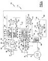
La
- un
carter 2 ; - une broche 4 porte-outil s'étendant suivant un axe vertical A ;
- un moteur d'entraînement 6, pneumatique dans l'exemple illustré ; et
- un
mécanisme 12 d'entraînement de la broche 4 reliant mécaniquement la broche 4 aumoteur 6.
- a
housing 2; - a tool-holder spindle 4 extending along a vertical axis A;
- a driving
motor 6, pneumatic in the illustrated example; and - a
mechanism 12 for driving the pin 4 mechanically connecting the pin 4 to themotor 6.
La broche 4 est reçue dans le carter 2 de manière mobile en rotation autour de son axe A et en translation le long de cet axe A. Le carter 2 est muni d'un système de lubrification 18.The spindle 4 is received in the
Afin de pouvoir assurer le perçage d'alésages, un outil de perçage sous forme d'un forêt est par exemple monté de manière amovible à l'extrémité inférieure 22 de la broche 4. Le système de lubrification 18 permet de lubrifier l'arête de l'outil pendant l'usinage.In order to be able to drill holes, a drilling tool in the form of a forest is for example removably mounted at the
L'arbre de sortie 24 du moteur 6 porte un pignon conique 26 de sortie qui engrène avec un pignon conique d'entrée 28 d'axe B, appartenant au mécanisme d'entraînement 12. Dans l'exemple représenté, le moteur 6 est disposé sensiblement à angle droit par rapport à la broche 4. Toutefois, il pourrait être sensiblement parallèle à cette dernière, comme exposé par exemple dans le document
Comme illustré par la
- un
premier pignon 32 engrenant avec le pignon d'entrée 28 ; - un
deuxième pignon 34 qui surmonte lepremier pignon 32 ; et - un embrayage 36 apte à accoupler le
deuxième pignon 34 sélectivement au pignon d'entrée 28 et aucarter 2.
- a
first pinion 32 meshing with theinput pinion 28; - a
second pinion 34 which overcomes thefirst pinion 32; and - a clutch 36 adapted to couple the
second gear 34 selectively to theinput gear 28 and thehousing 2.
Le premier pignon 32 est enfilé sur la broche 4 et est solidaire en rotation de cette dernière. La broche 4 est mobile en translation par rapport au pignon 32 le long de l'axe A. Cette liaison entre la broche 4 et le premier pignon 32 est par exemple obtenue grâce à des cannelures.The
Le deuxième pignon 34 comporte un filetage interne coopérant avec un filetage externe de la broche 4. Le deuxième pignon 34 est ainsi vissé, de manière connue, sur la broche 4. Le deuxième pignon 34 est guidé en rotation autour de son axe A par une cage à aiguilles 35 reçue dans le carter 2.The
Du fait de la liaison hélicoïdale entre la broche 4 et le deuxième pignon 34, le pignon 34 entraîne la broche 4 en translation le long de l'axe A en fonction de la vitesse relative de rotation entre le deuxième pignon 34 et la broche 4, c'est-à-dire en fonction de la vitesse relative de rotation entre le deuxième pignon 34 et le premier pignon 32.Due to the helical connection between the pin 4 and the
Dans le cas où l'entraînement en rotation de la broche 34 est effectué dans le sens horaire, le pas de la liaison hélicoïdale entre la broche 4 et le deuxième pignon 34 est, dans l'exemple illustré, à gauche. De cette manière, le mouvement d'avance de la broche 4, c'est-à-dire son déplacement en translation vers le bas le long de l'axe A (
Inversement, le mouvement de recul de la broche 4, c'est-à-dire son déplacement en rotation vers le haut le long de l'axe A (
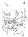
L'embrayage 36 comprend :
- un pignon rotatif d'embrayage 44 engrené avec le
deuxième pignon 34 ; - une pluralité de
premières clavettes 48, montées sur le pourtour du pignon rotatif d'embrayage 44, et mobiles par rapport aupignon 44 entre une position d'accouplement dupignon 44 avec le pignon d'entrée 28, et une position de libération dupignon 44; et - une pluralité de
deuxièmes clavettes 50, montées sur le pourtour du pignon rotatif d'embrayage 44, et mobiles par rapport aupignon 44 entre une position d'accouplement dupignon 44 avec lecarter 2, et une position de libération dupignon 44.
- a
rotary clutch gear 44 meshing with thesecond gear 34; - a plurality of
first keys 48, mounted on the periphery of the rotaryclutch gear 44, and movable relative to thepinion 44 between a coupling position of thepinion 44 with theinput pinion 28, and apinion release position 44; and - a plurality of
second keys 50, mounted on the periphery of the rotaryclutch gear 44, and movable relative to thepinion 44 between a coupling position of thepinion 44 with thecasing 2, and a release position of thepinion 44.
Le pignon rotatif d'embrayage 44 est d'axe B et rotatif pur autour de l'axe B par rapport au carter 2. Le pignon 44 est fixe en translation par rapport au carter 2. A cet effet, le pignon 44 est bloqué en translation par rapport au carter 2 et guidé en rotation pure autour de son axe B par deux roulements 51.The rotary
Dans la position d'accouplement des premières clavettes 48 (
Dans la position d'accouplement des deuxièmes clavettes 50 (
La configuration d'avance de l'embrayage 36 correspond donc à une configuration dans laquelle le deuxième pignon 32 est lié en rotation à l'arbre de sortie 24 du moteur 6, tandis que la configuration de recul de la broche 4 correspond à une configuration dans laquelle le deuxième pignon 34 est immobilisé en rotation par rapport au carter 2.The advance configuration of the clutch 36 therefore corresponds to a configuration in which the
Pour déplacer les clavettes 48 et 50, l'embrayage 36 comprend un poussoir 52 mobile entre une position d'avance dans laquelle le poussoir 52 maintient les premières clavettes 48 dans leur position d'accouplement et libère les deuxièmes clavettes 50, et une position de recul dans laquelle le poussoir 52 maintient les deuxièmes clavettes 50 dans leur position d'accouplement et libère les premières clavettes 48.To move the
Le poussoir 52 est reçu en translation à l'intérieur du pignon rotatif 44 le long de l'axe B, entre sa position d'avance et sa position de recul, et commandé par un vérin de déplacement 54.The
Le poussoir 52 est une tige comportant une portion élargie 56, et deux portions étroites 58 de part et d'autre de la portion élargie 56 suivant l'axe B. Le poussoir 52 forme ainsi, au niveau des jonctions entre la portion élargie 56 et les portions étroites 58 deux surfaces de came 60 et 62 (voir
Lors du déplacement du poussoir 52 jusqu'à sa position d'avance, la surface de came 60 déplace les premières clavettes 48 de leur position de libération (
Lors du déplacement du poussoir 52 jusqu'à sa position de recul (illustrée sur la
La surface de la portion élargie 56 maintient sélectivement les clavettes 48 et 50 dans leur position d'accouplement.The surface of the widened
Les clavettes 48 et 50 sont, dans l'exemple illustré, des billes disposées circonférentiellement autour du poussoir 52, en deux rangées respectives espacées le long de l'axe B.The
Chaque clavette 48, 50 est reçue dans un alésage radial respectif 66 (
Les clavettes 48 et 50 sont, dans l'exemple illlustré, espacées angulairement entre elles d'environ 90°.The
Chaque deuxième clavette 50 coopère, dans sa position d'accouplement, avec un évidement de blocage 68 (
De la même façon, chaque première clavette 48 coopère, dans sa position d'accouplement, avec un évidement de blocage en rotation 68 prévu dans une bague d'accouplement d'avance 74 (
Dans l'exemple illustré, le vérin de déplacement 54 (
Le piston 80 est sollicité élastiquement vers une position intermédiaire dans laquelle le poussoir 52 est entre sa position d'avance et sa position de recul. Dans cette position intermédiaire, les premières clavettes 48 et les deuxièmes clavettes 50 sont libérées.The
Le mécanisme d'entraînement 12 comprend en outre un mécanisme d'appui axial 84 (
Le piston 88 est mobile en translation dans un cylindre 91 (
Afin de limiter la course du mouvement de la broche 4 le long de l'axe A, la broche 4 comporte une butée de fin de course d'avance 96 et une butée de fin de course de recul 98.In order to limit the movement of the movement of the spindle 4 along the axis A, the spindle 4 comprises a forward limit stop 96 and a
La butée de fin de course d'avance 96 guide la broche 4 en rotation autour de l'axe A et en translation le long de l'axe A. La butée 96 est fixe en translation le long de l'axe A par rapport à la broche 4.The advance end stop 96 guides the spindle 4 in rotation about the axis A and in translation along the axis A. The
Lors de la fin de course d'avance de la broche 4, la butée 96 bloque la translation de la broche 4 le long de son axe A. Le deuxième pignon 34 se visse alors vers le haut (
Lorsque la broche 4 arrive en fin de course de recul, la butée 98 vient en appui contre une vanne pneumatique de détection de fin de course de recul 100.When the pin 4 arrives at the end of the backward stroke, the
Comme illustré sur les
- une source d'air sous pression 104 ;
- le vérin de déplacement 54 du poussoir 52 ;
le piston 88 détectant la fin de course d'avance de la broche 4 ;- la vanne de détection de fin de course de recul 100, commandée par contact avec la butée 98 ;
- une vanne de commande d'avance 106 pour amener le vérin 54 dans sa configuration d'avance ;
une vanne 108 de réduction du débit d'alimentation du moteur 6 ;- une vanne de commande de recul 109 pour amener le vérin 54 dans sa configuration de recul ; et
- une vanne d'alimentation 110 assurant l'alimentation de l'ensemble du dispositif de commande 102, commandée dans l'exemple illustré en ouverture par un bouton de mise en marche 114 et en fermeture par la vanne de détection de fin de course de recul 100, et apte à détecter une baisse de pression pour arrêter la machine 1.
- a source of
pressurized air 104; - the
displacement cylinder 54 of thepusher 52; - the
piston 88 detecting the advance end of the spindle 4; - the reversing end-of-
travel detection valve 100, controlled by contact with thestop 98; - a
control valve 106 to bring thecylinder 54 into its configuration in advance; - a
valve 108 for reducing the feed rate of theengine 6; - a
reverse control valve 109 for bringing thecylinder 54 into its recoil configuration; and - a
supply valve 110 providing power to theentire control device 102, controlled in the example shown in opening by astart button 114 and closed by the reversinglimit detection valve 100, and able to detect a pressure drop to stop the machine 1.
La vanne de détection de fin de course de recul 100 est par exemple un distributeur 3 voies, 2 positions. Une position est une position normale de fonctionnement, dans laquelle la vanne 100 est fermée et vers laquelle la vanne 100 est rappelée élastiquement, et l'autre position est une postion de commande de fermeture de la vanne d'alimentation 110 vers laquelle la vanne 100 est amenée par la butée de fin de course de recul 98.The reversing end-of-
La vanne de commande d'avance 106 est par exemple un distributeur 5 voies, 2 positions. Les deux positions sont une position de commande d'avance, dans laquelle la vanne 106 alimente la chambre d'avance 82, et une position inactive dans laquelle la vanne 106 est fermée. La vanne 106 est rappelée élastiquement vers sa position de commande d'avance. La vanne 106 est commandée pneumatiquement vers sa position inactive par le déplacement du piston 88 dans sa position de détection de fin de course d'avance.The
La vanne de réduction du débit d'alimentation 108 du moteur 6 est par exemple une vanne 3 voies, 2 positions. Une position est une position ouverte d'alimentation du moteur 6 et l'autre position est une position de réduction du débit d'alimentation. La vanne 108 est rappelée élastiquement vers sa position ouverte, et commandée pneumatiquement vers sa position de réduction de débit par le déplacement du piston 88 dans sa position de détection de fin de course d'avance.The feed
La vanne de commande de recul 109 est un distributeur 3 voies, 2 positions, dont une position est une position de commande de recul, dans laquelle la vanne 109 alimente la chambre de recul 83, et l'autre position est une position inactive dans laquelle la vanne 109 est fermée. La vanne 109 est rappelée élastiquement vers sa position inactive. La vanne 109 est commandée pneumatiquement vers sa position de commande de recul par le déplacement du piston 88 dans sa position de détection de fin de course d'avance.The
La vanne d'alimentation 110 est un distributeur 3 voies, 2 positions, dont une position de marche de la machine 1, et une position d'arrêt de la machine 1. La vanne 110 est rappelée élastiquement vers sa position d'arrêt. Elle est amenée dans sa position de marche par déplacement du bouton de mise en marche 114 et maintenue dans sa position de marche par un rétrocontrôle pneumatique de sécurité apte à détecter une baisse de pression et à permettre le déplacement de la vanne 110 dans sa position d'arrêt lors d'une chute de pression. La vanne 110 est en outre commandée pneumatiquement dans sa position d'arrêt par le passage de la vanne de détection de fin de course de recul 100 dans sa position de commande de fermeture.The
Le dispositif de commande 102 comprend un circuit pneumatique 114 reliant la source d'air 104, la vanne d'alimentation 110, le moteur 6, le vérin de déplacement 54, le piston 88, la vanne de détection de fin de course de recul 100, la vanne de commande d'avance 106, la vanne de réduction du débit d'alimentation 108 et la vanne de commande de recul 109.The
Le circuit pneumatique 114 comprend ainsi :
- un conduit d'alimentation 118 reliant un orifice de sortie 119 de la vanne d'alimentation 110
au moteur 6, la vanne de réduction de débit 108 obturant partiellement le conduit d'alimentation 118 dans sa position de réduction du débit d'alimentation du moteur 6; un conduit 120 piqué sur leconduit 118 entre les vannes 108et 110 et relié à l'orifice d'entrée 93 de la chambre de détection de fin decourse d'avance 92 délimitéepar le piston 88,la vanne 110 dans sa position de marche alimentant la chambre 92par le conduit 120 ;un conduit 123 piqué sur leconduit 118 entre les vannes 108et 110 et relié à un orifice de rétrocontrôle de sécurité 124 de la vanne 110 pour maintenir la vanne 110 dans sa position de marche si la pression en amont de la vanne 110 est supérieure à une valeur seuil;un conduit 125 piqué sur leconduit 120 entre la vanne 110 et l'orifice d'entrée 93 de la chambre 92, et relié à un orifice d'entrée 126 de la vanne de commande d'avance 106,la vanne 110 dans sa position de marche alimentant la vanne 106par le conduit 125 ;un conduit 127 reliant un orifice de sortie 128 de la vanne de commande d'avance 106 à la chambre d'avance 82 du vérin 54,la vanne 106 dans sa position de commande d'avance alimentant la chambre 82par le conduit 127;un conduit 140 reliant l'orifice de sortie 94 de la chambre 92 à un orifice d'entrée 141 de la vanne de commande de recul 109, de façon à alimenter la vanne 109 lorsque lepiston 88 est dans sa position de détection de fin de course d'avance ;un conduit 142 piqué sur leconduit 140 entre les orifices 94et 141, et relié àun orifice d'actionnement 143 de la vanne 109, de façon à amener la vanne de commande de recul 109 dans sa position de commande de recul lorsque lepiston 88 est dans sa position de détection de fin de course d'avance;un conduit 144 piqué sur leconduit 140 entre l'orifice de sortie 94 et le piquage duconduit 142,le conduit 144 étant relié àun orifice d'actionnement 145 de la vanne de commande d'avance 106, de façon à amener la vanne de commande d'avance 106 dans sa position inactive lorsque lepiston 88 est dans sa position de détection de fin de course d'avance, et avant d'amener la vanne de commande de recul 109 dans sa position de recul ;un conduit 146 piqué sur leconduit 140 entre le piquage duconduit 142 et l'orifice d'entrée 141 de la vanne 109,le conduit 146 étant relié àun orifice d'actionnement 147 de la vanne de réduction du débit 108, de façon à amener la vanne 108 dans sa position de réduction du débit d'alimentation du moteur 6 lorsque lepiston 88 est dans sa position de détection de fin de course d'avance, et avant d'alimenter la vanne de commande de recul 109 ;un conduit 150 piqué sur leconduit 140 et relié à un orifice d'entrée 151 de la vanne de détection de fin de course de recul 100, de façon à alimenter la vanne 100 lorsque lepiston 88 est dans sa position de détection, leconduit 150 étant, dans l'exemple illustré, piqué entre l'orifice de sortie 94 et le piquage duconduit 144 de la vanne de commande d'avance 106 ;un conduit 154 reliant un orifice de sortie 155 de la vanne de commande de recul 109 à la chambre de recul 83 du vérin 54, de façon à alimenter la chambre de recul 83 lorsque la vanne de recul 109 est dans sa position de recul ; etun conduit 160 reliant un orifice de sortie 161 de la vanne de détection de fin de course de recul 100 àun orifice d'actionnement 162 de la vanne d'alimentation 110, de façon à amener la vanne d'alimentation 110 dans sa position d'arrêt lorsque la vanne de détection de fin de course de recul 100 est dans sa position de commande de fermeture de la vanne 110.
- a
supply duct 118 connecting anoutlet orifice 119 of thesupply valve 110 to theengine 6, theflow reduction valve 108 partially closing thesupply duct 118 in its position of reducing the supply flow of theengine 6; - a
conduit 120 stitched on theconduit 118 between thevalves inlet port 93 of the advance end-of-travel detection chamber 92 delimited by thepiston 88, thevalve 110 in its position of astep supplying chamber 92 vialine 120; - a
conduit 123 stitched on theconduit 118 between thevalves safety feedback port 124 of thevalve 110 to maintain thevalve 110 in its operating position if the pressure upstream of thevalve 110 is greater than a threshold value; - a
duct 125 stitched on theduct 120 between thevalve 110 and theinlet orifice 93 of thechamber 92, and connected to aninlet port 126 of theadvance control valve 106, thevalve 110 in its position astep feeding valve 106 throughline 125; - a
conduit 127 connecting anoutlet port 128 of thefeed control valve 106 to thefeed chamber 82 of theram 54, thevalve 106 in its feed control position feeding thechamber 82 through theconduit 127; - a
duct 140 connecting theoutlet orifice 94 of thechamber 92 to aninlet port 141 of the reversingcontrol valve 109, so as to supply thevalve 109 when thepiston 88 is in its end-of-detection position race in advance; - a
conduit 142 stitched on theconduit 140 between theorifices actuating orifice 143 of thevalve 109, so as to bring therecoil control valve 109 into its recoil control position when thepiston 88 is in its advance end-of-travel detection position; - a
duct 144 stitched on theduct 140 between theoutlet orifice 94 and the tapping of theduct 142, theduct 144 being connected to anactuating orifice 145 of theadvance control valve 106, so as to bring the valveadvance control unit 106 in its inactive position when thepiston 88 is in its forward end-of-stroke detection position, and before bringing the reversingcontrol valve 109 into its retracted position; - a
conduit 146 stitched on theconduit 140 between the tapping of theconduit 142 and theinlet orifice 141 of thevalve 109, theconduit 146 being connected to anactuating orifice 147 of theflow reduction valve 108, so bringing thevalve 108 into its position of reducing the feed rate of theengine 6 when thepiston 88 is in its position of end-of-travel detection, and before supplying the reversingcontrol valve 109; - a
duct 150 stitched on theduct 140 and connected to aninlet port 151 of the reversing end-of-travel detection valve 100, so as to supply thevalve 100 when thepiston 88 is in its detection position, theduct 150 being, in the illustrated example, stitched between theoutlet orifice 94 and the tapping of theconduit 144 of theadvance control valve 106; - a
conduit 154 connecting anoutlet 155 of therecoil control valve 109 to therecoil chamber 83 of thecylinder 54, so as to supply therecoil chamber 83 when therecoil valve 109 is in its recoil position; and - a
duct 160 connecting anoutlet orifice 161 of the reversing end-of-travel detection valve 100 to anactuating orifice 162 of thesupply valve 110, so as to bring thesupply valve 110 into its position d stopping when the reversinglimit detection valve 100 is in its closed control position of thevalve 110.
Les étapes de commande de la machine 1 vont maintenant être décrites en référence aux
Le schéma de la
Dans la configuration de la
La source d'air 104 est alors reliée par le conduit 118 au moteur 6, en passant par la vanne de réduction de débit 108 dans sa position ouverte, de telle sorte que le moteur 6 est alimenté.The
Le piston 88 étant dans sa position d'obturation des orifices 93 et 94, l'air ne peut pas pénétrer dans la chambre 92 et ne peut pas sortir de la chambre 92, de telle sorte que les conduits en aval 140, 142, 144, 146, 150, 154 et 160 ne sont pas alimentés.The
En revanche, la vanne de commande d'avance 106 est dans sa position de commande d'avance et relie le conduit 125 au conduit 127 de telle sorte que la chambre d'avance 82 du vérin 54 est alimentée par la source d'air 104. Il s'ensuit que le vérin de déplacement 54 est amené dans sa configuration d'avance.On the other hand, the
L'embrayage 36 est alors dans sa configuration d'avance. Le moteur 6 entraîne le premier pignon 32 et le deuxième pignon 34, de telle sorte que la broche 4 avance en translation le long de son axe A.The clutch 36 is then in its configuration in advance. The
La
Dans la position de détection du piston 88, les orifices d'entrée 93 et de sortie 94 de la chambre 92 sont libérés, la chambre 92 est alimentée et les conduits en aval 140, 142, 144, 146, 150 sont alimentés.In the detection position of the
Le moteur 6 est toujours alimenté par la source d'air 104.The
L'orifice d'actionnement 145 de la vanne de commande d'avance 106 est alimenté par le conduit 144 et la vanne 106 est amenée dans sa position inactive. Dans sa position inactive, la vanne 106 n'alimente plus la chambre d'avance 82 du vérin 80 et le poussoir 52 vient dans sa position intermédiaire.The
Ensuite, l'orifice d'actionnement 143 de la vanne de commande de recul 109 est alimenté. La vanne 109 est alors amenée dans sa position de commande de recul.Then, the
Ensuite, l'orifice d'actionnement 147 de la vanne de réduction de débit 108 est alimenté. La vanne 108 est alors amenée dans sa position de réduction de débit.Then, the
Ensuite, l'orifice d'entrée 141 de la vanne de commande de recul 109 est alimenté. Dans la position de commande de recul de la vanne 109, le conduit 154 est alors alimenté et la vanne de commande de recul 109 alimente la chambre de recul 83 du vérin 54. Le poussoir 52 vient dans sa position de recul.Then, the
Lors du déplacement du piston 88 dans sa position de détection d'avance, l'air arrive dans le conduit 140.When the
Du fait de la longueur des conduits piqués 142, 144, 146 et de leur position respective de piquage sur le conduit 140, l'air arrive successivement à l'orifice d'actionnement 145, puis à l'orifice d'actionnement 143, puis à l'orifice d'actionnement 147, et enfin à l'orifice d'entrée 141.Due to the length of the stitched
Il s'ensuit que lors du déplacement du piston 88 dans sa position de détection de fin de course d'avance, la vanne de commande d'avance 106 est d'abord amenée dans sa position inactive.As a result, when the
La vanne de commande de recul 109 est ensuite ultérieurement amenée dans sa position de commande de recul.The
La vanne de réduction de débit 108 est ensuite ultérieurement amenée dans sa position d'obturation partielle du conduit d'alimentation 118 du moteur 6, de telle sorte que la vitesse de rotation du moteur 6 est réduite.The
La vanne de commande de recul 109 est ensuite ultérieurement alimentée.The
Le vérin de déplacement 54 est ensuite ultérieurement amené dans sa configuration de recul, et le poussoir 52 dans sa position de recul. L'embrayage 36 est alors dans sa configuration de recul.The
Le moteur 6 est toujours relié au premier pignon 32 et entraîne la broche 4 en rotation, mais n'est plus relié au deuxième pignon 34.The
Le deuxième pignon 34 est immobilisé en rotation autour de son axe B, et entraîne ainsi en translation la broche 4 le long de son axe A dans un mouvement de recul rapide.The
Lorsque la butée de fin de course de recul 98 arrive en contact avec la vanne de détection de fin de course de recul 100, la vanne 100 alimente le conduit d'actionnement 160 (
Le mécanisme d'embrayage 36 est robuste, et la machine 1 fiable.The clutch mechanism 36 is robust, and the machine 1 reliable.
En effet, les clavettes 48 et 50 sont déplaçables très rapidement par le poussoir 52 de telle sorte qu'elles ont une surface de prise importante avec les surfaces des évidements 68. En outre, les clavettes 48 et 50 sont rapportées sur le pignon 44 et de ce fait plus résistantes que, par exemple, des crabots dont les dents sont usinées.Indeed, the
L'immobilisation en translation du pignon rotatif d'embrayage 44 par rapport au carter 2 contribue également à la robustesse de l'embrayage 36. En effet, les vibrations du pignon rotatif 44 sont ainsi limitées. Cependant, une telle caractéristique peut être absente dans certaines variantes.The immobilization in translation of the rotary
En outre, l'embrayage 36 est simple. Il a un coût de fabrication relativement faible.In addition, the clutch 36 is simple. It has a relatively low manufacturing cost.
L'embrayage 36 a également un encombrement réduit. L'agencement du poussoir 52 à l'intérieur du pignon rotatif 44 contribue à la réduction de cet encombrement, tout comme le nombre limité des pièces d'embrayage. En effet, le mécanisme d'entraînement 12 ne comprend que quatre pignons 28, 32, 34, 44 et l'embrayage 36 est réalisé au moyen d'un seul pignon 44.The clutch 36 also has a small footprint. The arrangement of the
La réduction de vitesse du moteur 6 préalablement au recul de la broche 4 contribue à la fiabilité de la machine 1.The speed reduction of the
En effet, le mécanisme d'entraînement 12 et l'embrayage 36 sont ainsi moins sollicités lors du passage de l'embrayage 36 de sa configuration d'avance à sa configuration de recul.Indeed, the
Le dispositif de commande pneumatique 102 et le moteur pneumatique 6 présentent l'avantage par rapport à un dispositif électrique d'un encombrement et d'un poids réduit. Néanmoins, en variante, le moteur 6, le dispositif de commande 102, le vérin de déplacement 54 du poussoir 52, les unités de détection de fin de course d'avance et de recul de la broche 4 peuvent être individuellement ou même tous des organes électriques.The
Le dispositif de commande électrique comprend alors une unité de pilotage comprenant une mémoire dans laquelle sont stockés des programmes de pilotage du moteur d'entraînement adaptés pour assurer une réduction de vitesse du moteur 6 avant recul de la broche 4.The electrical control device then comprises a control unit comprising a memory in which are stored drive motor control programs adapted to ensure a speed reduction of the
En variante, l'embrayage 36 ne possède qu'une seule première clavette 48 et/ou une seule deuxième clavette 50.In a variant, the clutch 36 has only one
Claims (15)
- Machining tool (1) comprising:- a housing (2);- a tool holder spindle (4) which extends along an axis (A);- a driving motor (6) for the tool holder spindle; and- a driving mechanism (12) for the tool holder spindle (4) connecting the driving motor (6) mechanically to the tool holder spindle (4), the driving mechanism (12) comprising:the driving mechanism (12) comprising an engagement means (36) having a configuration for withdrawing the spindle (4) in which the second driving member (34) and the driving motor (6) are disengaged, and a configuration for advancing the spindle (4) in which the second driving member (34) and the driving motor (6) are engaged, the engagement means (36) comprising a rotational member for engagement (44) connected in rotation to the second driving member (34), the rotational member for engagement (44) being moveable rotationally about an axis (B) relative to the housing (2);- a first member (32) for driving the spindle (4) rotationally about the axis (A) thereof relative to the the housing (2); and- a second member (34) for driving the spindle (4) translationally along the axis (A) thereof relative to the housing (2), the second driving member (34) being screwed on a threaded section (40) of the spindle (4) so that the spindle (4) advances or withdraws along the axis (A) thereof as a function of the relative speed of rotation between the first member (32) and the second member (34);
characterised in that the engagement means (36) comprises furthermore:- at least one first dog (48) which is moveable relative to the rotational member for engagement (44) between a position coupling the rotational member (44) to the driving motor (6) and a position freeing the rotational member (44); and- at least one second dog (50) which is moveable relative to the rotational member for engagement (44) between a position coupling the rotational member (44) to the housing (2) and a position freeing the rotational member (44),- the first dog (48) being in its coupled position and the second dog (50) being in its free position when the engagement means (36) is in its configuration for advancing the spindle (4), the first dog (48) being in its free position and the second dog (50) being in its coupled position when the engagement means (36) is in its configuration for withdrawing the spindle (4). - Machining tool (1) according to claim 1, in which the first dog (48) and/or the second dog (50) is integral in rotation with the rotational member for engagement (44).
- Machining tool (1) according to claim 1 or 2, in which the first dog (48) and/or the second dog (50) is radially moveable relative to the axis of rotation (B) of the rotational member for engagement (44) between its coupled position and its free position.
- Machining tool (1) according to any of the preceding claims, in which the rotational member for engagement (44) is mounted fixed in translation relative to the housing (2) along the axis (B) thereof.
- Machining tool (1) according to any of the preceding claims, in which the second driving member (34) is a pinion, the rotational member for engagement (44) being a pinion meshing with the second driving member (34), the driving mechanism (12) comprising an input pinion (28) meshing with an output pinion (26) of the driving motor (6), the rotational member for engagement (44) being coupled to the input pinion (28) when the engagement means (36) is in its advancing position.
- Machining tool (1) according to claim 5, in which the first driving member (32) is a pinion meshing with the input pinion (28).
- Machining tool (1) according to any of the preceding claims, in which the engagement means (36) comprises a tappet (52) which is moveable between an advancing position in which the tappet (52) retains the first dog (48) in its coupled position and frees the second dog (50) and a withdrawing position in which the tappet (52) retains the second dog (50) in its coupled position and frees the first dog (48).
- Machining tool (1) according to any of the preceding claims, in which the first dog (48) and/or the second dog (50) is a ball received in a boring (66) of the rotational member for engagement (44).
- Machining tool (1) according to any of the preceding claims, comprising a device (102) for controlling the driving motor (6) and the engagement means (36).
- Machining tool according to claim 9, in which the control device (102) comprises a unit for detecting the end of the advancing course of the spindle (4), the control device (102) guiding the engagement means (36) into its withdrawing configuration upon detecting the end of the advancing course of the spindle (4).
- Machining tool (1) according to claim 10, in which the control device (102) causes a reduction in the speed of rotation of the driving motor (6) upon detecting the end of the advancing course of the spindle (4).
- Machining tool (1) according to any of the claims 9 to 11, in which the driving motor (6) is pneumatic, the control device (102) being pneumatic and comprising a pneumatic valve (108) for reducing the supply quantity to the driving motor (6).
- Machining tool (1) according to claim 12, in which the control device (102) comprises a pneumatic control circuit (114) for the valve for reducing the quantity (108) and for the displacement thrustor (54), the circuit (114) supplying the valve (108) for reducing the quantity upstream of the displacement thrustor (54) such that the control device (102) ensures a reduction in the supply quantity to the driving motor (6) before causing the displacement of the tappet (52) to its withdrawing position.
- Method for machining, characterised in that it is implemented by means of a machining tool (1) according to any of the preceding claims.
- Method according to claim 14, comprising a step of advancing the spindle (4) in which the speed of rotation of the spindle (4) is ≥ 6,000 rpm, preferably ≥ 8,000, more preferably ≥ 10,000 rpm, more preferably ≥ 12,000 rpm, more preferably ≥ 14,000 rpm, more preferably ≥ 15,000 rpm.
Applications Claiming Priority (1)
| Application Number | Priority Date | Filing Date | Title |
|---|---|---|---|
| FR0851982A FR2929157B1 (en) | 2008-03-27 | 2008-03-27 | MECHANICAL ADVANCED MACHINING MACHINE AND METHOD OF MACHINING |
Publications (2)
| Publication Number | Publication Date |
|---|---|
| EP2105249A1 EP2105249A1 (en) | 2009-09-30 |
| EP2105249B1 true EP2105249B1 (en) | 2011-04-27 |
Family
ID=39712309
Family Applications (1)
| Application Number | Title | Priority Date | Filing Date |
|---|---|---|---|
| EP09155921A Expired - Fee Related EP2105249B1 (en) | 2008-03-27 | 2009-03-23 | Machining tool with automatic feed and machining method |
Country Status (4)
| Country | Link |
|---|---|
| US (1) | US8469640B2 (en) |
| EP (1) | EP2105249B1 (en) |
| DE (1) | DE602009001127D1 (en) |
| FR (1) | FR2929157B1 (en) |
Cited By (2)
| Publication number | Priority date | Publication date | Assignee | Title |
|---|---|---|---|---|
| CN104959642A (en) * | 2015-06-11 | 2015-10-07 | 苏州市吴中区胥口广博模具加工厂 | Pneumatic drill handpiece of automatic double-station rotary table type drilling machine |
| US11602795B2 (en) | 2020-01-08 | 2023-03-14 | Stanley Black & Decker, Inc. | Railroad track rail drill |
Families Citing this family (15)
| Publication number | Priority date | Publication date | Assignee | Title |
|---|---|---|---|---|
| FR2873315B1 (en) * | 2004-07-23 | 2007-12-14 | Recoules Sa Sa | MECHANICAL ADVANCED MACHINING MACHINE AUTHORIZING AN UNFINISHING OPERATION |
| FR2907695B1 (en) * | 2006-10-27 | 2009-06-26 | Cooper Power Tools Sas Soc Par | METHOD FOR DRILLING A BORING AND CORRESPONDING MACHINE |
| FR2929157B1 (en) | 2008-03-27 | 2010-04-23 | Cooper Power Tools Sas | MECHANICAL ADVANCED MACHINING MACHINE AND METHOD OF MACHINING |
| FR2935915B1 (en) * | 2008-09-18 | 2010-10-08 | Cooper Power Tools Sas | MACHINING MACHINE AND ASSOCIATED MACHINING METHOD |
| US20100111626A1 (en) * | 2008-10-31 | 2010-05-06 | Cooper Industries | Cushion mechanism for a positive peck feed drill |
| SE534892C2 (en) * | 2009-09-25 | 2012-02-07 | Atlas Copco Tools Ab | Compressed air driven ADE machine |
| DE102010000970C5 (en) * | 2010-01-18 | 2022-10-13 | Suspa Gmbh | Height-adjustable actuation device |
| DE102012108378A1 (en) * | 2012-09-07 | 2014-03-13 | Indubrand Ag | Method for producing a high-precision bore |
| CN103223511B (en) * | 2013-05-19 | 2015-01-21 | 交通运输部北海救助局 | Cutter head feeding and retraction transmission control mechanism of emergency rescue fast anti-explosion tapping equipment |
| CN103551902B (en) * | 2013-08-23 | 2015-12-02 | 福鼎市金雄机车部件有限公司 | Motor is utilized automatically to control the device of slide unit rectilinear motion and accurate stop position |
| US10583538B2 (en) * | 2015-11-16 | 2020-03-10 | Apex Brands, Inc. | Feed oscillation via variable pitch gears |
| KR101780154B1 (en) * | 2016-07-27 | 2017-09-20 | 대모 엔지니어링 주식회사 | Hydraulic percussion device and construction equipment having the same |
| US10033388B1 (en) | 2017-03-21 | 2018-07-24 | Xilinx, Inc. | Circuit for and method of enabling the selection of a circuit |
| US9966908B1 (en) | 2017-06-02 | 2018-05-08 | Xilinx, Inc. | Circuit for and method of implementing a differential input receiver |
| FR3117053B1 (en) * | 2020-12-07 | 2023-07-21 | Seti Tec | drilling device with spindle uncoupling and braking means |
Family Cites Families (47)
| Publication number | Priority date | Publication date | Assignee | Title |
|---|---|---|---|---|
| US2453136A (en) * | 1943-04-26 | 1948-11-09 | Ex Cell O Corp | Chip breaking drill chuck |
| US3003372A (en) | 1959-09-29 | 1961-10-10 | Howard J Findley | Apparatus for cutting material |
| US3487729A (en) * | 1967-12-06 | 1970-01-06 | Zephyr Mfg Co | Positive depth control drill |
| US3583822A (en) * | 1968-10-31 | 1971-06-08 | Rockwell Mfg Co | Portable power tool |
| US3574290A (en) * | 1968-12-16 | 1971-04-13 | Dresser Ind | Tool actuating device |
| DE1958412A1 (en) | 1969-11-21 | 1971-05-27 | Rockwell Mfg Co | Portable power tool |
| US3679320A (en) * | 1970-10-28 | 1972-07-25 | Zephyr Mfg Co | Portable right angle drill |
| US3767313A (en) * | 1971-10-20 | 1973-10-23 | Zephyr Mfg Co | Positive feed drill |
| US3838934A (en) * | 1973-03-02 | 1974-10-01 | R Petroff | Machine tool |
| AT323506B (en) | 1973-09-11 | 1975-07-10 | Voest Ag | DEVICE FOR DEEP HOLE DRILLING OF METALLIC WORKPIECES |
| US4111590A (en) * | 1976-10-07 | 1978-09-05 | Robert E. Eash | Positive feed drill |
| US4083646A (en) * | 1976-12-09 | 1978-04-11 | Zephyr Manufacturing Co., Inc. | Positive feed drill with rapid advance |
| US4097177A (en) * | 1977-03-11 | 1978-06-27 | Close Ross A | Power head drilling and turning unit |
| US4123188A (en) | 1977-04-04 | 1978-10-31 | Gardner-Denver Company | Control system for peck drilling tool |
| US4198180A (en) * | 1978-05-11 | 1980-04-15 | Mcdonnell Douglas Corporation | Thrust controlled drilling apparatus |
| US4443139A (en) * | 1982-03-18 | 1984-04-17 | In-Tex Tool Corporation | Positive feed drill |
| US4681490A (en) * | 1983-10-31 | 1987-07-21 | Dresser Industries, Inc. | Retraction apparatus for automatic feed drills or the like |
| US4592681A (en) * | 1983-10-31 | 1986-06-03 | Dresser Industries, Inc. | Retraction apparatus for automatic feed drills or the like |
| US4591299A (en) * | 1984-05-21 | 1986-05-27 | Dresser Industries, Inc. | Rapid feed apparatus for automatic feed drills or the like |
| US4612998A (en) * | 1984-07-12 | 1986-09-23 | P. V. Tool, Inc. | Retracting positive feed drill with idle mode |
| US4688970A (en) * | 1985-08-09 | 1987-08-25 | Dresser Industries, Inc. | Power drill and automatic control system therefore |
| US4648756A (en) * | 1985-12-13 | 1987-03-10 | Allen-Bradley Company, Inc. | Two speed automatic shift drill |
| GB8620690D0 (en) * | 1986-08-27 | 1986-10-08 | Desoutter Ltd | Positive feed device |
| US4799833A (en) * | 1987-12-14 | 1989-01-24 | Dresser Industries, Inc. | Clutch for positive feed drill |
| US4854786A (en) * | 1988-05-26 | 1989-08-08 | Allen-Bradley Company, Inc. | Computer controlled automatic shift drill |
| US4822215A (en) * | 1988-05-26 | 1989-04-18 | Allen-Bradley Company, Inc. | Thrust and torque sensitive drill |
| US5149232A (en) * | 1989-06-30 | 1992-09-22 | Dresser Industries, Inc. | Mechanical peck drill |
| US5073068A (en) | 1990-05-24 | 1991-12-17 | Doler Inc. | Peck feed drilling machine |
| US5022798A (en) * | 1990-06-11 | 1991-06-11 | Dresser Industries, Inc. | Thrust-responsive two-speed drill and method of operation |
| US5022800A (en) * | 1990-07-09 | 1991-06-11 | P.V. Tool, Inc. | Rapid advance feed drill with idle mode |
| US5351797A (en) * | 1990-10-01 | 1994-10-04 | Cooper Industries, Inc. | Retraction system for a power tool drive spindle |
| US5054968A (en) * | 1990-10-18 | 1991-10-08 | Dresser Industries, Inc. | Mechanical positive feed drill with supported spindle |
| US5143161A (en) * | 1991-09-20 | 1992-09-01 | P.V. Tool, Inc. | Right angle positive feed tapper |
| US6193447B1 (en) * | 1999-06-18 | 2001-02-27 | Cooper Technologies Company | Positive feed tool having a retract valve |
| US6196772B1 (en) * | 1999-06-18 | 2001-03-06 | Cooper Technologies Company | Positive feed tool having a clutch |
| US6261033B1 (en) | 1999-06-18 | 2001-07-17 | Cooper Technologies Company | Positive feed tool having rectractable members |
| US6371701B1 (en) | 2000-03-07 | 2002-04-16 | The Boeing Company | Apparatus having a controllable dwell and associated method |
| FR2829952B1 (en) | 2001-09-25 | 2004-01-23 | Recoules | MACHINING MACHINE WITH STANDARDIZED DRIVE MECHANISM |
| DE10308089A1 (en) | 2003-02-24 | 2004-09-02 | Airbus Deutschland Gmbh | Drilling assistance device for aiding in the use of a hand held power drill, has alignment, suction and depth setting units combined in a single device that is attached to a drill |
| ITUD20030260A1 (en) | 2003-12-30 | 2005-06-30 | Marika Serafin | FORMING DEVICE FOR CONCRETE JETS. |
| FR2873315B1 (en) * | 2004-07-23 | 2007-12-14 | Recoules Sa Sa | MECHANICAL ADVANCED MACHINING MACHINE AUTHORIZING AN UNFINISHING OPERATION |
| US7048077B2 (en) * | 2004-09-26 | 2006-05-23 | P.V. Tool, Inc. | Drilling machine with pneumatic control |
| US7510024B2 (en) | 2004-09-26 | 2009-03-31 | Pv Tools, Inc. | System and method for breaking chips formed by a drilling operation |
| ITPD20050322A1 (en) | 2005-10-28 | 2007-04-29 | Lg Technologies Srl | DEVICE FOR HIGH-SPEED PLATE DRILLING FOR PRINTERS AND SIMILAR CIRCUITS |
| FR2907695B1 (en) * | 2006-10-27 | 2009-06-26 | Cooper Power Tools Sas Soc Par | METHOD FOR DRILLING A BORING AND CORRESPONDING MACHINE |
| FR2915121B1 (en) * | 2007-04-17 | 2009-10-09 | Cooper Power Tools Sas Soc Par | MACHINING MACHINE. |
| FR2929157B1 (en) | 2008-03-27 | 2010-04-23 | Cooper Power Tools Sas | MECHANICAL ADVANCED MACHINING MACHINE AND METHOD OF MACHINING |
-
2008
- 2008-03-27 FR FR0851982A patent/FR2929157B1/en not_active Expired - Fee Related
-
2009
- 2009-03-23 DE DE602009001127T patent/DE602009001127D1/en active Active
- 2009-03-23 EP EP09155921A patent/EP2105249B1/en not_active Expired - Fee Related
- 2009-03-26 US US12/412,054 patent/US8469640B2/en not_active Expired - Fee Related
Cited By (2)
| Publication number | Priority date | Publication date | Assignee | Title |
|---|---|---|---|---|
| CN104959642A (en) * | 2015-06-11 | 2015-10-07 | 苏州市吴中区胥口广博模具加工厂 | Pneumatic drill handpiece of automatic double-station rotary table type drilling machine |
| US11602795B2 (en) | 2020-01-08 | 2023-03-14 | Stanley Black & Decker, Inc. | Railroad track rail drill |
Also Published As
| Publication number | Publication date |
|---|---|
| FR2929157B1 (en) | 2010-04-23 |
| DE602009001127D1 (en) | 2011-06-09 |
| US8469640B2 (en) | 2013-06-25 |
| EP2105249A1 (en) | 2009-09-30 |
| FR2929157A1 (en) | 2009-10-02 |
| US20090245955A1 (en) | 2009-10-01 |
Similar Documents
| Publication | Publication Date | Title |
|---|---|---|
| EP2105249B1 (en) | Machining tool with automatic feed and machining method | |
| EP1618978B1 (en) | Machine tool with mechanical advance allowing a jam clearing of chips | |
| EP1916045B1 (en) | Device for drilling a bore | |
| FR2918592A1 (en) | Rotating tool-carrying spindle displacing device for e.g. automatic industrial drilling machine, has inner screw thread connected in driving relationship with engine units to rotate sleeve along same direction similar to that of spindle | |
| CA2857719C (en) | Machining process | |
| CA2780783C (en) | Axial machining device | |
| EP1317329B1 (en) | Boring head | |
| EP2498938B1 (en) | Tapping unit with protection means | |
| EP0346231B1 (en) | Drill, especially for a programmable machine | |
| EP3209458B1 (en) | Improved vibratory machining device | |
| EP3003616B1 (en) | Vibratory machining apparatus | |
| EP1238737B1 (en) | Tapping unit | |
| FR2546091A1 (en) | INTERCHANGEABLE TOOL SUPPORT UNIT FOR MACHINE | |
| WO2016199047A1 (en) | Lathe and guide bush | |
| FR3065179B1 (en) | EFFECTOR DEVICE FOR ORBITAL DRILLING, FOR MOUNTING ON A ROBOT ARM OR ON AN AUTOMATIC PORTABLE UNIT | |
| EP3666432B1 (en) | Device for securing a boring device to a boring grate comprising an expandable ball hub | |
| FR2823142A1 (en) | Method for changing circular saw blade comprises removing blade to be sharpened from changing head and at same time attaching second sharpened tool to clamping flange and to a second clamping flange placed on changing head | |
| EP1295676B1 (en) | Pneumatic tool with automatic shut-off at the end of a machining cycle | |
| FR2497701A1 (en) | Cut bar feed for lathe - uses step-wise revolving barrel to align successive axial tubes with output tube also serving as shears | |
| CA3165276A1 (en) | Electrospindle with integrated feed with automatic tool holder change | |
| FR2743743A1 (en) | HAND INSTRUMENT FOR MACHINING PARTS, PARTICULARLY MECHANICAL PARTS | |
| CH568815A5 (en) | ||
| FR3033510A1 (en) | TRANSMISSION DEVICE ADAPTED TO TRANSFORM A ROTATION MOVEMENT OF A MOTOR SHAFT OF A MACHINE SUCH AS A DRILL INTO A ROTATION MOVEMENT AND TRANSLATION OF A CHUCK | |
| FR3036988A1 (en) | ABRASIVE TOOL FOR BORING | |
| BE522066A (en) |
Legal Events
| Date | Code | Title | Description |
|---|---|---|---|
| PUAI | Public reference made under article 153(3) epc to a published international application that has entered the european phase |
Free format text: ORIGINAL CODE: 0009012 |
|
| AK | Designated contracting states |
Kind code of ref document: A1 Designated state(s): AT BE BG CH CY CZ DE DK EE ES FI FR GB GR HR HU IE IS IT LI LT LU LV MC MK MT NL NO PL PT RO SE SI SK TR |
|
| AX | Request for extension of the european patent |
Extension state: AL BA RS |
|
| 17P | Request for examination filed |
Effective date: 20100309 |
|
| AKX | Designation fees paid |
Designated state(s): DE ES FR GB IT |
|
| GRAP | Despatch of communication of intention to grant a patent |
Free format text: ORIGINAL CODE: EPIDOSNIGR1 |
|
| GRAS | Grant fee paid |
Free format text: ORIGINAL CODE: EPIDOSNIGR3 |
|
| GRAA | (expected) grant |
Free format text: ORIGINAL CODE: 0009210 |
|
| AK | Designated contracting states |
Kind code of ref document: B1 Designated state(s): DE ES FR GB IT |
|
| REG | Reference to a national code |
Ref country code: GB Ref legal event code: FG4D Free format text: NOT ENGLISH |
|
| REF | Corresponds to: |
Ref document number: 602009001127 Country of ref document: DE Date of ref document: 20110609 Kind code of ref document: P |
|
| REG | Reference to a national code |
Ref country code: DE Ref legal event code: R096 Ref document number: 602009001127 Country of ref document: DE Effective date: 20110609 |
|
| PG25 | Lapsed in a contracting state [announced via postgrant information from national office to epo] |
Ref country code: ES Free format text: LAPSE BECAUSE OF FAILURE TO SUBMIT A TRANSLATION OF THE DESCRIPTION OR TO PAY THE FEE WITHIN THE PRESCRIBED TIME-LIMIT Effective date: 20110807 |
|
| PLBE | No opposition filed within time limit |
Free format text: ORIGINAL CODE: 0009261 |
|
| STAA | Information on the status of an ep patent application or granted ep patent |
Free format text: STATUS: NO OPPOSITION FILED WITHIN TIME LIMIT |
|
| 26N | No opposition filed |
Effective date: 20120130 |
|
| REG | Reference to a national code |
Ref country code: DE Ref legal event code: R097 Ref document number: 602009001127 Country of ref document: DE Effective date: 20120130 |
|
| PG25 | Lapsed in a contracting state [announced via postgrant information from national office to epo] |
Ref country code: IT Free format text: LAPSE BECAUSE OF FAILURE TO SUBMIT A TRANSLATION OF THE DESCRIPTION OR TO PAY THE FEE WITHIN THE PRESCRIBED TIME-LIMIT Effective date: 20110427 |
|
| REG | Reference to a national code |
Ref country code: FR Ref legal event code: PLFP Year of fee payment: 8 |
|
| REG | Reference to a national code |
Ref country code: GB Ref legal event code: 732E Free format text: REGISTERED BETWEEN 20160503 AND 20160504 |
|
| REG | Reference to a national code |
Ref country code: FR Ref legal event code: TP Owner name: APEX BRANDS, INC., US Effective date: 20160609 |
|
| REG | Reference to a national code |
Ref country code: DE Ref legal event code: R081 Ref document number: 602009001127 Country of ref document: DE Owner name: APEX BRANDS, INC., WILMINGTON, US Free format text: FORMER OWNER: COOPER POWER TOOLS SAS, OZOIR LA FERRIERE, FR |
|
| REG | Reference to a national code |
Ref country code: FR Ref legal event code: PLFP Year of fee payment: 9 |
|
| REG | Reference to a national code |
Ref country code: FR Ref legal event code: PLFP Year of fee payment: 10 |
|
| PGFP | Annual fee paid to national office [announced via postgrant information from national office to epo] |
Ref country code: DE Payment date: 20200327 Year of fee payment: 12 |
|
| PGFP | Annual fee paid to national office [announced via postgrant information from national office to epo] |
Ref country code: FR Payment date: 20200325 Year of fee payment: 12 |
|
| REG | Reference to a national code |
Ref country code: DE Ref legal event code: R119 Ref document number: 602009001127 Country of ref document: DE |
|
| PGFP | Annual fee paid to national office [announced via postgrant information from national office to epo] |
Ref country code: GB Payment date: 20210920 Year of fee payment: 13 |
|
| PG25 | Lapsed in a contracting state [announced via postgrant information from national office to epo] |
Ref country code: FR Free format text: LAPSE BECAUSE OF NON-PAYMENT OF DUE FEES Effective date: 20210331 Ref country code: DE Free format text: LAPSE BECAUSE OF NON-PAYMENT OF DUE FEES Effective date: 20211001 |
|
| GBPC | Gb: european patent ceased through non-payment of renewal fee |
Effective date: 20220323 |
|
| PG25 | Lapsed in a contracting state [announced via postgrant information from national office to epo] |
Ref country code: GB Free format text: LAPSE BECAUSE OF NON-PAYMENT OF DUE FEES Effective date: 20220323 |