EP3666332A1 - Dispositif de traitement de tissu - Google Patents
Dispositif de traitement de tissu Download PDFInfo
- Publication number
- EP3666332A1 EP3666332A1 EP18211779.6A EP18211779A EP3666332A1 EP 3666332 A1 EP3666332 A1 EP 3666332A1 EP 18211779 A EP18211779 A EP 18211779A EP 3666332 A1 EP3666332 A1 EP 3666332A1
- Authority
- EP
- European Patent Office
- Prior art keywords
- tissue
- wavelength
- light
- protein
- photoconversion
- Prior art date
- Legal status (The legal status is an assumption and is not a legal conclusion. Google has not performed a legal analysis and makes no representation as to the accuracy of the status listed.)
- Withdrawn
Links
Images


Classifications
-
- A—HUMAN NECESSITIES
- A61—MEDICAL OR VETERINARY SCIENCE; HYGIENE
- A61N—ELECTROTHERAPY; MAGNETOTHERAPY; RADIATION THERAPY; ULTRASOUND THERAPY
- A61N5/00—Radiation therapy
- A61N5/06—Radiation therapy using light
- A61N5/0613—Apparatus adapted for a specific treatment
- A61N5/062—Photodynamic therapy, i.e. excitation of an agent
-
- A—HUMAN NECESSITIES
- A61—MEDICAL OR VETERINARY SCIENCE; HYGIENE
- A61N—ELECTROTHERAPY; MAGNETOTHERAPY; RADIATION THERAPY; ULTRASOUND THERAPY
- A61N5/00—Radiation therapy
- A61N5/06—Radiation therapy using light
- A61N5/0613—Apparatus adapted for a specific treatment
- A61N5/0622—Optical stimulation for exciting neural tissue
-
- A—HUMAN NECESSITIES
- A61—MEDICAL OR VETERINARY SCIENCE; HYGIENE
- A61N—ELECTROTHERAPY; MAGNETOTHERAPY; RADIATION THERAPY; ULTRASOUND THERAPY
- A61N5/00—Radiation therapy
- A61N5/06—Radiation therapy using light
- A61N2005/0626—Monitoring, verifying, controlling systems and methods
- A61N2005/0629—Sequential activation of light sources
-
- A—HUMAN NECESSITIES
- A61—MEDICAL OR VETERINARY SCIENCE; HYGIENE
- A61N—ELECTROTHERAPY; MAGNETOTHERAPY; RADIATION THERAPY; ULTRASOUND THERAPY
- A61N5/00—Radiation therapy
- A61N5/06—Radiation therapy using light
- A61N2005/063—Radiation therapy using light comprising light transmitting means, e.g. optical fibres
-
- A—HUMAN NECESSITIES
- A61—MEDICAL OR VETERINARY SCIENCE; HYGIENE
- A61N—ELECTROTHERAPY; MAGNETOTHERAPY; RADIATION THERAPY; ULTRASOUND THERAPY
- A61N5/00—Radiation therapy
- A61N5/06—Radiation therapy using light
- A61N2005/065—Light sources therefor
- A61N2005/0651—Diodes
-
- A—HUMAN NECESSITIES
- A61—MEDICAL OR VETERINARY SCIENCE; HYGIENE
- A61N—ELECTROTHERAPY; MAGNETOTHERAPY; RADIATION THERAPY; ULTRASOUND THERAPY
- A61N5/00—Radiation therapy
- A61N5/06—Radiation therapy using light
- A61N2005/0658—Radiation therapy using light characterised by the wavelength of light used
- A61N2005/0662—Visible light
-
- A—HUMAN NECESSITIES
- A61—MEDICAL OR VETERINARY SCIENCE; HYGIENE
- A61N—ELECTROTHERAPY; MAGNETOTHERAPY; RADIATION THERAPY; ULTRASOUND THERAPY
- A61N5/00—Radiation therapy
- A61N5/06—Radiation therapy using light
- A61N2005/0664—Details
- A61N2005/0667—Filters
Definitions
- the disclosure relates to a device and system for treating tissue and a method for treating tissue.
- Light therapy has been used in the treatment of tissue for many years.
- LLLT low-level laser therapy
- PBMT photobiomodulation therapy
- These techniques apply low-level (or low-power) lasers or light emitting diodes (LEDs) to tissue in order to treat the tissue.
- LEDs light emitting diodes
- the techniques have been found to provide a wide range of benefits, such as improving tissue repair, reducing pain and/or inflammation, treating cutaneous disorders, and so on.
- the techniques rely on the low-level of light applied to the tissue inducing photochemical and photobiological reactions in the tissue and it is these reactions that provide these benefits.
- opsins are present in various types of tissue, including the skin, hair follicles, blood vessels, brain, fat, etc. When stimulated by light, the proteins have been seen to provide useful medical benefits. For example, different types of opsins stimulated by ultraviolet (UV) light have been shown to participate in the production of a melanin pigment, improve vasorelaxation and/or vasodilation, maintain the hair growth phase, improve fat metabolism, aid in the differentiation of epidermal keratinocytes, and so on.
- UV ultraviolet
- a device for treating tissue comprising a light source configured to emit light to illuminate tissue.
- the light source is configured to alternate between emitting light of a first wavelength to stimulate at least partial photoconversion of a protein in at least part of the tissue and emitting light of a second wavelength to at least partially reverse the at least partial photoconversion of the protein in the at least part of the tissue.
- the first wavelength and the second wavelength are different.
- the light source may be configured to alternate between emitting the light of the first wavelength to stimulate partial photoconversion of the protein in at least part of the tissue and emitting the light of the second wavelength to at least partially reverse the partial photoconversion of the protein in the at least part of the tissue.
- the light source may be configured to emit the light of the first wavelength for a predefined time period to stimulate partial photoconversion of the protein in at least part of the tissue. In some embodiments, the light source may be configured to emit the light of the first wavelength at a predefined intensity to stimulate partial photoconversion of the protein in at least part of the tissue.
- the light source may be configured to alternate between emitting the light of the first wavelength to stimulate photoconversion of the protein in a first part of the tissue and emitting the light of the second wavelength to at least partially reverse the photoconversion of the protein in the first part of the tissue.
- the light source may be configured to emit the light of the first wavelength to illuminate the first part of the tissue to stimulate photoconversion of the protein in the first part of the tissue and emit the light of the second wavelength to illuminate a second part of the tissue to at least partially reverse the photoconversion of the protein in the first part of the tissue.
- the light source may comprise a first light source configured to emit the light of the first wavelength to illuminate the first part of the tissue and a second light source configured to emit the light of the second wavelength to illuminate the second part of the tissue.
- the light source may comprise a filter configured to pass the light of the first wavelength to illuminate the first part of the tissue and pass the light of the second wavelength to illuminate the second part of the tissue.
- the light source may be configured to alternate between (a) emitting the light of the first wavelength to stimulate photoconversion of the protein in a first part of the tissue and emitting the light of the second wavelength to at least partially reverse the photoconversion of the protein in the first part of the tissue and (b) emitting the light of the first wavelength to stimulate photoconversion of the protein in a second part of the tissue and emitting the light of the second wavelength to at least partially reverse the photoconversion of the protein in the second part of the tissue.
- the light source may be configured to emit the light of the first wavelength to illuminate the first part of the tissue to stimulate photoconversion of the protein in the first part of the tissue and emit the light of the second wavelength to illuminate the second part of the tissue to at least partially reverse the photoconversion of the protein in the first part of the tissue.
- the light source may be configured to emit the light of the first wavelength to illuminate the second part of the tissue to stimulate photoconversion of the protein in the second part of the tissue and emit the light of the second wavelength to illuminate the first part of the tissue to at least partially reverse the photoconversion of the protein in the second part of the tissue.
- the device may comprise a lens configured to focus the light of the first wavelength at a first predefined depth in the tissue and/or focus the light of the second wavelength at a second predefined depth in the tissue.
- the second predefined depth may be the same as the first predefined depth or different to the first predefined depth.
- a system comprising the device as claimed in any of the preceding claims and a processor.
- the processor may be configured to acquire an indication of a photoconversion state of the protein and control the light source to alternate between emitting the light of the first wavelength and the light of the second wavelength according to the photoconversion state of the protein.
- a method for treating tissue comprises alternating between emitting light of a first wavelength to stimulate at least partial photoconversion of a protein in at least part of the tissue and emitting light of a second wavelength to at least partially reverse the at least partial photoconversion of the protein in the at least part of the tissue.
- the first wavelength and the second wavelength are different.
- a computer program product comprising a computer readable medium.
- the computer readable medium has computer readable code embodied therein.
- the computer readable code is configured such that, on execution by a suitable computer or processor, the computer or processor is caused to perform the method described earlier.
- the limitations of existing techniques are addressed.
- the light source in addition to the light source being configured to emit light of a first wavelength to stimulate at least partial photoconversion of a protein in at least part of the tissue, the light source is also configured to emit light of second wavelength that is different to the first wavelength.
- the emission of the light of the second wavelength at least partially reverses the at least partial photoconversion of the protein in the at least part of the tissue. In this way, the proteins can be brought back to (or close to) their original state.
- the light source is configured to alternate between emitting the light of the first wavelength and the light of the second wavelength, which means that the protein can be repeatedly brought into (or close to) a stable photoproduct and back to (or close to) their original state. This means that desensitization of the protein can be reversed, which enables continued or further therapeutic benefits to be provided.
- the device described herein can be a wearable device (e.g. a wearable patch). That is, in some embodiments, the device may be configured to be worn by a subject for treating tissue of the subject according to some embodiments.
- the device described herein may be a handheld device. That is, in some embodiments, the device may be configured to be held by a user (e.g. the subject or another user) for treating tissue of the subject according to some embodiments.
- the device described herein can be an insertable or implantable device. That is, in some embodiments, the device may be configured to be inserted into the tissue (or the subject) or implanted into the tissue (or the subject) for treating tissue of the subject.
- the device described herein may be configured to be placed on a surface in the environment of the subject (e.g. on top of a table or bed), for treating tissue of the subject.
- the tissue referred to herein may comprise any type of tissue.
- the tissue may comprise epithelial tissue such as the skin (e.g. the epidermis of the skin, the cells of the skin, hair follicles, or similar) or the lining of hollow organs (e.g. the lining of gastrointestinal tract organs or any other hollow organs), muscle tissue (e.g. cardiac muscle tissue, skeletal muscle, or any other muscle tissue), connective tissue (e.g. fat, bone, tendons, or any other connective tissue), nervous tissue (e.g. the brain, spinal cord, nerves, or any other nervous tissue), blood vessels, or any other tissue, or any combination of tissue.
- epithelial tissue such as the skin (e.g. the epidermis of the skin, the cells of the skin, hair follicles, or similar) or the lining of hollow organs (e.g. the lining of gastrointestinal tract organs or any other hollow organs), muscle tissue (e.g. cardiac muscle tissue, skeletal muscle, or any
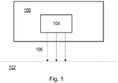
- Fig. 1 illustrates a device 100 for treating tissue 102 according to an embodiment.
- the device 100 comprises a light source 104 configured to emit light to illuminate the tissue 102.
- the light source 104 is configured to alternate between emitting light of a first wavelength to stimulate at least partial photoconversion of a protein in at least part of the tissue 102 and emitting light of a second wavelength to at least partially reverse the at least partial photoconversion of the protein in the at least part of the tissue 102.
- the first wavelength and the second wavelength are different.
- the first wavelength and the second wavelength referred to herein can be wavelengths in a range from 300 to 1000 nm.
- the first wavelength referred to herein may be a wavelength in a range from 325 to 555 nm.
- the first wavelength referred to herein may be a wavelength in a range from 400 to 555 nm, for example a wavelength in a range from 410 to 510 nm.
- the first wavelength referred to herein may be a wavelength in a range from 325 to 425 nm, for example a wavelength in a range from 350 to 410 nm.
- the second wavelength referred to herein may be a wavelength in a range from 470 to 600 nm, for example a wavelength in a range from 510 to 560 nm.
- the second wavelength may be a wavelength that is longer than the peak absorption (maximum absorption) wavelength of the photoconverted protein.
- the photoconverted protein may also be referred to herein as a photoproduct protein. A person skilled in the art will be able to identify first and second wavelengths for any given photoconvertable protein.
- the light source 104 referred to herein can be any type of light source.
- the light source 104 may, for example, comprise one or more coherent light sources and/or one or more incoherent light sources.
- An example of a coherent light source includes, but is not limited to, a laser.
- Examples of incoherent light sources include, but are not limited to, a light emitting diodes (LED) and an organic light emitting diode (OLED).
- the light source may comprise any one or more of these light sources and/or any other type of light source.
- the light source may also comprise any combination of light sources.
- the light source 104 may comprise a single light source or a plurality of light sources, e.g. an array of light sources.
- the protein in at least part of the tissue 102 is a photoconvertable protein. That is, a protein that undergoes photoconversion from a native (or dark) state to a photoproduct protein.
- the protein referred to herein can be any photoconvertable protein, such as an opsin, or any other photoconvertable protein, e.g. containing G-protein Coupled Receptors (GPCRs).
- GPCRs G-protein Coupled Receptors
- the photoconversion of the protein may be a conformational conversion of the protein. That is, the absorption of light by the protein in its native (or dark) state may change a conformation of the protein. This change in conformation may, for example, initiate physiological reactions in the tissue 102. The change in conformation converts the protein into the photoproduct protein.
- the photoproduct protein may be a stable photoproduct. That is, the photoproduct protein may be resistant to change when exposed to light.
- the absorption properties of the photoproduct protein can be different to those of the original photoconvertable protein, e.g. the absorption properties of the photoproduct protein may be shifted towards longer wavelengths and/or may have a higher absorption value compared to the original photoconvertable protein. This is illustrated in Figs. 2 , 3 and 4 .
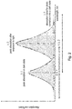
- Fig. 2 is an illustration of absorption spectra for a photoconvertable protein. More specifically, Fig. 2 is an illustration of an absorption coefficient of a photoconvertable protein as a function of a wavelength of light.
- ⁇ 1 corresponds to the wavelength at which a peak absorption (maximum absorption) occurs in the protein when in its native (or dark) state, i.e. prior to photoconversion to a photoproduct protein.
- ⁇ 2 corresponds to the wavelength at which a peak absorption (maximum absorption) occurs in the protein after the protein has been exposed to light, i.e. once the protein has been photoconverted into a photoproduct protein.
- ⁇ 3 corresponds to the wavelength selected for at least partially reversing the photoconversion of the protein in the at least part of the tissue 102, i.e. for at least partially photoconverting the photoproduct protein back into the native (or dark) state of the photoconvertable protein. That is, ⁇ 3 corresponds to the second wavelength referred to herein.
- ⁇ 1 and ⁇ 2 may be closer to each other.
- the absorption spectra and the peak absorption (maximum absorption) of the native (or dark) state photoconvertable proteins and their photoproduct proteins may overlap.
- An example of such a photoconvertable protein is illustrated in Fig. 3 .
- Fig. 3 is an illustration of absorption spectra for a photoconvertable protein. More specifically, Fig. 3 is an illustration of absorbance of a photoconvertable protein as a function of a wavelength of light.
- the photoconvertable protein is a human opsin called encephalopsin or panopsin, which can also be referred to as opsin-3 or OPN3.
- OPN3 is present in various tissues, such as in the brain, eyes, liver, inner root sheath of the hair follicles epidermis, dermal fibroblasts, and human epidermal melanocytes.
- the full width half maximum (FWHM) of this peak is approximately 40 nm.
- the full width half maximum (FWHM) of this peak is approximately 50 nm.
- OPN3 absorbs blue light and thus, when exposed to blue light, OPN3 photoconverts into a photoproduct protein.
- the blue-absorbing photoproduct of OPN3 (with its maximum absorption at 470 nm) is stable in the absence of light and reverts back into its native (or dark) blue-absorbing state by the subsequent illumination with orange light (long-pass filter, 50% cut off at 560 nm).
- a wavelength of 560 nm or above is equivalent to ⁇ 3 of Fig. 2 . That is, a wavelength of 560 nm or above corresponds to the second wavelength referred to herein, which is selected for at least partially reversing the photoconversion of OPN3 in the at least part of the tissue 102.
- Fig. 4 is an illustration of absorption spectra for a photoconvertable protein. More specifically, Fig. 4 is an illustration of absorbance of a photoconvertable protein as a function of a wavelength of light.
- the photoconvertable protein is a human opsin called neuropsin, which can also be referred to as opsin-5 or OPN5.
- OPN5 is present in various tissues, such as in the testis, epididymis, epidermis basal layer, human epidermal melanocytes, and epidermal keratinocytes.
- the full width half maximum (FWHM) of this peak is approximately 20 nm.
- the full width half maximum (FWHM) of this peak is approximately 50 nm.
- OPN5 absorbs UV light and thus, when exposed to UV light, OPN5 photoconverts into a photoproduct protein.
- a wavelength of 520 nm or above is equivalent to ⁇ 3 of Fig. 2 . That is, a wavelength of 520 nm or above corresponds to the second wavelength referred to herein, which is selected for at least partially reversing the photoconversion of OPN5 in the at least part of the tissue 102.
- OPN3 and OPN5 A summary of the spectral properties of OPN3 and OPN5 is provided in the following table: Protein (opsin) Maximum absorption (dark state) FWHM (dark state) Maximum absorption (photo-product state) FWHM (photo-product state) Wavelength to reverse photoconversion OPN3 460 nm +/- 50 nm 470 nm +/- 50 nm Orange O56 glass cutoff longpass filter with 50% T at 560 nm OPN5 380 nm +/- 30 nm 470 nm +/- 40 nm >480 nm; e.g. 520 nm
- the first wavelength may be a wavelength in a range from 325 to 555 nm, for example a wavelength in a range from 400 to 555 nm, for example a wavelength in a range from 410 to 510 nm.
- the first wavelength may be a wavelength in a range from 325 to 425 nm, for example a wavelength in a range from 350 to 410 nm.
- the second wavelength may be a wavelength in a range from 470 to 600 nm, for example a wavelength in a range from 510 to 560 nm.
- OPN3 and OPN5 have been described as examples, it will be understood that other opsins (such as those outside of visual tissue, e.g. OPN2, OPN1, OPN4) and other photoconvertable proteins will exhibit a similar behavior. That is, other opsins will also behave as photoconvertable proteins in the manner described herein. The disclosure thus applies to any photoconvertable protein.
- the light source 104 of the device 100 described herein is configured to alternate between emitting light of a first wavelength to stimulate at least partial photoconversion of a protein in at least part of the tissue 102 and emitting light of a second wavelength to at least partially reverse the at least partial photoconversion of the protein in the at least part of the tissue 102.
- the light source 104 of the device 100 can be configured to alternate between emitting light of the first wavelength and emitting light of the second wavelength in various ways. Some of these ways will now be described with reference to Figs. 5-7 .
- the light source 104 of the device 100 may be configured to alternate between emitting light of the first wavelength 106-1 to stimulate partial photoconversion of the protein in the at least part of the tissue 102 and emitting light of the second wavelength 106-2 to at least partially reverse the partial photoconversion of the protein in the at least part of the tissue 102.
- the light source 104 of the device 100 may be configured to emit the light of the first wavelength 106-1 and the light of the second wavelength to illuminate the same part of the tissue 102 or different part of the tissue.
- the light source 104 of the device 100 in these embodiments is configured to emit light of the first wavelength 106-1 to stimulate only partial photoconversion of the protein in at least part of the tissue 102, the photoconversion of the protein never actually completes.
- Fig. 5 is a simplified schematic illustration of light 106 emitted by the device 100 described earlier to illuminate tissue 102 according to such an embodiment.
- the light source 104 of the device 100 is configured to emit the light of the first wavelength 106-1 for a predefined time period to stimulate partial photoconversion of the protein in the at least part of the tissue 102.
- the predefined time period may be referred to as a pulse duration.
- the pulse duration can be defined according to a pulsing frequency and may, for example, be defined based on one or more biological processes, such as any one or more of the protein photoconversion itself, calcium ion dynamics, and dynamics of ion channels (where the latter two participate in transduction of the light initiated by photoconvertable proteins).
- a pulsing frequency that can be used include, but are not limited to 1000Hz (e.g. for a pulse duration in the milliseconds range), 1 Hz (e.g. for a pulse duration in the seconds range), or 0.01 Hz (e.g. for a pulse duration in the minutes range).
- the light source 104 of the device 100 may be configured to cease emitting the light of the first wavelength 106-1 upon expiry of the predefined time period. In this way, the light source 104 of the device 100 can be configured to cease emitting the light of the first wavelength 106-1 before the photoconversion of the protein completes.
- the predefined time period can be defined based on the time taken for complete photoconversion of the protein to occur. In particular, the predefined time period can be set to be shorter than the time taken for complete photoconversion of the protein to occur.
- the light source 104 of the device 100 may be configured to emit the light of the second wavelength 106-2 before, on, or after expiry of the predefined time period.
- the light source 104 of the device 100 may be configured to emit light of the first wavelength 106-1 at a first time T1 and to emit light of the second wavelength 106-2 at a second time T2.
- the first time T1 and the second time T2 are different.
- the light source 104 of the device 100 may be configured to emit light of the first wavelength 106-1 and to emit light of the second wavelength 106-2 consecutively or sequentially.
- the light source 104 of the device 100 may be configured to pulse the emission of the light of the first wavelength 106-1 and the light of the second wavelength 106-2, e.g. according to the predefined time period (or pulse duration).
- the light source 104 of the device 100 may be configured to emit the light of the first wavelength 106-1 at a predefined intensity to stimulate partial photoconversion of the protein in the at least part of the tissue 102.
- the predefined intensity may be set so as to only stimulate partial photoconversion of the protein in the at least part of the tissue 102.
- the light source 104 of the device 100 may be configured to emit the light of the first wavelength 106-1 at an intensity that does not allow complete photoconversion of the protein.
- the predefined intensity can be an intensity in a range from 1 to 200 mW/cm 2 or an intensity up to 500 mW/cm 2 . In some embodiments, the predefined intensity may be set based on the predefined time period mentioned earlier, or vice versa.
- the light dosage provided to the at least part of the tissue 102 by the light source 104 of the device 100 can be restricted (e.g. by limiting the time for which and/or the intensity with which the light source 104 is configured to emit the light of the first wavelength 106-1) to avoid complete photoconversion of the protein in the at least part of the tissue 102.
- the light dosage provided to the at least part of the tissue 102 by the light source 104 of the device 100 may be in a range from 1J/cm 2 to 100 J/cm 2 .
- the embodiments where the light source 104 of the device 100 is configured to emit light of the first wavelength 106-1 to stimulate only partial photoconversion of the protein in the at least part of the tissue 102, such that the photoconversion of the protein never actually completes can be advantageous.
- proteins for which complete photoconversion occurs mask off proteins in deeper layers of the tissue.
- due to the limited depth in the tissue to which light can penetrate there will be faster protein conversion closer to the skin surface.
- the treatment may be restricted to superficial layers of tissue and it may not be possible for the treatment to penetrate to deeper layers that are masked. It can also be difficult to reverse complete photoconversion.
- the masking that may otherwise hinder the treatment of deeper layers of tissue can be avoided or the effect of masking can at least be reduced and a more effective treatment is then possible.
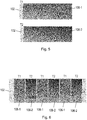
- Fig. 6 is a simplified schematic illustration of light 106 emitted by the device 100 described earlier to illuminate tissue 102 according to another embodiment.
- the light source 104 of the device 100 is configured to alternate between emitting the light of the first wavelength 106-1 to stimulate photoconversion of the protein in a first part of the tissue 102 and emitting the light of the second wavelength 106-2 to at least partially reverse the photoconversion of the protein in the first part of the tissue 102.
- complete photoconversion of the protein is allowed, which can provide treatment advantages.
- the light source 104 may be configured to emit the light of the first wavelength 106-1 to illuminate the first part of the tissue 102 to stimulate photoconversion of the protein in the first part of the tissue 102 and emit the light of the second wavelength 106-2 to illuminate a second part of the tissue 102 to at least partially reverse the photoconversion of the protein in the first part of the tissue 102.
- the first part of the tissue 102 and the second part of the tissue 102 can be different.
- the first part of the tissue 102 may be one half of the tissue and the second part of the tissue 102 may be the other half of the tissue 102.
- the first part of the tissue 102 may be adjacent to (e.g.
- a patterned illumination can be provided by illuminating different parts of the tissue 102 with light of different wavelengths.
- the illumination may be in the form of a chess board.
- the emission of the light of the first wavelength 106-1 to illuminate the first part of the tissue 102 may at least partially stimulate photoconversion of the protein in the second part of the tissue 102 due to the light of the first wavelength 106-1 being scattered by the tissue 102 into the second part of the tissue 102.
- the emission of the light of the second wavelength 106-2 to illuminate the second part of the tissue 102 may at least partially reverse the photoconversion of the protein in the first part of the tissue 102 due to the light of the second wavelength 106-2 being scattered by the tissue 102 into the first part of the tissue 102.
- the light source 104 of the device 100 may be configured to emit light of the first wavelength 106-1 at a first time T1 and to emit light of the second wavelength 106-2 at a second time T2.
- the first time T1 and the second time T2 can be different.
- the light source 104 of the device 100 may be configured to emit light of the first wavelength 106-1 and to emit light of the second wavelength 106-2 sequentially. In this way, a sequential illumination can be provided. In some embodiments, a patterned and sequential illumination can be provided.
- the patterned illumination means that only part of the tissue 102 is illuminated with the light of the first wavelength 106-1, such that photoconversion only occurs in that part of the tissue 102 and not in other parts of the tissue 102. That is, a proportion of the tissue is free from photoconversion. In particular, the proteins in the non-illuminated parts of the tissue 102 are not photoconverted. In this way, complete photoconversion can be allowed in some parts of the tissue 102, while the effect of masking is reduced since photoconversion does not occur at all in other parts of the tissue 102.
- the light source 104 of the device 100 may comprise a first light source configured to emit the light of the first wavelength 106-1 to illuminate the first part of the tissue 102 and a second light source configured to emit the light of the second wavelength 106-2 to illuminate the second part of the tissue 102.
- the first light source and the second light source may be different light sources. In this way, an array type illumination light source is provided.
- different light sources may be configured to emit light to illuminate different parts of the tissue 102.
- the light source 104 of the device 100 may comprise a filter.
- the filter can be configured to pass the light of the first wavelength 106-1 to illuminate the first part of the tissue 102 and pass the light of the second wavelength 106-2 to illuminate the second part of the tissue 102.
- the filter may comprise an illumination mask.
- the filter may comprise one or more color filters.
- the light source 104 of the device 100 may be a continuous light source.
- Fig. 7 is a simplified schematic illustration of light 106 emitted by the device 100 described earlier to illuminate tissue 102 according to an embodiment.
- the light source 104 of the device 100 is configured to alternate between (a) emitting the light of the first wavelength to stimulate photoconversion of the protein in a first part of the tissue and emitting the light of the second wavelength to at least partially reverse the photoconversion of the protein in the first part of the tissue and (b) emitting the light of the first wavelength to stimulate photoconversion of the protein in a second part of the tissue and emitting the light of the second wavelength to at least partially reverse the photoconversion of the protein in the second part of the tissue.
- the light source 104 of the device 100 may be configured to emit the light of the first wavelength 106-1 to stimulate photoconversion of the protein in a first part of the tissue 102 and emit the light of the second wavelength 106-2 to at least partially reverse the photoconversion of the protein in the first part of the tissue 102 at a first time T1.
- the light source 104 of the device 100 may also configured to emit the light of the first wavelength 106-1 to stimulate photoconversion of the protein in a second part of the tissue 102 and the light of the second wavelength 106-2 to at least partially reverse the photoconversion of the protein in the second part of the tissue 102 at a second time T2.
- the first time T1 and the second time T2 can be different.
- the light source 104 of the device 100 can be configured to emit the light of the first wavelength 106-1 to illuminate the first part of the tissue 102 to stimulate photoconversion of the protein in the first part of the tissue 102 and emit the light of the second wavelength 106-2 to illuminate the second part of the tissue 102 to at least partially reverse the photoconversion of the protein in the first part of the tissue 102.
- the light source 104 of the device 100 can be configured to emit the light of the first wavelength 106-1 to illuminate the second part of the tissue 102 to stimulate photoconversion of the protein in the second part of the tissue 102 and emit the light of the second wavelength 106-2 to illuminate the first part of the tissue 102 to at least partially reverse the photoconversion of the protein in the second part of the tissue 102.
- the device 100 may comprises a lens.
- the lens can be configured to focus the light of the first wavelength 106-1 at a first predefined depth in the tissue 102.
- the lens can be configured to focus the light of the second wavelength 106-2 at a second predefined depth in the tissue.
- the second predefined depth may be the same as the first predefined depth or different to the first predefined depth.
- the second predefined depth may be greater than or less than the first predefined depth.
- the second wavelength may be greater than or less than the first wavelength.
- the first wavelength 106-1 may be less than the second wavelength 106-2 and the first predefined depth in the tissue 102 may be less than the second predefined depth in the tissue 102.
- the light of the longer second wavelength 106-2 may be focused deeper in the tissue 102 than the light of the shorter first wavelength 106-1.
- the first wavelength 106-1 may be less than the second wavelength 106-2 and the first predefined depth in the tissue 102 may be greater than the second predefined depth in the tissue 102.
- the light of the shorter first wavelength 106-1 may be focused deeper than the light of the longer second wavelength 106-2.
- the first wavelength 106-1 may be greater than the second wavelength 106-2 and the first predefined depth in the tissue 102 may be less than the second predefined depth in the tissue 102.
- the light of the shorter second wavelength 106-2 may be focused deeper in the tissue 102 than the light of the longer first wavelength 106-1.
- the first wavelength 106-1 may be the greater than the second wavelength 106-2 and the first predefined depth in the tissue 102 may be greater than the second predefined depth in the tissue 102.
- the light of the longer first wavelength 106-1 may be focused deeper than the light of the shorter second wavelength 106-2.
- the lens may comprise a single lens or a plurality (e.g. an array) of lenses.
- a single lens may have a chromatic aberration or an inverse chromatic aberration.
- a plurality of lenses (such as an array of lenses) may have a chromatic aberration and/or an inverse chromatic aberration.
- Figs. 8(a), (b) and (c) are simplified schematic illustrations of example lenses according to an embodiment.
- Fig. 8(a) is a simplified schematic illustration of a refractive lens
- Fig. 8(b) is a simplified schematic illustration of a phase Fresnel (PF) lens
- Fig. 8(c) is a simplified schematic illustration of a combined refractive and PF lens.
- the light source 104 of the device 100 is configured to emit white light through the example lenses. The light of blue wavelength, green wavelength, and red wavelength is shown following the emission of the white light through the example lenses.
- the refractive lens illustrated in Fig. 8(a) has a chromatic aberration.
- the refractive lens is configured to focus longer wavelengths at greater depths than shorter wavelengths. That is, for the refractive lens, the longer the wavelength of light, the further the focal point is from the lens. For example, the red light is focused further away from the lens than the blue light and the green light, and the green light is focused further away from the lens than the blue light.
- the PF lens illustrated in Fig. 8(b) has an inverse chromatic aberration. As such, as illustrated in Fig. 8(b) , the PF lens is configured to focus shorter wavelengths at greater depths than longer wavelengths.
- the combination of the refractive lens with the PF lens provides a mutual cancellation.
- the inverse chromatic aberration of the PF lens compensates for the chromatic aberration of the refractive lens.
- a single lens with a chromatic aberration or an inverse chromatic aberration in an axial direction or a plurality of lenses (such as an array of lenses) with a chromatic aberration and/or an inverse chromatic aberration in an axial direction can be used to allow a deeper or shallower focusing of the first and second wavelengths 106-1, 106-2.
- the system may also comprise a processor.
- the processor can be implemented in numerous ways, with software and/or hardware, to perform the various functions described herein.
- the processor can comprise a plurality of software and/or hardware modules, each configured to perform, or that are for performing, individual or multiple steps of the method described herein.
- the processor may comprise one or more processors (such as one or more microprocessors, one or more multi-core processors and/or one or more digital signal processors (DSPs)), one or more processing units, and/or one or more controllers (such as one or more microcontrollers) that may be configured or programmed (e.g.
- the processor may be implemented as a combination of dedicated hardware (e.g. amplifiers, pre-amplifiers, analog-to-digital convertors (ADCs) and/or digital-to-analog convertors (DACs)) to perform some functions and a processor (e.g. one or more programmed microprocessors, DSPs and associated circuitry) to perform other functions.
- dedicated hardware e.g. amplifiers, pre-amplifiers, analog-to-digital convertors (ADCs) and/or digital-to-analog convertors (DACs)
- ADCs analog-to-digital convertors
- DACs digital-to-analog convertors
- the processor can be configured to acquire an indication of a photoconversion state of the protein. In some embodiments, the processor can be configured to acquire the indication of the photoconversion state of the protein using optical spectroscopy. A person skilled in the art will be aware of various optical spectroscopy techniques and the manner in which the photoconversion state of the protein can be determined using these techniques. In some embodiments, the photoconversion state of the protein may be a ratio of the amount of protein to the amount of photoproduct protein.
- the processor can also be configured to control the light source 104 of the device 100 to alternate between emitting the light of the first wavelength and the light of the second wavelength according to (or depending on) the photoconversion state of the protein. In this way, the effectiveness of the treatment can be further improved.
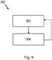
- Fig. 9 is a flow chart illustrating a method 900 for treating tissue 102 according to an embodiment. More specifically, the method 900 of Fig. 9 is a method of operating the device 100 described earlier. The method 900 may generally be performed by or under the control of a processor, such as that described earlier.
- the method then proceeds again to block 902 of Fig. 9 . That is, the method 900 of Fig. 9 comprises alternating between emitting the light of the first wavelength (block 902 of Fig. 9 ) and emitting light of the second wavelength (block 904 of Fig. 9 ).
- the method 900 of Fig. 9 comprises operating the light source 104 of the device 100 described earlier to alternate between emitting the light of the first wavelength and emitting light of the second wavelength.
- a processor (such as that described earlier) may be configured to operate (e.g. control) the light source to alternate between emitting the light of the first wavelength and emitting light of the second wavelength. At least one or all of the steps of the method can be automated according to some embodiments.
- the computer readable medium has computer readable code embodied therein.
- the computer readable code is configured such that, on execution by a suitable computer or processor, the computer or processor is caused to perform the method described herein.
- the computer readable medium may be, for example, any entity or device capable of carrying the computer program product.
- the computer readable medium may include a data storage, such as a ROM (such as a CD-ROM or a semiconductor ROM) or a magnetic recording medium (such as a hard disk).
- the computer readable medium may be a transmissible carrier, such as an electric or optical signal, which may be conveyed via electric or optical cable or by radio or other means.
- the computer readable medium may be constituted by such a cable or other device or means.
- the computer readable medium may be an integrated circuit in which the computer program product is embedded, the integrated circuit being adapted to perform, or used in the performance of, the method described herein.
- a device 100, a system, a method 900 and a computer program product that address the limitations associated with the existing techniques. Therefore, there is provided an improved device and system for treating tissue and an improved method for treating tissue.
- the device, system and method can be useful for reducing inflammation, improving blood flow, treating brain conditions related to blood flow, treating neurodegenerative diseases, treating inflammatory skin diseases, healing wounds, treating pigmentation disorders (e.g. vitiligo), improving anti-ageing, reducing blood pressure, improving hair growth, and similar.
- the device, system and method can be used to reduce collagen in tissue due to the anti-proliferative and anti-inflammatory action of the light.
- the device, system and method can also be useful in preventing the formation of granulation tissue around an implanted device so that the implanted device is not deformed due to collagen contraction during the implantation period and/or in facilitating the extraction as less collagen is formed around the implant.
- a computer program may be stored or distributed on a suitable medium, such as an optical storage medium or a solid-state medium supplied together with or as part of other hardware, but may also be distributed in other forms, such as via the Internet or other wired or wireless telecommunication systems. Any reference signs in the claims should not be construed as limiting the scope.
Landscapes
- Health & Medical Sciences (AREA)
- Biomedical Technology (AREA)
- Engineering & Computer Science (AREA)
- Life Sciences & Earth Sciences (AREA)
- Nuclear Medicine, Radiotherapy & Molecular Imaging (AREA)
- Pathology (AREA)
- Biophysics (AREA)
- Radiology & Medical Imaging (AREA)
- Animal Behavior & Ethology (AREA)
- General Health & Medical Sciences (AREA)
- Public Health (AREA)
- Veterinary Medicine (AREA)
- Neurosurgery (AREA)
- Radiation-Therapy Devices (AREA)
Priority Applications (1)
| Application Number | Priority Date | Filing Date | Title |
|---|---|---|---|
| EP18211779.6A EP3666332A1 (fr) | 2018-12-11 | 2018-12-11 | Dispositif de traitement de tissu |
Applications Claiming Priority (1)
| Application Number | Priority Date | Filing Date | Title |
|---|---|---|---|
| EP18211779.6A EP3666332A1 (fr) | 2018-12-11 | 2018-12-11 | Dispositif de traitement de tissu |
Publications (1)
| Publication Number | Publication Date |
|---|---|
| EP3666332A1 true EP3666332A1 (fr) | 2020-06-17 |
Family
ID=64664938
Family Applications (1)
| Application Number | Title | Priority Date | Filing Date |
|---|---|---|---|
| EP18211779.6A Withdrawn EP3666332A1 (fr) | 2018-12-11 | 2018-12-11 | Dispositif de traitement de tissu |
Country Status (1)
| Country | Link |
|---|---|
| EP (1) | EP3666332A1 (fr) |
Citations (6)
| Publication number | Priority date | Publication date | Assignee | Title |
|---|---|---|---|---|
| WO2010056970A2 (fr) * | 2008-11-14 | 2010-05-20 | The Board Of Trustees Of The Leland Stanford Junior University | Stimulation optique de cellules cibles et modifications de celles-ci |
| US20110125077A1 (en) | 2009-11-25 | 2011-05-26 | Medtronic, Inc. | Optical stimulation therapy |
| WO2013163681A1 (fr) * | 2012-05-01 | 2013-11-07 | University Of Western Sydney | Protéines fluorescentes et leurs utilisations |
| US20160030765A1 (en) * | 2014-07-29 | 2016-02-04 | Circuit Therapeutics, Inc. | System and method for optogenetic therapy |
| US20160045599A1 (en) * | 2013-04-29 | 2016-02-18 | The Board Of Trustees Of Theleland Stanford Junior University | Devices, systems and methods for optogenetic modulation of action potentials in target cells |
| US20170157269A1 (en) * | 2010-11-05 | 2017-06-08 | The Board Of Trustees Of The Leland Stanford Junior University | Optogenetic control of reward-related behaviors |
-
2018
- 2018-12-11 EP EP18211779.6A patent/EP3666332A1/fr not_active Withdrawn
Patent Citations (6)
| Publication number | Priority date | Publication date | Assignee | Title |
|---|---|---|---|---|
| WO2010056970A2 (fr) * | 2008-11-14 | 2010-05-20 | The Board Of Trustees Of The Leland Stanford Junior University | Stimulation optique de cellules cibles et modifications de celles-ci |
| US20110125077A1 (en) | 2009-11-25 | 2011-05-26 | Medtronic, Inc. | Optical stimulation therapy |
| US20170157269A1 (en) * | 2010-11-05 | 2017-06-08 | The Board Of Trustees Of The Leland Stanford Junior University | Optogenetic control of reward-related behaviors |
| WO2013163681A1 (fr) * | 2012-05-01 | 2013-11-07 | University Of Western Sydney | Protéines fluorescentes et leurs utilisations |
| US20160045599A1 (en) * | 2013-04-29 | 2016-02-18 | The Board Of Trustees Of Theleland Stanford Junior University | Devices, systems and methods for optogenetic modulation of action potentials in target cells |
| US20160030765A1 (en) * | 2014-07-29 | 2016-02-04 | Circuit Therapeutics, Inc. | System and method for optogenetic therapy |
Similar Documents
| Publication | Publication Date | Title |
|---|---|---|
| KR101862280B1 (ko) | 안면 부위별 설정된 파장대의 광 조사가 가능한 엘이디 마스크 장치 | |
| JP6714606B2 (ja) | 脳の非侵襲的神経刺激療法のための方法、システム及び装置 | |
| Desmet et al. | Clinical and experimental applications of NIR-LED photobiomodulation | |
| Gavish et al. | Therapeutic efficacy of home-use photobiomodulation devices: a systematic literature review | |
| CA2640203C (fr) | Phototherapie de faible intensite de traitement de troubles retinien, maculaire et des voies optiques | |
| US8435273B2 (en) | High powered light emitting diode photobiology device | |
| US7331964B2 (en) | Laser therapy device for animals and methods of using the same and manufacturing the same | |
| US20090005839A1 (en) | Skin Tanning System Incorporating Skin Rejuvenating Light | |
| Merigo et al. | Efficacy of LLLT in swelling and pain control after the extraction of lower impacted third molars | |
| US20080215123A1 (en) | Laser Therapy Device For Animals | |
| KR20040048881A (ko) | 살아있는 세포의 광변조 방법 및 장치 | |
| CN1723058A (zh) | 用于进行光生物刺激的设备 | |
| Longo | Non surgical laser and light in the treatment of chronic diseases: a review based on personal experiences | |
| Ślebioda et al. | Low-level laser therapy in the treatment of recurrent aphthous stomatitis and oral lichen planus: a literature review | |
| Hamblin et al. | Low level laser (light) therapy and photobiomodulation: the path forward | |
| JP2012016438A (ja) | ユーザーの皮膚を処置する装置 | |
| KR20210149767A (ko) | 생체자극 광치료용 장치 | |
| KR20180107074A (ko) | 피부 질환을 치료하기 위한 컴팩트 uvb 광치료장치 | |
| EP3666332A1 (fr) | Dispositif de traitement de tissu | |
| CN114028728B (zh) | Led光治疗面膜罩及其智能控制方法 | |
| de Sousa | What is low-level laser (light) therapy? | |
| Suckow et al. | Influence of 627 nm wavelength light emitting diode phototherapy on secondary inten-tion wound healing | |
| Campos et al. | High brightness LEDs supplied by electronics converters used in tissue healing and cell rejuvenation | |
| Li et al. | Light exposure and its applications in human health | |
| Chang et al. | Evaluation of absorbed light dose in human skin tissue during Light Therapy by 630nm LED light |
Legal Events
| Date | Code | Title | Description |
|---|---|---|---|
| PUAI | Public reference made under article 153(3) epc to a published international application that has entered the european phase |
Free format text: ORIGINAL CODE: 0009012 |
|
| STAA | Information on the status of an ep patent application or granted ep patent |
Free format text: STATUS: THE APPLICATION HAS BEEN PUBLISHED |
|
| AK | Designated contracting states |
Kind code of ref document: A1 Designated state(s): AL AT BE BG CH CY CZ DE DK EE ES FI FR GB GR HR HU IE IS IT LI LT LU LV MC MK MT NL NO PL PT RO RS SE SI SK SM TR |
|
| AX | Request for extension of the european patent |
Extension state: BA ME |
|
| STAA | Information on the status of an ep patent application or granted ep patent |
Free format text: STATUS: THE APPLICATION IS DEEMED TO BE WITHDRAWN |
|
| 18D | Application deemed to be withdrawn |
Effective date: 20201218 |