EP3665759B1 - Cascading contactor drive system - Google Patents
Cascading contactor drive system Download PDFInfo
- Publication number
- EP3665759B1 EP3665759B1 EP18769889.9A EP18769889A EP3665759B1 EP 3665759 B1 EP3665759 B1 EP 3665759B1 EP 18769889 A EP18769889 A EP 18769889A EP 3665759 B1 EP3665759 B1 EP 3665759B1
- Authority
- EP
- European Patent Office
- Prior art keywords
- control
- output
- interconnect controller
- input
- coupled
- Prior art date
- Legal status (The legal status is an assumption and is not a legal conclusion. Google has not performed a legal analysis and makes no representation as to the accuracy of the status listed.)
- Not-in-force
Links
Images




Classifications
-
- B—PERFORMING OPERATIONS; TRANSPORTING
- B60—VEHICLES IN GENERAL
- B60L—PROPULSION OF ELECTRICALLY-PROPELLED VEHICLES; SUPPLYING ELECTRIC POWER FOR AUXILIARY EQUIPMENT OF ELECTRICALLY-PROPELLED VEHICLES; ELECTRODYNAMIC BRAKE SYSTEMS FOR VEHICLES IN GENERAL; MAGNETIC SUSPENSION OR LEVITATION FOR VEHICLES; MONITORING OPERATING VARIABLES OF ELECTRICALLY-PROPELLED VEHICLES; ELECTRIC SAFETY DEVICES FOR ELECTRICALLY-PROPELLED VEHICLES
- B60L3/00—Electric devices on electrically-propelled vehicles for safety purposes; Monitoring operating variables, e.g. speed, deceleration or energy consumption
- B60L3/0023—Detecting, eliminating, remedying or compensating for drive train abnormalities, e.g. failures within the drive train
- B60L3/0046—Detecting, eliminating, remedying or compensating for drive train abnormalities, e.g. failures within the drive train relating to electric energy storage systems, e.g. batteries or capacitors
-
- B—PERFORMING OPERATIONS; TRANSPORTING
- B60—VEHICLES IN GENERAL
- B60L—PROPULSION OF ELECTRICALLY-PROPELLED VEHICLES; SUPPLYING ELECTRIC POWER FOR AUXILIARY EQUIPMENT OF ELECTRICALLY-PROPELLED VEHICLES; ELECTRODYNAMIC BRAKE SYSTEMS FOR VEHICLES IN GENERAL; MAGNETIC SUSPENSION OR LEVITATION FOR VEHICLES; MONITORING OPERATING VARIABLES OF ELECTRICALLY-PROPELLED VEHICLES; ELECTRIC SAFETY DEVICES FOR ELECTRICALLY-PROPELLED VEHICLES
- B60L3/00—Electric devices on electrically-propelled vehicles for safety purposes; Monitoring operating variables, e.g. speed, deceleration or energy consumption
- B60L3/0023—Detecting, eliminating, remedying or compensating for drive train abnormalities, e.g. failures within the drive train
- B60L3/0069—Detecting, eliminating, remedying or compensating for drive train abnormalities, e.g. failures within the drive train relating to the isolation, e.g. ground fault or leak current
-
- B—PERFORMING OPERATIONS; TRANSPORTING
- B60—VEHICLES IN GENERAL
- B60L—PROPULSION OF ELECTRICALLY-PROPELLED VEHICLES; SUPPLYING ELECTRIC POWER FOR AUXILIARY EQUIPMENT OF ELECTRICALLY-PROPELLED VEHICLES; ELECTRODYNAMIC BRAKE SYSTEMS FOR VEHICLES IN GENERAL; MAGNETIC SUSPENSION OR LEVITATION FOR VEHICLES; MONITORING OPERATING VARIABLES OF ELECTRICALLY-PROPELLED VEHICLES; ELECTRIC SAFETY DEVICES FOR ELECTRICALLY-PROPELLED VEHICLES
- B60L3/00—Electric devices on electrically-propelled vehicles for safety purposes; Monitoring operating variables, e.g. speed, deceleration or energy consumption
- B60L3/04—Cutting off the power supply under fault conditions
-
- B—PERFORMING OPERATIONS; TRANSPORTING
- B60—VEHICLES IN GENERAL
- B60L—PROPULSION OF ELECTRICALLY-PROPELLED VEHICLES; SUPPLYING ELECTRIC POWER FOR AUXILIARY EQUIPMENT OF ELECTRICALLY-PROPELLED VEHICLES; ELECTRODYNAMIC BRAKE SYSTEMS FOR VEHICLES IN GENERAL; MAGNETIC SUSPENSION OR LEVITATION FOR VEHICLES; MONITORING OPERATING VARIABLES OF ELECTRICALLY-PROPELLED VEHICLES; ELECTRIC SAFETY DEVICES FOR ELECTRICALLY-PROPELLED VEHICLES
- B60L58/00—Methods or circuit arrangements for monitoring or controlling batteries or fuel cells, specially adapted for electric vehicles
- B60L58/10—Methods or circuit arrangements for monitoring or controlling batteries or fuel cells, specially adapted for electric vehicles for monitoring or controlling batteries
- B60L58/18—Methods or circuit arrangements for monitoring or controlling batteries or fuel cells, specially adapted for electric vehicles for monitoring or controlling batteries of two or more battery modules
-
- B—PERFORMING OPERATIONS; TRANSPORTING
- B60—VEHICLES IN GENERAL
- B60L—PROPULSION OF ELECTRICALLY-PROPELLED VEHICLES; SUPPLYING ELECTRIC POWER FOR AUXILIARY EQUIPMENT OF ELECTRICALLY-PROPELLED VEHICLES; ELECTRODYNAMIC BRAKE SYSTEMS FOR VEHICLES IN GENERAL; MAGNETIC SUSPENSION OR LEVITATION FOR VEHICLES; MONITORING OPERATING VARIABLES OF ELECTRICALLY-PROPELLED VEHICLES; ELECTRIC SAFETY DEVICES FOR ELECTRICALLY-PROPELLED VEHICLES
- B60L58/00—Methods or circuit arrangements for monitoring or controlling batteries or fuel cells, specially adapted for electric vehicles
- B60L58/10—Methods or circuit arrangements for monitoring or controlling batteries or fuel cells, specially adapted for electric vehicles for monitoring or controlling batteries
- B60L58/18—Methods or circuit arrangements for monitoring or controlling batteries or fuel cells, specially adapted for electric vehicles for monitoring or controlling batteries of two or more battery modules
- B60L58/19—Switching between serial connection and parallel connection of battery modules
-
- H—ELECTRICITY
- H01—ELECTRIC ELEMENTS
- H01H—ELECTRIC SWITCHES; RELAYS; SELECTORS; EMERGENCY PROTECTIVE DEVICES
- H01H47/00—Circuit arrangements not adapted to a particular application of the relay and designed to obtain desired operating characteristics or to provide energising current
- H01H47/02—Circuit arrangements not adapted to a particular application of the relay and designed to obtain desired operating characteristics or to provide energising current for modifying the operation of the relay
- H01H47/18—Circuit arrangements not adapted to a particular application of the relay and designed to obtain desired operating characteristics or to provide energising current for modifying the operation of the relay for introducing delay in the operation of the relay
-
- H—ELECTRICITY
- H01—ELECTRIC ELEMENTS
- H01H—ELECTRIC SWITCHES; RELAYS; SELECTORS; EMERGENCY PROTECTIVE DEVICES
- H01H47/00—Circuit arrangements not adapted to a particular application of the relay and designed to obtain desired operating characteristics or to provide energising current
- H01H47/22—Circuit arrangements not adapted to a particular application of the relay and designed to obtain desired operating characteristics or to provide energising current for supplying energising current for relay coil
-
- H—ELECTRICITY
- H01—ELECTRIC ELEMENTS
- H01H—ELECTRIC SWITCHES; RELAYS; SELECTORS; EMERGENCY PROTECTIVE DEVICES
- H01H50/00—Details of electromagnetic relays
- H01H50/08—Indicators; Distinguishing marks
-
- H—ELECTRICITY
- H01—ELECTRIC ELEMENTS
- H01H—ELECTRIC SWITCHES; RELAYS; SELECTORS; EMERGENCY PROTECTIVE DEVICES
- H01H50/00—Details of electromagnetic relays
- H01H50/44—Magnetic coils or windings
-
- H—ELECTRICITY
- H01—ELECTRIC ELEMENTS
- H01H—ELECTRIC SWITCHES; RELAYS; SELECTORS; EMERGENCY PROTECTIVE DEVICES
- H01H50/00—Details of electromagnetic relays
- H01H50/54—Contact arrangements
-
- H—ELECTRICITY
- H01—ELECTRIC ELEMENTS
- H01H—ELECTRIC SWITCHES; RELAYS; SELECTORS; EMERGENCY PROTECTIVE DEVICES
- H01H50/00—Details of electromagnetic relays
- H01H50/54—Contact arrangements
- H01H50/541—Auxiliary contact devices
-
- H—ELECTRICITY
- H01—ELECTRIC ELEMENTS
- H01H—ELECTRIC SWITCHES; RELAYS; SELECTORS; EMERGENCY PROTECTIVE DEVICES
- H01H9/00—Details of switching devices, not covered by groups H01H1/00 - H01H7/00
- H01H9/0066—Auxiliary contact devices
-
- H—ELECTRICITY
- H02—GENERATION; CONVERSION OR DISTRIBUTION OF ELECTRIC POWER
- H02J—ELECTRIC POWER NETWORKS; CIRCUIT ARRANGEMENTS OR SYSTEMS FOR SUPPLYING OR DISTRIBUTING ELECTRIC POWER; SYSTEMS FOR STORING ELECTRIC ENERGY
- H02J7/00—Circuit arrangements for charging or discharging batteries or for supplying loads from batteries
- H02J7/34—Parallel operation in networks using both storage and other DC sources, e.g. providing buffering
-
- H—ELECTRICITY
- H02—GENERATION; CONVERSION OR DISTRIBUTION OF ELECTRIC POWER
- H02J—ELECTRIC POWER NETWORKS; CIRCUIT ARRANGEMENTS OR SYSTEMS FOR SUPPLYING OR DISTRIBUTING ELECTRIC POWER; SYSTEMS FOR STORING ELECTRIC ENERGY
- H02J7/00—Circuit arrangements for charging or discharging batteries or for supplying loads from batteries
- H02J7/50—Circuit arrangements for charging or discharging batteries or for supplying loads from batteries acting upon multiple batteries simultaneously or sequentially
- H02J7/575—Parallel/serial switching of connection of batteries to charge or load circuit
-
- H—ELECTRICITY
- H02—GENERATION; CONVERSION OR DISTRIBUTION OF ELECTRIC POWER
- H02J—ELECTRIC POWER NETWORKS; CIRCUIT ARRANGEMENTS OR SYSTEMS FOR SUPPLYING OR DISTRIBUTING ELECTRIC POWER; SYSTEMS FOR STORING ELECTRIC ENERGY
- H02J7/00—Circuit arrangements for charging or discharging batteries or for supplying loads from batteries
- H02J7/60—Circuit arrangements for charging or discharging batteries or for supplying loads from batteries including safety or protection arrangements
- H02J7/663—Circuit arrangements for charging or discharging batteries or for supplying loads from batteries including safety or protection arrangements using battery or load disconnect circuits
-
- H—ELECTRICITY
- H02—GENERATION; CONVERSION OR DISTRIBUTION OF ELECTRIC POWER
- H02J—ELECTRIC POWER NETWORKS; CIRCUIT ARRANGEMENTS OR SYSTEMS FOR SUPPLYING OR DISTRIBUTING ELECTRIC POWER; SYSTEMS FOR STORING ELECTRIC ENERGY
- H02J7/00—Circuit arrangements for charging or discharging batteries or for supplying loads from batteries
- H02J7/855—Circuit arrangements for charging or discharging batteries or for supplying loads from batteries with circuits adapted for supplying loads from the battery
-
- H—ELECTRICITY
- H02—GENERATION; CONVERSION OR DISTRIBUTION OF ELECTRIC POWER
- H02J—ELECTRIC POWER NETWORKS; CIRCUIT ARRANGEMENTS OR SYSTEMS FOR SUPPLYING OR DISTRIBUTING ELECTRIC POWER; SYSTEMS FOR STORING ELECTRIC ENERGY
- H02J7/00—Circuit arrangements for charging or discharging batteries or for supplying loads from batteries
- H02J7/90—Regulation of charging or discharging current or voltage
- H02J7/933—Regulation of charging or discharging current or voltage the cycle being controlled or terminated in response to electric parameters
-
- H—ELECTRICITY
- H02—GENERATION; CONVERSION OR DISTRIBUTION OF ELECTRIC POWER
- H02J—ELECTRIC POWER NETWORKS; CIRCUIT ARRANGEMENTS OR SYSTEMS FOR SUPPLYING OR DISTRIBUTING ELECTRIC POWER; SYSTEMS FOR STORING ELECTRIC ENERGY
- H02J2207/00—Details of circuit arrangements for charging or discharging batteries or supplying loads from batteries
- H02J2207/10—Control circuit supply, e.g. means for supplying power to the control circuit
-
- Y—GENERAL TAGGING OF NEW TECHNOLOGICAL DEVELOPMENTS; GENERAL TAGGING OF CROSS-SECTIONAL TECHNOLOGIES SPANNING OVER SEVERAL SECTIONS OF THE IPC; TECHNICAL SUBJECTS COVERED BY FORMER USPC CROSS-REFERENCE ART COLLECTIONS [XRACs] AND DIGESTS
- Y02—TECHNOLOGIES OR APPLICATIONS FOR MITIGATION OR ADAPTATION AGAINST CLIMATE CHANGE
- Y02T—CLIMATE CHANGE MITIGATION TECHNOLOGIES RELATED TO TRANSPORTATION
- Y02T10/00—Road transport of goods or passengers
- Y02T10/60—Other road transportation technologies with climate change mitigation effect
- Y02T10/70—Energy storage systems for electromobility, e.g. batteries
Definitions
- modules which may each have a maximum voltage of 60 V or less.
- Working on such isolated modules does not pose a significant electrocution risk to an operator compared to a large pack, such as a 576 volt DC vehicle charger.
- some kind of mechanical switch is required between each module. While physical switches may be used, this is not very practical since it requires going to each module and manually operating the switch; further, this reduces the safety factor somewhat because the user is in proximity to the switch.
- a safer and more convenient method is to put an electromechanical switch, such as a contactor, between each module, and turning them all on remotely using a low- power control signal from the control module.
- an electromechanical switch such as a contactor
- simultaneously driving several contactors requires significant initial current - a Tyco EV200, for example, only needs about 200 mA to stay closed, but it might take 2.5 A initial drive current to turn on. So for a 17-contactor system, initial current could be as much as 42.5 A. This may be more than a simple control system is designed to drive.
- Polish patent application PL401580 which describes a modular battery bank consisting of a battery monitoring system (BMS), contactors, additional battery and shock sensor.
- the protected battery bank is divided into modules which are connected in series with the contactors normally open.
- the windings controlling the contactors are connected in series with the shock sensor and are supplied, via BMS, with an additional battery.
- the control windings of the contactors are connected in series or in parallel.
- the connection terminals of the shock sensor are attached to the modular battery housing.
- One solution may be to separate each drive line, such that only 2.5A is needed by each line. However this may require sixteen additional control lines, which may result in a significantly more complex controller and wiring harness to all of the isolation contactors.
- a single control line may be used to drive a first contactor, and then the first contactor, after it has closed, may be used to drive the next contactor, and so on, until the entire battery system is engaged.
- a high voltage battery system is illustrated in Figure 1 .
- the battery system 10 includes a plurality of battery modules, such as a first battery module 12a, a second battery module 12b, a third battery module 12c, through to an n th battery module 12n (collectively, the battery modules 12).
- the battery modules 12 may each have a nominal voltage of thirty-two (32) volts DC, and the battery modules 12 may be coupled in series.
- Each of the battery modules may have conventional positive and negative power terminals B+ and B-, respectively.
- the battery control system 10 includes a control module 14.
- the battery system 10 further includes a plurality of interconnect controllers (collectively the interconnect controllers 16), such as a first interconnect controller 16a, a second interconnect controller 16b, through to an n-1 th interconnect controller 16(n-1), respectively disposed between the "n" battery modules 12.
- the control module 14 includes power output terminals (P+, P-) which provide system output DC power in a conventional manner, such as to a load (not shown). If the battery modules 12 each have a power output of thirty-two (32) volts DC, the power provided at the power output terminals P+, P-, would be thirty-two (32) times "n,” where "n” equals the number of battery modules 12 coupled thereto in series.
- FIG. 2 A first embodiment of an interconnect controller 16 1 is illustrated in Figure 2 .
- the interconnect controller 16 1 is disposed between two of the battery modules 12.
- the interconnect controller 16 1 includes an electromagnetic switch, or contactor, 18 having an actuating coil 20, a main contact 22 and an auxiliary contact 24.
- the main contact 22 is electrically coupled between the power output of one of the battery modules 12 and the power input of another, serially coupled, one of the battery modules 12.
- the auxiliary contact 24 has an input coupled to a control output of the control module 14, and an output coupled to a control input of the serially, downstream interconnect controller 16b.
- the auxiliary contact 24 has a control input coupled to a control output of a preceding interconnect controller 16, and a control output coupled to a control input of a serially downstream interconnect controller 16.
- control signal generated by the control module 14 is serially passed through the serially connected interconnect controllers 16, as the respective ones of the auxiliary contacts 24 sequentially close.
- control module 14 ( Fig.1 ) provides, upon command, an initial drive, or control, signal from its control out (Ctl Out) output.
- the voltage/current magnitude of the drive signal may be dependent upon requirements of the particular contactor utilized.
- the first interconnect controller 16 1 responds to the initial drive signal to energize the coil 20 of the contactor 18.
- energization of the coil 20 by the initial drive signal closes both the main contact 22 and the auxiliary contact 24. Closure of the main contact 22 couples the power output of the preceding battery module 12 to the serially subsequent battery module 12.
- the interconnect controller 16 1 senses that the contactor 18 is closed, via closure of the auxiliary contactor 24, the interconnect controller 16 1 sends the control signal to the next one of the interconnect controllers 16 1 , and so on.
- a second embodiment of an interconnect controller 16 2 is illustrated in Figure 3 .
- the second embodiment of the interconnect controller 16 2 may include a driver circuit, generally designated 25, including first and second, conventionally biased MOSFET transistors 26, 28.
- the driver circuit 25 may provide a relatively inexpensive way to simplify a battery module isolation system on a high voltage battery.
- the Control In signal closes the main contactor 22 and the auxiliary contactor 24.
- the Control In signal passes through the auxiliary contactor 24 to the driver circuit 25, which then passes out to the Control Out lines, to the serially next one of the interconnect controllers 16.
- a third embodiment of an interconnect controller 16 3 is illustrated in Figure 4a .
- a capacitor 32 may be added to the driver circuit 25, to add a delay to the driver circuit 25 passing the Control In signal to the serially next interconnect controller 16.
- FIG. 4b A fourth embodiment of an interconnect controller 16 4 is illustrated in Figure 4b .
- a microprocessor 34 may be added to the driver circuit 25 to add a programmable delay to the driver circuit 25 passing the Control In signal to the serially next interconnect controller 16.
- FIG. 5 A fifth embodiment of an interconnect controller 16 5 is illustrated in Figure 5 .
- Power Out lines may be provided, such as coupled to an output of the driver circuit 25, such as to run a cell monitor for that stage.
- FIG. 6 A sixth embodiment of an interconnect controller 16 6 is illustrated in Figure 6 .
- an LED 44 may be provided at the output of the driver circuit 25 to visually indicate engagement of the contactor 18.
- a contactor 18 may be provided on both the positive and negative power terminals of each of the interconnect controllers 16, further isolating each of the battery modules 12 where such isolation may be desired or otherwise required, such as for human safety.
- the auxiliary outputs of associated contactors 18 may first be input to an AND gate 40, prior to input to the associated driver circuit 25.
Landscapes
- Engineering & Computer Science (AREA)
- Power Engineering (AREA)
- Life Sciences & Earth Sciences (AREA)
- Sustainable Development (AREA)
- Sustainable Energy (AREA)
- Transportation (AREA)
- Mechanical Engineering (AREA)
- Physics & Mathematics (AREA)
- Electromagnetism (AREA)
- Charge And Discharge Circuits For Batteries Or The Like (AREA)
- Electric Propulsion And Braking For Vehicles (AREA)
- Secondary Cells (AREA)
Description
- In order to make large battery pack systems safer, they can be physically broken up into modules which may each have a maximum voltage of 60 V or less. Working on such isolated modules does not pose a significant electrocution risk to an operator compared to a large pack, such as a 576 volt DC vehicle charger. In order to connect the modules in series for operation, some kind of mechanical switch is required between each module. While physical switches may be used, this is not very practical since it requires going to each module and manually operating the switch; further, this reduces the safety factor somewhat because the user is in proximity to the switch.
- A safer and more convenient method is to put an electromechanical switch, such as a contactor, between each module, and turning them all on remotely using a low- power control signal from the control module. However, simultaneously driving several contactors requires significant initial current - a Tyco EV200, for example, only needs about 200 mA to stay closed, but it might take 2.5 A initial drive current to turn on. So for a 17-contactor system, initial current could be as much as 42.5 A. This may be more than a simple control system is designed to drive. An example of such a system is shown in
Polish patent application PL401580 - One solution may be to separate each drive line, such that only 2.5A is needed by each line. However this may require sixteen additional control lines, which may result in a significantly more complex controller and wiring harness to all of the isolation contactors.
- In accordance with one aspect of the present invention, a single control line may be used to drive a first contactor, and then the first contactor, after it has closed, may be used to drive the next contactor, and so on, until the entire battery system is engaged.
- These and other objectives and advantages of the present invention will become apparent from the following description taken in conjunction with the accompanying drawings wherein are set forth, by way of illustration and example, certain embodiments of the invention.
-
-
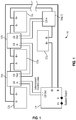
Figure 1 is a block diagram of a high voltage battery system incorporating a cascading contactor drive system in accordance with the invention; -
Figure 2 is a schematic representation of one embodiment of an interconnect circuit which may be utilized in the cascading contactor drive system ofFigure 1 ; and. -
Figure 3 is a schematic representation of another embodiment of an interconnect circuit, incorporating a driver circuit, which may be utilized in the cascading contactor drive system ofFigure 1 ; -
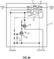
Figure 4a is a schematic representation of another embodiment of an interconnect circuit, adding one embodiment of a delay circuit to the driver circuit ofFigure 3 ; -
Figure 4b is a schematic representation of another embodiment of an interconnect circuit, adding another embodiment of a delay circuit to the driver circuit ofFigure 3 ; -
Figure 5 is a schematic representation of an interconnect circuit including a contactor driver, delay and power out; -
Figure 6 is a schematic representation of an interconnect circuit including a contactor driver, delay, power out and LED; and -
Figure 7 is a block diagram of a high voltage battery system incorporating a dual interconnect cascading contactor drive system in accordance with the invention - While this invention is susceptible of embodiment in many different forms, there will be described herein in detail, specific embodiments thereof with the understanding that the present disclosure is to be considered exemplifications of the principles of the invention and is not intended to limit the invention to the specific embodiments illustrated.
- Various methods of creating this cascading effect are contemplated.
- A high voltage battery system, generally designated 10, is illustrated in
Figure 1 . Thebattery system 10 includes a plurality of battery modules, such as afirst battery module 12a, asecond battery module 12b, athird battery module 12c, through to an nth battery module 12n (collectively, the battery modules 12). The battery modules 12 may each have a nominal voltage of thirty-two (32) volts DC, and the battery modules 12 may be coupled in series. Each of the battery modules may have conventional positive and negative power terminals B+ and B-, respectively. - The
battery control system 10 includes acontrol module 14. Thebattery system 10 further includes a plurality of interconnect controllers (collectively the interconnect controllers 16), such as afirst interconnect controller 16a, asecond interconnect controller 16b, through to an n-1th interconnect controller 16(n-1), respectively disposed between the "n" battery modules 12. Thecontrol module 14 includes power output terminals (P+, P-) which provide system output DC power in a conventional manner, such as to a load (not shown). If the battery modules 12 each have a power output of thirty-two (32) volts DC, the power provided at the power output terminals P+, P-, would be thirty-two (32) times "n," where "n" equals the number of battery modules 12 coupled thereto in series. - A first embodiment of an interconnect controller 161 is illustrated in
Figure 2 . The interconnect controller 161 is disposed between two of the battery modules 12. - As illustrated in
Figure 2 , the interconnect controller 161 includes an electromagnetic switch, or contactor, 18 having anactuating coil 20, amain contact 22 and anauxiliary contact 24. Themain contact 22 is electrically coupled between the power output of one of the battery modules 12 and the power input of another, serially coupled, one of the battery modules 12. - In the case of the
first interconnect controller 16a ofFigure 1 , theauxiliary contact 24 has an input coupled to a control output of thecontrol module 14, and an output coupled to a control input of the serially,downstream interconnect controller 16b. In the case of thesecond interconnect controller 16b ofFigure 1 , and other ones of the serially subsequent interconnect controllers 16, theauxiliary contact 24 has a control input coupled to a control output of a preceding interconnect controller 16, and a control output coupled to a control input of a serially downstream interconnect controller 16. - As discussed below, the control signal generated by the
control module 14 is serially passed through the serially connected interconnect controllers 16, as the respective ones of theauxiliary contacts 24 sequentially close. - Specifically, the control module 14 (
Fig.1 ) provides, upon command, an initial drive, or control, signal from its control out (Ctl Out) output. The voltage/current magnitude of the drive signal may be dependent upon requirements of the particular contactor utilized. - Still referring to
Figure 2 , the first interconnect controller 161 responds to the initial drive signal to energize thecoil 20 of thecontactor 18. As is known, energization of thecoil 20 by the initial drive signal closes both themain contact 22 and theauxiliary contact 24. Closure of themain contact 22 couples the power output of the preceding battery module 12 to the serially subsequent battery module 12. Then after the interconnect controller 161 senses that thecontactor 18 is closed, via closure of theauxiliary contactor 24, the interconnect controller 161 sends the control signal to the next one of the interconnect controllers 161, and so on. In this way the energy necessary to close a first one of thecontactors 18 is already expended before the next one of thecontactors 18 is driven, so the current demand to close subsequent ones of thecontactors 18 remains an amount relatively equivalent to the amount required to drive a single contactor. - A second embodiment of an interconnect controller 162 is illustrated in
Figure 3 . The second embodiment of the interconnect controller 162 may include a driver circuit, generally designated 25, including first and second, conventionallybiased MOSFET transistors driver circuit 25 may provide a relatively inexpensive way to simplify a battery module isolation system on a high voltage battery. According to the second embodiment of the interconnect controller 162, the Control In signal closes themain contactor 22 and theauxiliary contactor 24. The Control In signal passes through theauxiliary contactor 24 to thedriver circuit 25, which then passes out to the Control Out lines, to the serially next one of the interconnect controllers 16. A third embodiment of an interconnect controller 163 is illustrated inFigure 4a . According to the third embodiment of an interconnect controller 163, acapacitor 32 may be added to thedriver circuit 25, to add a delay to thedriver circuit 25 passing the Control In signal to the serially next interconnect controller 16. - A fourth embodiment of an interconnect controller 164 is illustrated in
Figure 4b . According to the fourth embodiment of the interconnect controller 164, amicroprocessor 34 may be added to thedriver circuit 25 to add a programmable delay to thedriver circuit 25 passing the Control In signal to the serially next interconnect controller 16. - A fifth embodiment of an interconnect controller 165 is illustrated in
Figure 5 . According to the fifth embodiment of the interconnect controller 165, Power Out lines may be provided, such as coupled to an output of thedriver circuit 25, such as to run a cell monitor for that stage. - A sixth embodiment of an interconnect controller 166 is illustrated in
Figure 6 . According to the sixth embodiment of the interconnect controller 166, anLED 44 may be provided at the output of thedriver circuit 25 to visually indicate engagement of thecontactor 18. - Referring to
Figure 7 , acontactor 18 may be provided on both the positive and negative power terminals of each of the interconnect controllers 16, further isolating each of the battery modules 12 where such isolation may be desired or otherwise required, such as for human safety. As illustrated inFigure 7 , the auxiliary outputs of associatedcontactors 18 may first be input to an ANDgate 40, prior to input to the associateddriver circuit 25. - It is to be understood that this disclosure is not intended to limit the invention to any particular form described, but to the contrary, the invention is intended to include all modifications, alternatives and equivalents falling within the scope of the inventior, which is defined in the appended claims.
Claims (10)
- A system for providing DC power to a load, the system comprising:first, second and third battery modules (12a, 12b, 12c), wherein each of the first, second and third battery modules includes a first power output terminal (B+) and a second power output terminal (B-), each of the first power output terminals being of a first polarity and the each of the second power output terminals being of a second, opposite polarity;a control module (14) having a control module output for providing a control signal; a first interconnect controller (16a) electrically disposed between the first (12a) and second (12b) battery modules, the first interconnect controller including a first control input and a first control output, a first actuating coil (20) having a first coil input and a first coil output, a first main contact (22) having a first main contact input and a first main contact output, and a first auxiliary contact (24) having a first auxiliary contact input and a first auxiliary contact output, wherein the first control input is coupled to the control module output to operably receive the control signal, the first coil input is coupled to the first control input, the first main contact input is coupled to the first power output terminal of the first battery module (12a) and the first main contact output is coupled to the second power output terminal of the second battery module (12b), and the first auxiliary contact input is coupled to the first control input, and the first auxiliary contact output is coupled to first control output;a second interconnect controller (16b) electrically disposed between the second (12b) and third (12c) battery modules, the second interconnect controller including a second control input, a second actuating coil (20) having a second coil input, and a second main contact (22) having a second main contact input and a second main contact output, wherein the second control input is coupled to the first control output, the second main contact input is coupled to the first power output terminal of the second battery module (12b) and the second main contact output is coupled to the second power output terminal of the third battery module (12c);wherein actuation of the control signal by the control module (14) is adapted to energize the first actuating coil (20) of the first interconnect controller (16a), which is adapted to close the first main contact (22) of the first interconnect controller (16a) to couple the first battery module (12a) to the second battery module (12b), and to close the first auxiliary contact (24)of the first interconnect controller (16a) to pass the control signal to the second control input of the second interconnect controller (16b) when the first auxiliary contact (24) of the first interconnect controller (16a) closes, wherein the control signal passed by the first auxiliary contact (24) of the first interconnect controller (16a) is adapted to energize the second actuating coil (20) of the second interconnect controller (16b), which is adapted to close the second main contact (22) of the second interconnect controller (16b) and to couple the third battery module (12c) to the first (12a) and second (12b) battery modules.
- The system of claim 1, wherein the first polarity is positive.
- The system of claim 1, including a driver circuit (25) coupled between the first auxiliary contact output and the first control output for isolating the battery modules (12a, 12b, 12c) from the control signal.
- The system of claim 3, wherein the driver circuit includes means for delaying the control signal passing to the first control output.
- The system of claim 3, wherein the driver circuit comprises MOSFET transistors.
- The system of claim 5, wherein the driver circuit includes a capacitor (32) for delaying the control signal passing to the first control output.
- The system of claim 5, wherein the driver circuit includes a microprocessor (34) for delaying the control signal passing to the first control output.
- The system of claim 4, including an output from the driver circuit for monitoring a cell stage.
- The system of claim 4, including an LED (44) coupled to the driver circuit for indicating engagement of the main (22) and auxiliary (24) contacts.
- The system of claim 1, including a third interconnect controller (16), and wherein the actuating coil (24) of the second interconnect controller (16b) responds to the passed control signal to close the respective auxiliary contact (24) of the second interconnect controller (16b) to pass the control signal to the third interconnect controller.
Applications Claiming Priority (2)
| Application Number | Priority Date | Filing Date | Title |
|---|---|---|---|
| US201762546805P | 2017-08-17 | 2017-08-17 | |
| PCT/US2018/046880 WO2019036595A1 (en) | 2017-08-17 | 2018-08-17 | Cascading contactor drive system |
Publications (2)
| Publication Number | Publication Date |
|---|---|
| EP3665759A1 EP3665759A1 (en) | 2020-06-17 |
| EP3665759B1 true EP3665759B1 (en) | 2021-10-06 |
Family
ID=63586861
Family Applications (1)
| Application Number | Title | Priority Date | Filing Date |
|---|---|---|---|
| EP18769889.9A Not-in-force EP3665759B1 (en) | 2017-08-17 | 2018-08-17 | Cascading contactor drive system |
Country Status (6)
| Country | Link |
|---|---|
| US (1) | US10847332B2 (en) |
| EP (1) | EP3665759B1 (en) |
| JP (1) | JP2020532260A (en) |
| KR (1) | KR102284939B1 (en) |
| CN (1) | CN111149273A (en) |
| WO (1) | WO2019036595A1 (en) |
Families Citing this family (6)
| Publication number | Priority date | Publication date | Assignee | Title |
|---|---|---|---|---|
| JP6960898B2 (en) * | 2018-10-31 | 2021-11-05 | 株式会社豊田中央研究所 | Power supply |
| JP6898904B2 (en) | 2018-10-31 | 2021-07-07 | 株式会社豊田中央研究所 | Power supply |
| CN110266295A (en) * | 2019-07-31 | 2019-09-20 | 深圳市风云实业有限公司 | A kind of circuit and method for realizing fast optical switch control based on metal-oxide-semiconductor |
| US11511632B2 (en) * | 2020-09-29 | 2022-11-29 | GM Global Technology Operations LLC | Electric powertrain with battery system having multi-pole high-voltage contactor |
| US12119688B2 (en) | 2022-08-23 | 2024-10-15 | Caterpillar Inc. | Dual pole high voltage disconnect |
| KR20260043163A (en) * | 2024-09-24 | 2026-03-31 | 주식회사 엘지에너지솔루션 | Signal output device and battery system including the same |
Family Cites Families (15)
| Publication number | Priority date | Publication date | Assignee | Title |
|---|---|---|---|---|
| PL129125B1 (en) | 1981-02-23 | 1984-04-30 | Akad Rolnicza Poznaniu | Method of obtaining a cellulose preparation |
| JPS60219919A (en) * | 1984-04-13 | 1985-11-02 | 株式会社日立製作所 | Power on method |
| JPH08322103A (en) * | 1995-05-22 | 1996-12-03 | Hiroshi Shirahama | Electric motor drive |
| US5969503A (en) * | 1998-01-12 | 1999-10-19 | Lucent Technologies Inc. | Unified contactor control system for battery plant and method of operation thereof |
| FR2818820B1 (en) * | 2000-12-21 | 2003-03-07 | Eads Airbus Sa | ELECTRIC POWER DISTRIBUTION SYSTEM AND CONTACTOR FOR SUCH A SYSTEM |
| US6599655B2 (en) * | 2001-04-06 | 2003-07-29 | The Boeing Company | Procedure for performing battery reconditioning on a space vehicle designed with one battery |
| CA2728383C (en) * | 2008-06-30 | 2015-04-14 | Abb Research Ltd | A battery unit arrangement for high voltage applications, connector and disconnector arrangement and method |
| CN102029914B (en) * | 2010-11-29 | 2013-07-24 | 北京汽车新能源汽车有限公司 | Electric automobile high-voltage safety device and control method |
| KR101219240B1 (en) * | 2011-01-31 | 2013-01-08 | 로베르트 보쉬 게엠베하 | Battery pack |
| KR101539693B1 (en) * | 2012-10-04 | 2015-07-27 | 주식회사 엘지화학 | Apparatus for waking up multi-bms |
| PL229845B1 (en) * | 2012-11-12 | 2018-08-31 | Branzowy Osrodek Badawczo Rozwojowy Masz Elektrycznych Komel | Modular battery pack |
| US9537351B2 (en) * | 2013-12-31 | 2017-01-03 | Lite-On, Inc. | Dual input power supply system and method |
| US10014697B2 (en) * | 2014-09-10 | 2018-07-03 | Nec Energy Solutions, Inc. | Control method for disconnecting switches integrated in series-connected batteries |
| JP6479383B2 (en) * | 2014-09-22 | 2019-03-06 | 株式会社東芝 | Vehicle storage battery system |
| US9702937B2 (en) * | 2015-02-17 | 2017-07-11 | Lg Chem, Ltd. | Contactor control system |
-
2018
- 2018-08-17 EP EP18769889.9A patent/EP3665759B1/en not_active Not-in-force
- 2018-08-17 US US16/104,297 patent/US10847332B2/en not_active Expired - Fee Related
- 2018-08-17 CN CN201880063818.4A patent/CN111149273A/en active Pending
- 2018-08-17 KR KR1020207007268A patent/KR102284939B1/en not_active Expired - Fee Related
- 2018-08-17 JP JP2020509500A patent/JP2020532260A/en active Pending
- 2018-08-17 WO PCT/US2018/046880 patent/WO2019036595A1/en not_active Ceased
Also Published As
| Publication number | Publication date |
|---|---|
| CN111149273A (en) | 2020-05-12 |
| JP2020532260A (en) | 2020-11-05 |
| KR102284939B1 (en) | 2021-08-04 |
| KR20200038988A (en) | 2020-04-14 |
| US10847332B2 (en) | 2020-11-24 |
| WO2019036595A1 (en) | 2019-02-21 |
| US20190057828A1 (en) | 2019-02-21 |
| EP3665759A1 (en) | 2020-06-17 |
Similar Documents
| Publication | Publication Date | Title |
|---|---|---|
| EP3665759B1 (en) | Cascading contactor drive system | |
| US11104232B2 (en) | Safe energy supply device for a vehicle | |
| US10326177B2 (en) | Apparatus for controlling the charging of electric vehicle | |
| JP7102773B2 (en) | Vehicle power supply system | |
| EP2559094B1 (en) | Battery with cell balancing | |
| DE102012210603B4 (en) | Battery safety concept | |
| EP1973214A2 (en) | Multi-functional LRM performing SSPC and ELCU functions | |
| US20170302091A1 (en) | Electric actuator with pre-heating | |
| CN109649216A (en) | Automatic connection of drive battery | |
| CN110382287B (en) | Drive system for a vehicle, method for operating a drive system and use of the drive system | |
| KR20200064012A (en) | Power supply system | |
| JP2020532260A5 (en) | ||
| US20210044121A1 (en) | Cascading Contactor Drive System | |
| CN101494135B (en) | Relay circuit | |
| US6597154B2 (en) | Electrical energy distribution system and contactor for such a system | |
| CN110914096A (en) | Energy storage system and method for electrically separating at least one first energy storage unit | |
| EP2533424B1 (en) | Solid state contactor assembly | |
| EP3038226B1 (en) | System and method for supplying electric power | |
| US20150175105A1 (en) | Drive system for a traction vehicle | |
| US9050981B2 (en) | System and method for providing fault mitigation for vehicle systems having high and low side drivers | |
| CN202840606U (en) | Power supply unit including safety mechanism | |
| DE102014201196A1 (en) | Method for operating a battery management system and battery management system | |
| CN222050754U (en) | Drive circuit, drive control device, ship, and vehicle | |
| CN109164384A (en) | Motor stator insulated ageing test apparatus and test method | |
| CN119813409A (en) | High voltage storage including emergency shut-off device for bistable contactors |
Legal Events
| Date | Code | Title | Description |
|---|---|---|---|
| STAA | Information on the status of an ep patent application or granted ep patent |
Free format text: STATUS: UNKNOWN |
|
| STAA | Information on the status of an ep patent application or granted ep patent |
Free format text: STATUS: THE INTERNATIONAL PUBLICATION HAS BEEN MADE |
|
| PUAI | Public reference made under article 153(3) epc to a published international application that has entered the european phase |
Free format text: ORIGINAL CODE: 0009012 |
|
| STAA | Information on the status of an ep patent application or granted ep patent |
Free format text: STATUS: REQUEST FOR EXAMINATION WAS MADE |
|
| 17P | Request for examination filed |
Effective date: 20200311 |
|
| AK | Designated contracting states |
Kind code of ref document: A1 Designated state(s): AL AT BE BG CH CY CZ DE DK EE ES FI FR GB GR HR HU IE IS IT LI LT LU LV MC MK MT NL NO PL PT RO RS SE SI SK SM TR |
|
| AX | Request for extension of the european patent |
Extension state: BA ME |
|
| DAV | Request for validation of the european patent (deleted) | ||
| DAX | Request for extension of the european patent (deleted) | ||
| GRAP | Despatch of communication of intention to grant a patent |
Free format text: ORIGINAL CODE: EPIDOSNIGR1 |
|
| STAA | Information on the status of an ep patent application or granted ep patent |
Free format text: STATUS: GRANT OF PATENT IS INTENDED |
|
| RIC1 | Information provided on ipc code assigned before grant |
Ipc: H02J 7/00 20060101AFI20210505BHEP Ipc: B60L 3/00 20190101ALI20210505BHEP Ipc: B60L 58/18 20190101ALI20210505BHEP Ipc: B60L 58/19 20190101ALI20210505BHEP |
|
| INTG | Intention to grant announced |
Effective date: 20210608 |
|
| GRAS | Grant fee paid |
Free format text: ORIGINAL CODE: EPIDOSNIGR3 |
|
| GRAA | (expected) grant |
Free format text: ORIGINAL CODE: 0009210 |
|
| STAA | Information on the status of an ep patent application or granted ep patent |
Free format text: STATUS: THE PATENT HAS BEEN GRANTED |
|
| AK | Designated contracting states |
Kind code of ref document: B1 Designated state(s): AL AT BE BG CH CY CZ DE DK EE ES FI FR GB GR HR HU IE IS IT LI LT LU LV MC MK MT NL NO PL PT RO RS SE SI SK SM TR |
|
| REG | Reference to a national code |
Ref country code: GB Ref legal event code: FG4D |
|
| REG | Reference to a national code |
Ref country code: CH Ref legal event code: EP Ref country code: AT Ref legal event code: REF Ref document number: 1437033 Country of ref document: AT Kind code of ref document: T Effective date: 20211015 |
|
| REG | Reference to a national code |
Ref country code: DE Ref legal event code: R096 Ref document number: 602018024733 Country of ref document: DE |
|
| REG | Reference to a national code |
Ref country code: IE Ref legal event code: FG4D |
|
| REG | Reference to a national code |
Ref country code: LT Ref legal event code: MG9D |
|
| REG | Reference to a national code |
Ref country code: NL Ref legal event code: MP Effective date: 20211006 |
|
| REG | Reference to a national code |
Ref country code: AT Ref legal event code: MK05 Ref document number: 1437033 Country of ref document: AT Kind code of ref document: T Effective date: 20211006 |
|
| PG25 | Lapsed in a contracting state [announced via postgrant information from national office to epo] |
Ref country code: RS Free format text: LAPSE BECAUSE OF FAILURE TO SUBMIT A TRANSLATION OF THE DESCRIPTION OR TO PAY THE FEE WITHIN THE PRESCRIBED TIME-LIMIT Effective date: 20211006 Ref country code: LT Free format text: LAPSE BECAUSE OF FAILURE TO SUBMIT A TRANSLATION OF THE DESCRIPTION OR TO PAY THE FEE WITHIN THE PRESCRIBED TIME-LIMIT Effective date: 20211006 Ref country code: FI Free format text: LAPSE BECAUSE OF FAILURE TO SUBMIT A TRANSLATION OF THE DESCRIPTION OR TO PAY THE FEE WITHIN THE PRESCRIBED TIME-LIMIT Effective date: 20211006 Ref country code: BG Free format text: LAPSE BECAUSE OF FAILURE TO SUBMIT A TRANSLATION OF THE DESCRIPTION OR TO PAY THE FEE WITHIN THE PRESCRIBED TIME-LIMIT Effective date: 20220106 Ref country code: AT Free format text: LAPSE BECAUSE OF FAILURE TO SUBMIT A TRANSLATION OF THE DESCRIPTION OR TO PAY THE FEE WITHIN THE PRESCRIBED TIME-LIMIT Effective date: 20211006 |
|
| PG25 | Lapsed in a contracting state [announced via postgrant information from national office to epo] |
Ref country code: IS Free format text: LAPSE BECAUSE OF FAILURE TO SUBMIT A TRANSLATION OF THE DESCRIPTION OR TO PAY THE FEE WITHIN THE PRESCRIBED TIME-LIMIT Effective date: 20220206 Ref country code: SE Free format text: LAPSE BECAUSE OF FAILURE TO SUBMIT A TRANSLATION OF THE DESCRIPTION OR TO PAY THE FEE WITHIN THE PRESCRIBED TIME-LIMIT Effective date: 20211006 Ref country code: PT Free format text: LAPSE BECAUSE OF FAILURE TO SUBMIT A TRANSLATION OF THE DESCRIPTION OR TO PAY THE FEE WITHIN THE PRESCRIBED TIME-LIMIT Effective date: 20220207 Ref country code: PL Free format text: LAPSE BECAUSE OF FAILURE TO SUBMIT A TRANSLATION OF THE DESCRIPTION OR TO PAY THE FEE WITHIN THE PRESCRIBED TIME-LIMIT Effective date: 20211006 Ref country code: NO Free format text: LAPSE BECAUSE OF FAILURE TO SUBMIT A TRANSLATION OF THE DESCRIPTION OR TO PAY THE FEE WITHIN THE PRESCRIBED TIME-LIMIT Effective date: 20220106 Ref country code: NL Free format text: LAPSE BECAUSE OF FAILURE TO SUBMIT A TRANSLATION OF THE DESCRIPTION OR TO PAY THE FEE WITHIN THE PRESCRIBED TIME-LIMIT Effective date: 20211006 Ref country code: LV Free format text: LAPSE BECAUSE OF FAILURE TO SUBMIT A TRANSLATION OF THE DESCRIPTION OR TO PAY THE FEE WITHIN THE PRESCRIBED TIME-LIMIT Effective date: 20211006 Ref country code: HR Free format text: LAPSE BECAUSE OF FAILURE TO SUBMIT A TRANSLATION OF THE DESCRIPTION OR TO PAY THE FEE WITHIN THE PRESCRIBED TIME-LIMIT Effective date: 20211006 Ref country code: GR Free format text: LAPSE BECAUSE OF FAILURE TO SUBMIT A TRANSLATION OF THE DESCRIPTION OR TO PAY THE FEE WITHIN THE PRESCRIBED TIME-LIMIT Effective date: 20220107 Ref country code: ES Free format text: LAPSE BECAUSE OF FAILURE TO SUBMIT A TRANSLATION OF THE DESCRIPTION OR TO PAY THE FEE WITHIN THE PRESCRIBED TIME-LIMIT Effective date: 20211006 |
|
| REG | Reference to a national code |
Ref country code: DE Ref legal event code: R097 Ref document number: 602018024733 Country of ref document: DE |
|
| PG25 | Lapsed in a contracting state [announced via postgrant information from national office to epo] |
Ref country code: SM Free format text: LAPSE BECAUSE OF FAILURE TO SUBMIT A TRANSLATION OF THE DESCRIPTION OR TO PAY THE FEE WITHIN THE PRESCRIBED TIME-LIMIT Effective date: 20211006 Ref country code: SK Free format text: LAPSE BECAUSE OF FAILURE TO SUBMIT A TRANSLATION OF THE DESCRIPTION OR TO PAY THE FEE WITHIN THE PRESCRIBED TIME-LIMIT Effective date: 20211006 Ref country code: RO Free format text: LAPSE BECAUSE OF FAILURE TO SUBMIT A TRANSLATION OF THE DESCRIPTION OR TO PAY THE FEE WITHIN THE PRESCRIBED TIME-LIMIT Effective date: 20211006 Ref country code: EE Free format text: LAPSE BECAUSE OF FAILURE TO SUBMIT A TRANSLATION OF THE DESCRIPTION OR TO PAY THE FEE WITHIN THE PRESCRIBED TIME-LIMIT Effective date: 20211006 Ref country code: DK Free format text: LAPSE BECAUSE OF FAILURE TO SUBMIT A TRANSLATION OF THE DESCRIPTION OR TO PAY THE FEE WITHIN THE PRESCRIBED TIME-LIMIT Effective date: 20211006 Ref country code: CZ Free format text: LAPSE BECAUSE OF FAILURE TO SUBMIT A TRANSLATION OF THE DESCRIPTION OR TO PAY THE FEE WITHIN THE PRESCRIBED TIME-LIMIT Effective date: 20211006 |
|
| PLBE | No opposition filed within time limit |
Free format text: ORIGINAL CODE: 0009261 |
|
| STAA | Information on the status of an ep patent application or granted ep patent |
Free format text: STATUS: NO OPPOSITION FILED WITHIN TIME LIMIT |
|
| 26N | No opposition filed |
Effective date: 20220707 |
|
| PG25 | Lapsed in a contracting state [announced via postgrant information from national office to epo] |
Ref country code: AL Free format text: LAPSE BECAUSE OF FAILURE TO SUBMIT A TRANSLATION OF THE DESCRIPTION OR TO PAY THE FEE WITHIN THE PRESCRIBED TIME-LIMIT Effective date: 20211006 |
|
| PG25 | Lapsed in a contracting state [announced via postgrant information from national office to epo] |
Ref country code: SI Free format text: LAPSE BECAUSE OF FAILURE TO SUBMIT A TRANSLATION OF THE DESCRIPTION OR TO PAY THE FEE WITHIN THE PRESCRIBED TIME-LIMIT Effective date: 20211006 |
|
| REG | Reference to a national code |
Ref country code: DE Ref legal event code: R119 Ref document number: 602018024733 Country of ref document: DE |
|
| PG25 | Lapsed in a contracting state [announced via postgrant information from national office to epo] |
Ref country code: MC Free format text: LAPSE BECAUSE OF FAILURE TO SUBMIT A TRANSLATION OF THE DESCRIPTION OR TO PAY THE FEE WITHIN THE PRESCRIBED TIME-LIMIT Effective date: 20211006 |
|
| REG | Reference to a national code |
Ref country code: CH Ref legal event code: PL |
|
| GBPC | Gb: european patent ceased through non-payment of renewal fee |
Effective date: 20220817 |
|
| PG25 | Lapsed in a contracting state [announced via postgrant information from national office to epo] |
Ref country code: LU Free format text: LAPSE BECAUSE OF NON-PAYMENT OF DUE FEES Effective date: 20220817 Ref country code: LI Free format text: LAPSE BECAUSE OF NON-PAYMENT OF DUE FEES Effective date: 20220831 Ref country code: CH Free format text: LAPSE BECAUSE OF NON-PAYMENT OF DUE FEES Effective date: 20220831 |
|
| REG | Reference to a national code |
Ref country code: BE Ref legal event code: MM Effective date: 20220831 |
|
| PG25 | Lapsed in a contracting state [announced via postgrant information from national office to epo] |
Ref country code: IT Free format text: LAPSE BECAUSE OF FAILURE TO SUBMIT A TRANSLATION OF THE DESCRIPTION OR TO PAY THE FEE WITHIN THE PRESCRIBED TIME-LIMIT Effective date: 20211006 |
|
| PG25 | Lapsed in a contracting state [announced via postgrant information from national office to epo] |
Ref country code: IE Free format text: LAPSE BECAUSE OF NON-PAYMENT OF DUE FEES Effective date: 20220817 Ref country code: FR Free format text: LAPSE BECAUSE OF NON-PAYMENT OF DUE FEES Effective date: 20220831 Ref country code: DE Free format text: LAPSE BECAUSE OF NON-PAYMENT OF DUE FEES Effective date: 20230301 |
|
| PG25 | Lapsed in a contracting state [announced via postgrant information from national office to epo] |
Ref country code: BE Free format text: LAPSE BECAUSE OF NON-PAYMENT OF DUE FEES Effective date: 20220831 |
|
| PG25 | Lapsed in a contracting state [announced via postgrant information from national office to epo] |
Ref country code: GB Free format text: LAPSE BECAUSE OF NON-PAYMENT OF DUE FEES Effective date: 20220817 |
|
| PG25 | Lapsed in a contracting state [announced via postgrant information from national office to epo] |
Ref country code: CY Free format text: LAPSE BECAUSE OF FAILURE TO SUBMIT A TRANSLATION OF THE DESCRIPTION OR TO PAY THE FEE WITHIN THE PRESCRIBED TIME-LIMIT Effective date: 20211006 |
|
| PG25 | Lapsed in a contracting state [announced via postgrant information from national office to epo] |
Ref country code: MK Free format text: LAPSE BECAUSE OF FAILURE TO SUBMIT A TRANSLATION OF THE DESCRIPTION OR TO PAY THE FEE WITHIN THE PRESCRIBED TIME-LIMIT Effective date: 20211006 Ref country code: HU Free format text: LAPSE BECAUSE OF FAILURE TO SUBMIT A TRANSLATION OF THE DESCRIPTION OR TO PAY THE FEE WITHIN THE PRESCRIBED TIME-LIMIT; INVALID AB INITIO Effective date: 20180817 |
|
| PG25 | Lapsed in a contracting state [announced via postgrant information from national office to epo] |
Ref country code: MT Free format text: LAPSE BECAUSE OF FAILURE TO SUBMIT A TRANSLATION OF THE DESCRIPTION OR TO PAY THE FEE WITHIN THE PRESCRIBED TIME-LIMIT Effective date: 20211006 |
|
| PG25 | Lapsed in a contracting state [announced via postgrant information from national office to epo] |
Ref country code: TR Free format text: LAPSE BECAUSE OF FAILURE TO SUBMIT A TRANSLATION OF THE DESCRIPTION OR TO PAY THE FEE WITHIN THE PRESCRIBED TIME-LIMIT Effective date: 20211006 |