EP3665459B2 - Piezoelektrische vorrichtung mit zumindest einem piezoelektrischen element - Google Patents
Piezoelektrische vorrichtung mit zumindest einem piezoelektrischen element Download PDFInfo
- Publication number
- EP3665459B2 EP3665459B2 EP18759239.9A EP18759239A EP3665459B2 EP 3665459 B2 EP3665459 B2 EP 3665459B2 EP 18759239 A EP18759239 A EP 18759239A EP 3665459 B2 EP3665459 B2 EP 3665459B2
- Authority
- EP
- European Patent Office
- Prior art keywords
- piezoelectric
- transition
- piezoelectric element
- piezoelectric device
- support
- Prior art date
- Legal status (The legal status is an assumption and is not a legal conclusion. Google has not performed a legal analysis and makes no representation as to the accuracy of the status listed.)
- Active
Links
Images
Classifications
-
- G—PHYSICS
- G01—MEASURING; TESTING
- G01L—MEASURING FORCE, STRESS, TORQUE, WORK, MECHANICAL POWER, MECHANICAL EFFICIENCY, OR FLUID PRESSURE
- G01L1/00—Measuring force or stress, in general
- G01L1/26—Auxiliary measures taken, or devices used, in connection with the measurement of force, e.g. for preventing influence of transverse components of force, for preventing overload
-
- C—CHEMISTRY; METALLURGY
- C04—CEMENTS; CONCRETE; ARTIFICIAL STONE; CERAMICS; REFRACTORIES
- C04B—LIME, MAGNESIA; SLAG; CEMENTS; COMPOSITIONS THEREOF, e.g. MORTARS, CONCRETE OR LIKE BUILDING MATERIALS; ARTIFICIAL STONE; CERAMICS; REFRACTORIES; TREATMENT OF NATURAL STONE
- C04B35/00—Shaped ceramic products characterised by their composition; Ceramics compositions; Processing powders of inorganic compounds preparatory to the manufacturing of ceramic products
- C04B35/515—Shaped ceramic products characterised by their composition; Ceramics compositions; Processing powders of inorganic compounds preparatory to the manufacturing of ceramic products based on non-oxide ceramics
- C04B35/58—Shaped ceramic products characterised by their composition; Ceramics compositions; Processing powders of inorganic compounds preparatory to the manufacturing of ceramic products based on non-oxide ceramics based on borides, nitrides, i.e. nitrides, oxynitrides, carbonitrides or oxycarbonitrides or silicides
- C04B35/583—Shaped ceramic products characterised by their composition; Ceramics compositions; Processing powders of inorganic compounds preparatory to the manufacturing of ceramic products based on non-oxide ceramics based on borides, nitrides, i.e. nitrides, oxynitrides, carbonitrides or oxycarbonitrides or silicides based on boron nitride
-
- G—PHYSICS
- G01—MEASURING; TESTING
- G01L—MEASURING FORCE, STRESS, TORQUE, WORK, MECHANICAL POWER, MECHANICAL EFFICIENCY, OR FLUID PRESSURE
- G01L1/00—Measuring force or stress, in general
- G01L1/16—Measuring force or stress, in general using properties of piezoelectric devices
-
- G—PHYSICS
- G01—MEASURING; TESTING
- G01L—MEASURING FORCE, STRESS, TORQUE, WORK, MECHANICAL POWER, MECHANICAL EFFICIENCY, OR FLUID PRESSURE
- G01L19/00—Details of, or accessories for, apparatus for measuring steady or quasi-steady pressure of a fluent medium insofar as such details or accessories are not special to particular types of pressure gauges
- G01L19/04—Means for compensating for effects of changes of temperature, i.e. other than electric compensation
-
- G—PHYSICS
- G01—MEASURING; TESTING
- G01L—MEASURING FORCE, STRESS, TORQUE, WORK, MECHANICAL POWER, MECHANICAL EFFICIENCY, OR FLUID PRESSURE
- G01L23/00—Devices or apparatus for measuring or indicating or recording rapid changes, such as oscillations, in the pressure of steam, gas, or liquid; Indicators for determining work or energy of steam, internal-combustion, or other fluid-pressure engines from the condition of the working fluid
- G01L23/08—Devices or apparatus for measuring or indicating or recording rapid changes, such as oscillations, in the pressure of steam, gas, or liquid; Indicators for determining work or energy of steam, internal-combustion, or other fluid-pressure engines from the condition of the working fluid operated electrically
- G01L23/10—Devices or apparatus for measuring or indicating or recording rapid changes, such as oscillations, in the pressure of steam, gas, or liquid; Indicators for determining work or energy of steam, internal-combustion, or other fluid-pressure engines from the condition of the working fluid operated electrically by pressure-sensitive members of the piezoelectric type
-
- G—PHYSICS
- G01—MEASURING; TESTING
- G01L—MEASURING FORCE, STRESS, TORQUE, WORK, MECHANICAL POWER, MECHANICAL EFFICIENCY, OR FLUID PRESSURE
- G01L9/00—Measuring steady of quasi-steady pressure of fluid or fluent solid material by electric or magnetic pressure-sensitive elements; Transmitting or indicating the displacement of mechanical pressure-sensitive elements, used to measure the steady or quasi-steady pressure of a fluid or fluent solid material, by electric or magnetic means
- G01L9/0041—Transmitting or indicating the displacement of flexible diaphragms
- G01L9/0051—Transmitting or indicating the displacement of flexible diaphragms using variations in ohmic resistance
- G01L9/0052—Transmitting or indicating the displacement of flexible diaphragms using variations in ohmic resistance of piezoresistive elements
-
- G—PHYSICS
- G01—MEASURING; TESTING
- G01L—MEASURING FORCE, STRESS, TORQUE, WORK, MECHANICAL POWER, MECHANICAL EFFICIENCY, OR FLUID PRESSURE
- G01L9/00—Measuring steady of quasi-steady pressure of fluid or fluent solid material by electric or magnetic pressure-sensitive elements; Transmitting or indicating the displacement of mechanical pressure-sensitive elements, used to measure the steady or quasi-steady pressure of a fluid or fluent solid material, by electric or magnetic means
- G01L9/0041—Transmitting or indicating the displacement of flexible diaphragms
- G01L9/008—Transmitting or indicating the displacement of flexible diaphragms using piezoelectric devices
-
- G—PHYSICS
- G01—MEASURING; TESTING
- G01P—MEASURING LINEAR OR ANGULAR SPEED, ACCELERATION, DECELERATION, OR SHOCK; INDICATING PRESENCE, ABSENCE, OR DIRECTION, OF MOVEMENT
- G01P15/00—Measuring acceleration; Measuring deceleration; Measuring shock, i.e. sudden change of acceleration
- G01P15/02—Measuring acceleration; Measuring deceleration; Measuring shock, i.e. sudden change of acceleration by making use of inertia forces using solid seismic masses
- G01P15/08—Measuring acceleration; Measuring deceleration; Measuring shock, i.e. sudden change of acceleration by making use of inertia forces using solid seismic masses with conversion into electric or magnetic values
- G01P15/09—Measuring acceleration; Measuring deceleration; Measuring shock, i.e. sudden change of acceleration by making use of inertia forces using solid seismic masses with conversion into electric or magnetic values by piezoelectric pick-up
-
- H—ELECTRICITY
- H10—SEMICONDUCTOR DEVICES; ELECTRIC SOLID-STATE DEVICES NOT OTHERWISE PROVIDED FOR
- H10N—ELECTRIC SOLID-STATE DEVICES NOT OTHERWISE PROVIDED FOR
- H10N30/00—Piezoelectric or electrostrictive devices
- H10N30/30—Piezoelectric or electrostrictive devices with mechanical input and electrical output, e.g. functioning as generators or sensors
- H10N30/302—Sensors
-
- H—ELECTRICITY
- H10—SEMICONDUCTOR DEVICES; ELECTRIC SOLID-STATE DEVICES NOT OTHERWISE PROVIDED FOR
- H10N—ELECTRIC SOLID-STATE DEVICES NOT OTHERWISE PROVIDED FOR
- H10N30/00—Piezoelectric or electrostrictive devices
- H10N30/80—Constructional details
- H10N30/85—Piezoelectric or electrostrictive active materials
- H10N30/853—Ceramic compositions
- H10N30/8561—Bismuth-based oxides
-
- H—ELECTRICITY
- H10—SEMICONDUCTOR DEVICES; ELECTRIC SOLID-STATE DEVICES NOT OTHERWISE PROVIDED FOR
- H10N—ELECTRIC SOLID-STATE DEVICES NOT OTHERWISE PROVIDED FOR
- H10N30/00—Piezoelectric or electrostrictive devices
- H10N30/80—Constructional details
- H10N30/88—Mounts; Supports; Enclosures; Casings
- H10N30/886—Additional mechanical prestressing means, e.g. springs
-
- C—CHEMISTRY; METALLURGY
- C04—CEMENTS; CONCRETE; ARTIFICIAL STONE; CERAMICS; REFRACTORIES
- C04B—LIME, MAGNESIA; SLAG; CEMENTS; COMPOSITIONS THEREOF, e.g. MORTARS, CONCRETE OR LIKE BUILDING MATERIALS; ARTIFICIAL STONE; CERAMICS; REFRACTORIES; TREATMENT OF NATURAL STONE
- C04B2235/00—Aspects relating to ceramic starting mixtures or sintered ceramic products
- C04B2235/02—Composition of constituents of the starting material or of secondary phases of the final product
- C04B2235/30—Constituents and secondary phases not being of a fibrous nature
- C04B2235/32—Metal oxides, mixed metal oxides, or oxide-forming salts thereof, e.g. carbonates, nitrates, (oxy)hydroxides, chlorides
- C04B2235/3231—Refractory metal oxides, their mixed metal oxides, or oxide-forming salts thereof
- C04B2235/3244—Zirconium oxides, zirconates, hafnium oxides, hafnates, or oxide-forming salts thereof
-
- C—CHEMISTRY; METALLURGY
- C04—CEMENTS; CONCRETE; ARTIFICIAL STONE; CERAMICS; REFRACTORIES
- C04B—LIME, MAGNESIA; SLAG; CEMENTS; COMPOSITIONS THEREOF, e.g. MORTARS, CONCRETE OR LIKE BUILDING MATERIALS; ARTIFICIAL STONE; CERAMICS; REFRACTORIES; TREATMENT OF NATURAL STONE
- C04B2235/00—Aspects relating to ceramic starting mixtures or sintered ceramic products
- C04B2235/02—Composition of constituents of the starting material or of secondary phases of the final product
- C04B2235/30—Constituents and secondary phases not being of a fibrous nature
- C04B2235/34—Non-metal oxides, non-metal mixed oxides, or salts thereof that form the non-metal oxides upon heating, e.g. carbonates, nitrates, (oxy)hydroxides, chlorides
- C04B2235/3409—Boron oxide, borates, boric acids, or oxide forming salts thereof, e.g. borax
-
- C—CHEMISTRY; METALLURGY
- C04—CEMENTS; CONCRETE; ARTIFICIAL STONE; CERAMICS; REFRACTORIES
- C04B—LIME, MAGNESIA; SLAG; CEMENTS; COMPOSITIONS THEREOF, e.g. MORTARS, CONCRETE OR LIKE BUILDING MATERIALS; ARTIFICIAL STONE; CERAMICS; REFRACTORIES; TREATMENT OF NATURAL STONE
- C04B2235/00—Aspects relating to ceramic starting mixtures or sintered ceramic products
- C04B2235/02—Composition of constituents of the starting material or of secondary phases of the final product
- C04B2235/30—Constituents and secondary phases not being of a fibrous nature
- C04B2235/34—Non-metal oxides, non-metal mixed oxides, or salts thereof that form the non-metal oxides upon heating, e.g. carbonates, nitrates, (oxy)hydroxides, chlorides
- C04B2235/3418—Silicon oxide, silicic acids or oxide forming salts thereof, e.g. silica sol, fused silica, silica fume, cristobalite, quartz or flint
-
- C—CHEMISTRY; METALLURGY
- C04—CEMENTS; CONCRETE; ARTIFICIAL STONE; CERAMICS; REFRACTORIES
- C04B—LIME, MAGNESIA; SLAG; CEMENTS; COMPOSITIONS THEREOF, e.g. MORTARS, CONCRETE OR LIKE BUILDING MATERIALS; ARTIFICIAL STONE; CERAMICS; REFRACTORIES; TREATMENT OF NATURAL STONE
- C04B2235/00—Aspects relating to ceramic starting mixtures or sintered ceramic products
- C04B2235/02—Composition of constituents of the starting material or of secondary phases of the final product
- C04B2235/30—Constituents and secondary phases not being of a fibrous nature
- C04B2235/38—Non-oxide ceramic constituents or additives
- C04B2235/3817—Carbides
- C04B2235/3826—Silicon carbides
-
- C—CHEMISTRY; METALLURGY
- C04—CEMENTS; CONCRETE; ARTIFICIAL STONE; CERAMICS; REFRACTORIES
- C04B—LIME, MAGNESIA; SLAG; CEMENTS; COMPOSITIONS THEREOF, e.g. MORTARS, CONCRETE OR LIKE BUILDING MATERIALS; ARTIFICIAL STONE; CERAMICS; REFRACTORIES; TREATMENT OF NATURAL STONE
- C04B2235/00—Aspects relating to ceramic starting mixtures or sintered ceramic products
- C04B2235/02—Composition of constituents of the starting material or of secondary phases of the final product
- C04B2235/30—Constituents and secondary phases not being of a fibrous nature
- C04B2235/38—Non-oxide ceramic constituents or additives
- C04B2235/3852—Nitrides, e.g. oxynitrides, carbonitrides, oxycarbonitrides, lithium nitride, magnesium nitride
- C04B2235/386—Boron nitrides
-
- C—CHEMISTRY; METALLURGY
- C04—CEMENTS; CONCRETE; ARTIFICIAL STONE; CERAMICS; REFRACTORIES
- C04B—LIME, MAGNESIA; SLAG; CEMENTS; COMPOSITIONS THEREOF, e.g. MORTARS, CONCRETE OR LIKE BUILDING MATERIALS; ARTIFICIAL STONE; CERAMICS; REFRACTORIES; TREATMENT OF NATURAL STONE
- C04B2235/00—Aspects relating to ceramic starting mixtures or sintered ceramic products
- C04B2235/02—Composition of constituents of the starting material or of secondary phases of the final product
- C04B2235/30—Constituents and secondary phases not being of a fibrous nature
- C04B2235/42—Non metallic elements added as constituents or additives, e.g. sulfur, phosphor, selenium or tellurium
- C04B2235/428—Silicon
-
- C—CHEMISTRY; METALLURGY
- C04—CEMENTS; CONCRETE; ARTIFICIAL STONE; CERAMICS; REFRACTORIES
- C04B—LIME, MAGNESIA; SLAG; CEMENTS; COMPOSITIONS THEREOF, e.g. MORTARS, CONCRETE OR LIKE BUILDING MATERIALS; ARTIFICIAL STONE; CERAMICS; REFRACTORIES; TREATMENT OF NATURAL STONE
- C04B2235/00—Aspects relating to ceramic starting mixtures or sintered ceramic products
- C04B2235/70—Aspects relating to sintered or melt-casted ceramic products
- C04B2235/72—Products characterised by the absence or the low content of specific components, e.g. alkali metal free alumina ceramics
- C04B2235/728—Silicon content
-
- C—CHEMISTRY; METALLURGY
- C04—CEMENTS; CONCRETE; ARTIFICIAL STONE; CERAMICS; REFRACTORIES
- C04B—LIME, MAGNESIA; SLAG; CEMENTS; COMPOSITIONS THEREOF, e.g. MORTARS, CONCRETE OR LIKE BUILDING MATERIALS; ARTIFICIAL STONE; CERAMICS; REFRACTORIES; TREATMENT OF NATURAL STONE
- C04B2235/00—Aspects relating to ceramic starting mixtures or sintered ceramic products
- C04B2235/70—Aspects relating to sintered or melt-casted ceramic products
- C04B2235/74—Physical characteristics
- C04B2235/76—Crystal structural characteristics, e.g. symmetry
- C04B2235/767—Hexagonal symmetry, e.g. beta-Si3N4, beta-Sialon, alpha-SiC or hexa-ferrites
Definitions
- the invention relates to a piezoelectric device with at least one piezoelectric element which has a support plane aligned with a force introduction element, wherein, upon thermal loading of the piezoelectric device in the support plane, expansion differences occur between the piezoelectric element and the force introduction element, wherein at least one transition element is arranged between the piezoelectric element and the force introduction element.
- Heating or cooling under compressive load or prestressing results in frictional sliding of the components against each other or in severe distortion of both the support and the measuring element, since isotropic and anisotropic materials can only be stretched in one direction at best.
- the material of a pressure piece or support was usually selected so that its coefficient of thermal expansion, as well as its coefficient of transverse expansion, lies between the respective extreme values of the crystal element—measured in the plane of the contact surface—so that a certain limitation of the distortion or sliding processes could be achieved.
- the stresses caused by the anisotropy and the different thermal expansion behavior can lead to the destruction of the support or the piezoelectric crystal element, the latter especially in disc-shaped measuring elements arranged in stacks of multiple measuring elements, as used in the so-called longitudinal piezoelectric effect (charge dissipation occurs in the pressure area).
- the frictional forces acting across the support or contact surfaces act on a relatively small cross-section of the crystal elements, which is normal to these forces, which can lead to fracture of the measuring elements under alternating thermal stress.
- strain on the crystal also influences its charge release, i.e., the measurement signal.
- strain on the crystal also influences its charge release, i.e., the measurement signal.
- frictional sliding can occur in parts of the pressure surface between the crystal element and the support, leading to hysteresis phenomena in the measurement signal, which, of course, must be avoided.
- the DE 196 51 227 A1 It is proposed to divide the piezoelectric measuring element or the end regions of both supports facing the piezoelectric measuring element into several rod-, roller-, or web-shaped elements, whereby the two supports and the piezoelectric measuring element exhibit essentially the same thermal expansion or transverse expansion in the longitudinal direction of the rod-, roller-, or web-shaped elements perpendicular to the direction of force application.
- the aforementioned problems are thus eliminated or minimized by an "anisotropic design" of the measuring element or support.
- the end regions of both supports facing the piezoelectric measuring element are made of an isotropic material and feature web-shaped elements or rollers whose thermal and transverse expansion in the longitudinal direction is adapted to that of the piezoelectric measuring element.
- the production of such end regions is complex, and adapting the thermal and transverse expansion in the longitudinal direction is not possible for many material combinations.
- an adaptation element is arranged on both sides of the piezoelectric element (e.g., made of GaPO4 ) in between the respective support element.
- Each of the adaptation elements e.g., also made of GaPO4
- the compensation of the different thermal expansion is used, for example, in the DE 102 17 164 A1 This is achieved with the help of matching elements whose optical z-axis is tilted by a specific angle relative to the contact surfaces or rotated around the y-axis.
- the thermal expansion in the projection direction lies between that of the piezoelectric element in the z-axis direction and that of the isotropic support.
- the projection of the optical z-axis of the matching element is aligned parallel or antiparallel to the optical z-axis of the piezoelectric element.
- Typical materials for the support have so far been nickel-based materials or insulating ceramics (e.g., Al 2 O 3 ), or sapphire.
- the object of the present invention is to improve the piezoelectric devices described above in such a way that shear stresses and shear forces in the areas between the force-introducing elements and the piezoelectric measuring element are minimized or largely avoided using the simplest possible measures. Furthermore, the quality of the measurement signal is to be improved, with particular emphasis on avoiding spontaneously occurring false signals caused by frictional sliding and slipping of the piezoelectric elements on their supports.
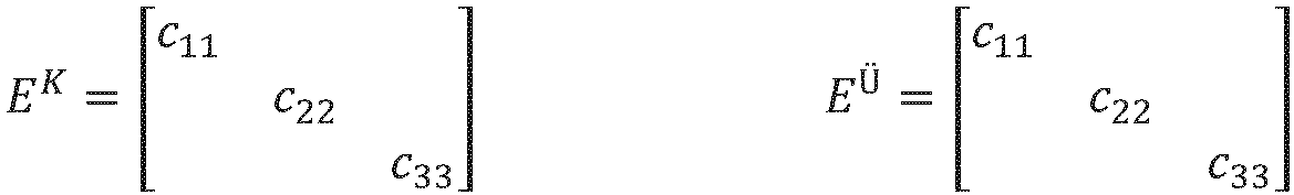
- this is achieved by the transition element having a modulus of elasticity whose modulus components c 22 , c 33 in the support plane are each smaller than the corresponding modulus of elasticity components of the piezoelectric element.
- the piezoelectric element "stretches” or “compresses” the transition element. This reduces the stress values in the piezoelectric element that could damage or tear the piezoelectric element.
- the at least one piezoelectric element in a piezoelectric device, can have an anisotropic thermal expansion and an anisotropic modulus of elasticity described by an elasticity tensor E K .
- the modulus of elasticity of the transition element is smaller than the components c 22 and c 33 of the elasticity tensor E K associated with the support plane.
- the component c 11 of the elasticity tensor relates to a direction (x-direction) normal to the support plane (yz-plane) and has no influence on the expansion differences in the support plane.
- the transition element has a compressive strength of at least 30%, preferably more than 90%, of the compressive strength of the piezoelectric element in the direction of a force acting on the piezoelectric element.
- the boron nitride transition element can be used in the piezoelectric device with its specific electrical resistance > 10 12 Ohm cm at the same time as an electrical insulating element.
- the Young's modulus of a transition element made of sintered hexagonal boron nitride, silicon carbide, and zirconium(IV) oxide ranges between 30 GPa and 45 GPa, with a compressive strength of over 100 MPa.
- the Young's modulus of GaPO4 is much higher in the support plane, namely 67 GPa along the y-axis and over 100 GPa along the z-axis, allowing the GaPO4 crystal to compress or stretch the transition element without breaking.
- the operating temperature of the sintered material extends up to 900°C in oxidizing atmospheres and up to 1800°C in inert atmospheres. It is therefore ideally suited for piezoelectric devices (e.g., for pressure sensors) in the high-temperature range above 600°C, as well as for special applications up to over 800°C.
- the transition element consists largely (approximately 50% to 70%) of sintered, hexagonal boron nitride (hBN) and can contain portions of silicon carbide (SiC), zirconium(IV) oxide (ZrO 2 ) and/or silicon oxide (SiO 2 ).
- boron oxide may be included as a binder, as well as traces of silicon and boric acid.
- the transition element may be preloaded together with the piezoelectric element to absorb shear forces normal to the preload direction.
- a transition element with an anisotropic modulus of elasticity e.g. hexagonal boron nitride with anisotropic modulus of elasticity
- anisotropic modulus of elasticity e.g. hexagonal boron nitride with anisotropic modulus of elasticity
- the piezoelectric element can be made of GaPO4 , langasite, langatate or tourmaline, for example, or of a piezoceramic, for example bismuth titanate.
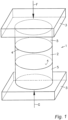
- the schematically illustrated piezoelectric device 1 has at least one piezoelectric element 2, for example a crystal element made of GaPO 4 , which has an anisotropic thermal expansion in its parallel support planes 4 aligned with the two force introduction elements 3, such that when the piezoelectric device 1 is subjected to thermal stress in the support planes 4, differences in expansion occur between the piezoelectric element 2 and the force introduction elements 3.
- a transition element 5 is arranged between the piezoelectric element 2 and the force introduction elements 3, the elastic modulus of which is smaller than the elastic modulus of the piezoelectric element 2 in its support plane 4.
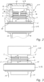
- the embodiment of the invention shown shows a pressure sensor 10 with a sensor membrane 11, wherein the lower force introduction element 3 is designed as a support 12 of the sensor 10.
- the upper force introduction element 3 is designed as a pressure piece 14 acted upon by the sensor membrane 11, wherein a first, disk-shaped transition element 5 is arranged between the support 12 and the lower piezoelectric element 2 of a stack of, for example, four piezo elements 2, and a second, disk-shaped transition element 5 is arranged between the upper, membrane-side piezoelectric element 2 and the pressure piece 14, so that the shear stresses and shear forces occurring in the critical support planes 4 of the edge-side piezo elements 2 can be effectively compensated.
- the central region of the membrane 11 can also bear directly against the membrane-side transition element 5.
- the transition elements 5 also serve as electrical insulation elements. Charges of the same name on the piezoelectric elements are collected via thin, ductile electrode sheets 16 made of a foil material and discharged via signal lines 17. Fig. 2 and Fig. 3 only the connecting loops of the electrode sheets 16 are visible.
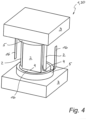
- the embodiment variant of a pressure sensor 30 shown essentially corresponds to the variant according to Fig. 2 , where the piezoelectric elements 2 are cuboid-shaped and arranged vertically using the transverse piezoelectric effect.
- the sensor housing and the sensor membrane have been omitted for clarity.
- the thickness of the transition element 5 is between 5% and 200%, preferably between 10% and 50%, of the height of the vertically arranged piezoelectric element 2.
- the electrical contact is made via thin electrode sheets 16 made of a foil material.
Landscapes
- Physics & Mathematics (AREA)
- General Physics & Mathematics (AREA)
- Chemical & Material Sciences (AREA)
- Engineering & Computer Science (AREA)
- Ceramic Engineering (AREA)
- Manufacturing & Machinery (AREA)
- Materials Engineering (AREA)
- Structural Engineering (AREA)
- Organic Chemistry (AREA)
- Combustion & Propulsion (AREA)
- Measuring Fluid Pressure (AREA)
Description
- Die Erfindung betrifft eine piezoelektrische Vorrichtung mit zumindest einem piezoelektrischen Element, welches eine zu einem Krafteinleitelement ausgerichtete Auflageebene aufweist, wobei bei einer thermischen Belastung der piezoelektrischen Vorrichtung in der Auflageebene Ausdehnungsunterschiede zwischen dem piezoelektrischen Element und dem Krafteinleitelement auftreten, wobei zwischen dem piezoelektrischen Element und dem Krafteinleitelement mindestens ein Übergangselement angeordnet ist.
- Bei Kraftmesselementen, Drucksensoren, Beschleunigungs- und Scherkraftsensoren die piezoelektrische Kristallelemente aufweisen, tritt eine Eigenschaft dieser Materialien negativ zutage, nämlich Ausdehnungsunterschiede zu angrenzenden Materialien bei thermischer Belastung, sowie die Anisotropie einiger Stoffwerte, wie Wärmedehnung oder Querdehnung unter mechanischer Spannung.
- An das eigentliche piezoelektrische Messelement schließt praktisch immer ein Gehäuse, ein Auflager, ein Druckstempel bzw. ein krafteinleitendes Element an, wobei bei diesen Bauteilen ein Wärmedehnverhalten oder Anisotropien in vergleichbarer Größe, wie bei vielen der in Frage kommenden Piezokristallen kaum zu finden sind. Insbesondere im Übergangsbereich vom anisotropen Kristallelement zum isotropen Auflager treten daher schädliche Scherkräfte und Scherspannungen auf. Einerseits kann dadurch das Kristallelement beim Aufheizen aufgrund der größeren Dehnung des Auflagermaterials zerreißen, andererseits erfolgt ein Rutschen des Kristallelements über die Auflage entlang der Kristallrichtung mit größeren Dehnung und ein anschließendes Zerreißen des Kristallelements beim Abkühlen.
- Bei der Erwärmung oder Abkühlung unter Druckbelastung bzw. Vorspannung kommt es zum reibungsbehafteten Gleiten der Bauteile aufeinander oder zu starken Verspannungen sowohl des Auflagers als auch des Messelementes, da isotropes und anisotropes Material bestenfalls in einer Richtung dehnungsangepasst sein können. Meist wurde bisher das Material eines Druckstückes oder Auflagers so gewählt, dass sein Wärmedehnungskoeffizient ebenso wie sein Querdehnungskoeffizient zwischen den jeweiligen Extremwerten des Kristallelements - gemessen in der Ebene der Kontaktfläche - liegt, sodass auf diese Weise eine gewisse Beschränkung der Verspannungen bzw. der Gleitvorgänge erreicht werden konnte.
- Die durch die Anisotropie und das unterschiedliche Wärmedehnverhalten hervorgerufenen Spannungen können zur Zerstörung des Auflagers oder des piezoelektrischen Kristallelements führen, letzteres vor allem bei scheibenförmigen Messelementen, angeordnet in Stapeln mit mehreren Messelementen, wie sie bei der Nutzung des sogenannten longitudinalen Piezoeffektes (Ladungsabnahme erfolgt in der Druckfläche) verwendet werden. Die über die Auflage- bzw. Kontaktflächen anliegenden Reibungskräfte wirken hier auf einen normal zu diesen Kräften verhältnismäßig geringen Querschnitt der Kristallelemente, was zum Bruch der Messelemente bei thermischer Wechselbelastung führen kann.
- Weiters wird durch Verspannungen des Kristalls auch dessen Ladungsabgabe, d.h. das Messsignal beeinflusst. Beispielsweise kann es in Teilen der Druckfläche zwischen Kristallelement und Auflager zu reibungsbehaftetem Gleiten und damit zu Hystereseerscheinungen im Messsignal kommen, die natürlich vermieden werden müssen.
- Im Zusammenhang mit dieser Problematik wird in der
DE 196 51 227 A1 vorgeschlagen, das piezoelektrische Messelement oder die dem piezoelektrischen Messelement zugekehrten Endbereiche beider Auflager in mehrere stab-, rollen- oder stegförmige Elemente zu unterteilen, wobei die beiden Auflager und das piezoelektrische Messelement in Längsrichtung der stab-, rollen- oder stegförmigen Elemente normal auf die Richtung der Krafteinleitung im Wesentlichen dieselbe Wärmedehnung oder Querdehnung aufweisen. Beseitigt bzw. minimiert werden die genannten Probleme somit durch eine "anisotrope Bauform" des Messelementes bzw. des Auflagers. - Beispielsweise weisen die dem piezoelektrischen Messelement zugekehrten Endbereiche beider Auflager aus einem isotropen Material stegförmige Elemente oder Rollen auf, deren Wärme- und Querdehnung in Längsrichtung an jene des piezoelektrischen Messelementes angepasst ist. Die Fertigung derartiger Endbereiche ist allerdings aufwändig und die Anpassung der Wärme- und Querdehnung in Längsrichtung für viele Materialkombinationen nicht möglich.
- Ein anderer Lösungsansatz wird in der
DE 102 17 164 B4 bzw. in deren OffenlegungsschriftDE 102 17 164 A1 beschrieben. Zur besseren Anpassung der thermischen Ausdehnung im Bereich der Kontaktflächen ist hier zu beiden Seiten des piezoelektrischen Elementes (z.B. aus GaPO4) in Zwischenlage zum jeweiligen Auflageelement ein Anpassungselement angeordnet. Jedes der Anpassungselemente (z.B. ebenfalls aus GaPO4) weist zumindest in der Ebene seiner beiden Kontaktflächen eine anisotrope thermische Ausdehnung auf, welche in der Richtung der maximalen Ausdehnungsunterschiede (beispielsweise in Richtung der z-Achse des piezoelektrischen Elementes) zwischen jener des piezoelektrischen Elementes und des isotropen Auflageelementes liegt. - Der Ausgleich der unterschiedlichen thermischen Ausdehnung wird beispielsweise in der
DE 102 17 164 A1 mit Hilfe von Anpassungselementen erreicht, deren optische z-Achse in Bezug auf die Kontaktflächen um einen bestimmten Winkel gekippt bzw. um die y-Achse gedreht ist. Die thermische Ausdehnung in Richtung der Projektion (Projektion der z-Achse auf die Kontaktfläche) liegt zwischen jener des piezoelektrischen Elementes in Richtung z-Achse und jener der isotropen Auflage. Weiters ist die Projektion der optischen z-Achse des Anpassungselementes parallel oder antiparallel zur optischen z-Achse des piezoelektrischen Elementes ausgerichtet. - Dieser Lösungsansatz ist jedoch aufwändig und lässt sich nicht immer erfolgreich umsetzen, zumal bisher die Meinung vorherrschte, dass das Auflager möglichst hart ausgeführt sein muss. Typische Materialien für das Auflager waren bisher Nickel-Basiswerkstoffe oder isolierende Keramiken (z.B. Al2O3) oder Saphir.
- Aufgabe der vorliegenden Erfindung ist es, die eingangs beschriebenen piezoelektrischen Vorrichtungen derart zu verbessern, dass Scherspannungen und Scherkräfte in den Bereichen zwischen den krafteinleitenden Elementen und dem piezoelektrischen Messelement mit möglichst einfachen Maßnahmen minimiert bzw. weitgehend vermieden werden. Weiters soll die Qualität des Messsignals verbessert werden, wobei insbesondere spontan auftretende Fehlsignale, hervorgerufen durch reibungsbehaftetes Gleiten und Rutschen der piezoelektrischen Elemente an deren Auflagen, vermieden werden soll.
- Erfindungsgemäß wird dies dadurch erreicht, dass das Übergangselement einen E-Modul aufweist, dessen E-Modul-Komponenten c22, c33 in der Auflageebene jeweils kleiner sind, als die entsprechenden E-Modul-Komponenten des piezoelektrischen Elements. Dadurch "dehnt" oder "staucht" das piezoelektrische Element das Übergangselement. Es reduzieren sich daher im piezoelektrischen Element die Spannungswerte, die das piezoelektrische Element schädigen oder zerreißen könnten.
- Im Unterschied zu der aus der
DE 102 17 164 A1 bekannten Problemlösung (Anpassung der thermischen Ausdehnungskoeffizienten), werden bei der Erfindung unerwünschte Scherspannungen und Scherkräfte in der Auflageebene mit Hilfe eines Übergangselements minimiert, dessen Elastizitätsmodul die in Anspruch 1 dargelegten Merkmale aufweist. - Erfindungsgemäß kann bei einer piezoelektrischen Vorrichtung, das zumindest eine piezoelektrische Element eine anisotrope thermische Ausdehnung und einen durch einen Elastizitätstensor EK beschreibbaren, anisotropen E-Modul aufweisen. Dabei ist der E-Modul des Übergangselements kleiner als die der Auflageebene zugeordneten Komponenten c22 und c33 des Elastizitätstensors EK.
- Falls auch das Übergangsmaterial, beispielsweise ein Sinterkörper, einen anisotropen E-Modul aufweist, der durch einen Elastizitätstensor EÜ beschreibbar ist, mit
- Zur möglichst verlustfreien Übertragung der Druckkräfte in das piezoelektrische Element weist das Übergangselement in Richtung einer auf das piezoelektrische Element einwirkenden Kraft eine Druckfestigkeit von zumindest 30%, vorzugsweise von über 90%, der Druckfestigkeit des piezoelektrischen Elements auf.
- Überraschenderweise hat sich gezeigt, dass die geforderten Materialeigenschaften für das Übergangselement (kleiner E-Modul bei gleichzeitig hoher Druckfestigkeit) von einem Sintermaterial erfüllt werden, das großteils (ca. 50% bis 70%) aus gesintertem, hexagonalem Bornitrid besteht (Bezugsquelle: z.B.: HENZE Boron Nitride Products, siehe: www.henze-bnp.de).
- Das Übergangselement aus Bornitrid kann in der piezoelektrischen Vorrichtung mit seinem spezifischen elektrischen Widerstand > 1012 Ohm cm gleichzeitig als elektrisches Isolierelement eingesetzt werden.
- Beispielsweise gilt für GaPO4 und einen BN Sinterwerkstoff für den anisotropen E-Modul [GPa]
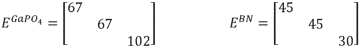
- Der E-Modul eines Übergangselementes aus gesintertem hexagonalem Bornitrid, Siliciumcarbid und Zirconuim (IV)oxid liegt zwischen 30 GPa und 45 GPa bei einer Druckfestigkeit von über 100 MPa. Der E-Modul von GaPO4 liegt in der Auflageebene bei viel größeren Werten, nämlich in der y-Achse bei 67 GPa und in der z-Achse bei über 100 GPa, sodass der GaPO4- Kristall das Übergangselement stauchen oder dehnen kann, ohne zu brechen. Die Einsatztemperatur des Sintermaterials reicht bis 900°C in oxidierenden Atmosphären und bis 1800°C in inerten Atmosphären. Es ist daher für piezoelektrischen Vorrichtungen (z.B. für Drucksensoren) im Hochtemperaturbereich über 600°C, sowie in speziellen Anwendungen bis über 800°C, bestens geeignet.
- Das Übergangselement besteht großteils (ca. 50% bis 70%) aus gesintertem, hexagonalem Bornitrid (hBN) und kann Anteile an Siliciumcarbid (SiC), Zirconuim(IV)oxid (ZrO2) und/oder Siliciumoxid (SiO2) enthalten. Weiters kann als Bindemittel Boroxid enthalten sein, sowie Spuren von Silicium und Borsäure.
- Das Übergangselement kann zusammen mit dem piezoelektrischen Element vorgespannt sein, um Scherkräfte normal zur Vorspannrichtung aufzunehmen.
- Beispielhafte Angaben zu geeigneten Materialien für das Übergangselement:
- 1) Sinterkörper aus ca. 70% hBN, ca. 20% ZrO2, ca. 10% SiC samt Spuren von Si und Borsäure.
- 2) Sinterkörper aus ca. 50% hBN, ca. 43% ZrO2, ca. 7% SiC samt Spuren von Si und Borsäure.
- 3) Sinterkörper aus ca. 60% hBN, ca. 40% SiO2 samt Spuren von Borsäure.
- Es ist auch möglich ein Übergangselement mit einem anisotropen E-Modul (beispielsweise hexagonales Bornitrid mit anisotropem E-Modul), derart zu orientieren, dass die anisotrope thermische Ausdehnung des piezoelektrischen Elementes in dessen Auflageebene optimal kompensiert wird.
- Das piezoelektrische Element kann beispielsweise aus GaPO4, Langasit, Langatat oder Turmalin bestehen oder aus einer Piezokeramik, beispielsweise aus Bismuthtitanat.
- Die Erfindung wird im Folgenden an Hand von Ausführungsbeispielen näher erläutert. Es zeigen:
- Fig. 1
- eine erfindungsgemäße piezoelektrische Vorrichtung in einer schematischen, dreidimensionalen Darstellung;
- Fig. 2
- eine erste Ausführungsvariante der Erfindung anhand eines Drucksensors (longitudinaler Piezoeffekt) in einer teilweisen Schnittdarstellung;
- Fig. 3
- eine zweite Ausführungsvariante der Erfindung anhand eines Kraftoder Beschleunigungssensor in einer seitlichen Ansicht;
- Fig. 4
- eine dritte Ausführungsvariante der Erfindung anhand eines Drucksensors (transversaler Piezoeffekt) in einer teilweisen Schnittdarstellung;
- Fig. 5
- eine vierte Ausführungsvariante der Erfindung anhand eines Beschleunigungs- oder Vibrationssensor in einer dreidimensionalen Darstellung; sowie
- Fig. 6
- eine vereinfachte Seitenansicht der vierten Ausführungsvariante.
- Funktionsgleiche Teile sind in den Ausführungsvarianten mit gleichen Bezugszeichen versehen.
- Die in
Fig. 1 schematisch dargestellte piezoelektrische Vorrichtung 1 weist zumindest ein piezoelektrisches Element 2, beispielsweise ein Kristallelement aus GaPO4, auf, welches in seinen parallelen, zu den beiden Krafteinleitelementen 3 ausgerichteten Auflageebenen 4 eine anisotrope thermische Ausdehnung aufweist, derart, dass bei einer thermischen Belastung der piezoelektrischen Vorrichtung 1 in den Auflageebenen 4 Ausdehnungsunterschiede zwischen dem piezoelektrischen Element 2 und den Krafteinleitelementen 3 auftreten. Zur Minimierung bzw. Kompensation von Scherkräften und Scherspannungen, die beim Erhitzen oder Abkühlen der Vorrichtung 1 auftreten, ist zwischen dem piezoelektrischen Element 2 und den Krafteinleitelementen 3 jeweils ein Übergangselement 5 angeordnet, dessen E-Modul kleiner ist als der E-Modul des piezoelektrischen Elements 2 in dessen Auflageebene 4. Scherspannungen im piezoelektrischen Element 2 werden somit durch Dehnung oder Stauchung des Übergangelements 5 abgebaut und erreichen keine Werte, die zu einer Beschädigung des piezoelektrischen Elements 2 führen können. Mit F wird die auf das obere Krafteinleitelement 3 wirkende Kraft und mit G die vom unteren Krafteinleitelement 3 (beispielsweise ein Auflager oder Gehäuseteil) resultierende Gegenkraft bezeichnet. - Die in
Fig. 2 dargestellte Ausführungsvariante der Erfindung zeigt einen Drucksensor 10 mit einer Sensormembran 11, wobei das untere Krafteinleitelement 3 als Auflager 12 des Sensors 10 ausgeführt ist. Das obere Krafteinleitelement 3 ist als von der Sensormembran 11 beaufschlagtes Druckstück 14 ausgebildet, wobei zwischen dem Auflager 12 und dem unteren piezoelektrischen Element 2 eines Stapels von z.B. vier Piezoelementen 2 ein erstes, scheibenförmiges Übergangselement 5 und zwischen dem oberen, membranseitigen piezoelektrischen Element 2 und dem Druckstück 14 ein zweites, scheibenförmiges Übergangselement 5 angeordnet ist, sodass die in den kritischen Auflageebenen 4 der randseitigen Piezoelemente 2 auftretenden Scherspannungen und Scherkräfte wirksam kompensiert werden können. Der zentrale Bereich der Membran 11 kann auch direkt am membranseitigen Übergangselement 5 anliegen. - Der Durchmesser des Übergangselements entspricht im Wesentlichen dem Durchmesser der piezoelektrischen Elemente, wobei die piezoelektrische Vorrichtung gemäß
Fig. 2 dazu ausgebildet ist, den longitudinalen Piezoeffekt des piezoelektrischen Elements zur Bestimmung einer Größe zu verwenden. Die Dicke des Übergangselements 5 kann je nach Anwendungsfall zwischen 20% und 500%, vorzugsweise zwischen 50% und 300%, der Dicke des in einem Stapel angeordneten piezoelektrischen Elements 2 betragen. Eine dünne Beschichtung der piezoelektrischen Elemente 2, beispielsweise aus Bornitrid, ist jedenfalls nicht geeignet, die eingangs beschriebenen Scherkräfte zu kompensieren. - Das Gehäuse des Drucksensors 10 ist mit dem Randbereich der Sensormembran 11 verschweißt und an einem Zentrierflansch 15 des Auflagers 14 befestigt.
- Die Übergangselemente 5 dienen gleichzeitig als elektrische Isolierelemente. Gleichnamige Ladungen an den piezoelektrischen Elementen werden über dünne, duktile Elektrodenbleche 16 aus einem Folienmaterial gesammelt und mittels Signalleitungen 17 abgeleitet. In den
Fig. 2 und Fig. 3 sind nur die Verbindungsschlaufen der Elektrodenbleche 16 erkennbar. - Die in
Fig. 3 dargestellte Ausführungsvariante der Erfindung zeigt einen Kraft- oder Beschleunigungssensor 20 wobei das untere Krafteinleitelement 3 als Auflager 12 des Sensors 20 ausgeführt ist. Das obere Krafteinleitelement 3 ist als seismische Masse 21 ausgebildet, wobei zwischen dem Auflager 12 und dem unteren piezoelektrischen Element 2 eines Stapels von z.B. vier Piezoelementen 2 ein erstes Übergangselement 5 und zwischen dem oberen piezoelektrischen Element 2 und der seismischen Masse 21 ein zweites Übergangselement 5 angeordnet ist, sodass auch hier die in den kritischen Auflageebenen 4 der randseitigen Piezoelemente 2 auftretenden Scherspannungen und Scherkräfte wirksam kompensiert werden können. Die beiden Übergangselemente 5 und die dazwischen angeordneten piezoelektrischen Elemente 2 sind ringförmig ausgebildet, um ein am Auflager 12 und an der seismischen Masse 21 angreifendes Vorspannelement (nicht dargestellt) aufzunehmen. - Die in
Fig. 4 dargestellte Ausführungsvariante eines Drucksensors 30 entspricht im Wesentlichen der Variante gemäßFig. 2 , wobei hier die piezoelektrischen Elemente 2 quaderförmig ausgebildet und unter Nutzung des transversalen Piezoeffektes stehend angeordnet sind. Das Sensorgehäuse sowie die Sensormembran wurden zur besseren Übersicht weggelassen. Die Dicke des Übergangselements 5 beträgt zwischen 5% und 200%, vorzugsweise zwischen 10% und 50%, der Höhe des stehend angeordneten piezoelektrischen Elements 2. - Die in den
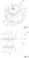
Fig. 5 und Fig. 6 dargestellte Ausführungsvariante der Erfindung zeigt einen Kraft- oder Beschleunigungssensor 40, wobei ein zentrales, beispielsweise T-förmiges Krafteinleitelement 3 als Auflager 12 des Sensors 40 ausgeführt ist und eine Montagefläche 22 zur Befestigung an einem hier nicht weiter dargestellten Bauteil aufweist. Zwei seitlich angeordnete Krafteinleitelemente 3 sind als seismische Massen 21 ausgebildet, wobei zwischen jeder seismischem Masse 21 und dem Auflager 12 jeweils ein Stapel mit piezoelektrischen Elementen 2 angeordnet ist und die jeweils äußeren piezoelektrischen Elemente 2 jedes Stapels unter Zwischenlage eines Übergangselementes 5 am Auflager 12 bzw. an den seismischen Massen 21 anliegen. Die vier Übergangselemente 5 und die dazwischen angeordneten piezoelektrischen Elemente 2 sind beispielsweise ringförmig ausgebildet, um ein am Auflager 12 und den beiden seismischen Massen 21 angreifendes Vorspannelement 23 aufzunehmen. Die Vorrichtung eignet sich beispielsweise zur Erfassung von Scher- und Vibrationskräften, die in der Messrichtung x auftreten und eine Scherbelastung in die Übergangselemente 5 einleiten (sieheFig. 6 ). - Die elektrische Kontaktierung erfolgt über dünne Elektrodenbleche 16 aus einem Folienmaterial.
Claims (14)
- Piezoelektrische Vorrichtung mit zumindest einem piezoelektrischen Element (2), welches eine zu einem Krafteinleitelement (3) ausgerichtete Auflageebene (4) aufweist, wobei bei einer thermischen Belastung der piezoelektrischen Vorrichtung in der Auflageebene (4) Ausdehnungsunterschiede zwischen dem piezoelektrischen Element (2) und dem Krafteinleitelement (3) auftreten, wobei zwischen dem piezoelektrischen Element (2) und dem Krafteinleitelement (3) mindestens ein Übergangselement (5) angeordnet ist, dadurch gekennzeichnet, dass das Übergangselement (5) einen E-Modul aufweist, dessen E-Modul-Komponenten c22, c33 in der Auflageebene (4) jeweils kleiner sind als die entsprechenden E-Modul-Komponenten des piezoelektrischen Elements (2), wobei das Übergangselement (5) in Richtung einer auf das piezoelektrische Element (2) einwirkenden Kraft eine Druckfestigkeit von zumindest 30% der Druckfestigkeit des piezoelektrischen Elements (2) aufweist.
- Piezoelektrische Vorrichtung nach Anspruch 1, dadurch gekennzeichnet, dass das zumindest eine piezoelektrische Element (2) eine anisotrope thermische Ausdehnung und einen durch einen Elastizitätstensor beschreibbaren anisotropen E-Modul aufweist.
- Piezoelektrische Vorrichtung nach Anspruch 1 oder 2, dadurch gekennzeichnet, dass das Übergangselement (5) in Richtung einer auf das piezoelektrische Element (2) einwirkenden Kraft eine Druckfestigkeit von über 90%, der Druckfestigkeit des piezoelektrischen Elements (2) aufweist.
- Piezoelektrische Vorrichtung nach einem der Ansprüche 1 bis 3, dadurch gekennzeichnet, dass das Übergangselement (5) zusammen mit dem piezoelektrischen Element (2) vorgespannt ist, um Scherkräfte aufzunehmen.
- Piezoelektrische Vorrichtung nach einem der Ansprüche 1 bis 4, dadurch gekennzeichnet, dass das Übergangselement (5) großteils, aus gesintertem, hexagonalem Bornitrid besteht.
- Piezoelektrische Vorrichtung nach Anspruch 5, dadurch gekennzeichnet, dass das Übergangselement (5) Anteile an Siliciumcarbid (SiC), Zirconuim(IV)oxid (ZrO2) und/oder Siliciumoxid (SiO2) enthält.
- Piezoelektrische Vorrichtung nach Anspruch 5 oder 6, dadurch gekennzeichnet, dass das Übergangselement (5) als Bindemittel Boroxid enthält.
- Piezoelektrische Vorrichtung nach einem der Ansprüche 2 bis 7, dadurch gekennzeichnet, dass das Übergangselement (5) ein anisotropes E-Modul aufweist, und dahingehend orientiert ist, dass die anisotrope thermische Ausdehnung des piezoelektrischen Elementes (2) in dessen Auflageebene (4) optimal kompensiert ist.
- Piezoelektrische Vorrichtung nach einem der Ansprüche 1 bis 8, dadurch gekennzeichnet, dass piezoelektrischen Element (2) aus GaPO4, Langasit, Langatat oder Turmalin besteht.
- Piezoelektrische Vorrichtung nach einem der Ansprüche 1 bis 8, dadurch gekennzeichnet, dass piezoelektrischen Element (2) aus einer Piezokeramik, beispielsweise aus Bismuthtitanat besteht.
- Piezoelektrische Vorrichtung nach einem der Ansprüche 1 bis 10, dadurch gekennzeichnet, dass die piezoelektrische Vorrichtung dazu ausgebildet ist den longitudinalen Piezoeffekt des piezoelektrischen Elements (2) zur Bestimmung einer Größe zu verwenden, wobei die Dicke des Übergangselements (5) zwischen 20% und 500%, vorzugsweise zwischen 50% und 300%, der Dicke des in einem Stapel angeordneten piezoelektrischen Elements (2) beträgt.
- Piezoelektrische Vorrichtung nach einem der Ansprüche 1 bis 10, dadurch gekennzeichnet, dass die piezoelektrische Vorrichtung dazu ausgebildet ist den transversalen Piezoeffekt des piezoelektrischen Elements (2) zur Bestimmung einer Größe zu verwenden, wobei die Dicke des Übergangselements (5) zwischen 5% und 200%, vorzugsweise zwischen 10% und 50%, der Höhe des stehend angeordneten piezoelektrischen Elements (2) beträgt.
- Piezoelektrische Vorrichtung nach einem der Ansprüche 1 bis 12, dadurch gekennzeichnet, dass zur Realisierung eines Drucksensors (10) mit einer Sensormembran (11) ein Krafteinleitelement (3) als Auflager (12) des Drucksensors und ein Krafteinleitelement (3) als von der Sensormembran (11) beaufschlagtes Druckstück (14) ausgebildet ist, wobei zwischen dem Auflager (12) und dem piezoelektrischen Element (2) ein erstes Übergangselement (5) und zwischen dem piezoelektrischen Element (2) und dem Druckstück (14) ein zweites Übergangselement (5) angeordnet ist.
- Piezoelektrische Vorrichtung nach einem der Ansprüche 1 bis 11, dadurch gekennzeichnet, dass zur Realisierung eines Kraft- oder Beschleunigungssensors (20) ein Krafteinleitelement (3) als Auflager (12) des Kraft- oder Beschleunigungssensors und ein Krafteinleitelement (3) als seismische Masse (21) ausgebildet ist, wobei zwischen dem Auflager (12) und dem piezoelektrischen Element (2) ein erstes Übergangselement (5) und zwischen dem piezoelektrischen Element (2) und der seismischen Masse (21) ein zweites Übergangselement (5) angeordnet ist.
Applications Claiming Priority (2)
| Application Number | Priority Date | Filing Date | Title |
|---|---|---|---|
| ATA50656/2017A AT520086B1 (de) | 2017-08-07 | 2017-08-07 | Piezoelektrische vorrichtung mit zumindest einem piezoelektrischen element |
| PCT/AT2018/060182 WO2019028488A1 (de) | 2017-08-07 | 2018-08-07 | Piezoelektrische vorrichtung mit zumindest einem piezoelektrischen element |
Publications (3)
| Publication Number | Publication Date |
|---|---|
| EP3665459A1 EP3665459A1 (de) | 2020-06-17 |
| EP3665459B1 EP3665459B1 (de) | 2022-01-12 |
| EP3665459B2 true EP3665459B2 (de) | 2025-03-26 |
Family
ID=63363802
Family Applications (1)
| Application Number | Title | Priority Date | Filing Date |
|---|---|---|---|
| EP18759239.9A Active EP3665459B2 (de) | 2017-08-07 | 2018-08-07 | Piezoelektrische vorrichtung mit zumindest einem piezoelektrischen element |
Country Status (4)
| Country | Link |
|---|---|
| US (1) | US11994437B2 (de) |
| EP (1) | EP3665459B2 (de) |
| AT (1) | AT520086B1 (de) |
| WO (1) | WO2019028488A1 (de) |
Families Citing this family (1)
| Publication number | Priority date | Publication date | Assignee | Title |
|---|---|---|---|---|
| EP4325189A1 (de) | 2022-08-19 | 2024-02-21 | Meggitt SA | Piezoelektrische sensorvorrichtung |
Citations (3)
| Publication number | Priority date | Publication date | Assignee | Title |
|---|---|---|---|---|
| DE3824849A1 (de) † | 1988-07-21 | 1990-01-25 | Kempten Elektroschmelz Gmbh | Unter druck gesinterte, polykristalline mischwerkstoffe auf basis von hexagonalem bornitrid, oxiden und carbiden |
| JP2013174553A (ja) † | 2012-02-27 | 2013-09-05 | Citizen Finetech Miyota Co Ltd | 圧力検出装置、圧力検出装置付き内燃機関 |
| CN104817326A (zh) † | 2015-04-13 | 2015-08-05 | 中国科学院金属研究所 | 一种六方氮化硼-镱硅氧-二氧化硅复合材料及制备方法 |
Family Cites Families (17)
| Publication number | Priority date | Publication date | Assignee | Title |
|---|---|---|---|---|
| US2988728A (en) * | 1953-07-06 | 1961-06-13 | United Geophysical Corp | Piezoelectric hydrophone |
| US3727084A (en) * | 1970-06-29 | 1973-04-10 | Becton Dickinson Co | Accelerometer utilizing shear responsive x-cut lithium niobate |
| AT371255B (de) * | 1972-11-08 | 1983-06-10 | Becton Dickinson Co | Beschleunigungsaufnehmer |
| US4052628A (en) | 1976-04-19 | 1977-10-04 | Gulton Industries, Inc. | Dynamic, shear-mode piezoelectric pressure sensor |
| FR2448721A1 (fr) * | 1979-02-09 | 1980-09-05 | Cartier Jean | Accelerometre piezoelectrique |
| JPS59216028A (ja) * | 1983-05-24 | 1984-12-06 | Junji Isoyama | 内燃機関用指圧器 |
| CH670310A5 (de) * | 1985-04-17 | 1989-05-31 | Kristal Instr Ag | |
| EP0270693B1 (de) * | 1986-11-07 | 1991-07-17 | Kristal Instrumente AG | Mehrkomponenten-Dynamometer |
| AT403959B (de) * | 1995-12-15 | 1998-07-27 | Avl Verbrennungskraft Messtech | Messanordnung mit einem piezoelektrischen, anisotropen messelement |
| DE10023556A1 (de) * | 2000-05-15 | 2001-11-29 | Festo Ag & Co | Piezo-Biegewandler sowie Verwendung desselben |
| AT409550B (de) * | 2001-04-23 | 2002-09-25 | Avl List Gmbh | Piezoelektrische vorrichtung |
| JP2008196874A (ja) * | 2007-02-09 | 2008-08-28 | Matsushita Electric Ind Co Ltd | 圧力検出素子 |
| AT506705B1 (de) * | 2008-09-11 | 2009-11-15 | Piezocryst Advanced Sensorics | Piezoelektrischer drucksensor |
| US8375793B2 (en) * | 2011-02-10 | 2013-02-19 | Dytran Instruments, Inc. | Accelerometer for high temperature applications |
| DE102012005555B3 (de) * | 2012-03-21 | 2013-08-22 | Audi Ag | Messplatte mit Sensoren |
| JP5689523B1 (ja) * | 2013-12-18 | 2015-03-25 | 日本写真印刷株式会社 | 圧力検出器を備えたタッチパネル |
| DE102020206480A1 (de) * | 2020-05-25 | 2021-11-25 | Aktiebolaget Skf | Piezoelektrische Dehnungssensoreinheit für ein Wälzlager |
-
2017
- 2017-08-07 AT ATA50656/2017A patent/AT520086B1/de active
-
2018
- 2018-08-07 EP EP18759239.9A patent/EP3665459B2/de active Active
- 2018-08-07 WO PCT/AT2018/060182 patent/WO2019028488A1/de not_active Ceased
- 2018-08-07 US US16/637,336 patent/US11994437B2/en active Active
Patent Citations (3)
| Publication number | Priority date | Publication date | Assignee | Title |
|---|---|---|---|---|
| DE3824849A1 (de) † | 1988-07-21 | 1990-01-25 | Kempten Elektroschmelz Gmbh | Unter druck gesinterte, polykristalline mischwerkstoffe auf basis von hexagonalem bornitrid, oxiden und carbiden |
| JP2013174553A (ja) † | 2012-02-27 | 2013-09-05 | Citizen Finetech Miyota Co Ltd | 圧力検出装置、圧力検出装置付き内燃機関 |
| CN104817326A (zh) † | 2015-04-13 | 2015-08-05 | 中国科学院金属研究所 | 一种六方氮化硼-镱硅氧-二氧化硅复合材料及制备方法 |
Non-Patent Citations (4)
| Title |
|---|
| "Piezoelectric Sensorics", 1 January 2002, SPRINGER, article GAUTSCHI GUSTAV: "Chaters 1, 2 and 3", pages: 1 - 38 † |
| "Taschenbuch der Physik", 1 January 1990, CARL VERLAG, article KUCHLING HORST: "Tabelle 9", pages: 26 - 27, 614-615 † |
| ANONYMOUS: "Infomaterial", METALLGUSS MERTENS USINGEN, 7 February 2016 (2016-02-07), pages 1 - 33, Retrieved from the Internet <URL:http://www.alu-guss.de/Metallguss_Mertens_Usingen_Infomaterial.pdf> [retrieved on 20221024] † |
| ANONYMOUS: "Silica - Silicon Dioxide (SiO2)", AZO MATERIALS, 13 December 2001 (2001-12-13), Retrieved from the Internet <URL:https://www.azom.com/properties.aspx?ArticleID=1114> [retrieved on 20221024] † |
Also Published As
| Publication number | Publication date |
|---|---|
| US20230194368A1 (en) | 2023-06-22 |
| US11994437B2 (en) | 2024-05-28 |
| AT520086B1 (de) | 2019-01-15 |
| EP3665459A1 (de) | 2020-06-17 |
| AT520086A4 (de) | 2019-01-15 |
| WO2019028488A1 (de) | 2019-02-14 |
| EP3665459B1 (de) | 2022-01-12 |
Similar Documents
| Publication | Publication Date | Title |
|---|---|---|
| DE69308512T2 (de) | Piezoelektrischer Antrieb mit Dehnungsmesser | |
| DE102006019942B4 (de) | Kraftmessvorrichtung zur Messung der Kraft bei Festkörperaktoren, Verfahren zur Messung einer Kraft sowie Verwendung der Kraftmessvorrichtung | |
| EP0140992B1 (de) | Wandlerelement, Verfahren zu seiner Herstellung sowie Verwendung für einen Druckaufnehmer | |
| EP3237868B1 (de) | Druckmesseinrichtung | |
| EP2812991B1 (de) | Ultraschallaktor | |
| EP2436051B1 (de) | Piezoelektrisches bauelement | |
| EP1876434A2 (de) | Vorrichtung zum Messen von Kräften, insbesondere Drucksensor, und zugehöriges Herstellverfahren | |
| EP1797603B1 (de) | Sensorelement mit zumindest einem messelement, welches piezoelektrische und pyroelektrische eigenschaften aufweist | |
| EP3665459B2 (de) | Piezoelektrische vorrichtung mit zumindest einem piezoelektrischen element | |
| DE60313552T2 (de) | Verfahren zur Herstellung eines Dehnungsmesssensors | |
| DE102018108743A1 (de) | Drucksensor | |
| DE69904091T2 (de) | Hochempfindlicher Sensor zur Erfassung einer mechanischen Grösse | |
| DE102019132021B4 (de) | Vibrationssensor mit integrierter Temperaturerfassung mit einer in Schwingung versetzbaren Membran | |
| EP2789966A1 (de) | Dehnungsmesssensor | |
| DE102006023724B4 (de) | Messzellenanordnung für einen Drucksensor mit Kraftmesselement aus Glas | |
| EP1263060A2 (de) | Verfahren zur Herstellung eines flachen mehrschichtigen Bauelementes sowie entsprechendes Bauelement | |
| DE3888118T2 (de) | Drucksensoren und Methode zum Messen des Drucks. | |
| WO2011092205A1 (de) | Piezoelektrisches bauelement | |
| DE112022000089T5 (de) | Element zur erzeugung elektrischer energie aus vibration | |
| EP3642583A1 (de) | Schichtwiderstand und dünnfilmsensor | |
| DE102012204853A1 (de) | Verfahren zum Herstellen einer Dünnschicht auf einem Substrat | |
| DE102010051049B4 (de) | Piezoresistives Druckmesselement und Verwendung des Druckmesselements | |
| DE1573628A1 (de) | Temperatur- und beschleunigungskompensierter piezoelektrischer Messwandler | |
| DE10206977B4 (de) | Verfahren zur Herstellung eines mehrschichtigen Bauelements sowie danach hergestelltes Bauelement | |
| DE2332764A1 (de) | Temperaturkompensation fuer einen messwertgeber |
Legal Events
| Date | Code | Title | Description |
|---|---|---|---|
| STAA | Information on the status of an ep patent application or granted ep patent |
Free format text: STATUS: UNKNOWN |
|
| STAA | Information on the status of an ep patent application or granted ep patent |
Free format text: STATUS: THE INTERNATIONAL PUBLICATION HAS BEEN MADE |
|
| PUAI | Public reference made under article 153(3) epc to a published international application that has entered the european phase |
Free format text: ORIGINAL CODE: 0009012 |
|
| STAA | Information on the status of an ep patent application or granted ep patent |
Free format text: STATUS: REQUEST FOR EXAMINATION WAS MADE |
|
| 17P | Request for examination filed |
Effective date: 20200304 |
|
| AK | Designated contracting states |
Kind code of ref document: A1 Designated state(s): AL AT BE BG CH CY CZ DE DK EE ES FI FR GB GR HR HU IE IS IT LI LT LU LV MC MK MT NL NO PL PT RO RS SE SI SK SM TR |
|
| AX | Request for extension of the european patent |
Extension state: BA ME |
|
| DAV | Request for validation of the european patent (deleted) | ||
| DAX | Request for extension of the european patent (deleted) | ||
| STAA | Information on the status of an ep patent application or granted ep patent |
Free format text: STATUS: EXAMINATION IS IN PROGRESS |
|
| 17Q | First examination report despatched |
Effective date: 20210517 |
|
| GRAP | Despatch of communication of intention to grant a patent |
Free format text: ORIGINAL CODE: EPIDOSNIGR1 |
|
| STAA | Information on the status of an ep patent application or granted ep patent |
Free format text: STATUS: GRANT OF PATENT IS INTENDED |
|
| INTG | Intention to grant announced |
Effective date: 20211026 |
|
| GRAS | Grant fee paid |
Free format text: ORIGINAL CODE: EPIDOSNIGR3 |
|
| GRAA | (expected) grant |
Free format text: ORIGINAL CODE: 0009210 |
|
| STAA | Information on the status of an ep patent application or granted ep patent |
Free format text: STATUS: THE PATENT HAS BEEN GRANTED |
|
| AK | Designated contracting states |
Kind code of ref document: B1 Designated state(s): AL AT BE BG CH CY CZ DE DK EE ES FI FR GB GR HR HU IE IS IT LI LT LU LV MC MK MT NL NO PL PT RO RS SE SI SK SM TR |
|
| REG | Reference to a national code |
Ref country code: GB Ref legal event code: FG4D Free format text: NOT ENGLISH |
|
| REG | Reference to a national code |
Ref country code: CH Ref legal event code: EP |
|
| REG | Reference to a national code |
Ref country code: DE Ref legal event code: R096 Ref document number: 502018008518 Country of ref document: DE |
|
| REG | Reference to a national code |
Ref country code: IE Ref legal event code: FG4D Free format text: LANGUAGE OF EP DOCUMENT: GERMAN |
|
| REG | Reference to a national code |
Ref country code: AT Ref legal event code: REF Ref document number: 1462693 Country of ref document: AT Kind code of ref document: T Effective date: 20220215 |
|
| REG | Reference to a national code |
Ref country code: LT Ref legal event code: MG9D |
|
| REG | Reference to a national code |
Ref country code: NL Ref legal event code: MP Effective date: 20220112 |
|
| PG25 | Lapsed in a contracting state [announced via postgrant information from national office to epo] |
Ref country code: NL Free format text: LAPSE BECAUSE OF FAILURE TO SUBMIT A TRANSLATION OF THE DESCRIPTION OR TO PAY THE FEE WITHIN THE PRESCRIBED TIME-LIMIT Effective date: 20220112 |
|
| PG25 | Lapsed in a contracting state [announced via postgrant information from national office to epo] |
Ref country code: SE Free format text: LAPSE BECAUSE OF FAILURE TO SUBMIT A TRANSLATION OF THE DESCRIPTION OR TO PAY THE FEE WITHIN THE PRESCRIBED TIME-LIMIT Effective date: 20220112 Ref country code: RS Free format text: LAPSE BECAUSE OF FAILURE TO SUBMIT A TRANSLATION OF THE DESCRIPTION OR TO PAY THE FEE WITHIN THE PRESCRIBED TIME-LIMIT Effective date: 20220112 Ref country code: PT Free format text: LAPSE BECAUSE OF FAILURE TO SUBMIT A TRANSLATION OF THE DESCRIPTION OR TO PAY THE FEE WITHIN THE PRESCRIBED TIME-LIMIT Effective date: 20220512 Ref country code: NO Free format text: LAPSE BECAUSE OF FAILURE TO SUBMIT A TRANSLATION OF THE DESCRIPTION OR TO PAY THE FEE WITHIN THE PRESCRIBED TIME-LIMIT Effective date: 20220412 Ref country code: LT Free format text: LAPSE BECAUSE OF FAILURE TO SUBMIT A TRANSLATION OF THE DESCRIPTION OR TO PAY THE FEE WITHIN THE PRESCRIBED TIME-LIMIT Effective date: 20220112 Ref country code: HR Free format text: LAPSE BECAUSE OF FAILURE TO SUBMIT A TRANSLATION OF THE DESCRIPTION OR TO PAY THE FEE WITHIN THE PRESCRIBED TIME-LIMIT Effective date: 20220112 Ref country code: ES Free format text: LAPSE BECAUSE OF FAILURE TO SUBMIT A TRANSLATION OF THE DESCRIPTION OR TO PAY THE FEE WITHIN THE PRESCRIBED TIME-LIMIT Effective date: 20220112 Ref country code: BG Free format text: LAPSE BECAUSE OF FAILURE TO SUBMIT A TRANSLATION OF THE DESCRIPTION OR TO PAY THE FEE WITHIN THE PRESCRIBED TIME-LIMIT Effective date: 20220412 |
|
| PG25 | Lapsed in a contracting state [announced via postgrant information from national office to epo] |
Ref country code: PL Free format text: LAPSE BECAUSE OF FAILURE TO SUBMIT A TRANSLATION OF THE DESCRIPTION OR TO PAY THE FEE WITHIN THE PRESCRIBED TIME-LIMIT Effective date: 20220112 Ref country code: LV Free format text: LAPSE BECAUSE OF FAILURE TO SUBMIT A TRANSLATION OF THE DESCRIPTION OR TO PAY THE FEE WITHIN THE PRESCRIBED TIME-LIMIT Effective date: 20220112 Ref country code: GR Free format text: LAPSE BECAUSE OF FAILURE TO SUBMIT A TRANSLATION OF THE DESCRIPTION OR TO PAY THE FEE WITHIN THE PRESCRIBED TIME-LIMIT Effective date: 20220413 Ref country code: FI Free format text: LAPSE BECAUSE OF FAILURE TO SUBMIT A TRANSLATION OF THE DESCRIPTION OR TO PAY THE FEE WITHIN THE PRESCRIBED TIME-LIMIT Effective date: 20220112 |
|
| PG25 | Lapsed in a contracting state [announced via postgrant information from national office to epo] |
Ref country code: IS Free format text: LAPSE BECAUSE OF FAILURE TO SUBMIT A TRANSLATION OF THE DESCRIPTION OR TO PAY THE FEE WITHIN THE PRESCRIBED TIME-LIMIT Effective date: 20220512 |
|
| REG | Reference to a national code |
Ref country code: DE Ref legal event code: R026 Ref document number: 502018008518 Country of ref document: DE |
|
| PLBI | Opposition filed |
Free format text: ORIGINAL CODE: 0009260 |
|
| PLAX | Notice of opposition and request to file observation + time limit sent |
Free format text: ORIGINAL CODE: EPIDOSNOBS2 |
|
| PG25 | Lapsed in a contracting state [announced via postgrant information from national office to epo] |
Ref country code: SM Free format text: LAPSE BECAUSE OF FAILURE TO SUBMIT A TRANSLATION OF THE DESCRIPTION OR TO PAY THE FEE WITHIN THE PRESCRIBED TIME-LIMIT Effective date: 20220112 Ref country code: SK Free format text: LAPSE BECAUSE OF FAILURE TO SUBMIT A TRANSLATION OF THE DESCRIPTION OR TO PAY THE FEE WITHIN THE PRESCRIBED TIME-LIMIT Effective date: 20220112 Ref country code: RO Free format text: LAPSE BECAUSE OF FAILURE TO SUBMIT A TRANSLATION OF THE DESCRIPTION OR TO PAY THE FEE WITHIN THE PRESCRIBED TIME-LIMIT Effective date: 20220112 Ref country code: EE Free format text: LAPSE BECAUSE OF FAILURE TO SUBMIT A TRANSLATION OF THE DESCRIPTION OR TO PAY THE FEE WITHIN THE PRESCRIBED TIME-LIMIT Effective date: 20220112 Ref country code: DK Free format text: LAPSE BECAUSE OF FAILURE TO SUBMIT A TRANSLATION OF THE DESCRIPTION OR TO PAY THE FEE WITHIN THE PRESCRIBED TIME-LIMIT Effective date: 20220112 Ref country code: CZ Free format text: LAPSE BECAUSE OF FAILURE TO SUBMIT A TRANSLATION OF THE DESCRIPTION OR TO PAY THE FEE WITHIN THE PRESCRIBED TIME-LIMIT Effective date: 20220112 |
|
| 26 | Opposition filed |
Opponent name: KISTLER INSTRUMENTE AG Effective date: 20221011 |
|
| PG25 | Lapsed in a contracting state [announced via postgrant information from national office to epo] |
Ref country code: AL Free format text: LAPSE BECAUSE OF FAILURE TO SUBMIT A TRANSLATION OF THE DESCRIPTION OR TO PAY THE FEE WITHIN THE PRESCRIBED TIME-LIMIT Effective date: 20220112 |
|
| PG25 | Lapsed in a contracting state [announced via postgrant information from national office to epo] |
Ref country code: SI Free format text: LAPSE BECAUSE OF FAILURE TO SUBMIT A TRANSLATION OF THE DESCRIPTION OR TO PAY THE FEE WITHIN THE PRESCRIBED TIME-LIMIT Effective date: 20220112 |
|
| PLBB | Reply of patent proprietor to notice(s) of opposition received |
Free format text: ORIGINAL CODE: EPIDOSNOBS3 |
|
| PG25 | Lapsed in a contracting state [announced via postgrant information from national office to epo] |
Ref country code: MC Free format text: LAPSE BECAUSE OF FAILURE TO SUBMIT A TRANSLATION OF THE DESCRIPTION OR TO PAY THE FEE WITHIN THE PRESCRIBED TIME-LIMIT Effective date: 20220112 |
|
| GBPC | Gb: european patent ceased through non-payment of renewal fee |
Effective date: 20220807 |
|
| PG25 | Lapsed in a contracting state [announced via postgrant information from national office to epo] |
Ref country code: LU Free format text: LAPSE BECAUSE OF NON-PAYMENT OF DUE FEES Effective date: 20220807 |
|
| REG | Reference to a national code |
Ref country code: BE Ref legal event code: MM Effective date: 20220831 |
|
| P01 | Opt-out of the competence of the unified patent court (upc) registered |
Effective date: 20230502 |
|
| PG25 | Lapsed in a contracting state [announced via postgrant information from national office to epo] |
Ref country code: IT Free format text: LAPSE BECAUSE OF FAILURE TO SUBMIT A TRANSLATION OF THE DESCRIPTION OR TO PAY THE FEE WITHIN THE PRESCRIBED TIME-LIMIT Effective date: 20220112 Ref country code: IE Free format text: LAPSE BECAUSE OF NON-PAYMENT OF DUE FEES Effective date: 20220807 Ref country code: FR Free format text: LAPSE BECAUSE OF NON-PAYMENT OF DUE FEES Effective date: 20220831 |
|
| PG25 | Lapsed in a contracting state [announced via postgrant information from national office to epo] |
Ref country code: BE Free format text: LAPSE BECAUSE OF NON-PAYMENT OF DUE FEES Effective date: 20220831 |
|
| PG25 | Lapsed in a contracting state [announced via postgrant information from national office to epo] |
Ref country code: GB Free format text: LAPSE BECAUSE OF NON-PAYMENT OF DUE FEES Effective date: 20220807 |
|
| PG25 | Lapsed in a contracting state [announced via postgrant information from national office to epo] |
Ref country code: CY Free format text: LAPSE BECAUSE OF FAILURE TO SUBMIT A TRANSLATION OF THE DESCRIPTION OR TO PAY THE FEE WITHIN THE PRESCRIBED TIME-LIMIT Effective date: 20220112 |
|
| PG25 | Lapsed in a contracting state [announced via postgrant information from national office to epo] |
Ref country code: MK Free format text: LAPSE BECAUSE OF FAILURE TO SUBMIT A TRANSLATION OF THE DESCRIPTION OR TO PAY THE FEE WITHIN THE PRESCRIBED TIME-LIMIT Effective date: 20220112 Ref country code: HU Free format text: LAPSE BECAUSE OF FAILURE TO SUBMIT A TRANSLATION OF THE DESCRIPTION OR TO PAY THE FEE WITHIN THE PRESCRIBED TIME-LIMIT; INVALID AB INITIO Effective date: 20180807 |
|
| PG25 | Lapsed in a contracting state [announced via postgrant information from national office to epo] |
Ref country code: TR Free format text: LAPSE BECAUSE OF FAILURE TO SUBMIT A TRANSLATION OF THE DESCRIPTION OR TO PAY THE FEE WITHIN THE PRESCRIBED TIME-LIMIT Effective date: 20220112 |
|
| PG25 | Lapsed in a contracting state [announced via postgrant information from national office to epo] |
Ref country code: MT Free format text: LAPSE BECAUSE OF FAILURE TO SUBMIT A TRANSLATION OF THE DESCRIPTION OR TO PAY THE FEE WITHIN THE PRESCRIBED TIME-LIMIT Effective date: 20220112 |
|
| REG | Reference to a national code |
Ref country code: AT Ref legal event code: MM01 Ref document number: 1462693 Country of ref document: AT Kind code of ref document: T Effective date: 20230807 |
|
| PG25 | Lapsed in a contracting state [announced via postgrant information from national office to epo] |
Ref country code: AT Free format text: LAPSE BECAUSE OF NON-PAYMENT OF DUE FEES Effective date: 20230807 |
|
| PG25 | Lapsed in a contracting state [announced via postgrant information from national office to epo] |
Ref country code: AT Free format text: LAPSE BECAUSE OF NON-PAYMENT OF DUE FEES Effective date: 20230807 |
|
| PUAH | Patent maintained in amended form |
Free format text: ORIGINAL CODE: 0009272 |
|
| STAA | Information on the status of an ep patent application or granted ep patent |
Free format text: STATUS: PATENT MAINTAINED AS AMENDED |
|
| 27A | Patent maintained in amended form |
Effective date: 20250326 |
|
| AK | Designated contracting states |
Kind code of ref document: B2 Designated state(s): AL AT BE BG CH CY CZ DE DK EE ES FI FR GB GR HR HU IE IS IT LI LT LU LV MC MK MT NL NO PL PT RO RS SE SI SK SM TR |
|
| REG | Reference to a national code |
Ref country code: DE Ref legal event code: R102 Ref document number: 502018008518 Country of ref document: DE |
|
| PGFP | Annual fee paid to national office [announced via postgrant information from national office to epo] |
Ref country code: DE Payment date: 20250724 Year of fee payment: 8 |
|
| PGFP | Annual fee paid to national office [announced via postgrant information from national office to epo] |
Ref country code: CH Payment date: 20250901 Year of fee payment: 8 |
|
| PGFP | Annual fee paid to national office [announced via postgrant information from national office to epo] |
Ref country code: AT Payment date: 20260410 Year of fee payment: 5 |