EP3665131B1 - Particle mixture - Google Patents
Particle mixture Download PDFInfo
- Publication number
- EP3665131B1 EP3665131B1 EP18745700.7A EP18745700A EP3665131B1 EP 3665131 B1 EP3665131 B1 EP 3665131B1 EP 18745700 A EP18745700 A EP 18745700A EP 3665131 B1 EP3665131 B1 EP 3665131B1
- Authority
- EP
- European Patent Office
- Prior art keywords
- less
- glass frit
- glass
- particle mixture
- particles
- Prior art date
- Legal status (The legal status is an assumption and is not a legal conclusion. Google has not performed a legal analysis and makes no representation as to the accuracy of the status listed.)
- Active
Links
- 239000002245 particle Substances 0.000 title claims description 191
- 239000000203 mixture Substances 0.000 title claims description 99
- 239000011521 glass Substances 0.000 claims description 227
- 210000003298 dental enamel Anatomy 0.000 claims description 84
- 239000000758 substrate Substances 0.000 claims description 58
- 239000000463 material Substances 0.000 claims description 57
- 239000000049 pigment Substances 0.000 claims description 35
- 239000007788 liquid Substances 0.000 claims description 28
- XLOMVQKBTHCTTD-UHFFFAOYSA-N Zinc monoxide Chemical compound [Zn]=O XLOMVQKBTHCTTD-UHFFFAOYSA-N 0.000 claims description 24
- WMWLMWRWZQELOS-UHFFFAOYSA-N bismuth(iii) oxide Chemical compound O=[Bi]O[Bi]=O WMWLMWRWZQELOS-UHFFFAOYSA-N 0.000 claims description 22
- 239000002612 dispersion medium Substances 0.000 claims description 22
- VYPSYNLAJGMNEJ-UHFFFAOYSA-N Silicium dioxide Chemical compound O=[Si]=O VYPSYNLAJGMNEJ-UHFFFAOYSA-N 0.000 claims description 20
- 229910052814 silicon oxide Inorganic materials 0.000 claims description 20
- GWEVSGVZZGPLCZ-UHFFFAOYSA-N Titan oxide Chemical compound O=[Ti]=O GWEVSGVZZGPLCZ-UHFFFAOYSA-N 0.000 claims description 19
- JKWMSGQKBLHBQQ-UHFFFAOYSA-N diboron trioxide Chemical compound O=BOB=O JKWMSGQKBLHBQQ-UHFFFAOYSA-N 0.000 claims description 14
- 229910011255 B2O3 Inorganic materials 0.000 claims description 13
- ZKATWMILCYLAPD-UHFFFAOYSA-N niobium pentoxide Chemical compound O=[Nb](=O)O[Nb](=O)=O ZKATWMILCYLAPD-UHFFFAOYSA-N 0.000 claims description 12
- FUJCRWPEOMXPAD-UHFFFAOYSA-N Li2O Inorganic materials [Li+].[Li+].[O-2] FUJCRWPEOMXPAD-UHFFFAOYSA-N 0.000 claims description 10
- KKCBUQHMOMHUOY-UHFFFAOYSA-N Na2O Inorganic materials [O-2].[Na+].[Na+] KKCBUQHMOMHUOY-UHFFFAOYSA-N 0.000 claims description 10
- XUCJHNOBJLKZNU-UHFFFAOYSA-M dilithium;hydroxide Chemical compound [Li+].[Li+].[OH-] XUCJHNOBJLKZNU-UHFFFAOYSA-M 0.000 claims description 10
- 229910052717 sulfur Inorganic materials 0.000 claims description 9
- 229910052844 willemite Inorganic materials 0.000 claims description 9
- 239000011787 zinc oxide Substances 0.000 claims description 9
- XEEYBQQBJWHFJM-UHFFFAOYSA-N Iron Chemical compound [Fe] XEEYBQQBJWHFJM-UHFFFAOYSA-N 0.000 claims description 8
- -1 5ZnO.2B2O3 Inorganic materials 0.000 claims description 7
- 229910000421 cerium(III) oxide Inorganic materials 0.000 claims description 7
- NINIDFKCEFEMDL-UHFFFAOYSA-N Sulfur Chemical compound [S] NINIDFKCEFEMDL-UHFFFAOYSA-N 0.000 claims description 6
- 239000011593 sulfur Substances 0.000 claims description 6
- PXHVJJICTQNCMI-UHFFFAOYSA-N Nickel Chemical compound [Ni] PXHVJJICTQNCMI-UHFFFAOYSA-N 0.000 claims description 4
- 229910052804 chromium Inorganic materials 0.000 claims description 4
- 239000011651 chromium Substances 0.000 claims description 4
- 229910052742 iron Inorganic materials 0.000 claims description 4
- 235000019352 zinc silicate Nutrition 0.000 claims description 3
- VYZAMTAEIAYCRO-UHFFFAOYSA-N Chromium Chemical compound [Cr] VYZAMTAEIAYCRO-UHFFFAOYSA-N 0.000 claims description 2
- RYGMFSIKBFXOCR-UHFFFAOYSA-N Copper Chemical compound [Cu] RYGMFSIKBFXOCR-UHFFFAOYSA-N 0.000 claims description 2
- 229910002477 CuCr2O4 Inorganic materials 0.000 claims description 2
- XUIMIQQOPSSXEZ-UHFFFAOYSA-N Silicon Chemical compound [Si] XUIMIQQOPSSXEZ-UHFFFAOYSA-N 0.000 claims description 2
- 229910000323 aluminium silicate Inorganic materials 0.000 claims description 2
- 235000012211 aluminium silicate Nutrition 0.000 claims description 2
- 229910052849 andalusite Inorganic materials 0.000 claims description 2
- 235000012215 calcium aluminium silicate Nutrition 0.000 claims description 2
- 229910001598 chiastolite Inorganic materials 0.000 claims description 2
- 229910017052 cobalt Inorganic materials 0.000 claims description 2
- 239000010941 cobalt Substances 0.000 claims description 2
- GUTLYIVDDKVIGB-UHFFFAOYSA-N cobalt atom Chemical compound [Co] GUTLYIVDDKVIGB-UHFFFAOYSA-N 0.000 claims description 2
- 229910052802 copper Inorganic materials 0.000 claims description 2
- 239000010949 copper Substances 0.000 claims description 2
- 229910052850 kyanite Inorganic materials 0.000 claims description 2
- WPBNNNQJVZRUHP-UHFFFAOYSA-L manganese(2+);methyl n-[[2-(methoxycarbonylcarbamothioylamino)phenyl]carbamothioyl]carbamate;n-[2-(sulfidocarbothioylamino)ethyl]carbamodithioate Chemical compound [Mn+2].[S-]C(=S)NCCNC([S-])=S.COC(=O)NC(=S)NC1=CC=CC=C1NC(=S)NC(=O)OC WPBNNNQJVZRUHP-UHFFFAOYSA-L 0.000 claims description 2
- 229910052759 nickel Inorganic materials 0.000 claims description 2
- FULFYAFFAGNFJM-UHFFFAOYSA-N oxocopper;oxo(oxochromiooxy)chromium Chemical group [Cu]=O.O=[Cr]O[Cr]=O FULFYAFFAGNFJM-UHFFFAOYSA-N 0.000 claims description 2
- 229910052710 silicon Inorganic materials 0.000 claims description 2
- 239000010703 silicon Substances 0.000 claims description 2
- LIVNPJMFVYWSIS-UHFFFAOYSA-N silicon monoxide Chemical class [Si-]#[O+] LIVNPJMFVYWSIS-UHFFFAOYSA-N 0.000 claims description 2
- 229910052851 sillimanite Inorganic materials 0.000 claims description 2
- 229910000314 transition metal oxide Inorganic materials 0.000 claims description 2
- BIKXLKXABVUSMH-UHFFFAOYSA-N trizinc;diborate Chemical class [Zn+2].[Zn+2].[Zn+2].[O-]B([O-])[O-].[O-]B([O-])[O-] BIKXLKXABVUSMH-UHFFFAOYSA-N 0.000 claims description 2
- 235000014692 zinc oxide Nutrition 0.000 claims description 2
- RNWHGQJWIACOKP-UHFFFAOYSA-N zinc;oxygen(2-) Chemical class [O-2].[Zn+2] RNWHGQJWIACOKP-UHFFFAOYSA-N 0.000 claims description 2
- 239000000976 ink Substances 0.000 description 83
- 238000000576 coating method Methods 0.000 description 40
- 238000000034 method Methods 0.000 description 38
- 239000011248 coating agent Substances 0.000 description 36
- 238000010304 firing Methods 0.000 description 27
- 239000000725 suspension Substances 0.000 description 20
- 230000003287 optical effect Effects 0.000 description 19
- 238000001035 drying Methods 0.000 description 10
- KFZMGEQAYNKOFK-UHFFFAOYSA-N Isopropanol Chemical compound CC(C)O KFZMGEQAYNKOFK-UHFFFAOYSA-N 0.000 description 9
- 238000010438 heat treatment Methods 0.000 description 9
- 239000010410 layer Substances 0.000 description 9
- 238000002156 mixing Methods 0.000 description 9
- NOTVAPJNGZMVSD-UHFFFAOYSA-N potassium monoxide Inorganic materials [K]O[K] NOTVAPJNGZMVSD-UHFFFAOYSA-N 0.000 description 9
- 238000010296 bead milling Methods 0.000 description 8
- 238000005452 bending Methods 0.000 description 8
- 238000007650 screen-printing Methods 0.000 description 8
- 239000002904 solvent Substances 0.000 description 8
- PNEYBMLMFCGWSK-UHFFFAOYSA-N Alumina Chemical compound [O-2].[O-2].[O-2].[Al+3].[Al+3] PNEYBMLMFCGWSK-UHFFFAOYSA-N 0.000 description 7
- 238000007641 inkjet printing Methods 0.000 description 7
- 229920005989 resin Polymers 0.000 description 7
- 239000011347 resin Substances 0.000 description 7
- 239000007858 starting material Substances 0.000 description 7
- 230000003746 surface roughness Effects 0.000 description 7
- 238000000879 optical micrograph Methods 0.000 description 6
- 230000005855 radiation Effects 0.000 description 6
- 238000007761 roller coating Methods 0.000 description 6
- VHUUQVKOLVNVRT-UHFFFAOYSA-N Ammonium hydroxide Chemical compound [NH4+].[OH-] VHUUQVKOLVNVRT-UHFFFAOYSA-N 0.000 description 5
- 229910052797 bismuth Inorganic materials 0.000 description 5
- JCXGWMGPZLAOME-UHFFFAOYSA-N bismuth atom Chemical compound [Bi] JCXGWMGPZLAOME-UHFFFAOYSA-N 0.000 description 5
- 238000007561 laser diffraction method Methods 0.000 description 5
- CPLXHLVBOLITMK-UHFFFAOYSA-N magnesium oxide Inorganic materials [Mg]=O CPLXHLVBOLITMK-UHFFFAOYSA-N 0.000 description 5
- 238000003801 milling Methods 0.000 description 5
- 239000002243 precursor Substances 0.000 description 5
- NLXLAEXVIDQMFP-UHFFFAOYSA-N Ammonium chloride Substances [NH4+].[Cl-] NLXLAEXVIDQMFP-UHFFFAOYSA-N 0.000 description 4
- 238000002441 X-ray diffraction Methods 0.000 description 4
- 235000011114 ammonium hydroxide Nutrition 0.000 description 4
- 239000002270 dispersing agent Substances 0.000 description 4
- 239000012535 impurity Substances 0.000 description 4
- 239000005340 laminated glass Substances 0.000 description 4
- 239000000395 magnesium oxide Substances 0.000 description 4
- RVTZCBVAJQQJTK-UHFFFAOYSA-N oxygen(2-);zirconium(4+) Chemical compound [O-2].[O-2].[Zr+4] RVTZCBVAJQQJTK-UHFFFAOYSA-N 0.000 description 4
- 238000007639 printing Methods 0.000 description 4
- XLYOFNOQVPJJNP-UHFFFAOYSA-N water Substances O XLYOFNOQVPJJNP-UHFFFAOYSA-N 0.000 description 4
- 229910001928 zirconium oxide Inorganic materials 0.000 description 4
- 239000000654 additive Substances 0.000 description 3
- 229910000272 alkali metal oxide Inorganic materials 0.000 description 3
- 238000013459 approach Methods 0.000 description 3
- 239000005328 architectural glass Substances 0.000 description 3
- 239000011324 bead Substances 0.000 description 3
- 230000000052 comparative effect Effects 0.000 description 3
- 150000001875 compounds Chemical class 0.000 description 3
- 239000011229 interlayer Substances 0.000 description 3
- 229960004592 isopropanol Drugs 0.000 description 3
- AXZKOIWUVFPNLO-UHFFFAOYSA-N magnesium;oxygen(2-) Chemical compound [O-2].[Mg+2] AXZKOIWUVFPNLO-UHFFFAOYSA-N 0.000 description 3
- 238000004519 manufacturing process Methods 0.000 description 3
- 239000002609 medium Substances 0.000 description 3
- 238000002844 melting Methods 0.000 description 3
- 230000008018 melting Effects 0.000 description 3
- 229910052751 metal Inorganic materials 0.000 description 3
- 239000002184 metal Substances 0.000 description 3
- 229910044991 metal oxide Inorganic materials 0.000 description 3
- 150000004706 metal oxides Chemical class 0.000 description 3
- 238000002360 preparation method Methods 0.000 description 3
- 239000002994 raw material Substances 0.000 description 3
- 239000000126 substance Substances 0.000 description 3
- 238000001238 wet grinding Methods 0.000 description 3
- WGYZMNBUZFHYRX-UHFFFAOYSA-N 1-(1-methoxypropan-2-yloxy)propan-2-ol Chemical compound COCC(C)OCC(C)O WGYZMNBUZFHYRX-UHFFFAOYSA-N 0.000 description 2
- ARXJGSRGQADJSQ-UHFFFAOYSA-N 1-methoxypropan-2-ol Chemical compound COCC(C)O ARXJGSRGQADJSQ-UHFFFAOYSA-N 0.000 description 2
- QCAHUFWKIQLBNB-UHFFFAOYSA-N 3-(3-methoxypropoxy)propan-1-ol Chemical compound COCCCOCCCO QCAHUFWKIQLBNB-UHFFFAOYSA-N 0.000 description 2
- QGZKDVFQNNGYKY-UHFFFAOYSA-N Ammonia Chemical compound N QGZKDVFQNNGYKY-UHFFFAOYSA-N 0.000 description 2
- 230000000996 additive effect Effects 0.000 description 2
- 239000000853 adhesive Substances 0.000 description 2
- 230000001070 adhesive effect Effects 0.000 description 2
- 238000013019 agitation Methods 0.000 description 2
- 235000013361 beverage Nutrition 0.000 description 2
- 230000015572 biosynthetic process Effects 0.000 description 2
- 230000015556 catabolic process Effects 0.000 description 2
- 239000000919 ceramic Substances 0.000 description 2
- 239000003086 colorant Substances 0.000 description 2
- 238000006731 degradation reaction Methods 0.000 description 2
- 238000009826 distribution Methods 0.000 description 2
- ZOIVSVWBENBHNT-UHFFFAOYSA-N dizinc;silicate Chemical compound [Zn+2].[Zn+2].[O-][Si]([O-])([O-])[O-] ZOIVSVWBENBHNT-UHFFFAOYSA-N 0.000 description 2
- 239000004744 fabric Substances 0.000 description 2
- 235000012245 magnesium oxide Nutrition 0.000 description 2
- 239000006060 molten glass Substances 0.000 description 2
- 229920002037 poly(vinyl butyral) polymer Polymers 0.000 description 2
- 239000004814 polyurethane Substances 0.000 description 2
- 229920000915 polyvinyl chloride Polymers 0.000 description 2
- 239000004800 polyvinyl chloride Substances 0.000 description 2
- 238000010791 quenching Methods 0.000 description 2
- 230000000171 quenching effect Effects 0.000 description 2
- 239000007787 solid Substances 0.000 description 2
- 229910052596 spinel Inorganic materials 0.000 description 2
- 239000011029 spinel Substances 0.000 description 2
- 239000004094 surface-active agent Substances 0.000 description 2
- 238000012360 testing method Methods 0.000 description 2
- 238000002834 transmittance Methods 0.000 description 2
- OAYXUHPQHDHDDZ-UHFFFAOYSA-N 2-(2-butoxyethoxy)ethanol Chemical compound CCCCOCCOCCO OAYXUHPQHDHDDZ-UHFFFAOYSA-N 0.000 description 1
- WAEVWDZKMBQDEJ-UHFFFAOYSA-N 2-[2-(2-methoxypropoxy)propoxy]propan-1-ol Chemical compound COC(C)COC(C)COC(C)CO WAEVWDZKMBQDEJ-UHFFFAOYSA-N 0.000 description 1
- BTBUEUYNUDRHOZ-UHFFFAOYSA-N Borate Chemical compound [O-]B([O-])[O-] BTBUEUYNUDRHOZ-UHFFFAOYSA-N 0.000 description 1
- LFQSCWFLJHTTHZ-UHFFFAOYSA-N Ethanol Chemical compound CCO LFQSCWFLJHTTHZ-UHFFFAOYSA-N 0.000 description 1
- 208000034693 Laceration Diseases 0.000 description 1
- PWHULOQIROXLJO-UHFFFAOYSA-N Manganese Chemical compound [Mn] PWHULOQIROXLJO-UHFFFAOYSA-N 0.000 description 1
- 229910019142 PO4 Inorganic materials 0.000 description 1
- RTAQQCXQSZGOHL-UHFFFAOYSA-N Titanium Chemical compound [Ti] RTAQQCXQSZGOHL-UHFFFAOYSA-N 0.000 description 1
- HCHKCACWOHOZIP-UHFFFAOYSA-N Zinc Chemical compound [Zn] HCHKCACWOHOZIP-UHFFFAOYSA-N 0.000 description 1
- 239000004110 Zinc silicate Substances 0.000 description 1
- MCMNRKCIXSYSNV-UHFFFAOYSA-N Zirconium dioxide Chemical compound O=[Zr]=O MCMNRKCIXSYSNV-UHFFFAOYSA-N 0.000 description 1
- 150000001252 acrylic acid derivatives Chemical class 0.000 description 1
- 238000007605 air drying Methods 0.000 description 1
- 239000005456 alcohol based solvent Substances 0.000 description 1
- 150000001298 alcohols Chemical class 0.000 description 1
- 150000001299 aldehydes Chemical class 0.000 description 1
- 229910021529 ammonia Inorganic materials 0.000 description 1
- 238000004458 analytical method Methods 0.000 description 1
- 150000004945 aromatic hydrocarbons Chemical class 0.000 description 1
- QVGXLLKOCUKJST-UHFFFAOYSA-N atomic oxygen Chemical compound [O] QVGXLLKOCUKJST-UHFFFAOYSA-N 0.000 description 1
- 230000005540 biological transmission Effects 0.000 description 1
- 229910052810 boron oxide Inorganic materials 0.000 description 1
- 229910052793 cadmium Inorganic materials 0.000 description 1
- BDOSMKKIYDKNTQ-UHFFFAOYSA-N cadmium atom Chemical compound [Cd] BDOSMKKIYDKNTQ-UHFFFAOYSA-N 0.000 description 1
- 239000006229 carbon black Substances 0.000 description 1
- 239000003795 chemical substances by application Substances 0.000 description 1
- 239000000470 constituent Substances 0.000 description 1
- 238000002425 crystallisation Methods 0.000 description 1
- QZVSYHUREAVHQG-UHFFFAOYSA-N diberyllium;silicate Chemical compound [Be+2].[Be+2].[O-][Si]([O-])([O-])[O-] QZVSYHUREAVHQG-UHFFFAOYSA-N 0.000 description 1
- 229940028356 diethylene glycol monobutyl ether Drugs 0.000 description 1
- 239000006185 dispersion Substances 0.000 description 1
- 238000004993 emission spectroscopy Methods 0.000 description 1
- 150000002148 esters Chemical class 0.000 description 1
- BFMKFCLXZSUVPI-UHFFFAOYSA-N ethyl but-3-enoate Chemical compound CCOC(=O)CC=C BFMKFCLXZSUVPI-UHFFFAOYSA-N 0.000 description 1
- LYCAIKOWRPUZTN-UHFFFAOYSA-N ethylene glycol Natural products OCCO LYCAIKOWRPUZTN-UHFFFAOYSA-N 0.000 description 1
- 238000001704 evaporation Methods 0.000 description 1
- 230000008020 evaporation Effects 0.000 description 1
- 239000010408 film Substances 0.000 description 1
- 229920002457 flexible plastic Polymers 0.000 description 1
- 239000012634 fragment Substances 0.000 description 1
- 239000002223 garnet Substances 0.000 description 1
- 239000007789 gas Substances 0.000 description 1
- 239000011019 hematite Substances 0.000 description 1
- 229910052595 hematite Inorganic materials 0.000 description 1
- WGCNASOHLSPBMP-UHFFFAOYSA-N hydroxyacetaldehyde Natural products OCC=O WGCNASOHLSPBMP-UHFFFAOYSA-N 0.000 description 1
- 238000009616 inductively coupled plasma Methods 0.000 description 1
- 230000000977 initiatory effect Effects 0.000 description 1
- 238000010902 jet-milling Methods 0.000 description 1
- 150000002576 ketones Chemical class 0.000 description 1
- 150000003893 lactate salts Chemical class 0.000 description 1
- 239000007791 liquid phase Substances 0.000 description 1
- 229910052748 manganese Inorganic materials 0.000 description 1
- 239000011572 manganese Substances 0.000 description 1
- 229910003455 mixed metal oxide Inorganic materials 0.000 description 1
- 239000003921 oil Substances 0.000 description 1
- 229910052609 olivine Inorganic materials 0.000 description 1
- 239000010450 olivine Substances 0.000 description 1
- 238000000424 optical density measurement Methods 0.000 description 1
- TWNQGVIAIRXVLR-UHFFFAOYSA-N oxo(oxoalumanyloxy)alumane Chemical compound O=[Al]O[Al]=O TWNQGVIAIRXVLR-UHFFFAOYSA-N 0.000 description 1
- JCGNDDUYTRNOFT-UHFFFAOYSA-N oxolane-2,4-dione Chemical compound O=C1COC(=O)C1 JCGNDDUYTRNOFT-UHFFFAOYSA-N 0.000 description 1
- 229910052760 oxygen Inorganic materials 0.000 description 1
- 239000001301 oxygen Substances 0.000 description 1
- 238000012856 packing Methods 0.000 description 1
- 230000035515 penetration Effects 0.000 description 1
- 239000012071 phase Substances 0.000 description 1
- NBIIXXVUZAFLBC-UHFFFAOYSA-K phosphate Chemical compound [O-]P([O-])([O-])=O NBIIXXVUZAFLBC-UHFFFAOYSA-K 0.000 description 1
- 239000010452 phosphate Substances 0.000 description 1
- 229920002635 polyurethane Polymers 0.000 description 1
- CHWRSCGUEQEHOH-UHFFFAOYSA-N potassium oxide Chemical compound [O-2].[K+].[K+] CHWRSCGUEQEHOH-UHFFFAOYSA-N 0.000 description 1
- 239000006254 rheological additive Substances 0.000 description 1
- 238000000518 rheometry Methods 0.000 description 1
- 229910001953 rubidium(I) oxide Inorganic materials 0.000 description 1
- 238000007493 shaping process Methods 0.000 description 1
- 239000000377 silicon dioxide Substances 0.000 description 1
- 238000003980 solgel method Methods 0.000 description 1
- 238000005118 spray pyrolysis Methods 0.000 description 1
- 230000002194 synthesizing effect Effects 0.000 description 1
- 238000005496 tempering Methods 0.000 description 1
- 238000010257 thawing Methods 0.000 description 1
- 239000010936 titanium Substances 0.000 description 1
- OGIDPMRJRNCKJF-UHFFFAOYSA-N titanium oxide Inorganic materials [Ti]=O OGIDPMRJRNCKJF-UHFFFAOYSA-N 0.000 description 1
- 230000001988 toxicity Effects 0.000 description 1
- 231100000419 toxicity Toxicity 0.000 description 1
- 125000000391 vinyl group Chemical group [H]C([*])=C([H])[H] 0.000 description 1
- 229920002554 vinyl polymer Polymers 0.000 description 1
- 238000011179 visual inspection Methods 0.000 description 1
- 230000003313 weakening effect Effects 0.000 description 1
- RUDFQVOCFDJEEF-UHFFFAOYSA-N yttrium(III) oxide Inorganic materials [O-2].[O-2].[O-2].[Y+3].[Y+3] RUDFQVOCFDJEEF-UHFFFAOYSA-N 0.000 description 1
- 239000011701 zinc Substances 0.000 description 1
- 229910052845 zircon Inorganic materials 0.000 description 1
- GFQYVLUOOAAOGM-UHFFFAOYSA-N zirconium(iv) silicate Chemical compound [Zr+4].[O-][Si]([O-])([O-])[O-] GFQYVLUOOAAOGM-UHFFFAOYSA-N 0.000 description 1
Images


Classifications
-
- C—CHEMISTRY; METALLURGY
- C03—GLASS; MINERAL OR SLAG WOOL
- C03C—CHEMICAL COMPOSITION OF GLASSES, GLAZES OR VITREOUS ENAMELS; SURFACE TREATMENT OF GLASS; SURFACE TREATMENT OF FIBRES OR FILAMENTS MADE FROM GLASS, MINERALS OR SLAGS; JOINING GLASS TO GLASS OR OTHER MATERIALS
- C03C8/00—Enamels; Glazes; Fusion seal compositions being frit compositions having non-frit additions
- C03C8/14—Glass frit mixtures having non-frit additions, e.g. opacifiers, colorants, mill-additions
-
- C—CHEMISTRY; METALLURGY
- C03—GLASS; MINERAL OR SLAG WOOL
- C03C—CHEMICAL COMPOSITION OF GLASSES, GLAZES OR VITREOUS ENAMELS; SURFACE TREATMENT OF GLASS; SURFACE TREATMENT OF FIBRES OR FILAMENTS MADE FROM GLASS, MINERALS OR SLAGS; JOINING GLASS TO GLASS OR OTHER MATERIALS
- C03C1/00—Ingredients generally applicable to manufacture of glasses, glazes, or vitreous enamels
- C03C1/04—Opacifiers, e.g. fluorides or phosphates; Pigments
-
- C—CHEMISTRY; METALLURGY
- C03—GLASS; MINERAL OR SLAG WOOL
- C03C—CHEMICAL COMPOSITION OF GLASSES, GLAZES OR VITREOUS ENAMELS; SURFACE TREATMENT OF GLASS; SURFACE TREATMENT OF FIBRES OR FILAMENTS MADE FROM GLASS, MINERALS OR SLAGS; JOINING GLASS TO GLASS OR OTHER MATERIALS
- C03C17/00—Surface treatment of glass, not in the form of fibres or filaments, by coating
- C03C17/006—Surface treatment of glass, not in the form of fibres or filaments, by coating with materials of composite character
- C03C17/007—Surface treatment of glass, not in the form of fibres or filaments, by coating with materials of composite character containing a dispersed phase, e.g. particles, fibres or flakes, in a continuous phase
-
- C—CHEMISTRY; METALLURGY
- C03—GLASS; MINERAL OR SLAG WOOL
- C03C—CHEMICAL COMPOSITION OF GLASSES, GLAZES OR VITREOUS ENAMELS; SURFACE TREATMENT OF GLASS; SURFACE TREATMENT OF FIBRES OR FILAMENTS MADE FROM GLASS, MINERALS OR SLAGS; JOINING GLASS TO GLASS OR OTHER MATERIALS
- C03C17/00—Surface treatment of glass, not in the form of fibres or filaments, by coating
- C03C17/02—Surface treatment of glass, not in the form of fibres or filaments, by coating with glass
- C03C17/04—Surface treatment of glass, not in the form of fibres or filaments, by coating with glass by fritting glass powder
-
- C—CHEMISTRY; METALLURGY
- C03—GLASS; MINERAL OR SLAG WOOL
- C03C—CHEMICAL COMPOSITION OF GLASSES, GLAZES OR VITREOUS ENAMELS; SURFACE TREATMENT OF GLASS; SURFACE TREATMENT OF FIBRES OR FILAMENTS MADE FROM GLASS, MINERALS OR SLAGS; JOINING GLASS TO GLASS OR OTHER MATERIALS
- C03C3/00—Glass compositions
- C03C3/04—Glass compositions containing silica
- C03C3/062—Glass compositions containing silica with less than 40% silica by weight
- C03C3/064—Glass compositions containing silica with less than 40% silica by weight containing boron
- C03C3/066—Glass compositions containing silica with less than 40% silica by weight containing boron containing zinc
-
- C—CHEMISTRY; METALLURGY
- C03—GLASS; MINERAL OR SLAG WOOL
- C03C—CHEMICAL COMPOSITION OF GLASSES, GLAZES OR VITREOUS ENAMELS; SURFACE TREATMENT OF GLASS; SURFACE TREATMENT OF FIBRES OR FILAMENTS MADE FROM GLASS, MINERALS OR SLAGS; JOINING GLASS TO GLASS OR OTHER MATERIALS
- C03C3/00—Glass compositions
- C03C3/04—Glass compositions containing silica
- C03C3/076—Glass compositions containing silica with 40% to 90% silica, by weight
- C03C3/078—Glass compositions containing silica with 40% to 90% silica, by weight containing an oxide of a divalent metal, e.g. an oxide of zinc
-
- C—CHEMISTRY; METALLURGY
- C03—GLASS; MINERAL OR SLAG WOOL
- C03C—CHEMICAL COMPOSITION OF GLASSES, GLAZES OR VITREOUS ENAMELS; SURFACE TREATMENT OF GLASS; SURFACE TREATMENT OF FIBRES OR FILAMENTS MADE FROM GLASS, MINERALS OR SLAGS; JOINING GLASS TO GLASS OR OTHER MATERIALS
- C03C3/00—Glass compositions
- C03C3/04—Glass compositions containing silica
- C03C3/076—Glass compositions containing silica with 40% to 90% silica, by weight
- C03C3/089—Glass compositions containing silica with 40% to 90% silica, by weight containing boron
-
- C—CHEMISTRY; METALLURGY
- C03—GLASS; MINERAL OR SLAG WOOL
- C03C—CHEMICAL COMPOSITION OF GLASSES, GLAZES OR VITREOUS ENAMELS; SURFACE TREATMENT OF GLASS; SURFACE TREATMENT OF FIBRES OR FILAMENTS MADE FROM GLASS, MINERALS OR SLAGS; JOINING GLASS TO GLASS OR OTHER MATERIALS
- C03C3/00—Glass compositions
- C03C3/04—Glass compositions containing silica
- C03C3/076—Glass compositions containing silica with 40% to 90% silica, by weight
- C03C3/11—Glass compositions containing silica with 40% to 90% silica, by weight containing halogen or nitrogen
- C03C3/112—Glass compositions containing silica with 40% to 90% silica, by weight containing halogen or nitrogen containing fluorine
- C03C3/115—Glass compositions containing silica with 40% to 90% silica, by weight containing halogen or nitrogen containing fluorine containing boron
-
- C—CHEMISTRY; METALLURGY
- C03—GLASS; MINERAL OR SLAG WOOL
- C03C—CHEMICAL COMPOSITION OF GLASSES, GLAZES OR VITREOUS ENAMELS; SURFACE TREATMENT OF GLASS; SURFACE TREATMENT OF FIBRES OR FILAMENTS MADE FROM GLASS, MINERALS OR SLAGS; JOINING GLASS TO GLASS OR OTHER MATERIALS
- C03C4/00—Compositions for glass with special properties
- C03C4/02—Compositions for glass with special properties for coloured glass
-
- C—CHEMISTRY; METALLURGY
- C03—GLASS; MINERAL OR SLAG WOOL
- C03C—CHEMICAL COMPOSITION OF GLASSES, GLAZES OR VITREOUS ENAMELS; SURFACE TREATMENT OF GLASS; SURFACE TREATMENT OF FIBRES OR FILAMENTS MADE FROM GLASS, MINERALS OR SLAGS; JOINING GLASS TO GLASS OR OTHER MATERIALS
- C03C8/00—Enamels; Glazes; Fusion seal compositions being frit compositions having non-frit additions
- C03C8/02—Frit compositions, i.e. in a powdered or comminuted form
- C03C8/06—Frit compositions, i.e. in a powdered or comminuted form containing halogen
-
- C—CHEMISTRY; METALLURGY
- C03—GLASS; MINERAL OR SLAG WOOL
- C03C—CHEMICAL COMPOSITION OF GLASSES, GLAZES OR VITREOUS ENAMELS; SURFACE TREATMENT OF GLASS; SURFACE TREATMENT OF FIBRES OR FILAMENTS MADE FROM GLASS, MINERALS OR SLAGS; JOINING GLASS TO GLASS OR OTHER MATERIALS
- C03C8/00—Enamels; Glazes; Fusion seal compositions being frit compositions having non-frit additions
- C03C8/02—Frit compositions, i.e. in a powdered or comminuted form
- C03C8/10—Frit compositions, i.e. in a powdered or comminuted form containing lead
- C03C8/12—Frit compositions, i.e. in a powdered or comminuted form containing lead containing titanium or zirconium
-
- C—CHEMISTRY; METALLURGY
- C03—GLASS; MINERAL OR SLAG WOOL
- C03C—CHEMICAL COMPOSITION OF GLASSES, GLAZES OR VITREOUS ENAMELS; SURFACE TREATMENT OF GLASS; SURFACE TREATMENT OF FIBRES OR FILAMENTS MADE FROM GLASS, MINERALS OR SLAGS; JOINING GLASS TO GLASS OR OTHER MATERIALS
- C03C2204/00—Glasses, glazes or enamels with special properties
-
- C—CHEMISTRY; METALLURGY
- C03—GLASS; MINERAL OR SLAG WOOL
- C03C—CHEMICAL COMPOSITION OF GLASSES, GLAZES OR VITREOUS ENAMELS; SURFACE TREATMENT OF GLASS; SURFACE TREATMENT OF FIBRES OR FILAMENTS MADE FROM GLASS, MINERALS OR SLAGS; JOINING GLASS TO GLASS OR OTHER MATERIALS
- C03C2205/00—Compositions applicable for the manufacture of vitreous enamels or glazes
- C03C2205/02—Compositions applicable for the manufacture of vitreous enamels or glazes for opaque enamels or glazes
-
- C—CHEMISTRY; METALLURGY
- C03—GLASS; MINERAL OR SLAG WOOL
- C03C—CHEMICAL COMPOSITION OF GLASSES, GLAZES OR VITREOUS ENAMELS; SURFACE TREATMENT OF GLASS; SURFACE TREATMENT OF FIBRES OR FILAMENTS MADE FROM GLASS, MINERALS OR SLAGS; JOINING GLASS TO GLASS OR OTHER MATERIALS
- C03C2207/00—Compositions specially applicable for the manufacture of vitreous enamels
-
- C—CHEMISTRY; METALLURGY
- C03—GLASS; MINERAL OR SLAG WOOL
- C03C—CHEMICAL COMPOSITION OF GLASSES, GLAZES OR VITREOUS ENAMELS; SURFACE TREATMENT OF GLASS; SURFACE TREATMENT OF FIBRES OR FILAMENTS MADE FROM GLASS, MINERALS OR SLAGS; JOINING GLASS TO GLASS OR OTHER MATERIALS
- C03C2217/00—Coatings on glass
- C03C2217/40—Coatings comprising at least one inhomogeneous layer
- C03C2217/43—Coatings comprising at least one inhomogeneous layer consisting of a dispersed phase in a continuous phase
- C03C2217/44—Coatings comprising at least one inhomogeneous layer consisting of a dispersed phase in a continuous phase characterized by the composition of the continuous phase
- C03C2217/45—Inorganic continuous phases
- C03C2217/452—Glass
-
- C—CHEMISTRY; METALLURGY
- C03—GLASS; MINERAL OR SLAG WOOL
- C03C—CHEMICAL COMPOSITION OF GLASSES, GLAZES OR VITREOUS ENAMELS; SURFACE TREATMENT OF GLASS; SURFACE TREATMENT OF FIBRES OR FILAMENTS MADE FROM GLASS, MINERALS OR SLAGS; JOINING GLASS TO GLASS OR OTHER MATERIALS
- C03C2217/00—Coatings on glass
- C03C2217/40—Coatings comprising at least one inhomogeneous layer
- C03C2217/43—Coatings comprising at least one inhomogeneous layer consisting of a dispersed phase in a continuous phase
- C03C2217/46—Coatings comprising at least one inhomogeneous layer consisting of a dispersed phase in a continuous phase characterized by the dispersed phase
- C03C2217/47—Coatings comprising at least one inhomogeneous layer consisting of a dispersed phase in a continuous phase characterized by the dispersed phase consisting of a specific material
- C03C2217/475—Inorganic materials
- C03C2217/478—Silica
-
- C—CHEMISTRY; METALLURGY
- C03—GLASS; MINERAL OR SLAG WOOL
- C03C—CHEMICAL COMPOSITION OF GLASSES, GLAZES OR VITREOUS ENAMELS; SURFACE TREATMENT OF GLASS; SURFACE TREATMENT OF FIBRES OR FILAMENTS MADE FROM GLASS, MINERALS OR SLAGS; JOINING GLASS TO GLASS OR OTHER MATERIALS
- C03C2217/00—Coatings on glass
- C03C2217/40—Coatings comprising at least one inhomogeneous layer
- C03C2217/43—Coatings comprising at least one inhomogeneous layer consisting of a dispersed phase in a continuous phase
- C03C2217/46—Coatings comprising at least one inhomogeneous layer consisting of a dispersed phase in a continuous phase characterized by the dispersed phase
- C03C2217/48—Coatings comprising at least one inhomogeneous layer consisting of a dispersed phase in a continuous phase characterized by the dispersed phase having a specific function
- C03C2217/485—Pigments
-
- C—CHEMISTRY; METALLURGY
- C03—GLASS; MINERAL OR SLAG WOOL
- C03C—CHEMICAL COMPOSITION OF GLASSES, GLAZES OR VITREOUS ENAMELS; SURFACE TREATMENT OF GLASS; SURFACE TREATMENT OF FIBRES OR FILAMENTS MADE FROM GLASS, MINERALS OR SLAGS; JOINING GLASS TO GLASS OR OTHER MATERIALS
- C03C2218/00—Methods for coating glass
- C03C2218/10—Deposition methods
- C03C2218/11—Deposition methods from solutions or suspensions
- C03C2218/119—Deposition methods from solutions or suspensions by printing
-
- C—CHEMISTRY; METALLURGY
- C03—GLASS; MINERAL OR SLAG WOOL
- C03C—CHEMICAL COMPOSITION OF GLASSES, GLAZES OR VITREOUS ENAMELS; SURFACE TREATMENT OF GLASS; SURFACE TREATMENT OF FIBRES OR FILAMENTS MADE FROM GLASS, MINERALS OR SLAGS; JOINING GLASS TO GLASS OR OTHER MATERIALS
- C03C8/00—Enamels; Glazes; Fusion seal compositions being frit compositions having non-frit additions
- C03C8/02—Frit compositions, i.e. in a powdered or comminuted form
- C03C8/04—Frit compositions, i.e. in a powdered or comminuted form containing zinc
Definitions
- the present invention relates in particular to a particle mixture suitable for applying an enamel to a substrate.
- the particle mixture may be employed in an ink suitable for use in a method of forming an enamel on a substrate.
- Enamels are widely used to decorate or produce coatings on glass and ceramic substrates, such as tableware, signage, tiles, architectural glass etc. Enamels are especially useful in forming coloured borders around glass sheets used for automotive windshields, side windows (sidelites) and rear windows (backlites).
- the coloured borders enhance appearance as well as preventing degradation of underlying adhesives by UV radiation.
- the coloured borders may conceal buss bars and wiring connections of glass defrosting systems.
- Enamels typically comprise pigment and glass frit. In general, they are applied to a substrate (e.g. a windshield surface) as an ink, e.g. by screen printing.
- the ink may comprise particles of pigment and glass frit dispersed in a liquid dispersion medium.
- the ink is typically dried and the applied coating undergoes firing, i.e. is subjected to heat treatment to cause the frit to melt and fuse to the substrate; thereby adhering an enamel to the substrate.
- the pigment itself typically does not melt, but is affixed to the substrate by or with the frit.
- Glass sheets for automotive use often undergo a pressure forming process to bend the glass into the desired final shape.
- such glass sheets are coated in the desired region with an ink via screen printing prior to being subjected to a pressure forming process at elevated temperatures.
- the elevated temperature employed during this process causes the coating to undergo firing whilst softening the glass sheet, which can then be formed into a desired final shape using a forming die or mould.
- a problem encountered during such pressure forming processes is that the enamel may adhere (“stick”) to the die or mould employed.
- Pressure forming is also used, for example, in the production of glass bottles, architectural glass and appliance glass. In these examples, it may also be desirable to apply an enamel for decorative and/or functional reasons.
- crystallisable glass frits including precursors of a compound which can be crystallised upon firing, for example precursors of Zn 2 SiO 4 .
- Such crystallisable frits may be used in combination with a crystalline seed additive which promotes crystallisation of at least a portion of the precursors present in the frit during firing.
- a seed additive may, for example, comprise crystalline Zn 2 SiO 4 .
- WO 2010/005629 A1 discloses lead free, cadmium free, bismuth free low melting high durability glass and enamel compositions.
- the compositions comprise silica, zinc, titanium, and boron oxide based glass frits.
- the resulting compositions can be used to decorate and protect automotive, beverage, architectural, pharmaceutical and other glass substrates.
- EP 2 817 268 B1 discloses lass and enamel compositions.
- the glass compositions include SiO 2 , Nb 2 O 5 , Na 2 O, B 2 O 3 , ZnO, Bi 2 O 3 , TiO 2 , MoOs, ZrO 2 , Y 2 O 3 , Al 2 O 3 , Li 2 O, and K 2 O.
- the glass compositions can be used to form an enamel on a substrate, for example, to decorate and/or protect the substrate.
- obscuration enamels for automotive use typically have a thickness in the range 10 to 15 microns - this provides sufficient opacity to adequately block transmission of sunlight, such that degradation of underlying adhesives by exposure to UV radiation is prevented. It is known that the risk of glass weakening may increase proportionally to the thickness of an applied enamel. Thus, it would be desirable to provide an enamel of reduced thickness which still achieves the required opacity.
- an ink for forming an enamel in accordance with claim 15 is provided.
- Also disclosed but not claimed herein is a method of forming an enamel on a substrate, the method comprising applying a coating of an ink as described above onto the substrate and firing the applied coating.
- a substrate having an enamel formed thereon wherein the enamel is obtained or obtainable by the method described above.
- Also disclosed but not claimed herein is the use of a particle mixture or an ink as described above to form a coloured obscuration band around the periphery of a sheet of automotive glass, in particular a sheet of automotive glass which is subjected to a pressure-forming process.
- a glass sheet having an enamel formed on at least a portion of a surface of the sheet, wherein the enamel has an optical density of at least 2.5 and a thickness of less than or equal to 12 microns.
- a glass sheet having a curved section and having an enamel formed on at least a portion of a surface of the curved section of the sheet, wherein the enamel has an optical density of at least 2.5 and a thickness of less than or equal to 12 microns.
- an automotive window pane comprising a glass sheet having a curved section and having an enamel formed on at least a portion of a surface of the curved section of the sheet, wherein the enamel has an optical density of at least 2.5 and a thickness of less than or equal to 12 microns.
- kits comprising particles of glass frit and particles of a crystalline oxide material, wherein the glass frit comprises silicon oxide (SiO 2 ), zinc oxide (ZnO) and sulfur (S) and wherein the D90 particle size of the glass frit is less than 5 microns and the D90 particle size of the crystalline oxide material is less than 5 microns.
- the glass frit comprises silicon oxide (SiO 2 ), zinc oxide (ZnO) and sulfur (S) and wherein the D90 particle size of the glass frit is less than 5 microns and the D90 particle size of the crystalline oxide material is less than 5 microns.
- the particle mixture of the present invention comprises particles of glass frit, which glass frit comprises silicon oxide (SiO 2 ), zinc oxide (ZnO) and sulfur (S).
- the glass frit is preferably crystallisable, that is the glass frit includes precursors of a compound which can be crystallised upon firing.
- the glass frit may include precursors from which Zn 2 SiO 4 may be crystallised upon firing.
- the glass frit employed in the particle mixture of the present invention comprises at least 25 wt.%, and may comprise at least 28 wt.%, at least 30 wt.%, at least 33 wt.%, or at least 35 wt.% SiO 2 .
- the glass frit includes 65 wt.% or less, and may include 50 wt.% or less, 40 wt.% or less, or 37 wt.% or less of SiO 2 .
- the glass frit includes 25 to 65 wt.%, and may preferably include, 30 to 50 wt.% of SiO 2 .
- the glass frit includes at least 19 wt.%, and may include at least 20 wt.%, at least 22 wt.%, or at least 25 wt.% ZnO.
- the glass frit includes 59 wt.% or less, and may include 50 wt.% or less, 40 wt.% or less, 35 wt.% or less, or 30 wt.% or less of ZnO.
- the glass frit includes 19 to 59 wt.%, preferably 20 to 40 wt.% of ZnO.
- the glass frit includes greater than 0 wt.%, and may include at least 0.1 wt.%, at least 1 wt.%, at least 2 wt.%, at least 3 wt.% or at least 4 wt.% S.
- the glass frit includes 6 wt.% or less, and may include 5 wt.% or less, or 4 wt.% or less of S.
- the glass frit may preferably include 0.1 to 5 wt.% of S.
- the glass frit compositions described herein are given as weight percentages. These weight percentages are with respect to the total weight of the glass frit composition.
- the weight percentages are the percentages of the components used as starting materials in preparation of the glass frit compositions, on an oxide or elemental basis.
- starting materials other than oxides or elemental forms of a specific element may be used in preparing the glass frits of the present invention.
- an appropriate amount of starting material is used to supply an equivalent molar quantity of the element had the oxide of that element been supplied at the recited wt.%.
- the glass frit employed in the particle mixture of the present invention may further comprise B 2 O 3 .
- the glass frit may include at least 5 wt.%, at least 6 wt.%, or at least 7 wt.% of B 2 O 3 .
- the glass frit may include 14 wt.% or less, 12 wt.% or less, 10 wt.% or less, or 8 wt.% or less of B 2 O 3 .
- the glass frit may preferably include 7 to 14 wt.% of B 2 O 3 .
- the glass frit may further include alkali metal oxide, for example one or more selected from Li 2 O, Na 2 O, K 2 O, and Rb 2 O, preferably one or more selected from Li 2 O, Na 2 O and K 2 O.
- the glass frit may include 2 wt.% or more, 4 wt.% or more, 6 wt.% or more, 6.5 wt.% or more, 7 wt.% or more, or 7.5 wt.% or more alkali metal oxide.
- the glass frit may include 18 wt.% or less, 15 wt.% or less, 14 wt.% or less, 12 wt.% or less, 10 wt.% or less, or 8 wt.% or less alkali metal oxide.
- the glass frit may include 0 wt.% or more, 0.1 wt.% or more, 0.5 wt.% or more, 1 wt.% or more, 2 wt.% or more, or 2.5 wt.% or more Li 2 O.
- the glass frit may include 4 wt.% or less, 3 wt.% or less, 2.5 wt.% or less, 2 wt.% or less Li 2 O.
- the glass frit may include 1 to 3 wt.% of Li 2 O.
- the glass frit may include 0 wt.% or more, 0.1 wt.% or more, 0.5 wt.% or more, 1 wt.% or more, 2 wt.% or more, 3wt.% or more, 4 wt.% or more, or 5 wt.% or more Na 2 O.
- the glass frit may include 12 wt.% or less, 10 wt.% or less, 8 wt.% or less, 6 wt.% or less, or 5 wt.% or less Na 2 O.
- the glass frit may include 2 to 6 wt.% of Na 2 O.
- the glass frit may include 0 wt.% or more, 0.1 wt.% or more, 0.5 wt.% or more, 1 wt.% or more, 1.5 wt.% or more, 2 wt.% or more K 2 O.
- the glass frit may include 3 wt.% or less 2.5 wt.% or less, 2 wt.% or less K 2 O.
- the glass frit may include 1.5 to 3 wt.% of K 2 O.
- the glass frit may further comprise TiO 2 .
- the glass frit may include 0 wt.% or more, 1 wt.% or more, 2 wt.% or more, 2.75 wt.% or more, 3.5 wt.% or more, 4 wt.% or more, 5 wt.% or more, 5.5 wt.% or more, or 6 wt.% or more TiO 2 .
- the glass frit may include 10 wt.% or less, 8 wt.% or less, 6 wt.% or less TiO 2 .
- the glass frit may include 0 to 10 wt.% of TiO 2 .
- the glass frit may further comprise F.
- the glass frit may include 0 wt.% or more, 0.1 wt.% or more, 0.2 wt.% or more, 0.3 wt.% or more, or 0.4 wt.% or more F.
- the glass frit may include 1 wt.%, 0.75 wt.% or less 0.6 wt.% or less, or 0.5 wt.% or less F.
- the glass frit may include 0 to 1 wt.% of F.
- the glass frit may further comprise BaO.
- the glass frit may include 0 wt.% or more, 0.5 wt.% or more, 1 wt.% or more, BaO.
- the glass frit may include 2 wt.% or less, 1.8 wt.% or less, or 1.5 wt.% or less BaO.
- the glass frit may include 0.1 to 2 wt.% of BaO.
- the glass frit may further comprise V 2 O 5 .
- the glass frit may include 0 wt.% or more, 0.1 wt.% or more, 0.5 wt.% or more, or 1 wt.% or more V 2 O 5 .
- the glass frit may include 2 wt.% or less, 1.5 wt.% or less, or 1 wt.% or less V 2 O 5 .
- the glass frit may include 0.5 to 1.5 wt.% of V 2 O 5 .
- the glass frit may further comprise Ce 2 O 3 .
- the glass frit may include 0 wt.% or more, 0.1 wt.% or more, 0.2 wt.% or more, or 0.3 wt.% or more CeaOs.
- the glass frit may include 1 wt.% or less, 0.6 wt.% or less, or 0.5 wt.% or less Ce 2 O 3 .
- the glass frit may include 0.1 to 0.5 wt.% of Ce 2 O 3 .
- the glass frit may further comprise NbaOs.
- the glass frit may include 0 wt.% or more, 0.1 wt.% or more, 0.2 wt.% or more, or 0.3 wt.% or more NbaOs.
- the glass frit may include 1 wt.% or less, 0.6 wt.% or less, or 0.5 wt.% or less Nb 2 O 5 .
- the glass frit may include 0.1 to 0.5 wt.% of Nb 2 O 5 .
- the glass frit is substantially lead-free.
- the term "substantially lead-free" is intended to include glass frits which contain no intentionally added lead.
- the glass frit may include less than 0.1 wt.% PbO, for example less than 0.05 wt.%, less than 0.01 wt.% or less than 0.005 wt.% PbO.
- the glass frit may further comprise Bi 2 O 3 .
- the glass frit may include 1 wt.% or more, 5 wt.% or more, 10 wt.% or more, or 25 wt.% or more BizOs.
- the glass frit may include 50 wt.% or less, 40 wt.% or less, or 35 wt.% or less Bi 2 O 3 .
- the glass frit may include 0 to 25 wt.% of Bi 2 O 3 .
- the glass frit is substantially bismuth-free.
- substantially bismuth-free is intended to include glass frits which contain no intentionally added bismuth.
- the glass frit may include less than 0.1 wt.% Bi 2 O 3 , for example less than 0.05 wt.%, less than 0.01 wt.% or less than 0.005 wt.% Bi 2 O 3 .
- the glass frit may include further components, such as further oxide components.
- the glass frit will include 20 wt.% or less, 10 wt.% or less, 7 wt.% or less, 5 wt.% or less, 3 wt.% or less, 2 wt.% or less, or 1 wt.% or less in total of further components.
- the glass frit may include at least 0.1 wt.% of further components.
- the further components may be one or more selected from the group consisting of magnesium oxide (MgO), aluminium oxide (Al 2 O 3 ), and/or zirconium oxide (ZrO 2 ).
- the glass frit may comprise:
- the glass frit may consist essentially of a composition as described herein, and incidental impurities.
- incidental impurities the total weight % of the recited constituents will be 100 wt.%, any balance being incidental impurities.
- any incidental impurity will be present at 0.1 wt.% or less, 0.05 wt.% or less, 0.01 wt.% or less, 0.05 wt.% or less, 0.001 wt.% or less, or 0.0001 wt.% or less.
- the glass frit may consist essentially of:
- the D90 particle size of the particles of glass frit is less than 5 microns.
- the D90 particle size of the particles of glass frit may be less than 4.8 microns, less than 4 microns, less than 3.5 microns, less than 3 microns, less than 2.5 microns, less than 2 microns, or less than 1.5 microns.
- D90 particle size refers to particle size distribution, and a value for D90 particle size corresponds to the particle size value below which 90%, by volume, of the total particles in a particular sample lie.
- the D90 particle size may be determined using a laser diffraction method (e.g. using a Malvern Mastersizer 2000).
- the D50 particle size of the particles of glass frit may be less than 1 micron, less than 0.9 microns, or less than 0.75 microns.
- D50 particle size refers to particle size distribution, and a value for D50 particle size corresponds to the particle size value below which 50%, by volume, of the total particles in a particular sample lie.
- the D50 particle size may be determined using a laser diffraction method (e.g. using a Malvern Mastersizer 2000).
- the D90 particle size of the particles of glass frit may be at least 1 micron, at least 1.2 microns, or at least 1.4 microns.
- the particle mixture of the present invention may comprise a mixture of particles of two or more types of glass frit.
- the present invention employs a single frit system, i.e. the particle mixture of the present invention comprises particles of only one type of glass frit.
- the glass frit is substantially lead free, more preferably, the glass frit is substantially bismuth and lead free.
- the particles of glass frit may be prepared by mixing together the raw materials and melting them to form a molten glass mixture, then quenching to form a glass.
- the process may further comprise milling the resulting glass to provide glass frit particles of the desired particle size.
- the glass may be milled using a bead-milling process, such as wet bead-milling in an alcohol-based or a water-based solvent.
- Suitable alternative methods include water quenching, sol-gel processes and spray pyrolysis.
- the particle mixture may comprise from 40 to 85 wt.% of glass frit, preferably 75-85 wt.% of glass frit, based on total weight of the particle mixture.
- the particle mixture of the present invention further comprises particles of a crystalline oxide material.
- crystalline oxide material means an oxide material having a minimum degree of crystallinity of 30%, as determined using x-ray diffraction (XRD).
- XRD x-ray diffraction
- the crystalline oxide material may be an oxide compound having a crystallinity level in the range 30 to 100%, as determined using XRD.
- the crystalline oxide material is typically a polycrystalline oxide material.
- the crystalline oxide material may be selected from silicon oxides, zinc oxides, zinc borates, zinc silicates, silicon zirconates, aluminium silicates, calcium silicates and mixtures thereof.
- the crystalline oxide material may be selected from SiO 2 , Zn 2 SiO 4 , ZnO.B 2 O 3 , 3ZnO.B 2 O 3 , 5ZnO.2B 2 O 3 , Al 2 SiO 5 and mixtures thereof.
- the crystalline oxide material comprises Zn 2 SiO 4
- the crystalline oxide material may comprise manganese doped Zn 2 SiO 4 .
- the crystalline oxide material may be subjected to milling.
- the crystalline oxide material may be milled using a bead-milling process, such as wet or dry bead-milling.
- Wet bead-milling may be carried out using an alcohol based solvent, for example butyl diglycol.
- the particle mixture may comprise from 0.1 to 15 wt.% of crystalline oxide material, preferably 0.1 to 10 wt.%, more preferably 0.1-5 wt.% of crystalline oxide material, based on total weight of the particle mixture.
- the D90 particle size of the particles of crystalline oxide material is less than 5 microns.
- the D90 particle size of the particles of crystalline oxide material may be less than 4.8 microns, less than 4 microns, less than 3.5 microns, less than 3 microns, less than 2.5 microns, less than 2 microns, or less than 1.5 microns.
- the D90 particle size of the particles of crystalline oxide material is less than or equal to the D90 particle size of the particles of glass frit. More preferably, the D90 particle size of the particles of crystalline oxide material is less than the D90 particle size of the particles of glass frit.
- the D50 particle size of the particles of crystalline oxide material is less than 1 micron, preferably less than 0.9 microns, more preferably less than 0.75 microns.
- the D90 particle size of the particles of crystalline oxide material may be at least 1 micron, at least 1.2 microns, or at least 1.4 microns.
- the weight ratio of glass frit to crystalline oxide material in the particle mixture of the present invention may be in the range 90.00 : 10.00 to 99.90 : 0.10.
- the weight ratio of glass frit to crystalline oxide material in the present invention is in the range 99.00 : 1.00 to 99.90 : 0.10, more preferably in the range 99.50 : 0.50 to 99.85 : 0.15.
- the particle mixture may further comprise particles of a pigment, such as a mixed metal oxide pigment or a carbon black pigment.
- a pigment such as a mixed metal oxide pigment or a carbon black pigment.
- such pigments may constitute no greater than about 55 wt.%, preferably 10-25 wt.% of the particle mixture, depending upon the range of colour, gloss, and opacity desired in the enamel.
- Suitable pigments may comprise complex metal oxide pigments, such as corundum-hematite, olivine, priderite, pyrochlore, rutile, and spinel.
- complex metal oxide pigments such as corundum-hematite, olivine, priderite, pyrochlore, rutile, and spinel.
- Other categories such as baddeleyite, borate, garnet, periclase, phenacite, phosphate, sphene and zircon may be suitable in certain applications.
- Typical complex metal oxide pigments which may be used to produce black colours in the automotive industry include transition metal oxides having spinel-structure, such as spinel-structure oxides of copper, chromium, iron, cobalt, nickel, manganese, and the like. Although these black spinel pigments are preferred for use in the automotive industry, other metal oxide pigments to produce other various colours can be employed in the present invention. Examples of other end uses include architectural, appliance, and beverage industries.
- Examples of commercially available pigments suitable for use in the present invention include CuCr 2 O 4 , (Co,Fe)(Fe,Cr) 2 O 4 , (NiMnCrFe), and the like.
- Mixtures of two or more pigments may also be employed in the particle mixture of the present invention.
- the D90 particle size of the particles of pigment is less than or equal to the D90 particle size of the particles of glass frit. More preferably, the D90 particle size of the particles of pigment is less than the D90 particle size of the particles of glass frit.
- the D90 particle size of the particles of pigment may be less than 5 microns, less than 4 microns or less than 2 microns. Preferably, the D90 particle size of the particles of pigment is less than 1.2 microns.
- the particle mixture of the present invention may be prepared by mixing particles of glass frit and particles of crystalline oxide material. Where pigment is employed, the particle mixture may be prepared by mixing particles of glass frit, particles of crystalline oxide material and particles of pigment.
- the particle mixture of the present invention may be combined with a liquid dispersion medium to form an ink according to the second aspect of the present invention.
- liquid dispersion medium refers to a substance which is in the liquid phase at the conditions intended for application of the ink to a substrate (i.e. printing). Thus, at ambient conditions the liquid dispersion medium may be solid or a liquid too viscous for printing. As the skilled person will readily understand, combination of the particle mixture with a liquid dispersion medium may take place at elevated temperature if required.
- the liquid dispersion medium to be employed in the ink of the present invention may be selected on the basis of the application method to be employed (for example, screen printing, roller coating or inkjet printing) and the intended end use of the enamel.
- the liquid dispersion medium comprises an organic liquid.
- the liquid dispersion medium adequately suspends the particle mixture at application conditions, and is removed completely during drying and/or firing or pre-firing of the applied coating.
- Factors influencing the choice of medium include solvent viscosity, evaporation rate, surface tension, odour and toxicity.
- Suitable mediums preferably exhibit non-Newtonian behavior at printing conditions.
- Suitable mediums are typically organic.
- the medium comprises one or more of water, alcohols, glycol ethers, lactates, glycol ether acetates, aldehydes, ketones, aromatic hydrocarbons and oils. Mixtures of two or more solvents are also suitable.
- the liquid dispersion medium may be curable on exposure to thermal or actinic (e.g. UV) radiation.
- the liquid dispersion medium adequately suspends the particle mixture at application conditions, and is then cured by exposing the applied coating to thermal or actinic radiation. The components of the cured liquid dispersion medium will subsequently be removed during firing or pre-firing of the applied coating.
- Suitable curable liquid dispersion media may include, for example, cross-linkable acrylates and/or methoacrylates.
- Preferred liquid dispersion mediums include diethylene glycol monobutyl ether, dipropylene glycol monomethyl ether, tripropylene glycol monomethyl ether, dibasic esters, and 1-methoxy 2-propanol.
- a particularly preferred medium comprises dipropylene glycol monomethyl ether.
- the ink may further comprise one or more additives.
- additives may include dispersing agents, such as, but not limited to those from the BYKJET, disperBYK, Solsperse or Dispex ranges, in particular BYKJET 9151, and/or rheology modifiers.
- the ink of the present invention may comprise from about 40 to about 80 wt.% of the particle mixture described above and about 20 to about 60 wt.% of the liquid dispersion medium, based on total weight of the ink.
- the skilled person would be capable of selecting the appropriate amounts of particle mixture and liquid dispersion medium according to the desired method of applying the ink to a substrate.
- the ink may comprise about 50 to about 80 wt.% of the particle mixture.
- the ink may comprise about 40 to about 60 wt.% of the particle mixture.
- the ink is preferably substantially lead-free, that is, any lead-containing components are substantially absent from the ink.
- the ink may comprise less than 0.1 wt.% lead.
- the ink is preferably substantially bismuth-free, that is, any bismuth-containing components are substantially absent from the ink.
- the ink may comprise less than 0.1 wt.% bismuth.
- the rheology of the ink can be adjusted depending on the technique to be used to apply the ink onto a substrate.
- the viscosity of the ink can be modified by the use of viscous resins such as vinyl resins, solvents, film formers such as cellulosic materials, and the like, or by the addition of small amounts of ammonia solution.
- the ink may have a viscosity of less than 50 mPa.s at a shear rate of 1000 s -1 and a temperature of 25 °C, preferably less than 20 mPa.s at a shear rate of 1000 s -1 and a temperature of 25 °C.
- the ink may have a viscosity in the range 8 to 20 Pa.s at a shear rate of 10 s -1 and a temperature of 25 °C.
- the ink of the present invention may be prepared by mixing:
- the components may be mixed, for example, using a propeller mixer, a high shear mixer, or a bead-mill.
- the liquid dispersion medium and/or the combined components may be heated prior to and/or during mixing.
- the ink of the present invention may be employed in a method of forming an enamel on a substrate.
- Such a method may comprise applying a coating of an ink as described above onto the substrate and firing the applied coating.
- the coating of ink may be applied to a substrate via a suitable printing method.
- the coating of ink may be applied to a substrate via screen printing, for example, using a suitable screen and a squeegee.
- the coating of ink may be applied to a substrate via roller coating.
- the ink is applied to the substrate via inkjet printing, wherein ink droplets are discharged by a digitally controlled print head directly onto a substrate.
- thermal drop-on-demand inkjet printing and piezoelectric drop-on-demand inkjet printing techniques may be suitable.
- the applied coating may undergo a drying step for removal or partial removal of solvents present in the liquid dispersion medium. Drying may be carried out at temperatures of up to 200°C. Drying may be carried out, for example, by air drying the applied coating at ambient temperature, by heating the ink-coated substrate in a suitable oven, or by exposing the ink-coated substrate to infrared radiation.
- the applied coating may undergo a curing step, for example, by exposing the applied coating to radiation capable of initiating curing.
- the applied coating may be fired by heating the coated substrate to a temperature sufficiently high to cause the glass frit to melt and fuse to the substrate, and to burn off any remaining components deriving from the liquid dispersion medium.
- the firing may be carried out by heating the coated substrate to a temperature in the range 500 to 1000 °C, for example, 540 to 840 °C. Heating the coated substrate may be carried out using a suitable furnace, such as a continuous line furnace.
- pre-firing refers to heating the coated substrate to a temperature in the range >200 °C to 600 °C, for removal of non-volatile components deriving from the liquid dispersion medium, for example, non-volatile organics. Pre-firing may be carried out using a suitable furnace, such as a continuous line furnace.
- the substrate to which the ink is applied may be a glass substrate, a ceramic substrate or a metal substrate.
- the substrate is a glass substrate.
- the coating of ink applied to the substrate may have a thickness (wet film thickness) in the range 10 to 60 microns.
- the coating of ink preferably has a wet film thickness in the range 20 to 40 microns.
- the coating of ink preferably has a wet film thickness in the range 10 to 25 microns.
- the thickness of the resulting enamel (after firing) may be less than or equal to 12 microns, preferably less than or equal to 11 microns, more preferably less than or equal to 10 microns.
- a particular advantage of the present invention is that the use of reduced particle sizes allows for enhanced particle packing within the particle mixture, which thereby allows high optical densities to be achieved at reduced enamel thicknesses.
- Optical density is an indicator of the opacity of the enamel.
- the optical density of a substance is the logarithmic ratio of the intensity of transmitted light to the intensity of the incident light passing through the substance.
- T negative logarithm of transmittance
- transmittance the ratio of the intensity of light transmitted through a sample to the intensity of the incident light.
- a minimum optical density of from 2 to 4 is generally required.
- Optical density of an enamel may be measured using a suitable densitometer, for example a Tobias TQ Densitometer (available from Tobias Associates, Inc).
- the substrate is a glass sheet and the firing of the applied coating takes place immediately prior to or during a pressure forming process for shaping the glass sheet.
- a coating of ink may be applied to a sheet of glass in the desired region and the coated glass may then be subjected to elevated temperature in order to cause firing of the coating and to cause softening of the glass sheet.
- the softened glass sheet may then be subjected to pressure forming using a die or mould, to bend the glass into its final desired shape.
- the present invention provides improved anti-stick properties, i.e. that it is less likely that the enamel will stick to the mould or die employed in pressure forming.
- such a method may be employed to manufacture an automotive window having a coloured (typically black) obscuration enamel situated at the periphery of the window.
- the method may be employed to apply an obscuration enamel to the periphery of a sheet of glass for use as an automotive side or rear window.
- the sheet of glass may undergo a tempering or toughening process prior to or after application of the enamel and any pressure forming steps.
- the method may be employed to apply an obscuration enamel to an automotive front windshield.
- Automotive front windshields are typically laminated glass windows.
- Laminated glass windows may comprise an interlayer of flexible plastic material disposed between inner and outer layers of glass.
- the interlayer may comprise, for example, polyvinylbutyral ("PVB"), polyvinyl chloride (“PVC”), polyurethane (“PU”) or an ethyl vinyl acetate (“EVA").
- PVB polyvinylbutyral
- PVC polyvinyl chloride
- PU polyurethane
- EVA ethyl vinyl acetate
- the use of such laminated glass may increase penetration resistance of the windshield and reduce the risk of laceration by fragments of glas s during an impact.
- Automotive windshields comprised of laminated glass typically have a coloured (e.g.
- the coating of ink may be applied to the periphery of a face of one or both of the glass layers and fired prior to the assembly of the glass layers with the interlayer.
- the particle mixture and/or the ink of the present invention may be employed in the formation of decorative and/or functional enamels on glass for other purposes, such as architectural glass, appliance glass, glass bottles etc.
- a substrate having an enamel formed thereon wherein the enamel is obtained or obtainable by applying a coating of an ink as described above onto the substrate and firing the applied coating.
- a glass sheet having an enamel formed on at least a portion of a surface of the sheet, wherein the enamel has an optical density of at least 2.5 and a thickness of less than or equal to 12 microns.
- a glass sheet having a curved section and having an enamel formed on at least a portion of a surface of the curved section of the sheet, wherein the enamel has an optical density of at least 2.5 and a thickness of less than or equal to 12 microns.
- an automotive window pane comprising a glass sheet having a curved section and having an enamel formed on at least a portion of a surface of the curved section of the sheet, wherein the enamel has an optical density of at least 2.5 and a thickness of less than or equal to 12 microns.
- the enamel may have a thickness of less than or equal to 12 microns, less than or equal to 11 microns, or less than or equal to 10 microns.
- the enamel may have an optical density of greater than or equal to 2.5, preferably greater than or equal to 3, more preferably greater than or equal to 3.5.
- Particles of glass frits (a) and (b), having the compositions shown in Table 1 below, were prepared as follows. Commercially available raw materials were mixed using a laboratory mixer. The mixture of raw materials was melted in an alumina crucible, in a gas furnace. Melting was carried out at 1350 °C for 55 minutes. The resulting molten glass was quenched in water to obtain the glass frit.
- the glass was then subjected to jet milling to provide coarse milled glass frit particles having a D90 particle size of approximately 6 ⁇ m.
- the coarse milled glass frit particles were then subjected to wet bead-milling.
- the wet milling mixture comprised 50 wt.% glass frit, 49.2 wt.% Dowanol TM DPM (available from Dow) and 0.8 wt.% BykJet-9151 dispersant (available from Byk).
- the mixture was bead milled until the glass frit particles had a D90 particle size of approximately 1.4 ⁇ m.
- Particle size of the glass frit was determined using a laser diffraction method using a Malvern Mastersizer 2000.
- Particles of crystalline oxide material (i) were prepared by synthesizing a suitable crystalline oxide material and then subjecting the synthesized material to wet bead-milling.
- the wet milling mixture comprised 50 wt.% of the crystalline oxide material and 50 wt.% Dowanol TM DPM.
- the mixture was bead milled until the crystalline oxide material had a D90 particle size of approximately 1.4 ⁇ m.
- Particle size of crystalline oxide material (i) was determined using a laser diffraction method using a Malvern Mastersizer 2000.
- Crystalline oxide material (ii) is a commercially available single-phase, crystalline manganese-doped Zn 2 SiO 4 having a D50 particle size of 254 nm (purchased from Sigma-Aldrich (cas: 68611-47-2)).
- a suspension of particles of crystalline oxide material (ii) was prepared by mixing the particles with Dowanol TM DPM solvent.
- the suspension comprised 50 wt.% Mn-doped Zn 2 SiO 4 particles and 50 wt.% Dowanol TM DPM.
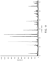
- Figure 11 is an X-ray diffraction spectra of crystalline oxide material (ii).
- black pigment Black 1G (available from The Shepherd Color Company) was subjected to wet bead-milling.
- the wet milling mixture comprised 50 wt.% pigment, 48.5 wt.% Dowanol TM DPM and 1.5 wt.% BykJet-9151 dispersant.
- the pigment was bead milled until a D90 particle size of approximately 0.6 ⁇ m was achieved. Particle size of the pigment was determined using a laser diffraction method using a Malvern Mastersizer 2000.
- a solution of resin was prepared by heating a mixture comprising 20 wt.% Klucel E3042 (available from Ashland Industries) and 80 wt.% Dowanol DPM to 90 °C with agitation. Heating and agitation of the mixture was continued until a homogenous, clear and thick solution was obtained.
- Inks 1 and 2 a suspension of glass frit particles, a suspension of particles of crystalline oxide material (i) and a suspension of pigment particles (each suspended in their respective milling liquids) were combined and then mixed with the resin solution prepared as described above and with isopropyl-alcohol solvent and BykJet-9151 surfactant to form an ink. Mixing was carried out at 3000 rpm for 2 minutes using a hi-speed mixer. Prior to combination with the other components, the suspension of glass frit particles and the suspension of particles of crystalline oxide material (i) were combined in relative proportions of 83 wt.% glass frit suspension and 17 wt.% crystalline oxide suspension and milled using a planetary mill for 2 hours at 350 rpm.
- Ink 3 To prepare Ink 3, a suspension of glass frit particles (suspended in milling liquid), a suspension of particles of crystalline oxide material (ii) (suspension prepared as described above) and a suspension of pigment particles (suspended in milling liquid) were combined and then mixed with the resin solution prepared as described above and with isopropyl-alcohol solvent and BykJet-9151 surfactant to form an ink. Mixing was carried out at 3000 rpm for 2 minutes using a hi-speed mixer.
- the suspension of glass frit particles and the suspension of particles of crystalline oxide material (ii) were combined in relative proportions of 83 wt.% glass frit suspension and 17 wt.% crystalline oxide suspension and milled using a planetary mill for 2 hours at 350 rpm.
- compositions of Inks 1, 2 and 3 are set out in Table 2 below.
- Table 2 Ink 1 Ink 2 Ink 3 Glass Frit (a) (b) (a) Crystalline Oxide Material (i) (i) (ii) Component Wt. % Suspension comprising 50wt.% glass frit particles 49.2 wt.% Dowanol TM DPM and 0.8 wt.% BykJet-9151 57.35 57.35 57.35 Suspension comprising 50wt.% particles of crystalline oxide material and 50 wt.% Dowanol TM DPM 11.75 11.75 11.75 Suspension comprising 50wt.% pigment particles 48.5 wt.% Dowanol TM DPM and 1.5 wt.% BykJet-9151 13.2 13.2 13.2 Isopropyl-alcohol 14.4 14.4 14.4 BykJet-9151 dispersant 2.5 2.5 2.5 2.5 Resin solution comprising 20 wt % Klucel E3042 and 80
- Ink 4 is commercially available black obscuration ink, 1T3030-IR815A available from Johnson Matthey having a solids portion with a D90 particle size in the range 8 ⁇ m to 12 ⁇ m.
- Ink 5 was prepared by combining Ink 3 with ammonia solution in the relative proportions 96 wt.% Ink 3 and 4 wt.% ammonia solution.
- the ammonia solution comprised 25 wt.% ammonia and was purchased from an Hees B.V. ( cas: 1336-21-6 ).
- Glass articles A to D having enamels formed thereon were prepared according to the following procedure.
- Inks 1 and 2 were inkjet printed onto glass substrates using a Xaar's 1002 GS6 printhead, with a jetting frequency of 3 kHz, at 7 dpd (drops per dot) and 360 x 360 dpi (drops per inch) and a drop volume of 6 picolitres.
- the applied ink coatings were then dried at 120 °C for approximately 10 minutes. The thickness of each applied coating after drying is shown in Table 3.
- Glass article E having an enamel formed thereon was prepared according to the following procedure. Ink 3 was applied to a glass substrate via roller coating using Elcometer 3520 Baker Film Applicator. Ink 3 was coated on the substrate at wet layer thickness of 30 ⁇ m. The applied ink coating was then dried at 120 °C for approximately 10 minutes. The thickness of the applied coating after drying is shown in Table 3.
- Ink 4 was used to prepare glass articles F and G.
- the commercially available ink was screen printed onto glass substrates using a 90T mesh screen and a squeegee.
- the applied ink coatings were then dried at 120 °C for approximately 10 minutes.
- the thickness of the applied coatings after drying are shown in Table 3.
- Glass article H having an enamel formed thereon was prepared according to the following procedure. Ink 5 was applied to a glass substrate via screen printing using 77T mesh screen and a squeegee. The applied ink coating was then dried at 120 °C for approximately 10 minutes. The thickness of the applied coating after drying is shown in Table 3. Table 3 Glass Article A B C D E F G H Ink 1 1 2 2 3 4 4 5 Dried layer thickness ( ⁇ m) 78 8 60 15 15 30 15 7
- Each of coated glass articles A to H were heated to elevated temperature sufficient to soften the glass and to fire the printed coating and were simultaneously subjected to a press-bending process by the application of a shaped die at an applied force of 9.5 N.
- the conditions of heating and press-bending are set out in Table 4 below.
- the die employed for press bending was covered with a metal cloth.
- Enamelled glass articles A' to H' correspond to enamelled glass articles A to H and were prepared in exactly the same manner except that the coated glass articles were fired without being simultaneously subjected to press-bending.
- the degree of sticking which occurred during press-bending was assessed by visually checking enamelled glass articles A to H for the presence of mesh marks in the enamel left by the metal cloth cover of the press bending die, and by measuring surface roughness of each enamel.
- Surface roughness is measured by carrying out a surface contour scan on a 1cm section of the enamelled glass article using a NanoFocus ⁇ scan optical profilometer (available from NanoFocus AG).
- the average surface roughness (Ra) is the mean of peak heights and depths across the surface contour scan.
- the optical density of the enamel formed on each of glass articles A, B, E F and G was measured using a Tobias TQ densitometer (available from Tobias Associates, Inc). It was not possible to measure the optical density of the enamels formed on glass articles C and D due to the severe sticking which had occurred during press bending.
- Table 6 The measured optical densities and the thickness of the enamels after firing are shown in Table 6 below.
- Table 6 A B E F G Optical Density 4 - 4.8 4 - 4.8 3.8 3 - 3.5 2 - 3 Enamel thickness ( ⁇ m) 40 7 8 18 12
Landscapes
- Chemical & Material Sciences (AREA)
- Life Sciences & Earth Sciences (AREA)
- Engineering & Computer Science (AREA)
- Chemical Kinetics & Catalysis (AREA)
- General Chemical & Material Sciences (AREA)
- Geochemistry & Mineralogy (AREA)
- Materials Engineering (AREA)
- Organic Chemistry (AREA)
- Dispersion Chemistry (AREA)
- Composite Materials (AREA)
- Glass Compositions (AREA)
- Manufacturing Of Micro-Capsules (AREA)
Description
- The present invention relates in particular to a particle mixture suitable for applying an enamel to a substrate. The particle mixture may be employed in an ink suitable for use in a method of forming an enamel on a substrate.
- Enamels are widely used to decorate or produce coatings on glass and ceramic substrates, such as tableware, signage, tiles, architectural glass etc. Enamels are especially useful in forming coloured borders around glass sheets used for automotive windshields, side windows (sidelites) and rear windows (backlites). The coloured borders enhance appearance as well as preventing degradation of underlying adhesives by UV radiation. Moreover, the coloured borders may conceal buss bars and wiring connections of glass defrosting systems.
- Enamels typically comprise pigment and glass frit. In general, they are applied to a substrate (e.g. a windshield surface) as an ink, e.g. by screen printing. The ink may comprise particles of pigment and glass frit dispersed in a liquid dispersion medium. After application of a coating of ink to the substrate, the ink is typically dried and the applied coating undergoes firing, i.e. is subjected to heat treatment to cause the frit to melt and fuse to the substrate; thereby adhering an enamel to the substrate. During firing, the pigment itself typically does not melt, but is affixed to the substrate by or with the frit.
- Glass sheets for automotive use often undergo a pressure forming process to bend the glass into the desired final shape. Typically, such glass sheets are coated in the desired region with an ink via screen printing prior to being subjected to a pressure forming process at elevated temperatures. The elevated temperature employed during this process causes the coating to undergo firing whilst softening the glass sheet, which can then be formed into a desired final shape using a forming die or mould. However, a problem encountered during such pressure forming processes is that the enamel may adhere ("stick") to the die or mould employed.
- Pressure forming is also used, for example, in the production of glass bottles, architectural glass and appliance glass. In these examples, it may also be desirable to apply an enamel for decorative and/or functional reasons.
- Various approaches have been suggested to facilitate the pressure forming of glass with enamel compositions applied thereon in order to avoid the enamel adhering to the die or mould. One approach involves the use of crystallisable glass frits including precursors of a compound which can be crystallised upon firing, for example precursors of Zn2SiO4. Such crystallisable frits may be used in combination with a crystalline seed additive which promotes crystallisation of at least a portion of the precursors present in the frit during firing. Such a seed additive may, for example, comprise crystalline Zn2SiO4.
-
WO 2010/005629 A1 discloses lead free, cadmium free, bismuth free low melting high durability glass and enamel compositions. The compositions comprise silica, zinc, titanium, and boron oxide based glass frits. The resulting compositions can be used to decorate and protect automotive, beverage, architectural, pharmaceutical and other glass substrates. -
EP 2 817 268 B1 discloses lass and enamel compositions. The glass compositions include SiO2, Nb2O5, Na2O, B2O3, ZnO, Bi2O3, TiO2, MoOs, ZrO2, Y2O3, Al2O3, Li2O, and K2O. The glass compositions can be used to form an enamel on a substrate, for example, to decorate and/or protect the substrate. - Further, obscuration enamels for automotive use typically have a thickness in the
range 10 to 15 microns - this provides sufficient opacity to adequately block transmission of sunlight, such that degradation of underlying adhesives by exposure to UV radiation is prevented. It is known that the risk of glass weakening may increase proportionally to the thickness of an applied enamel. Thus, it would be desirable to provide an enamel of reduced thickness which still achieves the required opacity. - It has now been found that the use of a particle mixture comprising sulfur-containing zinc-silicate glass frit and a crystalline oxide material, wherein both the frit and the crystalline oxide material have a D90 particle size of less than 5 microns, may allow improved anti-stick performance and reduced enamel thickness to be achieved.
- According to the present invention, there is provided a particle mixture for forming an enamel in accordance with claim 1.
- According to a second aspect of the present invention, there is provided an ink for forming an enamel in accordance with claim 15.
- Also disclosed but not claimed herein is a method of preparing an ink comprising mixing:
- a) particles of glass frit, which glass frit comprises silicon oxide (SiO2), zinc oxide (ZnO) and sulfur (S);
- b) particles of a crystalline oxide material; and
- c) a liquid dispersion medium;
- Also disclosed but not claimed herein is a method of forming an enamel on a substrate, the method comprising applying a coating of an ink as described above onto the substrate and firing the applied coating.
- Also disclosed but not claimed herein is a substrate having an enamel formed thereon, wherein the enamel is obtained or obtainable by the method described above.
- According to yet another aspect, there is provided the use of a particle mixture as described above to form an enamel on a substrate. Also disclosed but not claimed herein is an ink as described above to form an enamel on a substrate.
- Also disclosed but not claimed herein is the use of a particle mixture or an ink as described above to form a coloured obscuration band around the periphery of a sheet of automotive glass, in particular a sheet of automotive glass which is subjected to a pressure-forming process.
- Also disclosed but not claimed herein is the use of a particle mixture or an ink as described above to form an enamel on appliance glass, for example, refrigerator glass, oven glass etc.
- Also disclosed but not claimed herein is a glass sheet having an enamel formed on at least a portion of a surface of the sheet, wherein the enamel has an optical density of at least 2.5 and a thickness of less than or equal to 12 microns.
- Also disclosed but not claimed herein is a glass sheet having a curved section and having an enamel formed on at least a portion of a surface of the curved section of the sheet, wherein the enamel has an optical density of at least 2.5 and a thickness of less than or equal to 12 microns.
- Also disclosed but not claimed herein is an automotive window pane comprising a glass sheet having a curved section and having an enamel formed on at least a portion of a surface of the curved section of the sheet, wherein the enamel has an optical density of at least 2.5 and a thickness of less than or equal to 12 microns.
- Also disclosed but not claimed herein is a kit comprising particles of glass frit and particles of a crystalline oxide material, wherein the glass frit comprises silicon oxide (SiO2), zinc oxide (ZnO) and sulfur (S) and wherein the D90 particle size of the glass frit is less than 5 microns and the D90 particle size of the crystalline oxide material is less than 5 microns.
-
-
Figure 1 shows a surface contour scan of an enamel formed on a glass article using a particle mixture according to the present invention. -
Figure 2 shows a surface contour scan of an enamel formed on a glass article using a comparative particle mixture. -
Figure 3 shows a surface contour scan of an enamel formed on a glass article using a particle mixture according to the present invention. -
Figure 4 shows a surface contour scan of an enamel formed on a glass article using a commercially available ink. -
Figure 5 shows a surface contour scan of an enamel formed on a glass article using a particle mixture according to the present invention. -
Figure 6 shows an optical microscope image of an enamel formed on a glass article using a particle mixture according to the present invention. -
Figure 7 shows an optical microscope image of an enamel formed on a glass article using a comparative particle mixture. -
Figure 8 shows an optical microscope image of an enamel formed on a glass article using a particle mixture according to the present invention. -
Figure 9 shows an optical microscope image of an enamel formed on a glass article using a commercially available ink. -
Figure 10 shows an optical microscope image of an enamel formed on a glass article using a particle mixture according to the present invention. -
Figure 11 is an x-ray diffraction spectra of a commercially available crystalline oxide material. - Preferred and/or optional features of the invention will now be set out. Any aspect of the invention may be combined with any other aspect of the invention unless the context demands otherwise. Any of the preferred and/or optional features of any aspect may be combined, either singly or in combination, with any aspect of the invention unless the context demands otherwise.
- The particle mixture of the present invention comprises particles of glass frit, which glass frit comprises silicon oxide (SiO2), zinc oxide (ZnO) and sulfur (S). The glass frit is preferably crystallisable, that is the glass frit includes precursors of a compound which can be crystallised upon firing. For example, the glass frit may include precursors from which Zn2SiO4 may be crystallised upon firing.
- The glass frit employed in the particle mixture of the present invention comprises at least 25 wt.%, and may comprise at least 28 wt.%, at least 30 wt.%, at least 33 wt.%, or at least 35 wt.% SiO2. The glass frit includes 65 wt.% or less, and may include 50 wt.% or less, 40 wt.% or less, or 37 wt.% or less of SiO2. The glass frit includes 25 to 65 wt.%, and may preferably include, 30 to 50 wt.% of SiO2.
- The glass frit includes at least 19 wt.%, and may include at least 20 wt.%, at least 22 wt.%, or at least 25 wt.% ZnO. The glass frit includes 59 wt.% or less, and may include 50 wt.% or less, 40 wt.% or less, 35 wt.% or less, or 30 wt.% or less of ZnO. The glass frit includes 19 to 59 wt.%, preferably 20 to 40 wt.% of ZnO.
- The glass frit includes greater than 0 wt.%, and may include at least 0.1 wt.%, at least 1 wt.%, at least 2 wt.%, at least 3 wt.% or at least 4 wt.% S. The glass frit includes 6 wt.% or less, and may include 5 wt.% or less, or 4 wt.% or less of S. For example, the glass frit may preferably include 0.1 to 5 wt.% of S.
- The glass frit compositions described herein are given as weight percentages. These weight percentages are with respect to the total weight of the glass frit composition. The weight percentages are the percentages of the components used as starting materials in preparation of the glass frit compositions, on an oxide or elemental basis. As the skilled person will understand, starting materials other than oxides or elemental forms of a specific element may be used in preparing the glass frits of the present invention. Where a non-oxide starting material is used to supply an oxide of a particular element to the glass frit composition, an appropriate amount of starting material is used to supply an equivalent molar quantity of the element had the oxide of that element been supplied at the recited wt.%. For components where weight percentage is quoted on an elemental basis and where a non-elemental starting material is used, an appropriate amount of starting material is used to supply a molar quantity of the element equivalent to that which would be supplied had an elemental form of the element been supplied at the recited wt.%. This approach to defining glass frit compositions is typical in the art. As the skilled person will readily understand, volatile species (such as oxygen) may be lost during the manufacturing process of the glass frit, and so the composition of the resulting glass frit may not correspond exactly to the weight percentages of starting materials, which are given herein on an oxide or elemental basis. Analysis of a fired glass frit by a process known to those skilled in the art, such as Inductively Coupled Plasma Emission Spectroscopy (ICP-ES), can be used to calculate the starting components of the glass frit composition in question.
- The glass frit employed in the particle mixture of the present invention may further comprise B2O3. For example, the glass frit may include at least 5 wt.%, at least 6 wt.%, or at least 7 wt.% of B2O3. The glass frit may include 14 wt.% or less, 12 wt.% or less, 10 wt.% or less, or 8 wt.% or less of B2O3. The glass frit may preferably include 7 to 14 wt.% of B2O3.
- The glass frit may further include alkali metal oxide, for example one or more selected from Li2O, Na2O, K2O, and Rb2O, preferably one or more selected from Li2O, Na2O and K2O. For example, the glass frit may include 2 wt.% or more, 4 wt.% or more, 6 wt.% or more, 6.5 wt.% or more, 7 wt.% or more, or 7.5 wt.% or more alkali metal oxide. The glass frit may include 18 wt.% or less, 15 wt.% or less, 14 wt.% or less, 12 wt.% or less, 10 wt.% or less, or 8 wt.% or less alkali metal oxide.
- The glass frit may include 0 wt.% or more, 0.1 wt.% or more, 0.5 wt.% or more, 1 wt.% or more, 2 wt.% or more, or 2.5 wt.% or more Li2O. The glass frit may include 4 wt.% or less, 3 wt.% or less, 2.5 wt.% or less, 2 wt.% or less Li2O. For example, the glass frit may include 1 to 3 wt.% of Li2O.
- The glass frit may include 0 wt.% or more, 0.1 wt.% or more, 0.5 wt.% or more, 1 wt.% or more, 2 wt.% or more, 3wt.% or more, 4 wt.% or more, or 5 wt.% or more Na2O. The glass frit may include 12 wt.% or less, 10 wt.% or less, 8 wt.% or less, 6 wt.% or less, or 5 wt.% or less Na2O. For example, the glass frit may include 2 to 6 wt.% of Na2O.
- The glass frit may include 0 wt.% or more, 0.1 wt.% or more, 0.5 wt.% or more, 1 wt.% or more, 1.5 wt.% or more, 2 wt.% or more K2O. The glass frit may include 3 wt.% or less 2.5 wt.% or less, 2 wt.% or less K2O. For example, the glass frit may include 1.5 to 3 wt.% of K2O.
- The glass frit may further comprise TiO2. The glass frit may include 0 wt.% or more, 1 wt.% or more, 2 wt.% or more, 2.75 wt.% or more, 3.5 wt.% or more, 4 wt.% or more, 5 wt.% or more, 5.5 wt.% or more, or 6 wt.% or more TiO2. The glass frit may include 10 wt.% or less, 8 wt.% or less, 6 wt.% or less TiO2. For example, the glass frit may include 0 to 10 wt.% of TiO2.
- The glass frit may further comprise F. The glass frit may include 0 wt.% or more, 0.1 wt.% or more, 0.2 wt.% or more, 0.3 wt.% or more, or 0.4 wt.% or more F. The glass frit may include 1 wt.%, 0.75 wt.% or less 0.6 wt.% or less, or 0.5 wt.% or less F. For example, the glass frit may include 0 to 1 wt.% of F.
- The glass frit may further comprise BaO. The glass frit may include 0 wt.% or more, 0.5 wt.% or more, 1 wt.% or more, BaO. The glass frit may include 2 wt.% or less, 1.8 wt.% or less, or 1.5 wt.% or less BaO. For example, the glass frit may include 0.1 to 2 wt.% of BaO.
- The glass frit may further comprise V2O5. The glass frit may include 0 wt.% or more, 0.1 wt.% or more, 0.5 wt.% or more, or 1 wt.% or more V2O5. The glass frit may include 2 wt.% or less, 1.5 wt.% or less, or 1 wt.% or less V2O5. For example, the glass frit may include 0.5 to 1.5 wt.% of V2O5.
- The glass frit may further comprise Ce2O3. The glass frit may include 0 wt.% or more, 0.1 wt.% or more, 0.2 wt.% or more, or 0.3 wt.% or more CeaOs. The glass frit may include 1 wt.% or less, 0.6 wt.% or less, or 0.5 wt.% or less Ce2O3. For example, the glass frit may include 0.1 to 0.5 wt.% of Ce2O3.
- The glass frit may further comprise NbaOs. The glass frit may include 0 wt.% or more, 0.1 wt.% or more, 0.2 wt.% or more, or 0.3 wt.% or more NbaOs. The glass frit may include 1 wt.% or less, 0.6 wt.% or less, or 0.5 wt.% or less Nb2O5. For example, the glass frit may include 0.1 to 0.5 wt.% of Nb2O5.
- In some embodiments, the glass frit is substantially lead-free. As used herein, the term "substantially lead-free" is intended to include glass frits which contain no intentionally added lead. For example, the glass frit may include less than 0.1 wt.% PbO, for example less than 0.05 wt.%, less than 0.01 wt.% or less than 0.005 wt.% PbO.
- The glass frit may further comprise Bi2O3. The glass frit may include 1 wt.% or more, 5 wt.% or more, 10 wt.% or more, or 25 wt.% or more BizOs. The glass frit may include 50 wt.% or less, 40 wt.% or less, or 35 wt.% or less Bi2O3. For example, the glass frit may include 0 to 25 wt.% of Bi2O3.
- In an alternative embodiment, the glass frit is substantially bismuth-free. As used herein, the term "substantially bismuth-free" is intended to include glass frits which contain no intentionally added bismuth. For example, the glass frit may include less than 0.1 wt.% Bi2O3, for example less than 0.05 wt.%, less than 0.01 wt.% or less than 0.005 wt.% Bi2O3.
- The glass frit may include further components, such as further oxide components. Typically, the glass frit will include 20 wt.% or less, 10 wt.% or less, 7 wt.% or less, 5 wt.% or less, 3 wt.% or less, 2 wt.% or less, or 1 wt.% or less in total of further components. The glass frit may include at least 0.1 wt.% of further components. The further components may be one or more selected from the group consisting of magnesium oxide (MgO), aluminium oxide (Al2O3), and/or zirconium oxide (ZrO2).
- In one embodiment of the present invention, the glass frit may comprise:
- a) 25 to 65 wt.% SiC2;*
- b) 19 to 50 wt.% ZnO;
- c) > 0 to 6 wt.% S;
- d) 0 to 40 wt.% Bi2O3;
- e) 7 to 14 wt.% B2O3;
- f) 0 to 3 wt.% Li2O;
- g) 0 to 7 wt.% TiO2;
- h) 4 to 12 wt.% Na2O;
- i) 0 to 3 wt.% K2O;
- j) 0 to 1 wt.% F;
- k) 0 to 2 wt.% BaO;
- l) 0 to 1 wt.% V2O5;
- m) 0 to 1 wt.% Ce2O3; and
- n) 0 to 1 wt.% Nb2O5.
- The glass frit may consist essentially of a composition as described herein, and incidental impurities. In that case, as the skilled person will readily understand that the total weight % of the recited constituents will be 100 wt.%, any balance being incidental impurities. Typically, any incidental impurity will be present at 0.1 wt.% or less, 0.05 wt.% or less, 0.01 wt.% or less, 0.05 wt.% or less, 0.001 wt.% or less, or 0.0001 wt.% or less.
- In one embodiment, the glass frit may consist essentially of:
- a) 25 to 65 wt.% SiO2;
- b) 19 to 50 wt.% ZnO;
- c) > 0 to 6 wt.% S;
- d) 0 to 40 wt.% Bi2O3;
- e) 7 to 14 wt.% B2O3;
- f) 0 to 3 wt.% Li2O;
- g) 0 to 7 wt.% TiO2;
- h) 4 to 12 wt.% Na2O;
- i) 0 to 3 wt.% K2O;
- j) 0 to 1 wt.% F;
- k) 0 to 2 wt.% BaO;
- l) 0 to 1 wt.% V2O5;
- m) 0 to 1 wt.% Ce2O3;
- n) 0 to 1 wt.% Nb2O5;
- o) 0 to 10 wt.% of further components, which may optionally be selected from the group consisting of MgO, Al2O3 and/or ZrO2; and
- p) incidental impurities.
- In the particle mixture of the present invention, the D90 particle size of the particles of glass frit is less than 5 microns. The D90 particle size of the particles of glass frit may be less than 4.8 microns, less than 4 microns, less than 3.5 microns, less than 3 microns, less than 2.5 microns, less than 2 microns, or less than 1.5 microns.
- The term "D90 particle size" herein refers to particle size distribution, and a value for D90 particle size corresponds to the particle size value below which 90%, by volume, of the total particles in a particular sample lie. The D90 particle size may be determined using a laser diffraction method (e.g. using a Malvern Mastersizer 2000).
- In the particle mixture of the present invention, the D50 particle size of the particles of glass frit may be less than 1 micron, less than 0.9 microns, or less than 0.75 microns.
- The term "D50 particle size" herein refers to particle size distribution, and a value for D50 particle size corresponds to the particle size value below which 50%, by volume, of the total particles in a particular sample lie. The D50 particle size may be determined using a laser diffraction method (e.g. using a Malvern Mastersizer 2000).
- Additionally, (with the caveat that the D90 particle size is always higher than the D50 particle size), the D90 particle size of the particles of glass frit may be at least 1 micron, at least 1.2 microns, or at least 1.4 microns.
- The particle mixture of the present invention may comprise a mixture of particles of two or more types of glass frit. However, it is preferred that the present invention employs a single frit system, i.e. the particle mixture of the present invention comprises particles of only one type of glass frit. In particular, where the present invention comprises a single frit system, it is preferred that the glass frit is substantially lead free, more preferably, the glass frit is substantially bismuth and lead free.
- The particles of glass frit may be prepared by mixing together the raw materials and melting them to form a molten glass mixture, then quenching to form a glass. The process may further comprise milling the resulting glass to provide glass frit particles of the desired particle size. For example, the glass may be milled using a bead-milling process, such as wet bead-milling in an alcohol-based or a water-based solvent. The skilled person is aware of alternative suitable methods for preparing glass frit. Suitable alternative methods include water quenching, sol-gel processes and spray pyrolysis.
- The particle mixture may comprise from 40 to 85 wt.% of glass frit, preferably 75-85 wt.% of glass frit, based on total weight of the particle mixture.
- The particle mixture of the present invention further comprises particles of a crystalline oxide material. As used herein, the term "crystalline oxide material" means an oxide material having a minimum degree of crystallinity of 30%, as determined using x-ray diffraction (XRD). For example, the crystalline oxide material may be an oxide compound having a crystallinity level in the
range 30 to 100%, as determined using XRD. The crystalline oxide material is typically a polycrystalline oxide material. - The crystalline oxide material may be selected from silicon oxides, zinc oxides, zinc borates, zinc silicates, silicon zirconates, aluminium silicates, calcium silicates and mixtures thereof. For example, the crystalline oxide material may be selected from SiO2, Zn2SiO4, ZnO.B2O3, 3ZnO.B2O3, 5ZnO.2B2O3, Al2SiO5 and mixtures thereof. Preferably, the crystalline oxide material comprises Zn2SiO4, for example, the crystalline oxide material may comprise manganese doped Zn2SiO4.
- In order to provide particles of the crystalline oxide material of the desired particle size, the crystalline oxide material may be subjected to milling. For example, the crystalline oxide material may be milled using a bead-milling process, such as wet or dry bead-milling. Wet bead-milling may be carried out using an alcohol based solvent, for example butyl diglycol.
- The particle mixture may comprise from 0.1 to 15 wt.% of crystalline oxide material, preferably 0.1 to 10 wt.%, more preferably 0.1-5 wt.% of crystalline oxide material, based on total weight of the particle mixture.
- In the particle mixture of the present invention, the D90 particle size of the particles of crystalline oxide material is less than 5 microns. The D90 particle size of the particles of crystalline oxide material may be less than 4.8 microns, less than 4 microns, less than 3.5 microns, less than 3 microns, less than 2.5 microns, less than 2 microns, or less than 1.5 microns.
- Preferably, the D90 particle size of the particles of crystalline oxide material is less than or equal to the D90 particle size of the particles of glass frit. More preferably, the D90 particle size of the particles of crystalline oxide material is less than the D90 particle size of the particles of glass frit.
- Preferably, in the particle mixture of the present invention, the D50 particle size of the particles of crystalline oxide material is less than 1 micron, preferably less than 0.9 microns, more preferably less than 0.75 microns.
- Additionally, (with the caveat that the D90 particle size is always higher than the D50 particle size), the D90 particle size of the particles of crystalline oxide material may be at least 1 micron, at least 1.2 microns, or at least 1.4 microns.
- The weight ratio of glass frit to crystalline oxide material in the particle mixture of the present invention may be in the range 90.00 : 10.00 to 99.90 : 0.10. Preferably, the weight ratio of glass frit to crystalline oxide material in the present invention is in the range 99.00 : 1.00 to 99.90 : 0.10, more preferably in the range 99.50 : 0.50 to 99.85 : 0.15.
- The particle mixture may further comprise particles of a pigment, such as a mixed metal oxide pigment or a carbon black pigment. When used, such pigments may constitute no greater than about 55 wt.%, preferably 10-25 wt.% of the particle mixture, depending upon the range of colour, gloss, and opacity desired in the enamel.
- Suitable pigments may comprise complex metal oxide pigments, such as corundum-hematite, olivine, priderite, pyrochlore, rutile, and spinel. Other categories such as baddeleyite, borate, garnet, periclase, phenacite, phosphate, sphene and zircon may be suitable in certain applications.
- Typical complex metal oxide pigments which may be used to produce black colours in the automotive industry include transition metal oxides having spinel-structure, such as spinel-structure oxides of copper, chromium, iron, cobalt, nickel, manganese, and the like. Although these black spinel pigments are preferred for use in the automotive industry, other metal oxide pigments to produce other various colours can be employed in the present invention. Examples of other end uses include architectural, appliance, and beverage industries.
- Examples of commercially available pigments suitable for use in the present invention include CuCr2O4, (Co,Fe)(Fe,Cr)2O4, (NiMnCrFe), and the like.
- Mixtures of two or more pigments may also be employed in the particle mixture of the present invention.
- Preferably, the D90 particle size of the particles of pigment is less than or equal to the D90 particle size of the particles of glass frit. More preferably, the D90 particle size of the particles of pigment is less than the D90 particle size of the particles of glass frit.
- The D90 particle size of the particles of pigment may be less than 5 microns, less than 4 microns or less than 2 microns. Preferably, the D90 particle size of the particles of pigment is less than 1.2 microns.
- The particle mixture of the present invention may be prepared by mixing particles of glass frit and particles of crystalline oxide material. Where pigment is employed, the particle mixture may be prepared by mixing particles of glass frit, particles of crystalline oxide material and particles of pigment.
- The particle mixture of the present invention may be combined with a liquid dispersion medium to form an ink according to the second aspect of the present invention. As used herein, the term "liquid dispersion medium" refers to a substance which is in the liquid phase at the conditions intended for application of the ink to a substrate (i.e. printing). Thus, at ambient conditions the liquid dispersion medium may be solid or a liquid too viscous for printing. As the skilled person will readily understand, combination of the particle mixture with a liquid dispersion medium may take place at elevated temperature if required.
- The liquid dispersion medium to be employed in the ink of the present invention may be selected on the basis of the application method to be employed (for example, screen printing, roller coating or inkjet printing) and the intended end use of the enamel. Typically, the liquid dispersion medium comprises an organic liquid.
- In one embodiment, the liquid dispersion medium adequately suspends the particle mixture at application conditions, and is removed completely during drying and/or firing or pre-firing of the applied coating. Factors influencing the choice of medium include solvent viscosity, evaporation rate, surface tension, odour and toxicity. Suitable mediums preferably exhibit non-Newtonian behavior at printing conditions. Suitable mediums are typically organic. Suitably, the medium comprises one or more of water, alcohols, glycol ethers, lactates, glycol ether acetates, aldehydes, ketones, aromatic hydrocarbons and oils. Mixtures of two or more solvents are also suitable.
- In an alternative embodiment, the liquid dispersion medium may be curable on exposure to thermal or actinic (e.g. UV) radiation. In this embodiment, the liquid dispersion medium adequately suspends the particle mixture at application conditions, and is then cured by exposing the applied coating to thermal or actinic radiation. The components of the cured liquid dispersion medium will subsequently be removed during firing or pre-firing of the applied coating. Suitable curable liquid dispersion media may include, for example, cross-linkable acrylates and/or methoacrylates.
- Preferred liquid dispersion mediums include diethylene glycol monobutyl ether, dipropylene glycol monomethyl ether, tripropylene glycol monomethyl ether, dibasic esters, and 1-methoxy 2-propanol. A particularly preferred medium comprises dipropylene glycol monomethyl ether.
- The ink may further comprise one or more additives. These may include dispersing agents, such as, but not limited to those from the BYKJET, disperBYK, Solsperse or Dispex ranges, in particular BYKJET 9151, and/or rheology modifiers.
- The ink of the present invention may comprise from about 40 to about 80 wt.% of the particle mixture described above and about 20 to about 60 wt.% of the liquid dispersion medium, based on total weight of the ink. The skilled person would be capable of selecting the appropriate amounts of particle mixture and liquid dispersion medium according to the desired method of applying the ink to a substrate. For example, where the ink is to be applied to a substrate via screen printing, the ink may comprise about 50 to about 80 wt.% of the particle mixture. Where the ink is to be applied to a substrate via roller coating or inkjet printing, the ink may comprise about 40 to about 60 wt.% of the particle mixture.
- In some embodiments, the ink is preferably substantially lead-free, that is, any lead-containing components are substantially absent from the ink. For example, the ink may comprise less than 0.1 wt.% lead.
- In some embodiments, the ink is preferably substantially bismuth-free, that is, any bismuth-containing components are substantially absent from the ink. For example, the ink may comprise less than 0.1 wt.% bismuth.
- The rheology of the ink can be adjusted depending on the technique to be used to apply the ink onto a substrate. The viscosity of the ink can be modified by the use of viscous resins such as vinyl resins, solvents, film formers such as cellulosic materials, and the like, or by the addition of small amounts of ammonia solution. In one embodiment, for example where the ink is to be applied to the substrate via roller coating or inkjet printing, the ink may have a viscosity of less than 50 mPa.s at a shear rate of 1000 s-1 and a temperature of 25 °C, preferably less than 20 mPa.s at a shear rate of 1000 s-1 and a temperature of 25 °C. In another embodiment, for example where the ink is to be applied to a substrate via screen printing, the ink may have a viscosity in the range 8 to 20 Pa.s at a shear rate of 10 s-1 and a temperature of 25 °C.
- The ink of the present invention may be prepared by mixing:
- a) particles of glass frit, which glass frit comprises silicon oxide (SiO2), zinc oxide (ZnO) and sulfur (S);
- b) particles of a crystalline oxide material; and
- c) a liquid dispersion medium;
- The components may be mixed, for example, using a propeller mixer, a high shear mixer, or a bead-mill. In some embodiments, the liquid dispersion medium and/or the combined components may be heated prior to and/or during mixing.
- The ink of the present invention may be employed in a method of forming an enamel on a substrate. Such a method may comprise applying a coating of an ink as described above onto the substrate and firing the applied coating.
- The coating of ink may be applied to a substrate via a suitable printing method. In one embodiment, the coating of ink may be applied to a substrate via screen printing, for example, using a suitable screen and a squeegee. In another embodiment, the coating of ink may be applied to a substrate via roller coating. In a further embodiment, the ink is applied to the substrate via inkjet printing, wherein ink droplets are discharged by a digitally controlled print head directly onto a substrate. For example, thermal drop-on-demand inkjet printing and piezoelectric drop-on-demand inkjet printing techniques may be suitable.
- After application of the ink coating to the substrate and prior to firing, the applied coating may undergo a drying step for removal or partial removal of solvents present in the liquid dispersion medium. Drying may be carried out at temperatures of up to 200°C. Drying may be carried out, for example, by air drying the applied coating at ambient temperature, by heating the ink-coated substrate in a suitable oven, or by exposing the ink-coated substrate to infrared radiation.
- Alternatively, where an appropriate liquid dispersion medium is employed, the applied coating may undergo a curing step, for example, by exposing the applied coating to radiation capable of initiating curing.
- The applied coating may be fired by heating the coated substrate to a temperature sufficiently high to cause the glass frit to melt and fuse to the substrate, and to burn off any remaining components deriving from the liquid dispersion medium. For example, the firing may be carried out by heating the coated substrate to a temperature in the
range 500 to 1000 °C, for example, 540 to 840 °C. Heating the coated substrate may be carried out using a suitable furnace, such as a continuous line furnace. - Subsequent to any drying or curing steps and prior to firing of the applied coating, the coating may undergo a pre-firing step. As used herein "pre-firing" refers to heating the coated substrate to a temperature in the range >200 °C to 600 °C, for removal of non-volatile components deriving from the liquid dispersion medium, for example, non-volatile organics. Pre-firing may be carried out using a suitable furnace, such as a continuous line furnace.
- In the method of forming an enamel of the present invention, the substrate to which the ink is applied may be a glass substrate, a ceramic substrate or a metal substrate. In a preferred embodiment the substrate is a glass substrate.
- The coating of ink applied to the substrate, prior to any drying, firing or pre-firing steps, may have a thickness (wet film thickness) in the
range 10 to 60 microns. Where the ink is applied to the substrate via roller coating or inkjet printing, the coating of ink preferably has a wet film thickness in therange 20 to 40 microns. Where the ink is applied to the substrate via screen printing, the coating of ink preferably has a wet film thickness in therange 10 to 25 microns. - The thickness of the resulting enamel (after firing) may be less than or equal to 12 microns, preferably less than or equal to 11 microns, more preferably less than or equal to 10 microns.
- A particular advantage of the present invention is that the use of reduced particle sizes allows for enhanced particle packing within the particle mixture, which thereby allows high optical densities to be achieved at reduced enamel thicknesses.
- Optical density is an indicator of the opacity of the enamel. The optical density of a substance is the logarithmic ratio of the intensity of transmitted light to the intensity of the incident light passing through the substance. Optical density (OD) is expressed as the negative logarithm of transmittance (T), i.e. OD = -log10T, where transmittance is the ratio of the intensity of light transmitted through a sample to the intensity of the incident light. For automotive obscuration enamels, a minimum optical density of from 2 to 4 is generally required. Optical density of an enamel may be measured using a suitable densitometer, for example a Tobias TQ Densitometer (available from Tobias Associates, Inc).
- In a preferred embodiment of the method of forming an enamel on a substrate, the substrate is a glass sheet and the firing of the applied coating takes place immediately prior to or during a pressure forming process for shaping the glass sheet. For example, a coating of ink may be applied to a sheet of glass in the desired region and the coated glass may then be subjected to elevated temperature in order to cause firing of the coating and to cause softening of the glass sheet. The softened glass sheet may then be subjected to pressure forming using a die or mould, to bend the glass into its final desired shape. In such a process, it has been found that the present invention provides improved anti-stick properties, i.e. that it is less likely that the enamel will stick to the mould or die employed in pressure forming.
- In a particularly preferred embodiment, such a method may be employed to manufacture an automotive window having a coloured (typically black) obscuration enamel situated at the periphery of the window. For example, the method may be employed to apply an obscuration enamel to the periphery of a sheet of glass for use as an automotive side or rear window. The sheet of glass may undergo a tempering or toughening process prior to or after application of the enamel and any pressure forming steps.
- Alternatively, the method may be employed to apply an obscuration enamel to an automotive front windshield. Automotive front windshields are typically laminated glass windows. Laminated glass windows may comprise an interlayer of flexible plastic material disposed between inner and outer layers of glass. The interlayer may comprise, for example, polyvinylbutyral ("PVB"), polyvinyl chloride ("PVC"), polyurethane ("PU") or an ethyl vinyl acetate ("EVA"). The use of such laminated glass may increase penetration resistance of the windshield and reduce the risk of laceration by fragments of glas s during an impact. Automotive windshields comprised of laminated glass, typically have a coloured (e.g. black) obscuration enamel disposed at the periphery of one face of one of the glass layers, preferably the inner face of the outer layer of glass. Alternatively, the obscuration enamel may be disposed at the periphery of one face of each of the glass layers, for example the inner face of each layer of glass. In the method of the present invention, the coating of ink may be applied to the periphery of a face of one or both of the glass layers and fired prior to the assembly of the glass layers with the interlayer.
- In addition to the automotive uses described herein, the particle mixture and/or the ink of the present invention may be employed in the formation of decorative and/or functional enamels on glass for other purposes, such as architectural glass, appliance glass, glass bottles etc.
- Also disclosed but not claimed herein is a substrate having an enamel formed thereon, wherein the enamel is obtained or obtainable by applying a coating of an ink as described above onto the substrate and firing the applied coating.
- Also disclosed but not claimed herein is a glass sheet having an enamel formed on at least a portion of a surface of the sheet, wherein the enamel has an optical density of at least 2.5 and a thickness of less than or equal to 12 microns.
- Also disclosed but not claimed herein is a glass sheet having a curved section and having an enamel formed on at least a portion of a surface of the curved section of the sheet, wherein the enamel has an optical density of at least 2.5 and a thickness of less than or equal to 12 microns.
- Also disclosed but not claimed herein is an automotive window pane comprising a glass sheet having a curved section and having an enamel formed on at least a portion of a surface of the curved section of the sheet, wherein the enamel has an optical density of at least 2.5 and a thickness of less than or equal to 12 microns.
- In these aspects, the enamel may have a thickness of less than or equal to 12 microns, less than or equal to 11 microns, or less than or equal to 10 microns.
- Further, in these aspects, the enamel may have an optical density of greater than or equal to 2.5, preferably greater than or equal to 3, more preferably greater than or equal to 3.5.
- The invention will now be further described with reference to the following examples, which are illustrative, but not limiting of the invention.
- Particles of glass frits (a) and (b), having the compositions shown in Table 1 below, were prepared as follows. Commercially available raw materials were mixed using a laboratory mixer. The mixture of raw materials was melted in an alumina crucible, in a gas furnace. Melting was carried out at 1350 °C for 55 minutes. The resulting molten glass was quenched in water to obtain the glass frit.
- The glass was then subjected to jet milling to provide coarse milled glass frit particles having a D90 particle size of approximately 6 µm. The coarse milled glass frit particles were then subjected to wet bead-milling. The wet milling mixture comprised 50 wt.% glass frit, 49.2 wt.% Dowanol™ DPM (available from Dow) and 0.8 wt.% BykJet-9151 dispersant (available from Byk). The mixture was bead milled until the glass frit particles had a D90 particle size of approximately 1.4 µm. Particle size of the glass frit was determined using a laser diffraction method using a
Malvern Mastersizer 2000.Table 1 Component Weight % Frit (a) Comparative Frit (b) SiO2 42.9 43.95 ZnO 29.15 29.75 B2O3 7.43 7.40 Li2O 2.77 2.86 TiO2 7.31 7.05 Na2O 4.05 3.42 S 0.81 - K2O 2.35 2.43 F 0.45 0.40 BaO 1.31 0.95 V2O5 1.15 1.44 Ce2O3 0.33 0.34 - Particles of crystalline oxide material (i) were prepared by synthesizing a suitable crystalline oxide material and then subjecting the synthesized material to wet bead-milling. The wet milling mixture comprised 50 wt.% of the crystalline oxide material and 50 wt.% Dowanol™ DPM. The mixture was bead milled until the crystalline oxide material had a D90 particle size of approximately 1.4 µm. Particle size of crystalline oxide material (i) was determined using a laser diffraction method using a
Malvern Mastersizer 2000. - Crystalline oxide material (ii) is a commercially available single-phase, crystalline manganese-doped Zn2SiO4 having a D50 particle size of 254 nm (purchased from Sigma-Aldrich (cas: 68611-47-2)). A suspension of particles of crystalline oxide material (ii) was prepared by mixing the particles with Dowanol™ DPM solvent. The suspension comprised 50 wt.% Mn-doped Zn2SiO4particles and 50 wt.% Dowanol™ DPM.
Figure 11 is an X-ray diffraction spectra of crystalline oxide material (ii). - Commercially available black pigment Black 1G (available from The Shepherd Color Company) was subjected to wet bead-milling. The wet milling mixture comprised 50 wt.% pigment, 48.5 wt.% Dowanol™ DPM and 1.5 wt.% BykJet-9151 dispersant. The pigment was bead milled until a D90 particle size of approximately 0.6 µm was achieved. Particle size of the pigment was determined using a laser diffraction method using a
Malvern Mastersizer 2000. - A solution of resin was prepared by heating a mixture comprising 20 wt.% Klucel E3042 (available from Ashland Industries) and 80 wt.% Dowanol DPM to 90 °C with agitation. Heating and agitation of the mixture was continued until a homogenous, clear and thick solution was obtained.
- To prepare
Inks 1 and 2, a suspension of glass frit particles, a suspension of particles of crystalline oxide material (i) and a suspension of pigment particles (each suspended in their respective milling liquids) were combined and then mixed with the resin solution prepared as described above and with isopropyl-alcohol solvent and BykJet-9151 surfactant to form an ink. Mixing was carried out at 3000 rpm for 2 minutes using a hi-speed mixer. Prior to combination with the other components, the suspension of glass frit particles and the suspension of particles of crystalline oxide material (i) were combined in relative proportions of 83 wt.% glass frit suspension and 17 wt.% crystalline oxide suspension and milled using a planetary mill for 2 hours at 350 rpm. - To prepare Ink 3, a suspension of glass frit particles (suspended in milling liquid), a suspension of particles of crystalline oxide material (ii) (suspension prepared as described above) and a suspension of pigment particles (suspended in milling liquid) were combined and then mixed with the resin solution prepared as described above and with isopropyl-alcohol solvent and BykJet-9151 surfactant to form an ink. Mixing was carried out at 3000 rpm for 2 minutes using a hi-speed mixer. Prior to combination with the other components, the suspension of glass frit particles and the suspension of particles of crystalline oxide material (ii) were combined in relative proportions of 83 wt.% glass frit suspension and 17 wt.% crystalline oxide suspension and milled using a planetary mill for 2 hours at 350 rpm.
- The compositions of
Inks 1, 2 and 3 are set out in Table 2 below.Table 2 Ink 1 Ink 2Ink 3 Glass Frit (a) (b) (a) Crystalline Oxide Material (i) (i) (ii) Component Wt. % Suspension comprising 50wt.% glass frit particles 49.2 wt.% Dowanol™ DPM and 0.8 wt.% BykJet-9151 57.35 57.35 57.35 Suspension comprising 50wt.% particles of crystalline oxide material and 50 wt.% Dowanol™ DPM 11.75 11.75 11.75 Suspension comprising 50wt.% pigment particles 48.5 wt.% Dowanol™ DPM and 1.5 wt.% BykJet-9151 13.2 13.2 13.2 Isopropyl-alcohol 14.4 14.4 14.4 BykJet-9151 dispersant 2.5 2.5 2.5 Resin solution comprising 20 wt % Klucel E3042 and 80wt.% Dowanol DPM 0.8 0.8 0.8 - Ink 4 is commercially available black obscuration ink, 1T3030-IR815A available from Johnson Matthey having a solids portion with a D90 particle size in the range 8 µm to 12 µm.
- Ink 5 was prepared by combining Ink 3 with ammonia solution in the relative proportions 96 wt.% Ink 3 and 4 wt.% ammonia solution. The ammonia solution comprised 25 wt.% ammonia and was purchased from an Hees B.V. (cas: 1336-21-6).
- Glass articles A to D having enamels formed thereon were prepared according to the following procedure.
Inks 1 and 2 were inkjet printed onto glass substrates using a Xaar's 1002 GS6 printhead, with a jetting frequency of 3 kHz, at 7 dpd (drops per dot) and 360 x 360 dpi (drops per inch) and a drop volume of 6 picolitres. The applied ink coatings were then dried at 120 °C for approximately 10 minutes. The thickness of each applied coating after drying is shown in Table 3. - Glass article E having an enamel formed thereon was prepared according to the following procedure. Ink 3 was applied to a glass substrate via roller coating using Elcometer 3520 Baker Film Applicator. Ink 3 was coated on the substrate at wet layer thickness of 30 µm. The applied ink coating was then dried at 120 °C for approximately 10 minutes. The thickness of the applied coating after drying is shown in Table 3.
- Ink 4 was used to prepare glass articles F and G. The commercially available ink was screen printed onto glass substrates using a 90T mesh screen and a squeegee. The applied ink coatings were then dried at 120 °C for approximately 10 minutes. The thickness of the applied coatings after drying are shown in Table 3.
- Glass article H having an enamel formed thereon was prepared according to the following procedure. Ink 5 was applied to a glass substrate via screen printing using 77T mesh screen and a squeegee. The applied ink coating was then dried at 120 °C for approximately 10 minutes. The thickness of the applied coating after drying is shown in Table 3.
Table 3 Glass Article A B C D E F G H Ink 1 1 2 2 3 4 4 5 Dried layer thickness (µm) 78 8 60 15 15 30 15 7 - Each of coated glass articles A to H were heated to elevated temperature sufficient to soften the glass and to fire the printed coating and were simultaneously subjected to a press-bending process by the application of a shaped die at an applied force of 9.5 N. The conditions of heating and press-bending are set out in Table 4 below. The die employed for press bending was covered with a metal cloth.
Table 4 Glass Article A B C D E F G H Ink used to prepare glass article 1 1 2 2 3 4 4 5 Kiln temperature (OC) 780 840 780 840 840 780 840 780 Maximum temperature at surface of enamel (°C) 695 710 695 710 710 695 710 695 Duration (s) 180 130 180 130 130 180 130 180 Force applied (N) 9.5 9.5 9.5 9.5 9.5 9.5 9.5 9.5 - Enamelled glass articles A' to H' correspond to enamelled glass articles A to H and were prepared in exactly the same manner except that the coated glass articles were fired without being simultaneously subjected to press-bending.
- The degree of sticking which occurred during press-bending was assessed by visually checking enamelled glass articles A to H for the presence of mesh marks in the enamel left by the metal cloth cover of the press bending die, and by measuring surface roughness of each enamel. Surface roughness is measured by carrying out a surface contour scan on a 1cm section of the enamelled glass article using a NanoFocus µscan optical profilometer (available from NanoFocus AG). The average surface roughness (Ra) is the mean of peak heights and depths across the surface contour scan.
- For comparison, surface roughness (Ra) of enamelled glass articles A' to Hi was measured in the same manner. For glass articles A to H, an increase in surface roughness compared with the corresponding non-bent enamelled glass article, and/or the presence of mesh marks indicates that sticking has taken place during the press bending process.
- The results of the anti-stick testing are shown in Table 5 below.
Table 5 Enamelled Glass Article Ai Bi Ci Di Ei Fi Gi Hi Average Surface Roughness, Ra (microns) < 0.5 < 0.5 < 0.5 < 0.5 < 0.5 0.9 - 1.1 0.9-1.1 ∼0.9 Enamelled Glass Article A B C D E F G H Average Surface Roughness, Ra (microns) < 0.5 < 0.5 > 1.3 > 1.3 <0.5 0.9 - 1.7 >1.3 ∼0.9 Visual inspection ∗ ∗ ∗∗∗ ∗∗∗ ∗ ∗∗ ∗∗ ∗ ∗ No significant mesh marks visible
∗∗ Mesh marks clearly visible
∗∗∗ Severe mesh marks visible - The surface contour scans of the enamels formed on glass articles B, D, E, F and H, after firing, are shown in
Figures 1 to 5 respectively. Optical microscope images (taken using a Nikon SMZ800 with a 10x magnification) of enamelled glass articles B, D, E, G and H are shown inFigures 6 to 10 respectively. - The results shown in Table 5 and
Figures 1 to 10 demonstrate that the particle mixture of the present invention allows good anti-stick properties to be achieved when employed in the formation of an enamel on a glass substrate which is to be subjected to a pressure forming process. - The optical density of the enamel formed on each of glass articles A, B, E F and G was measured using a Tobias TQ densitometer (available from Tobias Associates, Inc). It was not possible to measure the optical density of the enamels formed on glass articles C and D due to the severe sticking which had occurred during press bending.
- The measured optical densities and the thickness of the enamels after firing are shown in Table 6 below.
Table 6 A B E F G Optical Density 4 - 4.8 4 - 4.8 3.8 3 - 3.5 2 - 3 Enamel thickness (µm) 40 7 8 18 12 - The results shown in Table 6 demonstrate that the particle mixture of the present invention allows high optical density to be achieved at reduced enamel thicknesses.
Claims (15)
- A particle mixture comprising particles of glass frit and particles of a crystalline oxide material, wherein the glass frit comprises 25 to 65 wt.% silicon oxide (SiO2), 19 to 59 wt.% zinc oxide (ZnO) and >0 to 6 wt.% sulfur (S) and wherein the D90 particle size of the particle mixture is less than 5 microns.
- A particle mixture as claimed in claim 1 wherein the glass frit further comprises:0 to 40 wt% Bi2O3;7 to 14 wt% B2O3;0 to 3 wt% Li2O;0 to 7 wt% TiO2;4 to 12 wt% Na2O;0 to 3 wt% K2O;0 to 1 wt% F;0 to 2 wt% BaO;0 to 1 wt% V2O5;0 to 1 wt% Ce2O3; and0 to 1 wt% Nb2O5.
- A particle mixture as claimed in any preceding claim wherein the glass frit comprises less than 0.1 wt.% PbO, preferably less than 0.05 wt.%, more preferably less than 0.01 wt.%, most preferably less than 0.005 wt.% PbO.
- A particle mixture as claimed in any preceding claim wherein the glass frit comprises less than 0.1 wt.% Bi2O3, preferably less than 0.05 wt.%, more preferably less than 0.01 wt.%, most preferably less than 0.005 wt.% Bi2O3.
- A particle mixture as claimed in any preceding claim wherein the D90 particle size of the particles of glass frit is less than 4 microns, preferably less than 3 microns, more preferably less than 2 microns, most preferably less than 1.5 microns.
- A particle mixture as claimed in any preceding claim wherein the crystalline oxide material is selected from silicon oxides, zinc oxides, zinc borates, zinc silicates, silicon zirconates, aluminium silicates, calcium silicates and mixtures thereof, optionally wherein the crystalline oxide material is selected from SiO2, Zn2SiO4, ZnO.B2O3, 3ZnO.B2O3, 5ZnO.2B2O3, Al2SiO5 and mixtures thereof.
- A particle mixture as claimed in any preceding claim wherein the D90 particle size of the particles of crystalline oxide material is less than 4 microns, preferably less than 3 microns, more preferably less than 2 microns, most preferably less than 1.5 microns.
- A particle mixture as claimed in any preceding claim wherein the D90 particle size of the particles of crystalline oxide material is less than the D90 particle size of the particles of glass frit.
- A particle mixture as claimed in any preceding claim wherein the weight ratio of glass frit to crystalline oxide material is in the range 90.00 : 10.00 to 99.90 : 0.10, preferably in the range 99.00 : 1.00 to 99.90 : 0.10, more preferably in the range 99.50 : 0.50 to 99.85 : 0.15.
- A particle mixture as claimed in any preceding claim which further comprises particles of pigment.
- A particle mixture as claimed in any preceding claim which further comprises particles of pigment, wherein the pigmentis a black pigment;or a transition metal oxide having spinel-structure, such as spinel-structure oxides of copper, chromium, iron, cobalt, nickel, manganese, or mixtures thereof;or wherein the pigment is selected from CuCr2O4, (Co,Fe)(Fe,Cr)2O4, (NiMnCrFe), and mixtures thereof.
- A particle mixture as claimed in any preceding claim comprising:40 to 85 wt.%, preferably 75 to 85 wt.%, of glass frit;0.1 to 15 wt.%, preferably 0.1 to 5 wt.%, of crystalline oxide material; and0 to 55 wt.%, preferably 10 to 25 wt.%, of pigment.
- A particle mixture as claimed in any preceding claim comprising 10 to 55 wt.% of pigment.
- Use of a particle mixture as claimed in claims 1 to 13 to form an enamel on a substrate.
- An ink for forming an enamel comprising:• a particle mixture as claimed in any of the claims 1 to 13; and• a liquid dispersion medium.
Applications Claiming Priority (2)
| Application Number | Priority Date | Filing Date | Title |
|---|---|---|---|
| GBGB1712762.2A GB201712762D0 (en) | 2017-08-09 | 2017-08-09 | Particle mixture |
| PCT/GB2018/052011 WO2019030469A1 (en) | 2017-08-09 | 2018-07-16 | Particle mixture |
Publications (2)
| Publication Number | Publication Date |
|---|---|
| EP3665131A1 EP3665131A1 (en) | 2020-06-17 |
| EP3665131B1 true EP3665131B1 (en) | 2023-05-03 |
Family
ID=59894890
Family Applications (1)
| Application Number | Title | Priority Date | Filing Date |
|---|---|---|---|
| EP18745700.7A Active EP3665131B1 (en) | 2017-08-09 | 2018-07-16 | Particle mixture |
Country Status (9)
| Country | Link |
|---|---|
| US (1) | US11708297B2 (en) |
| EP (1) | EP3665131B1 (en) |
| JP (1) | JP2020529380A (en) |
| KR (1) | KR102643997B1 (en) |
| CN (1) | CN111108073A (en) |
| ES (1) | ES2946918T3 (en) |
| GB (1) | GB201712762D0 (en) |
| MX (1) | MX2020001200A (en) |
| WO (1) | WO2019030469A1 (en) |
Families Citing this family (2)
| Publication number | Priority date | Publication date | Assignee | Title |
|---|---|---|---|---|
| US20230070792A1 (en) * | 2019-12-20 | 2023-03-09 | Agc Glass Europe | Enameled glazing |
| FR3118026B1 (en) * | 2020-12-22 | 2023-08-18 | Saint Gobain | Motor vehicle roof glazing |
Citations (10)
| Publication number | Priority date | Publication date | Assignee | Title |
|---|---|---|---|---|
| EP0505892B1 (en) | 1991-03-25 | 1997-01-22 | Degussa Ag | Glass frits and their use in enamel barrier layers to stop silver migration |
| US5925160A (en) | 1997-01-16 | 1999-07-20 | Cerdec Corporation | Partially crystallizing lead-free enamel composition for automobile glass |
| WO2007024375A2 (en) | 2005-08-24 | 2007-03-01 | Ferro Corporation | Forehearth concentrate and method for opalization of glass |
| WO2007032977A1 (en) | 2005-09-14 | 2007-03-22 | Ferro Corporation | Extended firing range enamels to produce frost effects |
| WO2010005629A1 (en) | 2008-07-10 | 2010-01-14 | Ferro Corporation | Zinc containing glasses and enamels |
| US20120282407A1 (en) | 2011-05-04 | 2012-11-08 | Ferro Corporation | Glass Frit Compositions For Enamels |
| US20150015638A1 (en) | 2013-07-15 | 2015-01-15 | Dip-Tech Ltd. | Ceramic inkjet inks |
| WO2015071670A1 (en) | 2013-11-15 | 2015-05-21 | Johnson Matthey Public Limited Company | Glass composition |
| EP2817268B1 (en) | 2012-02-25 | 2016-12-21 | Ferro Corporation | Glass enamel for automotive applications |
| EP2953909B1 (en) | 2013-02-11 | 2018-07-04 | Eurokera S.N.C. | Glass-ceramic item and enamel suitable for coating same |
Family Cites Families (7)
| Publication number | Priority date | Publication date | Assignee | Title |
|---|---|---|---|---|
| US4822396A (en) * | 1987-11-13 | 1989-04-18 | Ciba-Geigy Corporation | Method of shaping a coated glass sheet on a shaping die |
| US5153150A (en) | 1990-09-07 | 1992-10-06 | Ferro Corporation | Partially crystallizing enamel containing Zn2 SiO4 to be used for automobile side and rear lights |
| ITMI910747A1 (en) | 1991-03-20 | 1992-09-21 | Bayer Italia Spa | BLACK GLASS PASTES FOR WINDOWS AND THEIR PRODUCTION |
| JPH0967139A (en) | 1995-08-28 | 1997-03-11 | Nippon Sheet Glass Co Ltd | Frit composition for glass coloring |
| DE19605617A1 (en) * | 1996-02-15 | 1997-08-21 | Cerdec Ag | Black glass frit, process for its preparation and its use |
| US6346493B1 (en) * | 1999-10-27 | 2002-02-12 | Ferro Corporation | Decorative glass enamels |
| WO2016122833A1 (en) | 2015-01-26 | 2016-08-04 | Ferro Corporation | Grain boundary healing glasses and their use in transparent enamels, transparent colored enamels and opaque enamels |
-
2017
- 2017-08-09 GB GBGB1712762.2A patent/GB201712762D0/en not_active Ceased
-
2018
- 2018-07-16 KR KR1020207004867A patent/KR102643997B1/en active IP Right Grant
- 2018-07-16 EP EP18745700.7A patent/EP3665131B1/en active Active
- 2018-07-16 MX MX2020001200A patent/MX2020001200A/en unknown
- 2018-07-16 CN CN201880050337.XA patent/CN111108073A/en active Pending
- 2018-07-16 WO PCT/GB2018/052011 patent/WO2019030469A1/en unknown
- 2018-07-16 ES ES18745700T patent/ES2946918T3/en active Active
- 2018-07-16 JP JP2020504700A patent/JP2020529380A/en active Pending
- 2018-07-16 US US16/635,040 patent/US11708297B2/en active Active
Patent Citations (10)
| Publication number | Priority date | Publication date | Assignee | Title |
|---|---|---|---|---|
| EP0505892B1 (en) | 1991-03-25 | 1997-01-22 | Degussa Ag | Glass frits and their use in enamel barrier layers to stop silver migration |
| US5925160A (en) | 1997-01-16 | 1999-07-20 | Cerdec Corporation | Partially crystallizing lead-free enamel composition for automobile glass |
| WO2007024375A2 (en) | 2005-08-24 | 2007-03-01 | Ferro Corporation | Forehearth concentrate and method for opalization of glass |
| WO2007032977A1 (en) | 2005-09-14 | 2007-03-22 | Ferro Corporation | Extended firing range enamels to produce frost effects |
| WO2010005629A1 (en) | 2008-07-10 | 2010-01-14 | Ferro Corporation | Zinc containing glasses and enamels |
| US20120282407A1 (en) | 2011-05-04 | 2012-11-08 | Ferro Corporation | Glass Frit Compositions For Enamels |
| EP2817268B1 (en) | 2012-02-25 | 2016-12-21 | Ferro Corporation | Glass enamel for automotive applications |
| EP2953909B1 (en) | 2013-02-11 | 2018-07-04 | Eurokera S.N.C. | Glass-ceramic item and enamel suitable for coating same |
| US20150015638A1 (en) | 2013-07-15 | 2015-01-15 | Dip-Tech Ltd. | Ceramic inkjet inks |
| WO2015071670A1 (en) | 2013-11-15 | 2015-05-21 | Johnson Matthey Public Limited Company | Glass composition |
Also Published As
| Publication number | Publication date |
|---|---|
| EP3665131A1 (en) | 2020-06-17 |
| JP2020529380A (en) | 2020-10-08 |
| CN111108073A (en) | 2020-05-05 |
| US11708297B2 (en) | 2023-07-25 |
| MX2020001200A (en) | 2020-09-25 |
| KR102643997B1 (en) | 2024-03-08 |
| KR20200040244A (en) | 2020-04-17 |
| GB201712762D0 (en) | 2017-09-20 |
| US20200247713A1 (en) | 2020-08-06 |
| ES2946918T3 (en) | 2023-07-27 |
| WO2019030469A1 (en) | 2019-02-14 |
Similar Documents
| Publication | Publication Date | Title |
|---|---|---|
| CN113548806B (en) | Method of manufacturing glazing, and glazing produced thereby | |
| JP5604428B2 (en) | Zinc-containing glass and enamel | |
| EP3169735B1 (en) | Ceramic ink jet printing ink for low-expansion glass and/or low-expansion glass-ceramic and use thereof | |
| CN112334423B (en) | Particulate mixture, kit, ink, method and article | |
| CN114040899B (en) | Enamel coating of coated glass substrates | |
| EP3665131B1 (en) | Particle mixture | |
| KR102058989B1 (en) | Temperable enamelled glass | |
| CN114981225A (en) | Roof pane for a motor vehicle | |
| WO2009147676A1 (en) | Printing process on inner side of laminated glass and glass laminates formed thereby | |
| TW202336177A (en) | Inkjet printable inks for fabricating enamel coatings |
Legal Events
| Date | Code | Title | Description |
|---|---|---|---|
| STAA | Information on the status of an ep patent application or granted ep patent |
Free format text: STATUS: UNKNOWN |
|
| STAA | Information on the status of an ep patent application or granted ep patent |
Free format text: STATUS: THE INTERNATIONAL PUBLICATION HAS BEEN MADE |
|
| PUAI | Public reference made under article 153(3) epc to a published international application that has entered the european phase |
Free format text: ORIGINAL CODE: 0009012 |
|
| STAA | Information on the status of an ep patent application or granted ep patent |
Free format text: STATUS: REQUEST FOR EXAMINATION WAS MADE |
|
| 17P | Request for examination filed |
Effective date: 20200114 |
|
| AK | Designated contracting states |
Kind code of ref document: A1 Designated state(s): AL AT BE BG CH CY CZ DE DK EE ES FI FR GB GR HR HU IE IS IT LI LT LU LV MC MK MT NL NO PL PT RO RS SE SI SK SM TR |
|
| AX | Request for extension of the european patent |
Extension state: BA ME |
|
| DAV | Request for validation of the european patent (deleted) | ||
| DAX | Request for extension of the european patent (deleted) | ||
| RAP1 | Party data changed (applicant data changed or rights of an application transferred) |
Owner name: JOHNSON MATTHEY ADVANCED GLASS TECHNOLOGIES B.V. |
|
| RAP3 | Party data changed (applicant data changed or rights of an application transferred) |
Owner name: FENZI AGT NETHERLANDS B.V. |
|
| RAP3 | Party data changed (applicant data changed or rights of an application transferred) |
Owner name: FENZI AGT NETHERLANDS B.V. |
|
| STAA | Information on the status of an ep patent application or granted ep patent |
Free format text: STATUS: EXAMINATION IS IN PROGRESS |
|
| 17Q | First examination report despatched |
Effective date: 20220713 |
|
| GRAP | Despatch of communication of intention to grant a patent |
Free format text: ORIGINAL CODE: EPIDOSNIGR1 |
|
| STAA | Information on the status of an ep patent application or granted ep patent |
Free format text: STATUS: GRANT OF PATENT IS INTENDED |
|
| INTG | Intention to grant announced |
Effective date: 20221125 |
|
| GRAS | Grant fee paid |
Free format text: ORIGINAL CODE: EPIDOSNIGR3 |
|
| GRAA | (expected) grant |
Free format text: ORIGINAL CODE: 0009210 |
|
| STAA | Information on the status of an ep patent application or granted ep patent |
Free format text: STATUS: THE PATENT HAS BEEN GRANTED |
|
| AK | Designated contracting states |
Kind code of ref document: B1 Designated state(s): AL AT BE BG CH CY CZ DE DK EE ES FI FR GB GR HR HU IE IS IT LI LT LU LV MC MK MT NL NO PL PT RO RS SE SI SK SM TR |
|
| REG | Reference to a national code |
Ref country code: GB Ref legal event code: FG4D |
|
| REG | Reference to a national code |
Ref country code: AT Ref legal event code: REF Ref document number: 1564489 Country of ref document: AT Kind code of ref document: T Effective date: 20230515 Ref country code: CH Ref legal event code: EP |
|
| REG | Reference to a national code |
Ref country code: DE Ref legal event code: R096 Ref document number: 602018049225 Country of ref document: DE |
|
| REG | Reference to a national code |
Ref country code: IE Ref legal event code: FG4D |
|
| P01 | Opt-out of the competence of the unified patent court (upc) registered |
Effective date: 20230501 |
|
| REG | Reference to a national code |
Ref country code: ES Ref legal event code: FG2A Ref document number: 2946918 Country of ref document: ES Kind code of ref document: T3 Effective date: 20230727 |
|
| REG | Reference to a national code |
Ref country code: NL Ref legal event code: FP |
|
| REG | Reference to a national code |
Ref country code: LT Ref legal event code: MG9D |
|
| REG | Reference to a national code |
Ref country code: AT Ref legal event code: MK05 Ref document number: 1564489 Country of ref document: AT Kind code of ref document: T Effective date: 20230503 |
|
| PG25 | Lapsed in a contracting state [announced via postgrant information from national office to epo] |
Ref country code: SE Free format text: LAPSE BECAUSE OF FAILURE TO SUBMIT A TRANSLATION OF THE DESCRIPTION OR TO PAY THE FEE WITHIN THE PRESCRIBED TIME-LIMIT Effective date: 20230503 Ref country code: PT Free format text: LAPSE BECAUSE OF FAILURE TO SUBMIT A TRANSLATION OF THE DESCRIPTION OR TO PAY THE FEE WITHIN THE PRESCRIBED TIME-LIMIT Effective date: 20230904 Ref country code: NO Free format text: LAPSE BECAUSE OF FAILURE TO SUBMIT A TRANSLATION OF THE DESCRIPTION OR TO PAY THE FEE WITHIN THE PRESCRIBED TIME-LIMIT Effective date: 20230803 Ref country code: AT Free format text: LAPSE BECAUSE OF FAILURE TO SUBMIT A TRANSLATION OF THE DESCRIPTION OR TO PAY THE FEE WITHIN THE PRESCRIBED TIME-LIMIT Effective date: 20230503 |
|
| PGFP | Annual fee paid to national office [announced via postgrant information from national office to epo] |
Ref country code: ES Payment date: 20230801 Year of fee payment: 6 |
|
| PG25 | Lapsed in a contracting state [announced via postgrant information from national office to epo] |
Ref country code: RS Free format text: LAPSE BECAUSE OF FAILURE TO SUBMIT A TRANSLATION OF THE DESCRIPTION OR TO PAY THE FEE WITHIN THE PRESCRIBED TIME-LIMIT Effective date: 20230503 Ref country code: PL Free format text: LAPSE BECAUSE OF FAILURE TO SUBMIT A TRANSLATION OF THE DESCRIPTION OR TO PAY THE FEE WITHIN THE PRESCRIBED TIME-LIMIT Effective date: 20230503 Ref country code: LV Free format text: LAPSE BECAUSE OF FAILURE TO SUBMIT A TRANSLATION OF THE DESCRIPTION OR TO PAY THE FEE WITHIN THE PRESCRIBED TIME-LIMIT Effective date: 20230503 Ref country code: LT Free format text: LAPSE BECAUSE OF FAILURE TO SUBMIT A TRANSLATION OF THE DESCRIPTION OR TO PAY THE FEE WITHIN THE PRESCRIBED TIME-LIMIT Effective date: 20230503 Ref country code: IS Free format text: LAPSE BECAUSE OF FAILURE TO SUBMIT A TRANSLATION OF THE DESCRIPTION OR TO PAY THE FEE WITHIN THE PRESCRIBED TIME-LIMIT Effective date: 20230903 Ref country code: HR Free format text: LAPSE BECAUSE OF FAILURE TO SUBMIT A TRANSLATION OF THE DESCRIPTION OR TO PAY THE FEE WITHIN THE PRESCRIBED TIME-LIMIT Effective date: 20230503 Ref country code: GR Free format text: LAPSE BECAUSE OF FAILURE TO SUBMIT A TRANSLATION OF THE DESCRIPTION OR TO PAY THE FEE WITHIN THE PRESCRIBED TIME-LIMIT Effective date: 20230804 |
|
| PGFP | Annual fee paid to national office [announced via postgrant information from national office to epo] |
Ref country code: DE Payment date: 20230704 Year of fee payment: 6 |
|
| PG25 | Lapsed in a contracting state [announced via postgrant information from national office to epo] |
Ref country code: FI Free format text: LAPSE BECAUSE OF FAILURE TO SUBMIT A TRANSLATION OF THE DESCRIPTION OR TO PAY THE FEE WITHIN THE PRESCRIBED TIME-LIMIT Effective date: 20230503 |
|
| PG25 | Lapsed in a contracting state [announced via postgrant information from national office to epo] |
Ref country code: SK Free format text: LAPSE BECAUSE OF FAILURE TO SUBMIT A TRANSLATION OF THE DESCRIPTION OR TO PAY THE FEE WITHIN THE PRESCRIBED TIME-LIMIT Effective date: 20230503 |
|
| PG25 | Lapsed in a contracting state [announced via postgrant information from national office to epo] |
Ref country code: SM Free format text: LAPSE BECAUSE OF FAILURE TO SUBMIT A TRANSLATION OF THE DESCRIPTION OR TO PAY THE FEE WITHIN THE PRESCRIBED TIME-LIMIT Effective date: 20230503 Ref country code: SK Free format text: LAPSE BECAUSE OF FAILURE TO SUBMIT A TRANSLATION OF THE DESCRIPTION OR TO PAY THE FEE WITHIN THE PRESCRIBED TIME-LIMIT Effective date: 20230503 Ref country code: RO Free format text: LAPSE BECAUSE OF FAILURE TO SUBMIT A TRANSLATION OF THE DESCRIPTION OR TO PAY THE FEE WITHIN THE PRESCRIBED TIME-LIMIT Effective date: 20230503 Ref country code: EE Free format text: LAPSE BECAUSE OF FAILURE TO SUBMIT A TRANSLATION OF THE DESCRIPTION OR TO PAY THE FEE WITHIN THE PRESCRIBED TIME-LIMIT Effective date: 20230503 Ref country code: DK Free format text: LAPSE BECAUSE OF FAILURE TO SUBMIT A TRANSLATION OF THE DESCRIPTION OR TO PAY THE FEE WITHIN THE PRESCRIBED TIME-LIMIT Effective date: 20230503 Ref country code: CZ Free format text: LAPSE BECAUSE OF FAILURE TO SUBMIT A TRANSLATION OF THE DESCRIPTION OR TO PAY THE FEE WITHIN THE PRESCRIBED TIME-LIMIT Effective date: 20230503 |
|
| REG | Reference to a national code |
Ref country code: DE Ref legal event code: R026 Ref document number: 602018049225 Country of ref document: DE |
|
| PLBI | Opposition filed |
Free format text: ORIGINAL CODE: 0009260 |
|
| PLAX | Notice of opposition and request to file observation + time limit sent |
Free format text: ORIGINAL CODE: EPIDOSNOBS2 |
|
| PG25 | Lapsed in a contracting state [announced via postgrant information from national office to epo] |
Ref country code: MC Free format text: LAPSE BECAUSE OF FAILURE TO SUBMIT A TRANSLATION OF THE DESCRIPTION OR TO PAY THE FEE WITHIN THE PRESCRIBED TIME-LIMIT Effective date: 20230503 |
|
| PG25 | Lapsed in a contracting state [announced via postgrant information from national office to epo] |
Ref country code: MC Free format text: LAPSE BECAUSE OF FAILURE TO SUBMIT A TRANSLATION OF THE DESCRIPTION OR TO PAY THE FEE WITHIN THE PRESCRIBED TIME-LIMIT Effective date: 20230503 |
|
| REG | Reference to a national code |
Ref country code: CH Ref legal event code: PL |
|
| 26 | Opposition filed |
Opponent name: VIBRANTZ GMBH Effective date: 20240131 |
|
| REG | Reference to a national code |
Ref country code: BE Ref legal event code: MM Effective date: 20230731 |
|
| PG25 | Lapsed in a contracting state [announced via postgrant information from national office to epo] |
Ref country code: LU Free format text: LAPSE BECAUSE OF NON-PAYMENT OF DUE FEES Effective date: 20230716 |
|
| PG25 | Lapsed in a contracting state [announced via postgrant information from national office to epo] |
Ref country code: LU Free format text: LAPSE BECAUSE OF NON-PAYMENT OF DUE FEES Effective date: 20230716 |
|
| GBPC | Gb: european patent ceased through non-payment of renewal fee |
Effective date: 20230803 |
|
| REG | Reference to a national code |
Ref country code: IE Ref legal event code: MM4A |
|
| PG25 | Lapsed in a contracting state [announced via postgrant information from national office to epo] |
Ref country code: CH Free format text: LAPSE BECAUSE OF NON-PAYMENT OF DUE FEES Effective date: 20230731 |
|
| PG25 | Lapsed in a contracting state [announced via postgrant information from national office to epo] |
Ref country code: SI Free format text: LAPSE BECAUSE OF FAILURE TO SUBMIT A TRANSLATION OF THE DESCRIPTION OR TO PAY THE FEE WITHIN THE PRESCRIBED TIME-LIMIT Effective date: 20230503 |
|
| PG25 | Lapsed in a contracting state [announced via postgrant information from national office to epo] |
Ref country code: SI Free format text: LAPSE BECAUSE OF FAILURE TO SUBMIT A TRANSLATION OF THE DESCRIPTION OR TO PAY THE FEE WITHIN THE PRESCRIBED TIME-LIMIT Effective date: 20230503 Ref country code: IT Free format text: LAPSE BECAUSE OF FAILURE TO SUBMIT A TRANSLATION OF THE DESCRIPTION OR TO PAY THE FEE WITHIN THE PRESCRIBED TIME-LIMIT Effective date: 20230503 Ref country code: BE Free format text: LAPSE BECAUSE OF NON-PAYMENT OF DUE FEES Effective date: 20230731 |
|
| PLAF | Information modified related to communication of a notice of opposition and request to file observations + time limit |
Free format text: ORIGINAL CODE: EPIDOSCOBS2 |
|
| PG25 | Lapsed in a contracting state [announced via postgrant information from national office to epo] |
Ref country code: IE Free format text: LAPSE BECAUSE OF NON-PAYMENT OF DUE FEES Effective date: 20230716 |
|
| PG25 | Lapsed in a contracting state [announced via postgrant information from national office to epo] |
Ref country code: GB Free format text: LAPSE BECAUSE OF NON-PAYMENT OF DUE FEES Effective date: 20230803 |
|
| PG25 | Lapsed in a contracting state [announced via postgrant information from national office to epo] |
Ref country code: IE Free format text: LAPSE BECAUSE OF NON-PAYMENT OF DUE FEES Effective date: 20230716 Ref country code: GB Free format text: LAPSE BECAUSE OF NON-PAYMENT OF DUE FEES Effective date: 20230803 |
|
| PGFP | Annual fee paid to national office [announced via postgrant information from national office to epo] |
Ref country code: FR Payment date: 20240604 Year of fee payment: 7 |
|
| PLBB | Reply of patent proprietor to notice(s) of opposition received |
Free format text: ORIGINAL CODE: EPIDOSNOBS3 |
|
| PGFP | Annual fee paid to national office [announced via postgrant information from national office to epo] |
Ref country code: NL Payment date: 20240708 Year of fee payment: 7 |