EP3665032B1 - Vorrichtung zur steuerung einer anpresskraft eines stromabnehmers mit einem relaisventil - Google Patents
Vorrichtung zur steuerung einer anpresskraft eines stromabnehmers mit einem relaisventil Download PDFInfo
- Publication number
- EP3665032B1 EP3665032B1 EP18737207.3A EP18737207A EP3665032B1 EP 3665032 B1 EP3665032 B1 EP 3665032B1 EP 18737207 A EP18737207 A EP 18737207A EP 3665032 B1 EP3665032 B1 EP 3665032B1
- Authority
- EP
- European Patent Office
- Prior art keywords
- pressure
- pilot control
- control circuit
- pilot
- pressures
- Prior art date
- Legal status (The legal status is an assumption and is not a legal conclusion. Google has not performed a legal analysis and makes no representation as to the accuracy of the status listed.)
- Active
Links
Images
Classifications
-
- B—PERFORMING OPERATIONS; TRANSPORTING
- B60—VEHICLES IN GENERAL
- B60L—PROPULSION OF ELECTRICALLY-PROPELLED VEHICLES; SUPPLYING ELECTRIC POWER FOR AUXILIARY EQUIPMENT OF ELECTRICALLY-PROPELLED VEHICLES; ELECTRODYNAMIC BRAKE SYSTEMS FOR VEHICLES IN GENERAL; MAGNETIC SUSPENSION OR LEVITATION FOR VEHICLES; MONITORING OPERATING VARIABLES OF ELECTRICALLY-PROPELLED VEHICLES; ELECTRIC SAFETY DEVICES FOR ELECTRICALLY-PROPELLED VEHICLES
- B60L5/00—Current collectors for power supply lines of electrically-propelled vehicles
-
- F—MECHANICAL ENGINEERING; LIGHTING; HEATING; WEAPONS; BLASTING
- F15—FLUID-PRESSURE ACTUATORS; HYDRAULICS OR PNEUMATICS IN GENERAL
- F15B—SYSTEMS ACTING BY MEANS OF FLUIDS IN GENERAL; FLUID-PRESSURE ACTUATORS, e.g. SERVOMOTORS; DETAILS OF FLUID-PRESSURE SYSTEMS, NOT OTHERWISE PROVIDED FOR
- F15B11/00—Servomotor systems without provision for follow-up action; Circuits therefor
- F15B11/02—Systems essentially incorporating special features for controlling the speed or actuating force of an output member
- F15B11/028—Systems essentially incorporating special features for controlling the speed or actuating force of an output member for controlling the actuating force
-
- B—PERFORMING OPERATIONS; TRANSPORTING
- B60—VEHICLES IN GENERAL
- B60L—PROPULSION OF ELECTRICALLY-PROPELLED VEHICLES; SUPPLYING ELECTRIC POWER FOR AUXILIARY EQUIPMENT OF ELECTRICALLY-PROPELLED VEHICLES; ELECTRODYNAMIC BRAKE SYSTEMS FOR VEHICLES IN GENERAL; MAGNETIC SUSPENSION OR LEVITATION FOR VEHICLES; MONITORING OPERATING VARIABLES OF ELECTRICALLY-PROPELLED VEHICLES; ELECTRIC SAFETY DEVICES FOR ELECTRICALLY-PROPELLED VEHICLES
- B60L5/00—Current collectors for power supply lines of electrically-propelled vehicles
- B60L5/18—Current collectors for power supply lines of electrically-propelled vehicles using bow-type collectors in contact with trolley wire
- B60L5/22—Supporting means for the contact bow
- B60L5/28—Devices for lifting and resetting the collector
- B60L5/32—Devices for lifting and resetting the collector using fluid pressure
-
- G—PHYSICS
- G05—CONTROLLING; REGULATING
- G05D—SYSTEMS FOR CONTROLLING OR REGULATING NON-ELECTRIC VARIABLES
- G05D16/00—Control of fluid pressure
- G05D16/20—Control of fluid pressure characterised by the use of electric means
- G05D16/2006—Control of fluid pressure characterised by the use of electric means with direct action of electric energy on controlling means
- G05D16/2013—Control of fluid pressure characterised by the use of electric means with direct action of electric energy on controlling means using throttling means as controlling means
- G05D16/2024—Control of fluid pressure characterised by the use of electric means with direct action of electric energy on controlling means using throttling means as controlling means the throttling means being a multiple-way valve
-
- H—ELECTRICITY
- H01—ELECTRIC ELEMENTS
- H01R—ELECTRICALLY-CONDUCTIVE CONNECTIONS; STRUCTURAL ASSOCIATIONS OF A PLURALITY OF MUTUALLY-INSULATED ELECTRICAL CONNECTING ELEMENTS; COUPLING DEVICES; CURRENT COLLECTORS
- H01R41/00—Non-rotary current collectors for maintaining contact between moving and stationary parts of an electric circuit
-
- B—PERFORMING OPERATIONS; TRANSPORTING
- B60—VEHICLES IN GENERAL
- B60L—PROPULSION OF ELECTRICALLY-PROPELLED VEHICLES; SUPPLYING ELECTRIC POWER FOR AUXILIARY EQUIPMENT OF ELECTRICALLY-PROPELLED VEHICLES; ELECTRODYNAMIC BRAKE SYSTEMS FOR VEHICLES IN GENERAL; MAGNETIC SUSPENSION OR LEVITATION FOR VEHICLES; MONITORING OPERATING VARIABLES OF ELECTRICALLY-PROPELLED VEHICLES; ELECTRIC SAFETY DEVICES FOR ELECTRICALLY-PROPELLED VEHICLES
- B60L2200/00—Type of vehicles
- B60L2200/26—Rail vehicles
-
- F—MECHANICAL ENGINEERING; LIGHTING; HEATING; WEAPONS; BLASTING
- F15—FLUID-PRESSURE ACTUATORS; HYDRAULICS OR PNEUMATICS IN GENERAL
- F15B—SYSTEMS ACTING BY MEANS OF FLUIDS IN GENERAL; FLUID-PRESSURE ACTUATORS, e.g. SERVOMOTORS; DETAILS OF FLUID-PRESSURE SYSTEMS, NOT OTHERWISE PROVIDED FOR
- F15B2211/00—Circuits for servomotor systems
- F15B2211/50—Pressure control
- F15B2211/52—Pressure control characterised by the type of actuation
- F15B2211/528—Pressure control characterised by the type of actuation actuated by fluid pressure
-
- F—MECHANICAL ENGINEERING; LIGHTING; HEATING; WEAPONS; BLASTING
- F15—FLUID-PRESSURE ACTUATORS; HYDRAULICS OR PNEUMATICS IN GENERAL
- F15B—SYSTEMS ACTING BY MEANS OF FLUIDS IN GENERAL; FLUID-PRESSURE ACTUATORS, e.g. SERVOMOTORS; DETAILS OF FLUID-PRESSURE SYSTEMS, NOT OTHERWISE PROVIDED FOR
- F15B2211/00—Circuits for servomotor systems
- F15B2211/60—Circuit components or control therefor
- F15B2211/63—Electronic controllers
- F15B2211/6303—Electronic controllers using input signals
- F15B2211/6306—Electronic controllers using input signals representing a pressure
- F15B2211/6313—Electronic controllers using input signals representing a pressure the pressure being a load pressure
-
- F—MECHANICAL ENGINEERING; LIGHTING; HEATING; WEAPONS; BLASTING
- F15—FLUID-PRESSURE ACTUATORS; HYDRAULICS OR PNEUMATICS IN GENERAL
- F15B—SYSTEMS ACTING BY MEANS OF FLUIDS IN GENERAL; FLUID-PRESSURE ACTUATORS, e.g. SERVOMOTORS; DETAILS OF FLUID-PRESSURE SYSTEMS, NOT OTHERWISE PROVIDED FOR
- F15B2211/00—Circuits for servomotor systems
- F15B2211/60—Circuit components or control therefor
- F15B2211/67—Methods for controlling pilot pressure
-
- H—ELECTRICITY
- H01—ELECTRIC ELEMENTS
- H01R—ELECTRICALLY-CONDUCTIVE CONNECTIONS; STRUCTURAL ASSOCIATIONS OF A PLURALITY OF MUTUALLY-INSULATED ELECTRICAL CONNECTING ELEMENTS; COUPLING DEVICES; CURRENT COLLECTORS
- H01R2201/00—Connectors or connections adapted for particular applications
- H01R2201/26—Connectors or connections adapted for particular applications for vehicles
Definitions
- the invention relates to a device for controlling a contact force of a current collector of a vehicle (for example a traction vehicle) on a contact line with a relay valve, a method for implementing such a device and a vehicle with at least one such device.
- a vehicle for example a traction vehicle
- the overhead line is a conventional or innovative overhead line, such as overhead conductor rails.
- the necessary contact forces increase sharply, particularly at high speeds (>200 km/h), to about twice the standstill value.
- the current state of the art uses wind deflectors in the pantograph, which on the one hand provide an additional aerodynamic force and on the other hand compensate for dynamic lift forces.
- the disadvantage here is that the design and handling of these wind deflectors cannot be easily adapted to different operating situations.
- the additional aerodynamic force in high-speed tunnels is significantly higher than on open track.
- this additional force also depends on the vehicle shape, tunnel cross-section, blocking dimension (ratio of vehicle cross-section to tunnel cross-section), cross-section jumps and position of the pantograph in the train. This additional force also depends on the direction of travel. (for example, depending on the skewer or knee path of an asymmetrical single-arm pantograph).
- pantograph contact force when the train is stationary in order to avoid overheating and damage to the contact strip and overhead line wire at the contact point when there is high current flow from lighting, air conditioning and passenger information systems on vehicles provided.
- wind deflectors cannot provide additional force when the locomotive is stationary.
- the current state of the art includes single-stage and two-stage (fixed but adjustable) pressures that press the pantograph onto the overhead line using a volume-variable lifting bellows.
- electro-pneumatic (ep) controlled pressure controls are already used, as shown in 2.8.
- EP1 539 528 A1 are known. It shows how the fallback level required by railway operators is implemented via a switching valve in the event of a fault in the ep controller.
- an ep controller is switched to a fixed, adjustable pressure reducing valve.
- the ep controller controls the contact pressure in the normal operation of the traction vehicle.
- the disadvantage here is that the contact pressure cannot be controlled precisely enough via the controller and high air consumption is caused.
- a pneumatic control of a current collector with a pressure control means for regulating the contact pressure is known, whereby a pilot control signal is fed to the pressure control means as a setpoint signal and thus the contact pressure of the current collector on an electrical line can be adapted to the circumstances of the respective driving situation,
- the invention is therefore based on the object of creating a device which carries out a more precise control of the required contact forces between a pantograph and a contact line, which are better suited to different operating situations.
- the solution to the problem consists in a device for controlling a contact force between a contact line and a pantograph of a vehicle, which is operated pneumatically or hydraulically.
- Air or oil for example, can be used as pressure media.
- the media pressure is in equilibrium with the gravity (weight) of the pantograph.
- the required contact force is achieved by increasing the working pressure, which is made possible by controlling or regulating a power pressure using two pilot pressures from a pilot circuit. If the operating situation requires an additional contact force, the pilot pressure in the pilot circuit is adjusted to control the power pressure and increase the working pressure.
- the device has a relay valve, which has at least two inputs for the pilot pressures with a small cross section and one input for the power pressure and one output for the working pressure with large cross sections, so that a transmission ratio is provided. An addition of several pilot pressures takes place at the inputs of the relay valve in order to control a power pressure.
- the pilot control circuit has a basic control circuit including a basic control device (e.g. a pressure reducing valve) for setting a first pilot pressure (a basic pilot pressure), an additional control circuit including an additional control device (e.g. a regulator) for setting a second pilot pressure and an adjustment device including a relay valve for controlling the power pressure and for providing the working pressure.
- a basic control device e.g. a pressure reducing valve
- an additional control circuit e.g. a regulator
- an adjustment device including a relay valve for controlling the power pressure and for providing the working pressure.
- a working pressure control circuit is provided which determines whether the working pressure is quickly or slowly increased to the pantograph.
- the working pressure control circuit can be configured to limit the working pressure to a maximum value in order to avoid excessive pressure on the pantograph or the contact line in order to prevent damage.
- the relay valve is designed in such a way that two inputs are provided for two pilot pressures, each with a small cross-section, and one input for the power pressure and one output for the working pressure with large cross-sections are provided so that a highly dynamic pilot pressure control can usually be translated 1:1 to the high-volume working pressure.
- a transmission ratio other than 1:1 can be implemented in one design variant. For example, if the transmission ratio 1:5 is selected, 10 bar in the pilot circuit has an effect on an output pressure of 2 bar at the output of the relay valve. In this case, a deviation is also reduced proportionally.
- the deviation in the pilot circuit is ⁇ 0.1 bar
- the deviation in the output of the relay valve is only ⁇ 0.02 bar, which corresponds to an absolute reduction in the deviation, and thus enables an increase in control accuracy and a reduction in hysteresis.
- the pilot control circuit preferably has a pressure sensor and two control valves.
- the pressure sensor is provided to provide pressure signals to the controller of the pilot control circuit. Due to the small control volume of the pilot control circuit, the higher dynamics can contribute to achieving greater control accuracy.
- the high resolution of the pressure sensor enables a low control level (low pressures) of the controller of the additional control circuit, and this enables a smaller tolerance (higher control accuracy) to be achieved with a smaller hysteresis.
- a constant control volume is always available to the pilot circuit because the variable working volume is separated from the relay valve.
- the pilot circuit regulator can adjust the pressure more precisely than a direct variable volume working pressure regulator.
- a state machine is provided to monitor the controller, among other things, in order to monitor the working pressure to see whether it falls below a minimum pressure setting, exceeds a maximum pressure setting, or deviates from a range between the target and actual value. If one of these cases occurs, a quick shutdown takes place.
- the quick shutdown acts on the pilot control circuit.
- a certain quick shutdown working pressure can be set.
- the quick shutdown can also act on the power pressure and thus prevent the supply to the relay valve, whereby the working pressure is released in any case.
- a state machine for example, an electrical, electronic or microprocessor unit (if necessary with software classified according to a safety level) can be used to monitor the working pressure. Comparison signals for this monitoring device can be obtained from the pressure sensor of the additional control circuit and/or a pressure sensor provided for the working pressure.
- Another advantage of the invention is that the device is designed in such a way that no consumption of pressure media occurs when the contact pressure remains unchanged, thus avoiding constant media consumption, which causes a high number of compressor running cycles in the vehicle, which lead to significant energy waste, noise generation and wear on the compressor.
- the resulting energy efficiency ensures the energy supply to the vehicle, especially when significant amounts of energy are required for lighting and air conditioning via the power collector to the vehicle.
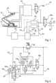
- Fig. 1 shows a part of a vehicle 10, a pantograph 12, a contact line 20 and a control device 22 of the pantograph 12.
- the pressure medium air flows in the inflow direction 90 from a pressure inlet 24 via an air filter 34 into the control device 22.
- control device 22 When the vehicle 10 is in operation or standby mode, the control device 22 is switched on via a switching valve 28a.
- a switching valve 28b and a device 30 represent monitoring devices.
- a certain contact pressure is required between the pantograph 12 and the overhead line 20 in order to ensure a safe transfer of energy from the overhead line 20 via the pantograph 12 to the vehicle 10.
- This working pressure is achieved by a pilot control circuit 32 with an adjustment device 50 and then controlled by a working pressure control circuit 60.
- the pilot control circuit 32 has a base control circuit 56, an additional control circuit 26 and an adjusting device 50.
- a power pressure is supplied to a first pressure medium line 52, the base control circuit 56 and the additional control circuit 26.
- the base control circuit 56 sets a first pilot pressure (base pilot pressure) and the additional control circuit 26 sets a second pilot pressure, wherein the first pilot pressure and the second pilot pressure are each fed via a second pressure medium line 54 to the adjusting device 50 in order to control the power pressure from the first pressure medium line 52 therein.
- Fig. 2 shows a pilot control circuit 32 of the control device 22 according to a first embodiment of the invention.
- the pilot control circuit 32 has a Pressure reducing valve 36, a changeover valve 280, an additional control circuit 26 including a regulator 38, a pressure sensor 72a, a first control valve 76 for pressure reduction, a second control valve 78 for pressure build-up, a relay valve 40 and a pressure sensor 72b.
- the pressure reducing valve 36 is designed to adjust the first pilot pressure (basic pilot pressure) and the regulator 38 is designed to adjust the second pilot pressure (additional pilot pressure), the basic pilot pressure and the additional pilot pressure being each led via the second pressure medium line 54 to inlets 46a and 46b of the relay valve 40.
- the relay valve 40 is designed such that an addition of the pilot pressures takes place after the inlets 46a and 46b in order to control the power pressure from the first pressure medium line 52 with the added pilot pressure and to discharge the working pressure from an outlet 42 of the relay valve 40.
- the changeover valve 28c is provided to switch off the additional control circuit in an emergency.
- the pressure sensors 723 and 72b are provided to measure the additional pilot pressure in the additional control circuit 26 and the working pressure at the outlet 42 of the relay valve.
Landscapes
- Engineering & Computer Science (AREA)
- Physics & Mathematics (AREA)
- Fluid Mechanics (AREA)
- Mechanical Engineering (AREA)
- Power Engineering (AREA)
- Transportation (AREA)
- General Physics & Mathematics (AREA)
- Automation & Control Theory (AREA)
- General Engineering & Computer Science (AREA)
- Current-Collector Devices For Electrically Propelled Vehicles (AREA)
- Fluid-Pressure Circuits (AREA)
- Electric Propulsion And Braking For Vehicles (AREA)
Description
- Die Erfindung betrifft eine Vorrichtung zur Steuerung einer Anpresskraft eines Stromabnehmers eines Fahrzeugs (beispielsweise eines Triebfahrzeugs) an eine Fahrleitung mit einem Relaisventil, ein Verfahren zum Ausführen einer derartigen Vorrichtung sowie einen Fahrzeug mit mindestens einer derartigen Vorrichtung.
- Stromabnehmer elektrischer Triebfahrzeuge benötigen eine definierte Anpresskraft an die Fahrleitung. Die Fahrleitung ist im gegenständlichen Fall eine Oberleitung konventioneller Ausführung oder innovativer Ausführung wie z.B. Deckenstromschienen.
- Ist diese Anpresskraft zu klein, fängt der Stromabnehmer zu springen an. Die daraus resultierenden Kontaktunterbrechungen und Lichtbögen beeinträchtigen die Lebensdauer von Stromabnehmer-Schleifleisten und Fahrleitungen. Ist diese Anpresskraft zu groß, wird die Fahrleitung übermäßig angehoben. Bei unzulässigen Krafteinleitungen in die Fahrleitung kann deren mechanische Positionierung nicht sichergestellt werden, ein "Einfädeln" des Stromabnehmers und Herunterreißen der Fahrleitung sind typische Konsequenzen.
- Die notwendigen Anpresskräfte sind insbesondere bei Hochgeschwindigkeitsbetrieb (>200km/h) stark ansteigend bis etwa zum Doppelten des Stillstandwertes. Um diesen Anstieg zu gewährleisten, werden nach Stand der Technik Windleitbleche im Stromabnehmer verwendet, die einerseits aerodynamisch eine Zusatzkraft aufbringen und andererseits dynamische Auftriebskräfte kompensieren. Nachteilig ist hierbei, dass die Auslegung und Handhabung dieser Windleitbleche nicht einfach an unterschiedliche Betriebssituationen anpassbar ist. Beispielsweise ist die aerodynamische Zusatzkraft in Hochgeschwindigkeitstunneln signifikant höher als auf freier Strecke. Diese Zusatzkraft ist jedoch auch von Fahrzeugform, Tunnelquerschnitt, Versperrungsmaß (Verhältnis Fahrzeugquerschnitt zu Tunnelquerschnitt), Querschnittssprüngen und Position des Stromabnehmers im Zugverband abhängig. Auch ist diese Zusatzkraft fahrtrichtungsabhängig (beispielweise je nach Spieß- oder Kniegang eines asymmetrischen Einholm-Stromabnehmers).
- Zusätzlich bestehen zunehmend Anforderungen, die Stromabnehmer-Anpresskraft im Stillstand anzuheben, um Überhitzung und Beschädigung von Schleifleiste und Fahrleitungsdraht im Kontaktpunkt bei hohem Stromfluss durch Beleuchtung, Klimaanlagen und Fahrgastinformationssysteme bei bereitgestellten Fahrzeugen zu vermeiden. Windleitbleche können jedoch keine Zusatzkraft aufbringen, wenn sich das Triebfahrzeug im Stillstand befindet.
- Aus dem Stand der Technik sind heute einstufige und zweistufige (festeingestellte, aber justierbare) Drücke bekannt, die den Stromabnehmer durch einen volumenvariablen Hebebalg an die Fahrleitung drücken. In einzelnen Fällen werden bereits elektronpneumatisch (ep) geregelte Druckansteuerungen verwendet, wie sie 2.8. aus
EP1 539 528 A1 bekannt sind. Darin wird gezeigt, wie die von Bahnbetreibern geforderte Rückfallebene bei Störung des ep-Reglers über ein Umschaltventil erfolgt. Ein ep-Regler wird im Störungsfall auf ein festeingestelltes justierbares Druckminderventil umgeschaltet. Der ep-Regler steuert die Anpresskraft im Regelbetrieb des Triebfahrzeuges. Nachteilig ist hierbei, dass die Anpresskraft über den Regler nicht genau genug angesteuert werden kann und hoher Luftverbrauch verursacht wird. - Aus der
DE 101 26 042 A1 ist eine pneumatische Steuerung eines Stromabnehmers mit einem Drucksteuermittel zur Regelung des Anpressdrucks bekannt, wobei ein Vorsteuersignal dem Drucksteuermittel als Sollwertsignal zugeführt wird und somit die Anpresskraft des Stromabnehmers an einer elektrischen Leitung den Begebenheiten der jeweiligen Fahrsituation angepasst werden kann, - Der Erfindung liegt daher die Aufgabe zu Grunde, eine Vorrichtung zu schaffen, die eine genauere Ansteuerung der benötigten Anpresskräfte zwischen einem Stromabnehmer und einer Fahrleitung durchführt, die besser zu verschiedenen Betriebssituationen passen.
- Diese Aufgabe wird erfindungsgemäß mit einer Vorrichtung zur Steuerung oder Regelung einer Anpresskraft zwischen einer Fahrleitung und einem Stromabnehmer eines Fahrzeugs nach Anspruch 1 gelöst. Weiterhin wird die Aufgabe mit einem Verfahren nach Anspruch 9 unter Verwendung einer erfindungsgemäßen Vorrichtung gelöst. Vorteilhafte Ausgestaltungen der Erfindung sind in den Unteransprüchen enthalten.
- Erfindungsgemäß besteht die Lösung der Aufgabe in einer Vorrichtung zum Steuern einer Anpresskraft zwischen einer Fahrleitung und einem Stromabnehmer eines Fahrzeugs, die pneumatisch oder hydraulisch betätigt wird. Dabei kann z.B. Luft oder Öl als Druckmedien verwendet werden. Während des Hebens oder Senkens des Stromabnehmers befindet sich der Mediendruck im Gleichgewicht mit der Schwerkraft (Gewicht) des Stromabnehmers. Die benötigte Anpresskraft erfolgt durch eine Druckerhöhung eines Arbeitsdrucks, die durch Steuerung oder Regelung eines Leistungsdrucks mittels zwei Vorsteuerdrücken aus einem Vorsteuerkreis ermöglicht ist. Wenn die Betriebssituation eine zusätzliche Anpresskraft erfordert, wird der Vorsteuerdruck im Vorsteuerkreis eingestellt, um den Leistungsdruck zu steuern und den Arbeitsdruck zu erhöhen. Die Vorrichtung weist ein Relaisventil auf, welches mindestens zwei Eingänge für die Vorsteuerdrücke mit einem Kleinquerschnitt und einen Eingang für den Leistungsdruck und einen Ausgang für den Arbeitsdruck mit Großquerschnitten aufweist, so dass ein Übersetzungsverhältnis vorgesehen ist. Dabei findet eine Addition von mehreren Vorsteuerdrücken bei den Eingängen des Relaisventils statt, um einen Leistungsdruck zu steuern.
- Vorzugsweise weist der Vorsteuerkreis einen Basissteuerkreis einschließlich einer Basissteuervorrichtung (z.B. eines Druckminderventils) zur Einstellung eines ersten Vorsteuerdrucks (eines Basis-Vorsteuerdrucks), einen Zusatzsteuerkreis einschließlich einer Zusatzsteuervorrichtung (z.B. eines Reglers) zur Einstellung eines zweiten Vorsteuerdrucks und eine Einstellvorrichtung einschließlich eines Relaisventils zum Steuern des Leistungsdrucks und zur Bereitstellung des Arbeitsdrucks auf. Nach der Einstellvorrichtung wird der Arbeitsdruck auf den Stromabnehmer geleitet, wobei weitere Elemente zur Beeinflussung von Druck oder Volumenstrom zwischengeschaltet werden können. Ein Arbeitsdrucksteuerkreis ist vorgesehen, der bestimmt, ob der Arbeitsdruck schnell oder langsam zu dem Stromabnehmer geleitet werden soll. Zusätzlich kann der Arbeitsdrucksteuerkreis so konfiguriert sein, dass der Arbeitsdruck auf einen maximalen Wert begrenzt wird, um einen zu hohen Druck auf den Stromabnehmer bzw. die Fahrleitung zu vermeiden, um eine Beschädigung zu verhindern.
- Das Relaisventil ist derart ausgelegt, dass zwei Eingänge für zwei Vorsteuerdrücke mit jeweils einem Kleinquerschnitt vorgesehen ist/sind und ein Eingang für den Leistungsdruck und ein Ausgang für den Arbeitsdruck mit Großquerschnitten vorgesehen sind, damit eine hochdynamische Vorsteuerdruckregelung üblicherweise 1:1 auf den volumenstarken Arbeitsdruck übersetzt werden kann. Zusätzlich kann in einer Ausführungsvariante ein Übersetzungsverhältnis anderes als 1:1 realisiert werden. Zum Beispiel, wenn das Übersetzungsverhältnis 1:5 gewählt ist, wirken sich 10 bar im Vorsteuerkreis mit einem Ausgangsdruck von 2 bar am Ausgang des Relaisventils aus. Eine Abweichung ist in diesem Fall auch proportional reduziert. Wenn zum Beispiel die Abweichung im Vorsteuerkreis ± 0,1 bar beträgt, beträgt die Abweichung im Ausgang des Relaisventils nur ± 0,02 bar, was einer absoluten Reduzierung der Abweichung entspricht, und somit eine Erhöhung der Steuergenauigkeit und eine Verringerung der Hysterese ermöglicht.
- Vorzugsweise weist der Vorsteuerkreis neben dem Regler noch einen Drucksensor und zwei Regelventile auf. Der Drucksensor ist vorgesehen, um dem Regler des Vorsteuerkreises Drucksignale zur Verfügung zu stellen. Durch das kleine Steuervolumen des Vorsteuerkreises kann die höhere Dynamik dazu beitragen, eine höhere Steuergenauigkeit zu erlangen. Durch eine große Auflösung des Drucksensors ist ein tiefes Regelniveau (kleine Drücke) des Reglers des Zusatzsteuerkreises möglich und dadurch kann eine kleinere Toleranz (höhere Regelgenauigkeit) bei gleichzeitig kleinerer Hysterese realisiert werden.
- Dem Vorsteuerkreis steht stets ein konstantes Steuervolumen zur Verfügung, da das variable Arbeitsvolumen vom Relaisventil abgetrennt wird. Der Regler des Vorsteuerkreises kann präziser den Druck einstellen als ein direkter Regler des Arbeitsdrucks mit variablen Volumen.
- In einer vorteilhaften Ausgestaltung der Erfindung ist zur Überwachung des Reglers u.a. ein Zustandsautomat vorgesehen, um den Arbeitsdruck zu überwachen, ob er eine Mindestdruckvorgabe unterschreitet, eine Höchstdruckvorgabe überschreitet, oder von einer Bandbreite zwischen Soll- und Ist-Wert abweicht. Wenn einer dieser Fälle auftritt, findet eine Schnellabschaltung statt. Die Schnellabschaltung Wirkt auf den Vorsteuerkreis. Je nach Aufbau des zweiten Vorsteuerdrucks als additive Regelung zu einem Basis-Vorsteuerdruck oder als absolute Vorsteuerdruckregelung kann ein gewisser Schnellabschaltarbeitsdruck eingestellt werden. Zusätzlich kann die Schnellabschaltung auch auf den Leistungsdruck wirken und derart die Versorgung des Relaisventils unterbinden, wodurch der Arbeitsdruck in jedem Fall abgelassen wird. Dies kann über ein Hauptbestätigungsventil oder durch ein nahe am Stromabnehmer platziertes Kolbenventil oder Notbremsventil mit internem Druckvergleich und Referenzdruckvolumen erfolgen. Anstelle eines Zustandsautomaten ist beispielweise eine Elektro-, Elektronik- oder Mikroprozessoreinheit (gegebenenfalls mit einer gemäß einem Sicherheitslevel eingestuften Software) zum Überwachen des Arbeitsdrucks möglich. Vergleichssignale für diese Überwachungseinrichtung können aus dem Drucksensor des Zusatzsteuerkreises und / oder einem für den Arbeitsdruck vorgesehenen Drucksensor gewonnen werden.
- Noch ein Vorteil der Erfindung besteht darin, dass die Vorrichtung derart ausgeführt wird, dass bei unveränderter Anpresskraft kein Verbrauch von Druckmedien stattfindet, wodurch ein ständiger Medienverbrauch vermieden wird, der eine hohe Anzahl von Kompressor-Laufzyklen des Fahrzeugs verursacht, die zu signifikanter Energieverschwendung, Lärmentwicklung und Verschleiß am Kompressor führen. Die daraus resultierende Energie-Effizienz stellt die Energieversorgung des Fahrzeugs sicher, besonders wenn erhebliche Energiemengen für Beleuchtung und Klimatisierung via Stromabnehmer zu dem Fahrzeug benötigt werden.
- Im Folgenden werden vier Ausführungsbeispiele der Erfindung anhand der Figuren näher erläutert.
- Es zeigen:
-
Fig. 1 eine schematische Darstellung einer Steuervorrichtung eines Stromabnehmers gemäß der Erfindung; -
Fig. 2 eine schematische Darstellung eines Vorsteuerkreises der Steuervorrichtung eines Stromabnehmers gemäß einem ersten Ausführungsbeispiel der Erfindung; -
Fig. 1 zeigt einen Teil eines Fahrzeugs 10, einen Stromabnehmer 12, eine Fahrleitung 20 und eine Steuervorrichtung 22 des Stromabnehmers 12. Das Druckmedium Luft strömt in Einströmungsrichtung 90 von einem Druckeingang 24 über einen Luftfilter 34 in die Steuervorrichtung 22 ein. - Wenn sich das Fahrzeug 10 im Betrieb oder Stand-by-Modus befindet, ist die Steuervorrichtung 22 über ein Umschaltventil 28a eingeschaltet. Ein Umschaltventil 28b und eine Einrichtung 30 stellen Überwachungseinrichtungen dar.
- Während des Betriebs des Fahrzeugs 10 wird eine bestimmte Anpresskraft zwischen dem Stromabnehmer 12 und der Fahrleitung 20 benötigt, um einen sicheren Übergang der Energie von der Fahrleitung 20 über den Stromabnehmer 12 zu dem Fahrzeug 10 zu gewährleisten. Dieser Arbeitsdruck wird durch einen Vorsteuerkreis 32 mit einer Einstellvorrichtung 50 erzielt und danach von einem Arbeitsdruckregelkreis 60 gesteuert.
- Der Vorsteuerkreis 32 weist einen Basissteuerkreis 56, einen Zusatzsteuerkreis 26 sowie einen Einstellvorrichtung 50 auf. Ein Leistungsdruck wird einer ersten Druckmedienleitung 52, dem Basissteuerkreis 56, und dem Zusatzsteuerkreis 26 zugeführt. Der Basissteuerkreis 56 stellt einen ersten Vorsteuerdruck (Basis-Vorsteuerdruck) ein und der Zusatzsteuerkreis 26 stellt einen zweiten Vorsteuerdruck ein, wobei der erste Vorsteuerdruck und der zweite Vorsteuerdruck über je eine zweite Druckmedienleitung 54 weiter zu der Einstellvorrichtung 50 geführt werden, um den Leistungsruck von der ersten Druckmedienleitung 52 darin zu steuern.
-
Fig. 2 zeigt einen Vorsteuerkreis 32 der Steuervorrichtung 22 gemäß eines ersten Ausführungsbeispiels der Erfindung. Der Vorsteuerkreis 32 weist ein Druckminderventil 36, ein Umschaltventil 280, einen Zusatzsteuerkreis 26 einschließlich eines Reglers 38, eines Drucksensors 72a, eines ersten Regelventiles 76 zum Druckabbau, eines zweiten Regelventiles 78 zum Druckaufbau, ein Relaisventil 40 und einen Drucksensor 72b auf. - Das Druckminderventil 36 ist zur Einstellung des ersten Vorsteuerdrucks (Basis-Vorsteuerdrucks) ausgelegt, und der Regler 38 ist zur Einstellung des zweiten Vorsteuerdrucks (Zusatz-Vorsteuerdrucks) ausgelegt, wobei der Basis-Vorsteuerdruck und der Zusatz-Vorsteuerdruck jeweils über die zweite Druckmedienleitung 54 zu Eingängen 46a und 46b des Relaisventils 40 geführt sind. Das Relaisventil 40 ist so ausgelegt, dass eine Addition der Vorsteuerdrücke nach den Eingängen 46a und 46b stattfindet, um den Leistungsdruck von der ersten Druckmedienleitung 52 mit dem addierten Vorsteuerdruck zu steuern und den Arbeitsdruck von einem Ausgang 42 des Relaisventils 40 auszulassen. Das Umschaltventil 28c ist vorgesehen, um den Zusatzsteuerkreis im Notfall auszuschalten. Die Drucksensoren 723 und 72b sind vorgesehen, um den Zusatz-Vorsteuerdruck im Zusatzsteuerkreis 26 und den Arbeitsdruck am Ausgang 42 des Relaisventils zu messen.
Claims (10)
- Vorrichtung (22) zur Steuerung einer Anpresskraft eines Stromabnehmers (12) eines Fahrzeugs (10) an eine Fahrleitung (20), wobei die Anpresskraft mittels eines pneumatischen oder hydraulischen Arbeitsdrucks betätigt wird, wobei die Vorrichtung (22) aufweist:- einen Vorsteuerkreis (32) und einen Arbeitsdrucksteuerkreis (60);- ein Relaisventil (40), das dazu konfiguriert ist, einen zur Verfügung gestellten Leistungsdruck in Abhängigkeit von zwei Vorsteuerdrücken zu steuern und als Arbeitsdruck in den Arbeitsdrucksteuerkreis (60) abzugeben,wobei das Relaisventil (40) mindestens zwei Eingänge (46, 46a, 46b) für die Vorsteuerdrücke mit einem Kleinquerschnitt aufweist, und einen Eingang für den Leistungsdruck und einen Ausgang (42) für den Arbeitsdruck mit Großquerschnitten aufweist, so dass ein Übersetzungsverhältnis vorgesehen ist, wobei mindestens zwei Eingänge (46a, 46b) auf der Vorsteuerdruckseite auf dem Relaisventil (40) vorgesehen sind und dadurch gekennzeichnet, dass das Relaisventil derart konfiguriert ist, dass eine Addition von mehreren Vorsteuerdrücken bei den Eingängen stattfindet, um den Leistungsdruck zu steuern.
- Vorrichtung (22) nach dem vorangegangenen Anspruch, wobei das Übersetzungsverhältnis des Relaisventils mit einem anderen Übersetzungsverhältnis als 1:1 vorgesehen ist, wobei das Übersetzungsverhältnis verstärkend oder mindernd gewählt ist.
- Vorrichtung (22) nach einem der vorangegangenen Ansprüche, dadurch gekennzeichnet, dass eine Basissteuervorrichtung eines Basissteuerkreises (56) durch ein Druckminderventil (36) zur Einstellung eines ersten Vorsteuerdrucks gebildet ist.
- Vorrichtung (22) nach einem der vorangegangenen Ansprüche, dadurch gekennzeichnet, dass eine Zusatzsteuervorrichtung eines Zusatzsteuerkreises (26) durch einen Regler (38) zur Einstellung eines zweiten Vorsteuerdrucks gebildet ist.
- Vorrichtung (22) nach einem der vorangegangenen Ansprüche, dadurch gekennzeichnet, dass im Leistungsdruckkreis vor einer Einleitstelle des Leistungsdrucks in den Vorsteuerkreis (32) und den Arbeitsdrucksteuerkreis (60) ein Umschaltventil (28a) als Ein- und Ausschaltventil vorgesehen ist.
- Vorrichtung (22) nach einem der vorangegangenen Ansprüche, dadurch gekennzeichnet, dass ein Zustandsautomat zum Überwachen des Arbeitsdrucks vorgesehen ist, der derart konfiguriert ist, dass er eine Abschaltung der Vorsteuerdrücke, vorzugsweise der geregelten Vorsteuerdrücke, in festzulegenden Situationen vornimmt.
- Vorrichtung (22) nach einem der Ansprüche 1 bis 5, dadurch gekennzeichnet, dass eine Elektro-, Elektronik- oder Mikroprozessoreinheit zum Überwachen des Arbeitsdrucks vorgesehen ist, die derart konfiguriert ist, dass sie eine Abschaltung der Vorsteuerdrücke vorzugsweise der geregelten Vorsteuerdrücke, in festzulegenden Situationen vornimmt.
- Vorrichtung (22) nach einem der vorangegangenen Ansprüche, dadurch gekennzeichnet, dass der Zusatzsteuerkreis (26) einen Regler (38), einen Drucksensor (72a) und zwei Regelventile (76, 78) aufweist, mit denen der ersten Vorsteuerdruck in beiden Richtungen kalibriert werden kann.
- Verfahren zum Steuern einer Anpresskraft eines Stromabnehmers (12) eines Fahrzeugs (10) an eine Fahrleitung (20), wobei die Anpresskraft mittels eines pneumatischen oder hydraulischen Leistungsdrucks betätigt wird, wobei der Leistungsdruck durch Vorsteuerdrücke von einem Vorsteuerkreis geregelt wird, mit den folgenden Schritten:- Einstellen eines ersten Vorsteuerdrucks im Vorsteuerkreis zur Einstellung der normalen Anpresskraft,- Einstellen eines zweiten Vorsteuerdrucks im Vorsteuerkreis zur Einstellung einer Zusatz-Anpresskraft und- Einstellen des Leistungsdrucks mittels der Vorsteuerdrücke und des Übersetzungsverhältnisses, gekennzeichnet durch- ein Addieren der Vorsteuerdrücke in Abhängigkeit von der jeweiligen Fahrsituation.
- Fahrzeug (10) mit mindestens einer Vorrichtung (22) gemäß einem der Ansprüche 1 bis 8.
Applications Claiming Priority (2)
| Application Number | Priority Date | Filing Date | Title |
|---|---|---|---|
| DE102017214115.8A DE102017214115A1 (de) | 2017-08-11 | 2017-08-11 | Vorrichtung zur Steuerung einer Anpresskraft eines Stromabnehmers mit einem Relaisventil |
| PCT/EP2018/067499 WO2019029902A1 (de) | 2017-08-11 | 2018-06-28 | Vorrichtung zur steuerung einer anpresskraft eines stromabnehmers mit einem relaisventil |
Publications (2)
| Publication Number | Publication Date |
|---|---|
| EP3665032A1 EP3665032A1 (de) | 2020-06-17 |
| EP3665032B1 true EP3665032B1 (de) | 2024-10-30 |
Family
ID=62816532
Family Applications (1)
| Application Number | Title | Priority Date | Filing Date |
|---|---|---|---|
| EP18737207.3A Active EP3665032B1 (de) | 2017-08-11 | 2018-06-28 | Vorrichtung zur steuerung einer anpresskraft eines stromabnehmers mit einem relaisventil |
Country Status (8)
| Country | Link |
|---|---|
| US (1) | US11371536B2 (de) |
| EP (1) | EP3665032B1 (de) |
| JP (1) | JP6997292B2 (de) |
| CN (1) | CN110997392B (de) |
| DE (1) | DE102017214115A1 (de) |
| ES (1) | ES3002217T3 (de) |
| RU (1) | RU2733670C1 (de) |
| WO (1) | WO2019029902A1 (de) |
Families Citing this family (2)
| Publication number | Priority date | Publication date | Assignee | Title |
|---|---|---|---|---|
| DE102017214111A1 (de) * | 2017-08-11 | 2019-02-14 | Knorr-Bremse Systeme für Schienenfahrzeuge GmbH | Elektropneumatisch geregelte Ansteuerung eines Stromabnehmers |
| CN110126626A (zh) * | 2019-05-07 | 2019-08-16 | 上海福豆机械成套设备有限公司 | 一种单缸脚踏式升弓泵 |
Citations (1)
| Publication number | Priority date | Publication date | Assignee | Title |
|---|---|---|---|---|
| EP1539528B1 (de) * | 2002-09-18 | 2008-10-29 | Bombardier Transportation GmbH | Elektro-fluidischer regler und verfahren zur regelung eines stromabnehmers |
Family Cites Families (12)
| Publication number | Priority date | Publication date | Assignee | Title |
|---|---|---|---|---|
| JPS605121B2 (ja) * | 1979-05-21 | 1985-02-08 | 富士電機株式会社 | パンタグラフ |
| FR2646381B1 (fr) * | 1989-04-28 | 1991-07-26 | Faiveley Sa | Dispositif pour regler la force d'appui d'un pantographe sur un fil catenaire et procede s'y rapportant |
| DE19643284C2 (de) * | 1996-10-21 | 2000-08-31 | Daimler Chrysler Ag | Vorrichtung zur Verminderung der Kontaktkraftschwankungen zwischen einem Stromabnehmer und einer Fahrleitung |
| DE10126042A1 (de) * | 2000-06-06 | 2002-01-24 | Siemens Ag Oesterreich | Pneumatische Steuerung eines Stromabnehmers elektrischer Triebfahrzeuge |
| EP1421300B1 (de) * | 2001-08-31 | 2005-06-29 | Torotrak (Development) Limited | Stufenloses getriebe und dessen steuerverfahren |
| DE102004055030B4 (de) * | 2004-11-15 | 2009-09-10 | Knorr-Bremse Systeme für Nutzfahrzeuge GmbH | Vorrichtung zur Beaufschlagung eines Kolbenstellers mit Druck |
| FR2901513B1 (fr) * | 2006-05-29 | 2016-09-16 | Faiveley Transport | Systeme de commande d'un pantographe, procede mis en oeuvre et module de commande d'un tel systeme |
| US8187147B2 (en) * | 2008-03-27 | 2012-05-29 | GM Global Technology Operations LLC | Hydraulic control system for multi-mode hybrid transmission and method of regulating the same |
| DE102011003144A1 (de) * | 2011-01-26 | 2012-07-26 | Robert Bosch Gmbh | Steuervorrichtung für ein Bremssystem eines Fahrzeugs, Bremssystem und Verfahren zum Betreiben eines Bremssystems für ein Fahrzeug |
| DE102011107061A1 (de) * | 2011-07-11 | 2013-01-17 | Linde Material Handling Gmbh | Antriebsstrang eines Fahrzeugs, insbesondere einer mobilen Arbeitsmaschine |
| RU115725U1 (ru) * | 2011-12-26 | 2012-05-10 | Федеральное государственное бюджетное образовательное учреждение высшего профессионального образования Омский государственный университет путей сообщения (ОмГУПС (ОмИИТ)) | Асимметричный токоприемник электроподвижного состава |
| DE102013217429A1 (de) * | 2013-09-02 | 2015-03-05 | Siemens Aktiengesellschaft | Druckluftsystem |
-
2017
- 2017-08-11 DE DE102017214115.8A patent/DE102017214115A1/de active Pending
-
2018
- 2018-06-28 ES ES18737207T patent/ES3002217T3/es active Active
- 2018-06-28 JP JP2020507577A patent/JP6997292B2/ja active Active
- 2018-06-28 US US16/638,666 patent/US11371536B2/en active Active
- 2018-06-28 WO PCT/EP2018/067499 patent/WO2019029902A1/de not_active Ceased
- 2018-06-28 EP EP18737207.3A patent/EP3665032B1/de active Active
- 2018-06-28 RU RU2020110059A patent/RU2733670C1/ru active
- 2018-06-28 CN CN201880052114.7A patent/CN110997392B/zh active Active
Patent Citations (1)
| Publication number | Priority date | Publication date | Assignee | Title |
|---|---|---|---|---|
| EP1539528B1 (de) * | 2002-09-18 | 2008-10-29 | Bombardier Transportation GmbH | Elektro-fluidischer regler und verfahren zur regelung eines stromabnehmers |
Also Published As
| Publication number | Publication date |
|---|---|
| RU2733670C1 (ru) | 2020-10-06 |
| US20200271135A1 (en) | 2020-08-27 |
| EP3665032A1 (de) | 2020-06-17 |
| JP6997292B2 (ja) | 2022-01-17 |
| CN110997392B (zh) | 2024-02-06 |
| CN110997392A (zh) | 2020-04-10 |
| WO2019029902A1 (de) | 2019-02-14 |
| US11371536B2 (en) | 2022-06-28 |
| JP2020529824A (ja) | 2020-10-08 |
| ES3002217T3 (en) | 2025-03-06 |
| DE102017214115A1 (de) | 2019-02-14 |
Similar Documents
| Publication | Publication Date | Title |
|---|---|---|
| EP2109550B1 (de) | Magnetschwebebahn und verfahren zu deren betrieb | |
| EP2688779B1 (de) | Aktuator für ein bremssystem eines schienenfahrzeugs | |
| DE102008027474B4 (de) | Stellglied sowie Drehgestellsteuerung | |
| EP3013624B1 (de) | Druckluftsystem | |
| EP2855223B2 (de) | Verfahren zur steuerung einer druckluftbremseinrichtung eines schienenfahrzeugs im falle einer zwangs-, schnell- oder notbremsung | |
| EP0320602B1 (de) | Überlast-Warneinrichtung für eine Anhängerbremse | |
| WO2019228757A1 (de) | Steuereinrichtung und verfahren für die ansteuerung eines aktuators zur betätigung von bremsmitteln eines fahrzeuges, insbesondere eines schienenfahrzeugs | |
| DE102009051019A1 (de) | Notbremseinrichtung eines Schienenfahrzeugs | |
| DE102011052545A1 (de) | Bremssteuerung für ein Fahrzeug | |
| DE19548207A1 (de) | Hydraulische Fremdkraftfahrzeugbremsanlage mit wenigstens einem elektrisch steuerbaren Ventil | |
| EP3665032B1 (de) | Vorrichtung zur steuerung einer anpresskraft eines stromabnehmers mit einem relaisventil | |
| EP3215449B1 (de) | Aufzug mit einer bremsvorrichtung | |
| EP3921543B1 (de) | Kompressorsystem und verfahren zum betreiben eines kompressorsystems in abhängigkeit des druckluftbedarfs eines betriebszustands des fahrzeugs | |
| DE10126042A1 (de) | Pneumatische Steuerung eines Stromabnehmers elektrischer Triebfahrzeuge | |
| WO2013034692A2 (de) | Verfahren zum abbremsen eines schienenfahrzeuges mit rädern | |
| DE3013222C2 (de) | Automatische Fahr-Bremssteuerung | |
| EP1725441B1 (de) | Magnetschwebefahrzeug mit luftfedersteuerung | |
| EP0863604B1 (de) | Steuer- und/oder Regelvorrichtung bzw. -verfahren für einen Retarder als Zusatzbremseinrichtung für Fahrzeuge o. dgl. | |
| EP2885191B1 (de) | Verfahren zur verteilung einer leistung über eine vielzahl von verbrauchereinheiten eines schienenfahrzeugs | |
| WO2020115304A1 (de) | Druckmittelbetätigte kabinenbremse und ventilanordnung zur ansteuerung der notbremsfunktion der druckmittelbetätigten kabinenbremse eines aufzugssystems | |
| EP3665031A1 (de) | Elektropneumatisch geregelte ansteuerung eines stromabnehmers | |
| DE102017218056A1 (de) | Aktive Regelung eines Stromabnehmers | |
| AT411043B (de) | Pneumatische steuerung eines stromabnehmers elektrischer triebfahrzeuge | |
| DE102015220736A1 (de) | Schienenfahrzeug-Antriebseinheit | |
| DE2153759A1 (de) | Drehzahlregeleinrichtung, insbesondere geschwindigkeitsregeleinrichtung fuer durch verbrennungskraftmaschinen oder elektromotoren angetriebene fahrzeuge |
Legal Events
| Date | Code | Title | Description |
|---|---|---|---|
| STAA | Information on the status of an ep patent application or granted ep patent |
Free format text: STATUS: UNKNOWN |
|
| STAA | Information on the status of an ep patent application or granted ep patent |
Free format text: STATUS: THE INTERNATIONAL PUBLICATION HAS BEEN MADE |
|
| PUAI | Public reference made under article 153(3) epc to a published international application that has entered the european phase |
Free format text: ORIGINAL CODE: 0009012 |
|
| STAA | Information on the status of an ep patent application or granted ep patent |
Free format text: STATUS: REQUEST FOR EXAMINATION WAS MADE |
|
| 17P | Request for examination filed |
Effective date: 20200311 |
|
| AK | Designated contracting states |
Kind code of ref document: A1 Designated state(s): AL AT BE BG CH CY CZ DE DK EE ES FI FR GB GR HR HU IE IS IT LI LT LU LV MC MK MT NL NO PL PT RO RS SE SI SK SM TR |
|
| AX | Request for extension of the european patent |
Extension state: BA ME |
|
| DAV | Request for validation of the european patent (deleted) | ||
| DAX | Request for extension of the european patent (deleted) | ||
| STAA | Information on the status of an ep patent application or granted ep patent |
Free format text: STATUS: EXAMINATION IS IN PROGRESS |
|
| 17Q | First examination report despatched |
Effective date: 20220127 |
|
| GRAP | Despatch of communication of intention to grant a patent |
Free format text: ORIGINAL CODE: EPIDOSNIGR1 |
|
| STAA | Information on the status of an ep patent application or granted ep patent |
Free format text: STATUS: GRANT OF PATENT IS INTENDED |
|
| INTG | Intention to grant announced |
Effective date: 20240710 |
|
| GRAS | Grant fee paid |
Free format text: ORIGINAL CODE: EPIDOSNIGR3 |
|
| GRAA | (expected) grant |
Free format text: ORIGINAL CODE: 0009210 |
|
| STAA | Information on the status of an ep patent application or granted ep patent |
Free format text: STATUS: THE PATENT HAS BEEN GRANTED |
|
| AK | Designated contracting states |
Kind code of ref document: B1 Designated state(s): AL AT BE BG CH CY CZ DE DK EE ES FI FR GB GR HR HU IE IS IT LI LT LU LV MC MK MT NL NO PL PT RO RS SE SI SK SM TR |
|
| REG | Reference to a national code |
Ref country code: GB Ref legal event code: FG4D Free format text: NOT ENGLISH |
|
| REG | Reference to a national code |
Ref country code: CH Ref legal event code: EP |
|
| REG | Reference to a national code |
Ref country code: IE Ref legal event code: FG4D Free format text: LANGUAGE OF EP DOCUMENT: GERMAN |
|
| REG | Reference to a national code |
Ref country code: DE Ref legal event code: R096 Ref document number: 502018015278 Country of ref document: DE |
|
| P01 | Opt-out of the competence of the unified patent court (upc) registered |
Free format text: CASE NUMBER: APP_66716/2024 Effective date: 20241217 |
|
| REG | Reference to a national code |
Ref country code: LT Ref legal event code: MG9D |
|
| REG | Reference to a national code |
Ref country code: NL Ref legal event code: MP Effective date: 20241030 |
|
| REG | Reference to a national code |
Ref country code: ES Ref legal event code: FG2A Ref document number: 3002217 Country of ref document: ES Kind code of ref document: T3 Effective date: 20250306 |
|
| PG25 | Lapsed in a contracting state [announced via postgrant information from national office to epo] |
Ref country code: PT Free format text: LAPSE BECAUSE OF FAILURE TO SUBMIT A TRANSLATION OF THE DESCRIPTION OR TO PAY THE FEE WITHIN THE PRESCRIBED TIME-LIMIT Effective date: 20250228 Ref country code: IS Free format text: LAPSE BECAUSE OF FAILURE TO SUBMIT A TRANSLATION OF THE DESCRIPTION OR TO PAY THE FEE WITHIN THE PRESCRIBED TIME-LIMIT Effective date: 20250228 Ref country code: HR Free format text: LAPSE BECAUSE OF FAILURE TO SUBMIT A TRANSLATION OF THE DESCRIPTION OR TO PAY THE FEE WITHIN THE PRESCRIBED TIME-LIMIT Effective date: 20241030 |
|
| PG25 | Lapsed in a contracting state [announced via postgrant information from national office to epo] |
Ref country code: NL Free format text: LAPSE BECAUSE OF FAILURE TO SUBMIT A TRANSLATION OF THE DESCRIPTION OR TO PAY THE FEE WITHIN THE PRESCRIBED TIME-LIMIT Effective date: 20241030 Ref country code: FI Free format text: LAPSE BECAUSE OF FAILURE TO SUBMIT A TRANSLATION OF THE DESCRIPTION OR TO PAY THE FEE WITHIN THE PRESCRIBED TIME-LIMIT Effective date: 20241030 |
|
| PG25 | Lapsed in a contracting state [announced via postgrant information from national office to epo] |
Ref country code: BG Free format text: LAPSE BECAUSE OF FAILURE TO SUBMIT A TRANSLATION OF THE DESCRIPTION OR TO PAY THE FEE WITHIN THE PRESCRIBED TIME-LIMIT Effective date: 20241030 |
|
| PG25 | Lapsed in a contracting state [announced via postgrant information from national office to epo] |
Ref country code: NO Free format text: LAPSE BECAUSE OF FAILURE TO SUBMIT A TRANSLATION OF THE DESCRIPTION OR TO PAY THE FEE WITHIN THE PRESCRIBED TIME-LIMIT Effective date: 20250130 |
|
| PG25 | Lapsed in a contracting state [announced via postgrant information from national office to epo] |
Ref country code: LV Free format text: LAPSE BECAUSE OF FAILURE TO SUBMIT A TRANSLATION OF THE DESCRIPTION OR TO PAY THE FEE WITHIN THE PRESCRIBED TIME-LIMIT Effective date: 20241030 Ref country code: GR Free format text: LAPSE BECAUSE OF FAILURE TO SUBMIT A TRANSLATION OF THE DESCRIPTION OR TO PAY THE FEE WITHIN THE PRESCRIBED TIME-LIMIT Effective date: 20250131 |
|
| PG25 | Lapsed in a contracting state [announced via postgrant information from national office to epo] |
Ref country code: PL Free format text: LAPSE BECAUSE OF FAILURE TO SUBMIT A TRANSLATION OF THE DESCRIPTION OR TO PAY THE FEE WITHIN THE PRESCRIBED TIME-LIMIT Effective date: 20241030 |
|
| PG25 | Lapsed in a contracting state [announced via postgrant information from national office to epo] |
Ref country code: RS Free format text: LAPSE BECAUSE OF FAILURE TO SUBMIT A TRANSLATION OF THE DESCRIPTION OR TO PAY THE FEE WITHIN THE PRESCRIBED TIME-LIMIT Effective date: 20250130 |
|
| PG25 | Lapsed in a contracting state [announced via postgrant information from national office to epo] |
Ref country code: SM Free format text: LAPSE BECAUSE OF FAILURE TO SUBMIT A TRANSLATION OF THE DESCRIPTION OR TO PAY THE FEE WITHIN THE PRESCRIBED TIME-LIMIT Effective date: 20241030 |
|
| PGFP | Annual fee paid to national office [announced via postgrant information from national office to epo] |
Ref country code: DE Payment date: 20250626 Year of fee payment: 8 |
|
| PG25 | Lapsed in a contracting state [announced via postgrant information from national office to epo] |
Ref country code: DK Free format text: LAPSE BECAUSE OF FAILURE TO SUBMIT A TRANSLATION OF THE DESCRIPTION OR TO PAY THE FEE WITHIN THE PRESCRIBED TIME-LIMIT Effective date: 20241030 |
|
| PG25 | Lapsed in a contracting state [announced via postgrant information from national office to epo] |
Ref country code: EE Free format text: LAPSE BECAUSE OF FAILURE TO SUBMIT A TRANSLATION OF THE DESCRIPTION OR TO PAY THE FEE WITHIN THE PRESCRIBED TIME-LIMIT Effective date: 20241030 |
|
| PGFP | Annual fee paid to national office [announced via postgrant information from national office to epo] |
Ref country code: FR Payment date: 20250624 Year of fee payment: 8 |
|
| PG25 | Lapsed in a contracting state [announced via postgrant information from national office to epo] |
Ref country code: RO Free format text: LAPSE BECAUSE OF FAILURE TO SUBMIT A TRANSLATION OF THE DESCRIPTION OR TO PAY THE FEE WITHIN THE PRESCRIBED TIME-LIMIT Effective date: 20241030 |
|
| PG25 | Lapsed in a contracting state [announced via postgrant information from national office to epo] |
Ref country code: SK Free format text: LAPSE BECAUSE OF FAILURE TO SUBMIT A TRANSLATION OF THE DESCRIPTION OR TO PAY THE FEE WITHIN THE PRESCRIBED TIME-LIMIT Effective date: 20241030 |
|
| PG25 | Lapsed in a contracting state [announced via postgrant information from national office to epo] |
Ref country code: CZ Free format text: LAPSE BECAUSE OF FAILURE TO SUBMIT A TRANSLATION OF THE DESCRIPTION OR TO PAY THE FEE WITHIN THE PRESCRIBED TIME-LIMIT Effective date: 20241030 |
|
| REG | Reference to a national code |
Ref country code: DE Ref legal event code: R097 Ref document number: 502018015278 Country of ref document: DE |
|
| PLBE | No opposition filed within time limit |
Free format text: ORIGINAL CODE: 0009261 |
|
| STAA | Information on the status of an ep patent application or granted ep patent |
Free format text: STATUS: NO OPPOSITION FILED WITHIN TIME LIMIT |
|
| PG25 | Lapsed in a contracting state [announced via postgrant information from national office to epo] |
Ref country code: SE Free format text: LAPSE BECAUSE OF FAILURE TO SUBMIT A TRANSLATION OF THE DESCRIPTION OR TO PAY THE FEE WITHIN THE PRESCRIBED TIME-LIMIT Effective date: 20241030 |
|
| 26N | No opposition filed |
Effective date: 20250731 |
|
| PGFP | Annual fee paid to national office [announced via postgrant information from national office to epo] |
Ref country code: ES Payment date: 20250710 Year of fee payment: 8 |
|
| PGFP | Annual fee paid to national office [announced via postgrant information from national office to epo] |
Ref country code: IT Payment date: 20250623 Year of fee payment: 8 |