EP3664744B1 - Method for the positioning of a blank - Google Patents
Method for the positioning of a blank Download PDFInfo
- Publication number
- EP3664744B1 EP3664744B1 EP17752353.7A EP17752353A EP3664744B1 EP 3664744 B1 EP3664744 B1 EP 3664744B1 EP 17752353 A EP17752353 A EP 17752353A EP 3664744 B1 EP3664744 B1 EP 3664744B1
- Authority
- EP
- European Patent Office
- Prior art keywords
- blank
- holder
- adapter
- section
- positioning
- Prior art date
- Legal status (The legal status is an assumption and is not a legal conclusion. Google has not performed a legal analysis and makes no representation as to the accuracy of the status listed.)
- Active
Links
- 238000000034 method Methods 0.000 title claims description 12
- 238000004519 manufacturing process Methods 0.000 claims description 10
- 238000003780 insertion Methods 0.000 claims description 4
- 230000037431 insertion Effects 0.000 claims description 2
- 239000007943 implant Substances 0.000 description 5
- 238000003801 milling Methods 0.000 description 5
- 238000003754 machining Methods 0.000 description 3
- 239000000463 material Substances 0.000 description 3
- 229920003229 poly(methyl methacrylate) Polymers 0.000 description 3
- 239000004926 polymethyl methacrylate Substances 0.000 description 3
- MCMNRKCIXSYSNV-UHFFFAOYSA-N ZrO2 Inorganic materials O=[Zr]=O MCMNRKCIXSYSNV-UHFFFAOYSA-N 0.000 description 2
- 239000000919 ceramic Substances 0.000 description 2
- RVTZCBVAJQQJTK-UHFFFAOYSA-N oxygen(2-);zirconium(4+) Chemical compound [O-2].[O-2].[Zr+4] RVTZCBVAJQQJTK-UHFFFAOYSA-N 0.000 description 2
- RTAQQCXQSZGOHL-UHFFFAOYSA-N Titanium Chemical compound [Ti] RTAQQCXQSZGOHL-UHFFFAOYSA-N 0.000 description 1
- 230000006978 adaptation Effects 0.000 description 1
- 238000004026 adhesive bonding Methods 0.000 description 1
- 230000000712 assembly Effects 0.000 description 1
- 238000000429 assembly Methods 0.000 description 1
- 229910010293 ceramic material Inorganic materials 0.000 description 1
- 230000002950 deficient Effects 0.000 description 1
- 238000010586 diagram Methods 0.000 description 1
- 238000006073 displacement reaction Methods 0.000 description 1
- 239000004033 plastic Substances 0.000 description 1
- 229920003023 plastic Polymers 0.000 description 1
- 239000012815 thermoplastic material Substances 0.000 description 1
- 229910052719 titanium Inorganic materials 0.000 description 1
- 239000010936 titanium Substances 0.000 description 1
Images


Classifications
-
- A—HUMAN NECESSITIES
- A61—MEDICAL OR VETERINARY SCIENCE; HYGIENE
- A61C—DENTISTRY; APPARATUS OR METHODS FOR ORAL OR DENTAL HYGIENE
- A61C13/00—Dental prostheses; Making same
- A61C13/0003—Making bridge-work, inlays, implants or the like
- A61C13/0022—Blanks or green, unfinished dental restoration parts
-
- A—HUMAN NECESSITIES
- A61—MEDICAL OR VETERINARY SCIENCE; HYGIENE
- A61C—DENTISTRY; APPARATUS OR METHODS FOR ORAL OR DENTAL HYGIENE
- A61C13/00—Dental prostheses; Making same
- A61C13/0003—Making bridge-work, inlays, implants or the like
- A61C13/0006—Production methods
Definitions
- the invention relates to a method for positioning a blank, in particular a disc-shaped one, which, after being inserted into a holder, is in contact therewith, wherein the holder and an element connected to it in a fixed position has a structural element, such as a receptacle, a recess or a projection.
- the invention relates to a method for producing a prosthesis, in particular a full denture or an implant abutment, comprising at least the method steps
- processing steps include the securing of artificial teeth in the machined blank, in the case of the production of a full prosthesis, or the production of parts of an abutment.
- Ceramic materials are widely used for the production of dental reconstructions.
- blanks are generally machined from the material in a pre-sintered or densely sintered state.
- a holder e.g., through clamping, which in turn is arranged in a processing machine such as a milling machine.
- an adapter is provided according to WO02/17815 A1 , which is connected on the one hand to the blank and via which, on the other hand, fixing in the processing machine takes place.
- DE 203 16 004 U1 discloses a metallic blank for the production of a dental prosthesis.
- the blank has a circumferential groove as well as a notch extending perpendicularly thereto, so that a reproducible clamping can take place in a digitally-controlled dental milling system.
- the prior art document D1, EP 3 095 412 A2 relates to a blank for producing a dental element (eg a dental model or a dental replacement part) having a first side, a second side and at least one main holding surface spaced from the second side for holding the blank on a holding device, wherein the blank has a standard holding thickness between the main holding surface and the rear side.
- the object of the present invention is to further develop a method of the aforementioned type in such a way that, without changes to the holder and an element in fixed-position connection therewith, it is insured that the blank is always in the desired position in the holder and thus relative to the processing machine, so that machining errors resulting from incorrect positioning of the blank are avoided.
- the invention essentially provides for the blank to be positioned in the holder by means of an adapter, which is inserted into the holder and the structural element as well as into the blank, the adapter being positively engaged both in the holder or the structural element and in the blank.
- an unambiguous positioning of the blank in the holder is facilitated by a separately produced adapter.
- the adapter is inserted into a structure which is present in the holder and in an element that is connected thereto in a fixed position, such as a receptacle like a depression, on the one hand, and in a receptacle adapted to a section of the adapter in the blank to insure a fixed-position relationship between the holder and the blank.
- the receptacle can also be designed as a projection which is surrounded by the adapter at least in sections.
- Corresponding structures which are suitable for accommodating or fixing a section of the adapter are present in the holders that are available on the market. Such structures may also be formed as bores into which, a screw element is inserted e.g. for fixing an element which closes a holder, such as a cover. To position the blank, the screw is removed and a correspondingly adapted section of the adapter is positively inserted into the bore. A further section of the adapter then engages in the previously formed mechanical referencing, such as a groove, depression or the like, of the blank.
- a separate adapter is used to enable an unambiguous positioning of the blank.
- a holder comprising an integrated structural section, such as a projection, to bring about the desired positioning of the blank in the holder; as an unambiguous positioning is in principle only necessary if a repositioning is required.
- the holder were to have a projection serving as a positioning aid, then only blanks which have a correspondingly adapted section could be used. According to the teaching of the invention, however, only those blanks that are to be repositioned need to be provided with a mechanical referencing.
- the adapter which can also be referred to as an auxiliary part, can be produced from thermoplastic material such as PMMA, in particular in the processing machine in which the blank itself is machined.
- thermoplastic material such as PMMA
- prefabricated adapters from other materials, e.g., metallic ones.
- the receptacle for the adapter in the holder respectively the element requires no connection to the contact surface of the blank in the holder.
- the adapter may, for example, have a shape for enveloping or bridging regions of the holder, and sections engaging positively in the holder or in the receptacle, that is the mechanical referencing of the blank.
- the teaching according to the invention i.e., the use of a separately produced adapter, which can be releasably inserted into the holder as well as into the blank and which can also be removed before machining of the blank, is suitable for all types of holders, therefore also for those that circumscribe the blank or envelop it only in part.
- the present invention discloses a method for positioning a disc-shaped blank and a method for producing a prosthesis, in particular a full denture, as defined in the claims.
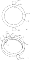
- Figures 1 and 2 show a holder 10, comprising a pot-shaped lower part that is open on the bottom side and an upper part 14, or cover, which is connectable thereto, for instance through screws, in an annular manner, to accommodate a disc-shaped blank 16 and to fix it so that it can be processed in a processing machine such as a milling machine through a CAD/CAM process for the production of a dental part, in particular a full denture.
- a processing machine such as a milling machine through a CAD/CAM process for the production of a dental part, in particular a full denture.
- an adapter 18 also referred to as a positioning aid, is used according to the invention.
- the adapter 18 brings about a positive connection between the blank 16 and the holder 10, so that the desired exact positioning and repositioning is ensured.
- the adapter 18 for instance made from PMMA, is designed in such a way that fixing in the holder 10 takes place by using an existing structural feature of the holder such as a recess or projection, so that changes to the holder itself are not required.
- the holder 10 described in the example consists of the lower part 12 which has a circumferential wall 20 that follows a hollow cylinder section from which diametrically opposite shaft stumps 22, 24, referred to as axes, project, which are used for attachment in a processing machine - hereinafter simply referred to as a milling machine.
- a substantially circumferential and inwardly-projecting web or flange 26 extends from the circumferential wall 20, onto which the blank 16 with a peripherally extending web or collar 28 is placed, which can be an integral component of the blank 16 itself or a separate element, which is connected to the blank 16, for instance through gluing.
- a recess 32 extends over the height of the circumferential wall 20 in the inner wall 30 of the circumferential wall 20 and is suitable for the insertion of an insert, not shown, into the lower part 12 of the holder 10, which can serve for example to hold individual blanks, as is known, for example, from WO 2016/153986 A1 .
- the recess 32 in the lower part 12 is provided for structural reasons.
- this recess 32 or another suitable structural design of the lower part 12 is used to positively hold the adapter 18 or a section thereof so that it is clearly positioned.
- a further section of the adapter 18 engages in a mechanical referencing device 34 to be formed in the blank 16, which in the example is designed as a groove extending in the axial direction of the blank 16.
- the adapter has an arcuate base section 36, which is adapted in the circumferential direction to the recess 32 and with respect to its boundaries 38, 40.
- the back surface 37 of the base portion 36 is adapted in its course to the base surface 39 of the recess 32.
- the distance between the side edges 42, 44 of the base part 36 corresponds to the distance between the edges 38, 40 of the recess 32.
- a projection 46 protrudes from the inner surface of the base part 36, the groove 36 of which is matched to the geometry so that the distance between the side edges 48, 50 of the projection 46 is equal to the distance of the side edges 52, 54 of the groove 34.
- flat-shaped sections 56, 58 in the form of an arc extend from the inner surface of the base section 36 and merge into the circumferential web or collar 28 on the upper side.
- the projections 56, 58 are not mandatory constructive features of the adapter 18.
- the blank 16 is inserted into the lower part 12 of the holder 10 without a positive connection being effected via the adapter 18. It can be seen from the drawing that the blank 16 can be inserted in virtually any desired position. Thus, it is not possible to ensure a predetermined, defined alignment between the blank 16 and the holder 10 or the lower part 12.
- the blank 16 can only be inserted into the lower part 12 in the position in which the groove 34 is aligned with the projection 46 and can penetrate into the groove 34.
- the blank 16 can be inserted into the holder 10 in a clear position and thus into the lower part 12.
- no other position can be assumed between the blank 16 and the lower part 12 of the holder 10 than that specified by the adapter 18.
- this is closed by means of the annular upper part 14 designated as the cover. In particular, the upper part 14 is screwed into the lower part 12.
- the adapter 18 in Fig. 7 is shown purely by way of example, without thereby limiting the invention.
- the adapter would have to bridge a section of the lower part 12, as will be explained with reference to Figures 11 to 13 .
- FIG. 11 A further embodiment of a holder 110 and an adapter 118 is shown in Figures 11 to 13 to enable a clear positioning and repositioning of a blank 116 in accordance with the teaching of the invention.
- the holder 110 comprises a lower part 112 in which a recess (not shown in the drawing) corresponding to the size of the blank 116 is present in order to provide the possibility that the blank 116 can be machined from both sides in a milling machine.
- the blank 116 is fixed in the holder 110 by means of a top part 114 designated as a clamping ring in the holder 110.
- the blank 116 rests with a circumferentially extending web or collar, as explained with reference to Figures 3 and 4 , on a corresponding shoulder of the lower part 112.
- the clamping ring 114 is fixed with the lower part 112 by means of screws, one of which is indicated by the reference number 115 by way of example only.
- corresponding oblong-shaped holes 117 are provided in the clamping ring 114 and have a clearance which is greater than the diameter of the head of the screw 115 in at least one section and is less than it in at least another section.
- oblong-shaped holes and the bore accessible therefrom are used to positively receive a section of the adapter 118.
- an oblong-shaped hole 119 with the bore 121 is used.
- a base section 136 of the adapter 118 is introduced into the oblong-shaped hole 119.
- the adapter 118 has a cuboid central part 138 with end-rounded sections 140, 142, as shown in the drawing for adaptation to the oblong-shaped hole 119.
- the base section 136 must be geometrically adapted to the geometry of the oblong-shaped hole 119 in such a way that movement is prevented in the radial direction of the clamping ring 114. In the longitudinal direction of the oblong-shaped hole 119 this is prevented by the fact that a pin-shaped projection 148, which is adapted to the internal geometry of the bore 121, protrudes from the base section 136.
- the projection 148 is adapted to the bore 121 in such a way that there is a positive engagement preventing, in principle, a relative movement.
- a cuboid projection 146 protrudes from the opposing flat side 150 of the base section 136, to which a mechanical referencing introduced in the blank 116 is adapted in the form of a groove 134 at least in sections so that a positive engagement of the projection 146 into the groove 134 is made possible.
- the adapter 118 is not inserted so that, as a result, the blank 116 can be fixed in any desired orientation to the holder 110. This possibility no longer exists if the adapter 118 on the one hand positively engages with the projection 148 into the bore 121 which is provided with an internal thread and, on the other hand, positively engages in the groove 134 with the projection 146.
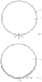
- an implant blank 216 which can have a geometry which is the same as that of the blank 16.
- the implant blank has bores, some of which are identified by the reference numbers 218, 220 by way of example.
- the bores 218, 220 are geometrically adapted to the outer geometry of base elements of abutments. This is preferably a titanium base, on which a ceramic post is placed to form the abutment.
- the blank 216 is made from the corresponding material of the post, in particular zirconium dioxide.
- FIG. 14 An enlarged view of a section of the blank 216 is shown in the lower view in Fig. 14 .
- the blank 216 is provided with a mechanical referencing such as groove 234, as shown in the upper view in Fig. 14 .
- a mechanical referencing such as groove 234, as shown in the upper view in Fig. 14 .
Description
- The invention relates to a method for positioning a blank, in particular a disc-shaped one, which, after being inserted into a holder, is in contact therewith, wherein the holder and an element connected to it in a fixed position has a structural element, such as a receptacle, a recess or a projection.
- In particular, the invention relates to a method for producing a prosthesis, in particular a full denture or an implant abutment, comprising at least the method steps
- Positioning of a blank, in particular a disc-shaped one, in a holder,
- Working of the blank in a processing machine,
- Removal of the blank from the holder and performing at least one working step outside of the processing machine,
- Repositioning of the blank in the holder,
- Resume processing of the blank in the processing machine.
- Examples of processing steps include the securing of artificial teeth in the machined blank, in the case of the production of a full prosthesis, or the production of parts of an abutment.
- Ceramic materials are widely used for the production of dental reconstructions. In this process, blanks are generally machined from the material in a pre-sintered or densely sintered state. For this purpose, it is necessary for the blanks to be fixed in a holder, e.g., through clamping, which in turn is arranged in a processing machine such as a milling machine.
- In order to fix the blank in a processing machine, an adapter is provided according to
WO02/17815 A1 - Corresponding assemblies are given in
EP 0 160 797 B1EP 2 036 516 B1 . -
DE 203 16 004 U1 discloses a metallic blank for the production of a dental prosthesis. The blank has a circumferential groove as well as a notch extending perpendicularly thereto, so that a reproducible clamping can take place in a digitally-controlled dental milling system. The prior art document D1,EP 3 095 412 A2 , relates to a blank for producing a dental element (eg a dental model or a dental replacement part) having a first side, a second side and at least one main holding surface spaced from the second side for holding the blank on a holding device, wherein the blank has a standard holding thickness between the main holding surface and the rear side. - In the production of certain tooth replacement parts, in particular of full prostheses or of implant abutments or parts thereof, it is necessary for the blank to be removed from the holder between individual processing steps. This brings the risk that, during repositioning, i.e., re-insertion into the holder, the blank is not in the same position as in the preceding machining step, so that defective tooth replacement parts are produced.
- The object of the present invention is to further develop a method of the aforementioned type in such a way that, without changes to the holder and an element in fixed-position connection therewith, it is insured that the blank is always in the desired position in the holder and thus relative to the processing machine, so that machining errors resulting from incorrect positioning of the blank are avoided.
- To achieve this aim, the invention essentially provides for the blank to be positioned in the holder by means of an adapter, which is inserted into the holder and the structural element as well as into the blank, the adapter being positively engaged both in the holder or the structural element and in the blank.
- In accordance with the invention, an unambiguous positioning of the blank in the holder is facilitated by a separately produced adapter. In this case, the adapter is inserted into a structure which is present in the holder and in an element that is connected thereto in a fixed position, such as a receptacle like a depression, on the one hand, and in a receptacle adapted to a section of the adapter in the blank to insure a fixed-position relationship between the holder and the blank. The receptacle can also be designed as a projection which is surrounded by the adapter at least in sections.
- Corresponding structures which are suitable for accommodating or fixing a section of the adapter are present in the holders that are available on the market. Such structures may also be formed as bores into which, a screw element is inserted e.g. for fixing an element which closes a holder, such as a cover. To position the blank, the screw is removed and a correspondingly adapted section of the adapter is positively inserted into the bore. A further section of the adapter then engages in the previously formed mechanical referencing, such as a groove, depression or the like, of the blank.
- According to the invention, a separate adapter is used to enable an unambiguous positioning of the blank. There is no need for a holder comprising an integrated structural section, such as a projection, to bring about the desired positioning of the blank in the holder; as an unambiguous positioning is in principle only necessary if a repositioning is required. In contrast, if the holder were to have a projection serving as a positioning aid, then only blanks which have a correspondingly adapted section could be used. According to the teaching of the invention, however, only those blanks that are to be repositioned need to be provided with a mechanical referencing.
- The adapter, which can also be referred to as an auxiliary part, can be produced from thermoplastic material such as PMMA, in particular in the processing machine in which the blank itself is machined. For this purpose it is only necessary that the geometries of the structure, such as the receptacle in the blank holder and the referencing to be produced, are available, e.g., in the form of STL files. Naturally, it is also possible to use prefabricated adapters from other materials, e.g., metallic ones.
- The receptacle for the adapter in the holder respectively the element requires no connection to the contact surface of the blank in the holder. Rather, the adapter may, for example, have a shape for enveloping or bridging regions of the holder, and sections engaging positively in the holder or in the receptacle, that is the mechanical referencing of the blank.
- The teaching according to the invention, i.e., the use of a separately produced adapter, which can be releasably inserted into the holder as well as into the blank and which can also be removed before machining of the blank, is suitable for all types of holders, therefore also for those that circumscribe the blank or envelop it only in part.
- The present invention discloses a method for positioning a disc-shaped blank and a method for producing a prosthesis, in particular a full denture, as defined in the claims.
- Further details, advantages and features of the invention are derived not only from the claims, and the features to be taken from them - either alone and/or in combination - but also from the examples described below and illustrated by drawings.
-
- Fig. 1
- A top view of a lower part of a first embodiment of a holder to hold a blank,
- Fig. 2
- A perspective view of the lower part according to
Fig. 1 , - Fig. 3
- A top view of a blank,
- Fig. 4
- A perspective view of the blank according to
Fig. 3 , - Fig. 5
- A top view of the lower part of the holder according to
Figures 1 and 2 with the blank inserted, - Fig. 6
- A perspective view of the lower part with blank according to
Fig. 5 , - Fig. 7
- Various views of a first embodiment of an adapter,
- Fig. 8
- The lower part of the holder according to
Figures 1 and 2 in which the blank according toFigures 2 and3 is positioned by means of the adapter according toFig. 7 , - Fig. 9
- A perspective view of the arrangement according to
Fig. 8 , - Fig. 10
- A holder with the lower part shown in
Figures 1 and 2 and the locking part connected thereto, - Fig. 11
- A second embodiment of a holder,
- Fig. 12
- The holder according to
Fig. 1 with positioned blank, - Fig. 13
- A further embodiment of an adapter and
- Fig. 14
- Implant blanks.
-
Figures 1 and 2 show aholder 10, comprising a pot-shaped lower part that is open on the bottom side and anupper part 14, or cover, which is connectable thereto, for instance through screws, in an annular manner, to accommodate a disc-shaped blank 16 and to fix it so that it can be processed in a processing machine such as a milling machine through a CAD/CAM process for the production of a dental part, in particular a full denture. - To make certain that the blank 16, which may be, for example, of plastic such as PMMA or a ceramic, such as zirconium dioxide, when it has to be removed from the processing machine and thus from the
holder 10 between individual processing steps, in particular in connection with the production of a full denture or parts of abutments, upon re-inserting, i.e., repositioning, assumes exactly that position prior to removal, anadapter 18, also referred to as a positioning aid, is used according to the invention. Theadapter 18 brings about a positive connection between the blank 16 and theholder 10, so that the desired exact positioning and repositioning is ensured. - The
adapter 18, for instance made from PMMA, is designed in such a way that fixing in theholder 10 takes place by using an existing structural feature of the holder such as a recess or projection, so that changes to the holder itself are not required. - The
holder 10 described in the example consists of thelower part 12 which has acircumferential wall 20 that follows a hollow cylinder section from which diametricallyopposite shaft stumps flange 26 extends from thecircumferential wall 20, onto which the blank 16 with a peripherally extending web orcollar 28 is placed, which can be an integral component of the blank 16 itself or a separate element, which is connected to the blank 16, for instance through gluing. - In the example, a
recess 32 extends over the height of thecircumferential wall 20 in theinner wall 30 of thecircumferential wall 20 and is suitable for the insertion of an insert, not shown, into thelower part 12 of theholder 10, which can serve for example to hold individual blanks, as is known, for example, fromWO 2016/153986 A1 . - In other words, the
recess 32 in thelower part 12 is provided for structural reasons. According to the invention, thisrecess 32 or another suitable structural design of thelower part 12 is used to positively hold theadapter 18 or a section thereof so that it is clearly positioned. A further section of theadapter 18 engages in a mechanical referencingdevice 34 to be formed in the blank 16, which in the example is designed as a groove extending in the axial direction of the blank 16. - As the graphical representation of
Fig. 7 shows, the adapter has anarcuate base section 36, which is adapted in the circumferential direction to therecess 32 and with respect to itsboundaries back surface 37 of thebase portion 36 is adapted in its course to thebase surface 39 of therecess 32. Thus, theadapter 18 can be positively inserted into therecess 32 without a displacement of theadapter 18 in the direction of the circumferential wall. - Thus, the distance between the side edges 42, 44 of the
base part 36 corresponds to the distance between theedges recess 32. - A
projection 46 protrudes from the inner surface of thebase part 36, thegroove 36 of which is matched to the geometry so that the distance between the side edges 48, 50 of theprojection 46 is equal to the distance of the side edges 52, 54 of thegroove 34. - Furthermore, flat-shaped
sections base section 36 and merge into the circumferential web orcollar 28 on the upper side. However, theprojections adapter 18. - In
Figures 5 and 6 , the blank 16 is inserted into thelower part 12 of theholder 10 without a positive connection being effected via theadapter 18. It can be seen from the drawing that the blank 16 can be inserted in virtually any desired position. Thus, it is not possible to ensure a predetermined, defined alignment between the blank 16 and theholder 10 or thelower part 12. - If the
adapter 18 is used as shown in the drawings ofFigures 8 and 9 , then the blank 16 can only be inserted into thelower part 12 in the position in which thegroove 34 is aligned with theprojection 46 and can penetrate into thegroove 34. Thus, the blank 16 can be inserted into theholder 10 in a clear position and thus into thelower part 12. After removal and subsequent repositioning, no other position can be assumed between the blank 16 and thelower part 12 of theholder 10 than that specified by theadapter 18. After correct positioning of the blank 16 in thelower part 12, this is closed by means of the annularupper part 14 designated as the cover. In particular, theupper part 14 is screwed into thelower part 12. - The
adapter 18 inFig. 7 is shown purely by way of example, without thereby limiting the invention. There is also the possibility, for example if a recess is provided in theupper edge 60 of theupper part 12, to form an adapter which can be inserted into the corresponding recess and, on the other hand, into a mechanical referencing such as a bore or groove present in the blank 16. In this case, the adapter would have to bridge a section of thelower part 12, as will be explained with reference toFigures 11 to 13 . - Other structured regions which are present in a holder can also be used to enable a form-fitting reception of an adapter which, in accordance with the teaching of the invention, must in turn positively engage a mechanical referencing of a blank to achieve a positioning and repositioning of the blank in a desired manner in the corresponding holder, without the possibility of any deviation in the position of the blank relative to the holder after re-insertion.
- A further embodiment of a
holder 110 and anadapter 118 is shown inFigures 11 to 13 to enable a clear positioning and repositioning of a blank 116 in accordance with the teaching of the invention. - The
holder 110 comprises alower part 112 in which a recess (not shown in the drawing) corresponding to the size of the blank 116 is present in order to provide the possibility that the blank 116 can be machined from both sides in a milling machine. - The blank 116 is fixed in the
holder 110 by means of atop part 114 designated as a clamping ring in theholder 110. In this case, the blank 116 rests with a circumferentially extending web or collar, as explained with reference toFigures 3 and 4 , on a corresponding shoulder of thelower part 112. - The
clamping ring 114 is fixed with thelower part 112 by means of screws, one of which is indicated by thereference number 115 by way of example only. In order to allow theclamping ring 114 to be easily connected to, or disconnected from, thelower part 112 without having to remove thescrew 115, corresponding oblong-shapedholes 117 are provided in theclamping ring 114 and have a clearance which is greater than the diameter of the head of thescrew 115 in at least one section and is less than it in at least another section. - One of these oblong-shaped holes and the bore accessible therefrom are used to positively receive a section of the
adapter 118. In the example ofFig. 11 , an oblong-shapedhole 119 with thebore 121 is used. For this purpose, it is naturally necessary to first remove the screw required for fixing theclamping ring 114. - A
base section 136 of theadapter 118 is introduced into the oblong-shapedhole 119. For this purpose, and without limiting the inventive teaching, theadapter 118 has a cuboidcentral part 138 with end-roundedsections hole 119. In fact, thebase section 136 must be geometrically adapted to the geometry of the oblong-shapedhole 119 in such a way that movement is prevented in the radial direction of theclamping ring 114. In the longitudinal direction of the oblong-shapedhole 119 this is prevented by the fact that a pin-shapedprojection 148, which is adapted to the internal geometry of thebore 121, protrudes from thebase section 136. Theprojection 148 is adapted to thebore 121 in such a way that there is a positive engagement preventing, in principle, a relative movement. Acuboid projection 146 protrudes from the opposingflat side 150 of thebase section 136, to which a mechanical referencing introduced in the blank 116 is adapted in the form of agroove 134 at least in sections so that a positive engagement of theprojection 146 into thegroove 134 is made possible. The result is that when theadapter 118 is inserted, this ensures a clear orientation of the blank 116 relative to theholder 110, i.e., repositioning can take place without a change in the position from that before the removal of the blank 116 from theholder 110. - The geometry of the
adapter 118 is evident from the diagram inFig. 13 , without the need for further descriptions. - In
Fig. 11 , theadapter 118 is not inserted so that, as a result, the blank 116 can be fixed in any desired orientation to theholder 110. This possibility no longer exists if theadapter 118 on the one hand positively engages with theprojection 148 into thebore 121 which is provided with an internal thread and, on the other hand, positively engages in thegroove 134 with theprojection 146. - It can also be seen that the
projection 146, which engages positively in sections with thegroove 134, bridges theclamping ring 114. This is also illustrated inFig. 12 . - In the middle view of
Fig. 14 , animplant blank 216 is shown which can have a geometry which is the same as that of the blank 16. In a departure from the blank 16, the implant blank has bores, some of which are identified by thereference numbers bores - An enlarged view of a section of the blank 216 is shown in the lower view in
Fig. 14 . - According to the teaching of the invention, the blank 216 is provided with a mechanical referencing such as
groove 234, as shown in the upper view inFig. 14 . This insures that an unambiguous repositioning is made possible in a holder in which the groove positively receives a section of an adapter, which is in turn positively connected to a holder (not shown).
Claims (5)
- A method for positioning a disc-shaped blank (16, 116, 216), which after insertion in a holder is in contact therewith, wherein the holder (10, 110) has a structural element (32, 119, 121) such as a recess, such as a depression or a projection, wherein the blank (16, 116, 216) is positioned in the holder (10, 110) by means of an adapter (18, 118), which is inserted in both the holder (10, 110) and the structural element (32, 119, 121),and the blank (16, 116, 216), wherein the adapter positively engages with the holder (10, 110) and the structural element (32, 119, 121), and with the blank (16, 116, 216);wherein the blank (16, 116, 216) after positioning in the holder (10, 110) is processed, removed from the holder and then repositioned in the holder by means of the adapter (18, 118);wherein the blank (16, 116, 216) is provided with a mechanical referencing (34, 134), such as a recess, such as a groove, which interacts with a first section (46, 146) of the adapter (18, 118) for positioning of the blank, the first section (46, 146) penetrates into the mechanical referencing;and wherein for unambiguous positioning of the blank (16, 116, 216) the adapter (18, 118) with a second section (36, 136) interacts with the structural element (34, 119, 121) and with the first section (46, 146) interacts with the mechanical referencing (34, 134) of the blank, wherein between the first section and the second section a section of the adapter (18, 118) bridges over a section of the holder (10, 110).
- The method according to claim 1,
characterized in that
the holder (10, 110) contacts the blank (16, 116, 216) without projection. - The method for the production of a prosthesis, in particular a full denture, comprising at least the following steps- Positioning of a disc shaped blank (16, 116, 216), in a holder (10, 110),- Processing of the blank in a processing machine,- Removal of the blank from the holder and working of the blank outside of the processing machine,- Repositioning of the blank in the holder,- Repeat processing of the blank in the processing machine,characterized in that
both the positioning and repositioning of the blank (16, 116, 216) in the holder (10, 110) is by means of an adapter (18, 118) which interacts both with the holder or a fixed-position element connected to the holder and with a mechanical referencing (34, 134) formed in the blank and adapted to a section of the adapter. - The method according to at least one of the above claims,
characterized in that
the blank (16, 116, 216) is such that its circumferential surface or a section of the circumferential surface or an element that is connected to the blank or formed integrally with it, such as a collar (28), is in contact preferably circumferentially or substantially circumferentially with the holder that abuts the circumferential surface respectively the section. - The method according to at least one of the above claims,
characterized in that
the blank (16, 116, 216) is one from which a dental prosthesis or sections of an abutment can be produced.
Applications Claiming Priority (1)
| Application Number | Priority Date | Filing Date | Title |
|---|---|---|---|
| PCT/EP2017/070003 WO2019029791A1 (en) | 2017-08-08 | 2017-08-08 | Method for the positioning of a blank |
Publications (2)
| Publication Number | Publication Date |
|---|---|
| EP3664744A1 EP3664744A1 (en) | 2020-06-17 |
| EP3664744B1 true EP3664744B1 (en) | 2023-03-08 |
Family
ID=59631755
Family Applications (1)
| Application Number | Title | Priority Date | Filing Date |
|---|---|---|---|
| EP17752353.7A Active EP3664744B1 (en) | 2017-08-08 | 2017-08-08 | Method for the positioning of a blank |
Country Status (5)
| Country | Link |
|---|---|
| EP (1) | EP3664744B1 (en) |
| JP (1) | JP7035165B2 (en) |
| CA (1) | CA3072372C (en) |
| ES (1) | ES2942852T3 (en) |
| WO (1) | WO2019029791A1 (en) |
Families Citing this family (2)
| Publication number | Priority date | Publication date | Assignee | Title |
|---|---|---|---|---|
| US10959817B2 (en) | 2019-08-14 | 2021-03-30 | Sdc U.S. Smilepay Spv | Dental model holding system |
| CN111444611B (en) * | 2020-03-25 | 2023-04-07 | 东风汽车集团有限公司 | Numbering and digital modeling establishing method for blank based on ENOVIA |
Citations (1)
| Publication number | Priority date | Publication date | Assignee | Title |
|---|---|---|---|---|
| EP3372192A1 (en) * | 2017-03-10 | 2018-09-12 | Johannes Petrus Michael Grobbee | Dental blank positioning device |
Family Cites Families (8)
| Publication number | Priority date | Publication date | Assignee | Title |
|---|---|---|---|---|
| CH665551A5 (en) | 1984-03-06 | 1988-05-31 | Werner Hans Dr Med De Moermann | BLANK FOR THE MANUFACTURE OF DENTAL TECHNOLOGY MOLDED PARTS. |
| US6482284B1 (en) | 2000-08-31 | 2002-11-19 | 3M Innovative Properties Company | Method of making a dental mill blank and support stub assembly |
| DE20316004U1 (en) | 2003-10-14 | 2004-03-04 | Stührenberg, Birgit | Metallic blank for the production of a denture in a digitally-controlled dental cutting system, has the shape of a flat circular disk which is provided with a peripheral groove and a notch running parallel to its axis |
| DE102007043837B4 (en) | 2007-09-14 | 2014-02-13 | Ivoclar Vivadent Ag | blank arrangement |
| DE202012008015U1 (en) * | 2012-08-23 | 2012-12-12 | Doceram Gmbh | Holder for blanks |
| DE102014117109A1 (en) * | 2014-11-21 | 2016-05-25 | Merz Dental Gmbh | Method for positional positioning of a semifinished product, method for producing a semifinished product for reproducible positional positioning and a suitable semi-finished product and a corresponding use thereof |
| US10010386B2 (en) | 2015-03-24 | 2018-07-03 | Ivoclar Vivadent Ag | Dental blank holder |
| AT516840B1 (en) * | 2015-04-30 | 2016-09-15 | Steger Heinrich | Blank for the production of a dental element |
-
2017
- 2017-08-08 JP JP2020507105A patent/JP7035165B2/en active Active
- 2017-08-08 CA CA3072372A patent/CA3072372C/en active Active
- 2017-08-08 WO PCT/EP2017/070003 patent/WO2019029791A1/en unknown
- 2017-08-08 EP EP17752353.7A patent/EP3664744B1/en active Active
- 2017-08-08 ES ES17752353T patent/ES2942852T3/en active Active
Patent Citations (1)
| Publication number | Priority date | Publication date | Assignee | Title |
|---|---|---|---|---|
| EP3372192A1 (en) * | 2017-03-10 | 2018-09-12 | Johannes Petrus Michael Grobbee | Dental blank positioning device |
Also Published As
| Publication number | Publication date |
|---|---|
| WO2019029791A1 (en) | 2019-02-14 |
| EP3664744A1 (en) | 2020-06-17 |
| JP2020531069A (en) | 2020-11-05 |
| JP7035165B2 (en) | 2022-03-14 |
| CA3072372A1 (en) | 2019-02-14 |
| ES2942852T3 (en) | 2023-06-07 |
| CA3072372C (en) | 2023-06-27 |
Similar Documents
| Publication | Publication Date | Title |
|---|---|---|
| US10799326B2 (en) | Method for the positioning of a blank | |
| EP3380036B1 (en) | Plate for production of a dental implant and/or artificial prosthesis | |
| DK2525737T3 (en) | Abutment for a dental implant and combination of abutment and implant | |
| US8622377B2 (en) | Holder for CAD/CAM blanks | |
| US7789601B2 (en) | Mill blank mandrel | |
| EP3117794B1 (en) | Dental implant prosthetic structure | |
| US20100000677A1 (en) | Device for producing a dental workpiece | |
| EP3664744B1 (en) | Method for the positioning of a blank | |
| KR20140018884A (en) | Denture system | |
| US11224919B2 (en) | Method for correcting an axial position of a workpiece support | |
| US20080254413A1 (en) | Process for the production of a head piece of a tooth implant and manufacturing kit for such a process | |
| US20180353269A1 (en) | Interface element for dental prostheses | |
| US20150099243A1 (en) | Axially elongate dental machining portion | |
| US20170056134A1 (en) | Dental abutments and associated systems and methods | |
| EP3868332A1 (en) | Milling adaptor | |
| EP3641695A1 (en) | Mounting element for production of a dental prosthesis, a prosthesis and method of manufacturing same | |
| US11839941B2 (en) | Holding device for an abutment blank | |
| JP2007222225A (en) | Connector and method of making dental prosthesis by using it | |
| CN112689484A (en) | Blank for producing a dental prosthesis and method for producing the same | |
| KR101249515B1 (en) | A material for abutment and a processing method using the same |
Legal Events
| Date | Code | Title | Description |
|---|---|---|---|
| STAA | Information on the status of an ep patent application or granted ep patent |
Free format text: STATUS: UNKNOWN |
|
| STAA | Information on the status of an ep patent application or granted ep patent |
Free format text: STATUS: THE INTERNATIONAL PUBLICATION HAS BEEN MADE |
|
| PUAI | Public reference made under article 153(3) epc to a published international application that has entered the european phase |
Free format text: ORIGINAL CODE: 0009012 |
|
| STAA | Information on the status of an ep patent application or granted ep patent |
Free format text: STATUS: REQUEST FOR EXAMINATION WAS MADE |
|
| 17P | Request for examination filed |
Effective date: 20200213 |
|
| AK | Designated contracting states |
Kind code of ref document: A1 Designated state(s): AL AT BE BG CH CY CZ DE DK EE ES FI FR GB GR HR HU IE IS IT LI LT LU LV MC MK MT NL NO PL PT RO RS SE SI SK SM TR |
|
| AX | Request for extension of the european patent |
Extension state: BA ME |
|
| RIN1 | Information on inventor provided before grant (corrected) |
Inventor name: GEBHARDT, ANDREAS Inventor name: VOELKL, LOTHAR Inventor name: FECHER, STEFAN |
|
| DAV | Request for validation of the european patent (deleted) | ||
| DAX | Request for extension of the european patent (deleted) | ||
| STAA | Information on the status of an ep patent application or granted ep patent |
Free format text: STATUS: EXAMINATION IS IN PROGRESS |
|
| 17Q | First examination report despatched |
Effective date: 20210503 |
|
| STAA | Information on the status of an ep patent application or granted ep patent |
Free format text: STATUS: EXAMINATION IS IN PROGRESS |
|
| REG | Reference to a national code |
Ref country code: DE Ref legal event code: R079 Ref document number: 602017066632 Country of ref document: DE Free format text: PREVIOUS MAIN CLASS: A61C0013000000 Ipc: B23Q0003000000 |
|
| GRAP | Despatch of communication of intention to grant a patent |
Free format text: ORIGINAL CODE: EPIDOSNIGR1 |
|
| STAA | Information on the status of an ep patent application or granted ep patent |
Free format text: STATUS: GRANT OF PATENT IS INTENDED |
|
| RIC1 | Information provided on ipc code assigned before grant |
Ipc: B23Q 3/00 20060101AFI20220901BHEP |
|
| INTG | Intention to grant announced |
Effective date: 20221005 |
|
| GRAS | Grant fee paid |
Free format text: ORIGINAL CODE: EPIDOSNIGR3 |
|
| GRAA | (expected) grant |
Free format text: ORIGINAL CODE: 0009210 |
|
| STAA | Information on the status of an ep patent application or granted ep patent |
Free format text: STATUS: THE PATENT HAS BEEN GRANTED |
|
| AK | Designated contracting states |
Kind code of ref document: B1 Designated state(s): AL AT BE BG CH CY CZ DE DK EE ES FI FR GB GR HR HU IE IS IT LI LT LU LV MC MK MT NL NO PL PT RO RS SE SI SK SM TR |
|
| REG | Reference to a national code |
Ref country code: GB Ref legal event code: FG4D |
|
| REG | Reference to a national code |
Ref country code: CH Ref legal event code: EP Ref country code: AT Ref legal event code: REF Ref document number: 1552259 Country of ref document: AT Kind code of ref document: T Effective date: 20230315 |
|
| REG | Reference to a national code |
Ref country code: DE Ref legal event code: R096 Ref document number: 602017066632 Country of ref document: DE |
|
| REG | Reference to a national code |
Ref country code: IE Ref legal event code: FG4D |
|
| REG | Reference to a national code |
Ref country code: NL Ref legal event code: FP |
|
| REG | Reference to a national code |
Ref country code: ES Ref legal event code: FG2A Ref document number: 2942852 Country of ref document: ES Kind code of ref document: T3 Effective date: 20230607 |
|
| P01 | Opt-out of the competence of the unified patent court (upc) registered |
Effective date: 20230509 |
|
| REG | Reference to a national code |
Ref country code: LT Ref legal event code: MG9D |
|
| PG25 | Lapsed in a contracting state [announced via postgrant information from national office to epo] |
Ref country code: RS Free format text: LAPSE BECAUSE OF FAILURE TO SUBMIT A TRANSLATION OF THE DESCRIPTION OR TO PAY THE FEE WITHIN THE PRESCRIBED TIME-LIMIT Effective date: 20230308 Ref country code: NO Free format text: LAPSE BECAUSE OF FAILURE TO SUBMIT A TRANSLATION OF THE DESCRIPTION OR TO PAY THE FEE WITHIN THE PRESCRIBED TIME-LIMIT Effective date: 20230608 Ref country code: LV Free format text: LAPSE BECAUSE OF FAILURE TO SUBMIT A TRANSLATION OF THE DESCRIPTION OR TO PAY THE FEE WITHIN THE PRESCRIBED TIME-LIMIT Effective date: 20230308 Ref country code: LT Free format text: LAPSE BECAUSE OF FAILURE TO SUBMIT A TRANSLATION OF THE DESCRIPTION OR TO PAY THE FEE WITHIN THE PRESCRIBED TIME-LIMIT Effective date: 20230308 Ref country code: HR Free format text: LAPSE BECAUSE OF FAILURE TO SUBMIT A TRANSLATION OF THE DESCRIPTION OR TO PAY THE FEE WITHIN THE PRESCRIBED TIME-LIMIT Effective date: 20230308 |
|
| PG25 | Lapsed in a contracting state [announced via postgrant information from national office to epo] |
Ref country code: SE Free format text: LAPSE BECAUSE OF FAILURE TO SUBMIT A TRANSLATION OF THE DESCRIPTION OR TO PAY THE FEE WITHIN THE PRESCRIBED TIME-LIMIT Effective date: 20230308 Ref country code: GR Free format text: LAPSE BECAUSE OF FAILURE TO SUBMIT A TRANSLATION OF THE DESCRIPTION OR TO PAY THE FEE WITHIN THE PRESCRIBED TIME-LIMIT Effective date: 20230609 Ref country code: FI Free format text: LAPSE BECAUSE OF FAILURE TO SUBMIT A TRANSLATION OF THE DESCRIPTION OR TO PAY THE FEE WITHIN THE PRESCRIBED TIME-LIMIT Effective date: 20230308 |
|
| PGFP | Annual fee paid to national office [announced via postgrant information from national office to epo] |
Ref country code: NL Payment date: 20230718 Year of fee payment: 7 |
|
| PG25 | Lapsed in a contracting state [announced via postgrant information from national office to epo] |
Ref country code: SM Free format text: LAPSE BECAUSE OF FAILURE TO SUBMIT A TRANSLATION OF THE DESCRIPTION OR TO PAY THE FEE WITHIN THE PRESCRIBED TIME-LIMIT Effective date: 20230308 Ref country code: RO Free format text: LAPSE BECAUSE OF FAILURE TO SUBMIT A TRANSLATION OF THE DESCRIPTION OR TO PAY THE FEE WITHIN THE PRESCRIBED TIME-LIMIT Effective date: 20230308 Ref country code: PT Free format text: LAPSE BECAUSE OF FAILURE TO SUBMIT A TRANSLATION OF THE DESCRIPTION OR TO PAY THE FEE WITHIN THE PRESCRIBED TIME-LIMIT Effective date: 20230710 Ref country code: EE Free format text: LAPSE BECAUSE OF FAILURE TO SUBMIT A TRANSLATION OF THE DESCRIPTION OR TO PAY THE FEE WITHIN THE PRESCRIBED TIME-LIMIT Effective date: 20230308 Ref country code: CZ Free format text: LAPSE BECAUSE OF FAILURE TO SUBMIT A TRANSLATION OF THE DESCRIPTION OR TO PAY THE FEE WITHIN THE PRESCRIBED TIME-LIMIT Effective date: 20230308 |
|
| PGFP | Annual fee paid to national office [announced via postgrant information from national office to epo] |
Ref country code: IT Payment date: 20230711 Year of fee payment: 7 Ref country code: ES Payment date: 20230907 Year of fee payment: 7 Ref country code: CH Payment date: 20230901 Year of fee payment: 7 Ref country code: AT Payment date: 20230725 Year of fee payment: 7 |
|
| PG25 | Lapsed in a contracting state [announced via postgrant information from national office to epo] |
Ref country code: SK Free format text: LAPSE BECAUSE OF FAILURE TO SUBMIT A TRANSLATION OF THE DESCRIPTION OR TO PAY THE FEE WITHIN THE PRESCRIBED TIME-LIMIT Effective date: 20230308 Ref country code: PL Free format text: LAPSE BECAUSE OF FAILURE TO SUBMIT A TRANSLATION OF THE DESCRIPTION OR TO PAY THE FEE WITHIN THE PRESCRIBED TIME-LIMIT Effective date: 20230308 Ref country code: IS Free format text: LAPSE BECAUSE OF FAILURE TO SUBMIT A TRANSLATION OF THE DESCRIPTION OR TO PAY THE FEE WITHIN THE PRESCRIBED TIME-LIMIT Effective date: 20230708 |
|
| PGFP | Annual fee paid to national office [announced via postgrant information from national office to epo] |
Ref country code: FR Payment date: 20230703 Year of fee payment: 7 Ref country code: DE Payment date: 20230703 Year of fee payment: 7 |
|
| REG | Reference to a national code |
Ref country code: DE Ref legal event code: R097 Ref document number: 602017066632 Country of ref document: DE |
|
| PLBE | No opposition filed within time limit |
Free format text: ORIGINAL CODE: 0009261 |
|
| STAA | Information on the status of an ep patent application or granted ep patent |
Free format text: STATUS: NO OPPOSITION FILED WITHIN TIME LIMIT |
|
| PG25 | Lapsed in a contracting state [announced via postgrant information from national office to epo] |
Ref country code: SI Free format text: LAPSE BECAUSE OF FAILURE TO SUBMIT A TRANSLATION OF THE DESCRIPTION OR TO PAY THE FEE WITHIN THE PRESCRIBED TIME-LIMIT Effective date: 20230308 Ref country code: DK Free format text: LAPSE BECAUSE OF FAILURE TO SUBMIT A TRANSLATION OF THE DESCRIPTION OR TO PAY THE FEE WITHIN THE PRESCRIBED TIME-LIMIT Effective date: 20230308 |
|
| 26N | No opposition filed |
Effective date: 20231211 |
|
| REG | Reference to a national code |
Ref country code: AT Ref legal event code: UEP Ref document number: 1552259 Country of ref document: AT Kind code of ref document: T Effective date: 20230308 |
|
| PG25 | Lapsed in a contracting state [announced via postgrant information from national office to epo] |
Ref country code: MC Free format text: LAPSE BECAUSE OF FAILURE TO SUBMIT A TRANSLATION OF THE DESCRIPTION OR TO PAY THE FEE WITHIN THE PRESCRIBED TIME-LIMIT Effective date: 20230308 |
|
| PG25 | Lapsed in a contracting state [announced via postgrant information from national office to epo] |
Ref country code: MC Free format text: LAPSE BECAUSE OF FAILURE TO SUBMIT A TRANSLATION OF THE DESCRIPTION OR TO PAY THE FEE WITHIN THE PRESCRIBED TIME-LIMIT Effective date: 20230308 |