EP3664671B1 - Implement for stirring or comminuting food - Google Patents
Implement for stirring or comminuting food Download PDFInfo
- Publication number
- EP3664671B1 EP3664671B1 EP18743428.7A EP18743428A EP3664671B1 EP 3664671 B1 EP3664671 B1 EP 3664671B1 EP 18743428 A EP18743428 A EP 18743428A EP 3664671 B1 EP3664671 B1 EP 3664671B1
- Authority
- EP
- European Patent Office
- Prior art keywords
- assembly
- inner assembly
- outer assembly
- relative
- implement according
- Prior art date
- Legal status (The legal status is an assumption and is not a legal conclusion. Google has not performed a legal analysis and makes no representation as to the accuracy of the status listed.)
- Active
Links
- 235000013305 food Nutrition 0.000 title claims description 20
- 238000003756 stirring Methods 0.000 title claims description 9
- 238000012545 processing Methods 0.000 description 6
- 230000000712 assembly Effects 0.000 description 5
- 238000000429 assembly Methods 0.000 description 5
- 238000006073 displacement reaction Methods 0.000 description 3
- 239000007788 liquid Substances 0.000 description 3
- 230000005540 biological transmission Effects 0.000 description 2
- 238000013461 design Methods 0.000 description 2
- 230000000694 effects Effects 0.000 description 2
- 230000006870 function Effects 0.000 description 2
- 235000021059 hard food Nutrition 0.000 description 2
- 230000007246 mechanism Effects 0.000 description 2
- 238000005096 rolling process Methods 0.000 description 2
- 235000002767 Daucus carota Nutrition 0.000 description 1
- 244000000626 Daucus carota Species 0.000 description 1
- 230000006978 adaptation Effects 0.000 description 1
- 238000013459 approach Methods 0.000 description 1
- 230000008901 benefit Effects 0.000 description 1
- 230000008878 coupling Effects 0.000 description 1
- 238000010168 coupling process Methods 0.000 description 1
- 238000005859 coupling reaction Methods 0.000 description 1
- 230000001419 dependent effect Effects 0.000 description 1
- 230000000881 depressing effect Effects 0.000 description 1
- 239000010794 food waste Substances 0.000 description 1
- 230000001771 impaired effect Effects 0.000 description 1
- 238000007373 indentation Methods 0.000 description 1
- 230000003993 interaction Effects 0.000 description 1
- 238000004898 kneading Methods 0.000 description 1
- 230000005923 long-lasting effect Effects 0.000 description 1
- 238000012423 maintenance Methods 0.000 description 1
- 239000000463 material Substances 0.000 description 1
- 238000000034 method Methods 0.000 description 1
- 238000002360 preparation method Methods 0.000 description 1
- 230000008569 process Effects 0.000 description 1
- 230000000750 progressive effect Effects 0.000 description 1
- 230000009993 protective function Effects 0.000 description 1
- 235000021055 solid food Nutrition 0.000 description 1
- 238000012360 testing method Methods 0.000 description 1
Images


Classifications
-
- A—HUMAN NECESSITIES
- A47—FURNITURE; DOMESTIC ARTICLES OR APPLIANCES; COFFEE MILLS; SPICE MILLS; SUCTION CLEANERS IN GENERAL
- A47J—KITCHEN EQUIPMENT; COFFEE MILLS; SPICE MILLS; APPARATUS FOR MAKING BEVERAGES
- A47J43/00—Implements for preparing or holding food, not provided for in other groups of this subclass
- A47J43/04—Machines for domestic use not covered elsewhere, e.g. for grinding, mixing, stirring, kneading, emulsifying, whipping or beating foodstuffs, e.g. power-driven
- A47J43/07—Parts or details, e.g. mixing tools, whipping tools
- A47J43/0705—Parts or details, e.g. mixing tools, whipping tools for machines with tools driven from the upper side
- A47J43/0711—Parts or details, e.g. mixing tools, whipping tools for machines with tools driven from the upper side mixing, whipping or cutting tools
-
- A—HUMAN NECESSITIES
- A47—FURNITURE; DOMESTIC ARTICLES OR APPLIANCES; COFFEE MILLS; SPICE MILLS; SUCTION CLEANERS IN GENERAL
- A47J—KITCHEN EQUIPMENT; COFFEE MILLS; SPICE MILLS; APPARATUS FOR MAKING BEVERAGES
- A47J43/00—Implements for preparing or holding food, not provided for in other groups of this subclass
- A47J43/04—Machines for domestic use not covered elsewhere, e.g. for grinding, mixing, stirring, kneading, emulsifying, whipping or beating foodstuffs, e.g. power-driven
- A47J43/044—Machines for domestic use not covered elsewhere, e.g. for grinding, mixing, stirring, kneading, emulsifying, whipping or beating foodstuffs, e.g. power-driven with tools driven from the top side
-
- A—HUMAN NECESSITIES
- A47—FURNITURE; DOMESTIC ARTICLES OR APPLIANCES; COFFEE MILLS; SPICE MILLS; SUCTION CLEANERS IN GENERAL
- A47J—KITCHEN EQUIPMENT; COFFEE MILLS; SPICE MILLS; APPARATUS FOR MAKING BEVERAGES
- A47J43/00—Implements for preparing or holding food, not provided for in other groups of this subclass
- A47J43/04—Machines for domestic use not covered elsewhere, e.g. for grinding, mixing, stirring, kneading, emulsifying, whipping or beating foodstuffs, e.g. power-driven
- A47J43/06—Machines for domestic use not covered elsewhere, e.g. for grinding, mixing, stirring, kneading, emulsifying, whipping or beating foodstuffs, e.g. power-driven with a plurality of interchangeable working units, e.g. with a single driving-unit
-
- A—HUMAN NECESSITIES
- A47—FURNITURE; DOMESTIC ARTICLES OR APPLIANCES; COFFEE MILLS; SPICE MILLS; SUCTION CLEANERS IN GENERAL
- A47J—KITCHEN EQUIPMENT; COFFEE MILLS; SPICE MILLS; APPARATUS FOR MAKING BEVERAGES
- A47J43/00—Implements for preparing or holding food, not provided for in other groups of this subclass
- A47J43/04—Machines for domestic use not covered elsewhere, e.g. for grinding, mixing, stirring, kneading, emulsifying, whipping or beating foodstuffs, e.g. power-driven
- A47J43/07—Parts or details, e.g. mixing tools, whipping tools
- A47J43/08—Driving mechanisms
- A47J43/082—Driving mechanisms for machines with tools driven from the upper side
-
- A—HUMAN NECESSITIES
- A47—FURNITURE; DOMESTIC ARTICLES OR APPLIANCES; COFFEE MILLS; SPICE MILLS; SUCTION CLEANERS IN GENERAL
- A47J—KITCHEN EQUIPMENT; COFFEE MILLS; SPICE MILLS; APPARATUS FOR MAKING BEVERAGES
- A47J43/00—Implements for preparing or holding food, not provided for in other groups of this subclass
- A47J43/04—Machines for domestic use not covered elsewhere, e.g. for grinding, mixing, stirring, kneading, emulsifying, whipping or beating foodstuffs, e.g. power-driven
- A47J43/044—Machines for domestic use not covered elsewhere, e.g. for grinding, mixing, stirring, kneading, emulsifying, whipping or beating foodstuffs, e.g. power-driven with tools driven from the top side
- A47J2043/04409—Apparatus of hand held type
- A47J2043/04427—Apparatus of hand held type with housing extending vertically in line with the tool axis
Definitions
- the present invention relates to an implement for stirring or chopping food, such as a hand blender.
- Conventional tools for stirring or chopping food are, for example, from WO 96/10944 A1 or the EP 0 724 857 A1 known. Such tools are used in particular in the daily preparation of food, for example to chop up and mix food.
- One type of work device is hand blender, which has found widespread use in households, but also in professional catering establishments.
- hand mixers typically have a motor housing to which an elongated housing part, the so-called shaft, is connected, which in turn merges at its end into a shield with an end open at the bottom, the so-called bell.
- a drive motor is arranged in the motor housing, which drives a working shaft guided through the shaft, at the end of which a working part, for example a cutting knife in the form of a rapidly rotating blade, is usually attached in the area of the bell, in order to mix liquids and solid foods to shred.
- a working part for example a cutting knife in the form of a rapidly rotating blade
- the shaft usually takes on the adaptation of the motor housing to the shaft assembly and often the axial one as well as radial bearing of the shaft, which is required to drive the knife.
- the bell primarily has a protective function in order to make it more difficult for the user to reach into the blade. It also serves to define a fixed distance between the blade and the bottom of the processing vessel (pot, mixing bowl, etc.), to optimize the flow around the blade and as a splash guard when immersed in liquids.
- the bell is dimensioned so that it completely encloses the cutting knife and, viewed in the direction of the axis of the working shaft, protrudes a certain distance beyond the end of the shaft or the cutting knife.
- the blades are always attached in a defined horizontal position within the bell.
- the blades are firmly mounted on a shaft and are usually rigidly mounted radially and axially. This results in a processing space that can be reached by the knife and that is spatially limited.
- the "normal" up and down movement of the entire hand blender by the operator means that this space is only marginally larger.
- the space below the knife is not reached by it.
- the comminution then usually only takes place through flow effects. Provided that there is enough liquid around the material to be cut, it will be drawn through the processing area with the flow and thus shredded.
- the shaft can repeatedly suck on the bottom of the vessel during operation, which can be extremely annoying for the user, since it requires increased effort to detach the shaft from the bottom again.
- This is mainly due to the position of the cutting knife within the bell, because the geometry of the knife, which is sensible for its function, ensures a "propeller effect" and causes the entire shaft to be sucked into the processing floor.
- a working device for stirring or chopping food has a rotatable shaft driven by a motor, at the end of which a working part is provided opposite the motor.
- a tool can be a hand blender or a hand mixer.
- the motor is typically an electric motor, but it can be any other type of motor.
- the working part provided on the motor can be, for example, a blade, a knife, a stirring tool or a kneading tool (such as a stirring rod).
- this can be any type of work part, which can be used in the processing of foodstuffs and which is used for this purpose in a rotating or rotating oscillating manner.
- the implement has an inner and an outer assembly which at least partially define a housing (“shaft”) of the implement.
- These inner and outer assemblies are components of the housing. Typically, these define an elongated outer shape of the implement.
- the inner assembly is provided movably within the outer assembly and can be displaced with respect to the outer assembly, as is also the case in FIG WO 2016/169883 A1 is described.
- the shaft is rotatably mounted in the inner assembly, the working part being located on an outside of the working device so that it can interact with food. In other words, the working part is exposed.
- the working part is provided within a shield provided on the outer assembly.
- This shield (which is also referred to as a "bell") is a device that serves to prevent unintentional reaching into the rotating working part. Such a bell is also, for example, in the WO 2016/169883 A1 described.
- This shield is provided on the outer assembly, that is, it is preferably provided in a fixed manner on this outer assembly.
- the shield can be provided in one piece or in several parts, but instead firmly connected to the outer assembly. This ensures that a pivoting of the rotatable shaft with respect to the outer assembly necessarily leads to a pivoting of the rotatable shaft with respect to the shield.
- the inner assembly is axially movable in the direction of the shaft with respect to the outer assembly. With such a movement, the internal assembly, along with that of it mounted shaft, axially displaced with respect to the outer assembly.
- the inner assembly is mounted with respect to the outer assembly such that an axial movement of the inner assembly with respect to the outer assembly additionally results in a rotational movement of the outer assembly with respect to the inner assembly.
- an axial movement of the inner assembly with respect to the outer assembly allows the inner assembly to pivot with respect to the outer assembly. This then leads to the shielding also pivoting with respect to the working part and with respect to the motor or handle part attached to the inner assembly.
- This rotary movement is carried out automatically by the invention, without the user having to do anything "special".
- This rotary movement is generated directly by the axial movement, which is the normal and intuitive direction of movement for a corresponding tool such as a hand blender. Accordingly, the necessary forces are reduced and even inexperienced users can do it get better results when stirring and chopping especially hard foods.
- the working device also has a prestressing element (for example in the form of a spring) which acts against a displacement of the inner assembly with respect to the outer assembly in the axial direction.
- a corresponding pretensioning device means that the working device has a defined rest position which it assumes when no axial force is exerted on the inner and outer assembly.
- a corresponding work device is therefore user-friendly and requires little maintenance, since the inner and outer assemblies have little play in the idle state.
- no separate actuation is required for resetting, since the spring itself serves as a resetting element. It is particularly advantageous if this prestressing element acts in such a way that the working part is at the maximum distance from the opening of the bell when it is at rest. This reduces the likelihood that a user will accidentally come into contact with the working part, and the suction to the container bottom is minimized.
- the maximum axial "stroke" of the inner assembly with respect to the outer assembly, and thus the maximum axial stroke of the working device is a maximum of 15 mm.
- the mounting of the inner assembly with respect to the outer assembly has one or more projections on one under the inner assembly and the outer assembly and one or more corresponding guides on the other under the inner assembly and the outer assembly, which one or more projections each lead. That is, the one or more protrusions are engaged with the associated guide.
- a corresponding guide could, for example, be provided by indentations in one of the respective assemblies be trained. However, it would also be conceivable that guide rails are provided which extend from the respective surface of the assembly.
- the one or more guides extend along the respective assembly in such a way that they have both an axial extent and an extent along the circumference along their direction of extent. As a result, movement of the one or more projections along the guide (s) results in the rotational movement of the outer assembly with respect to the inner assembly.
- a corresponding design of the working device can be easily implemented and leads to a robust and long-lasting working device.
- the guide has a sequence of alternating axially aligned sections and inclined sections.
- a corresponding guiding principle is known, for example, from a commercially available ballpoint pen. This leads to the fact that a first axial displacement of the inner assembly with respect to the outer assembly leads to a pivoting of the working part with simultaneous axial movement of the working part, while a release results in the working part only being returned axially.
- a correspondingly designed working part is easy to use and has proven to be practical and easy to use in practice.
- the mounting of the inner assembly has one or more connecting elements with respect to the outer assembly.
- These connecting elements each have a first connection point with the inner assembly and a second connection point with the outer assembly, at which they are attached to the inner and the outer assembly, respectively.
- the first connection point and the second connection point are spaced from each other.
- One or more Connecting elements have sufficient rigidity and are designed such that the exertion of an axial pressure on the inner assembly leads to a pivoting movement of the one or more connecting elements, which leads to a rotational movement of the outer assembly with respect to the inner assembly.
- Corresponding connecting elements can be easily implemented and have also proven to be less maintenance-intensive and robust.
- connecting elements have rods which are attached to the inner and outer assemblies, wherein they are pivotably mounted.
- a corresponding configuration is easy to implement.
- the connecting elements have leaf springs which are fastened to the inner assembly and the outer assembly. These leaf springs have the advantage that no separate return element is necessary or that such a return element can be made weaker, since the leaf springs take over this return function at least in part.
- one or more eccentrically mounted wheels are provided on one of the inner subassembly and the outer subassembly, which can come into contact with a contact surface or are in contact with this, which on the other under the inner Assembly and the outer assembly is provided and which extends so that its extension has a component that is along the circumferential direction.
- the wheels and the contact surface are designed so that when the inner assembly is axially displaced with respect to the outer assembly, these wheels are pressed onto the contact surface and roll on it due to the eccentric mounting. As a result of this rolling, the wheels exert a force directed along the circumferential direction on the contact surface which results in the rotational movement of the outer assembly with respect to the inner assembly.
- a corresponding embodiment of the work device is comparatively robust with regard to unintentional twisting of the inner assembly with respect to the outer assembly, which is why it is less likely that such a work device will be damaged due to improper use.
- the wheels are toothed wheels and that the contact surface has toothed elements which mesh or can mesh with the teeth of the toothed wheels. With a corresponding power transmission, comparatively large forces can be transmitted very well.
- the wheels and the contact surface have or can enter into a friction wheel connection.
- This is advantageous in that such a design of the wheels and the contact surface can lead to a power transmission in any orientation of the wheels and the contact surface, which differs from the embodiment in which the wheels have gears and the contact surface has toothed elements. In this respect, such a work device is more user-friendly.
- the inner subassembly and the outer subassembly are connected to one another by means of a thread which is designed such that when the inner subassembly moves axially with respect to the outer subassembly, it leads to a rotary movement of the outer subassembly with respect to the inner subassembly.
- a thread which is designed such that when the inner subassembly moves axially with respect to the outer subassembly, it leads to a rotary movement of the outer subassembly with respect to the inner subassembly.
- the thread is or has a ball thread, a rolling thread or a sliding thread. Corresponding threads are well characterized and therefore easy to implement.
- a Ball screw is particularly smooth and is therefore particularly preferred.
- FIG. 11 shows an overall view of a working device according to the prior art, as it is for example in FIG WO 2016/169883 A1 is described.
- An axial movement - indicated by an arrow - of the inner assembly 14 with respect to the outer assembly 12 causes a blade (not shown) of the working device 10 provided within the shield 16 to move axially displaced.
- a guide 18 is provided on the inner assembly 14, within which a projection 20 is guided, which is provided on the outer assembly 12.
- This guide 18 is, as in Figure 1b shown, formed along the axial direction.
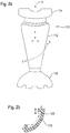
- FIG. 2a shows an overall view of the working device 110.
- This has an inner assembly 114 and an outer assembly 112.
- the inner assembly 114 can be slid with respect to the outer assembly 112, as indicated by the arrows in FIG Figure 2a is shown.
- an axial movement is automatically superimposed with a pivoting or rotary movement about the axis A.
- This corresponding movement is indicated by the arrow connecting points a and b.
- This helicoidal movement is achieved by guiding a projection 120 provided on the inner assembly 114 within a helicoidal guide 118 provided on the outer assembly, which is shown in FIG Figure 2b is shown.
- Axial movement of the inner assembly 114 with respect to the outer assembly 112 causes the projection 120 to move along the guide 118 and thus, as in FIG Figure 2b is shown, an axial movement is superimposed with a pivoting movement, which leads to a helicoidal movement of the two assemblies 112, 114 with respect to one another.
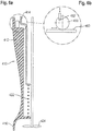
- FIG. 3a The details of the first embodiment are further in Figure 3a shown.
- the inner assembly 114 at its upper end on a motor device, which can drive the shaft 128 via the coupling 130 so that it rotates about its axis.
- a blade 124 is provided as an example of a working part.
- the shaft 128 is provided within a sleeve 134, which in turn is connected to a conical intermediate section 136 of the inner assembly.
- the shaft 128 is rotatably supported within the sleeve 134 via a bearing 135.
- the blade 124 is located within the shield 116.
- This shield 116 is part of the outer assembly 112.
- a shield 126 is provided through which the shaft 128 extends.
- a further bearing 132 is provided adjacent to the shield 126.
- an annular abutment 123 is also firmly provided, against which a spring 122 rests as an example of a restoring element.
- This spring 122 serves to bias the blade 124 in a direction towards the housing so that manual interaction is required, for example the user, who pushes the inner assembly 114 downward with respect to the outer assembly 112 in order to open the blade 124 to open the shield 116 to move.
- the outer assembly 112 also has protrusions 120 on its inner surface. These projections 120 are engaged with guide grooves 118 provided in the intermediate portion 136.
- FIG. 3b is shown a curved configuration so that they have both an axial component and a circumferential component with respect to the axis A.
- the intermediate portion 136 and the guide groove 118 are designed such that the projection 120 is guided in this guide groove 118 when an axial force is exerted on the inner subassembly 114, so that the latter is displaced with respect to the outer subassembly 112.
- the maximum stroke is here in Figures 3a and 3b denoted by d.
- This maximum stroke d is preferably a maximum of 15 mm, preferably between 5 and 15 mm.
- the inclination of the guide 118 with respect to the axial direction can be selected as needed. Typically, however, the angle with respect to the axial direction is less than 45 ° at each point of the guide 118.
- the pivoting path is a progressive path (in Figure 3c referred to as "1"), a linear path (in Figure 3c denoted as "2”) or a degressive path (denoted by "3").
- Figure 3c a denotes the starting point of the movement, i.e.
- d max denotes the maximum deflection. d denotes the respective deflection, and ⁇ max denotes the maximum angular pivoting.
- Figure 4 there is shown a second embodiment of the invention.
- Figure 4a a partial sectional view through the implement, while Figures 4b and 4c Show details of the groove guide.
- the working device 210 in turn has an inner assembly 214 and an outer assembly 212, which are biased towards one another by a spring 222.
- the outer assembly 212 has a shield 216 which in turn shields a blade 224 as an example of a working part.
- a projection 220 in the form of a sliding block is fixedly provided on the inner assembly 214.
- the outer assembly 212 there is a matching groove 218 which guides the sliding block 220.
- the sliding block is provided on the outer assembly 212 and the guide is provided on the inner assembly.
- the sliding block is provided on the outer assembly 212 and the guide is provided on the inner assembly.
- Figure 5 Figure 3 shows a third embodiment of the invention which can be understood as a "parallelogram mechanism".
- Figure 5a again a partial one Sectional view
- Figure 5b shows a detail of the guide.
- a spring 322 is again provided, which pretensions the inner assembly 314 with respect to the outer assembly 312.
- a blade 324 is also provided here within a shield 316 of the outer assembly 312.
- rods 340 are provided between the inner assembly 314 and the outer assembly 312. These rods 340 are pivotably connected to the inner assembly 314 at a first connection point 342 and to the outer assembly 312 at a second connection point 344. By exerting axial pressure on the inner assembly 314 with respect to the outer assembly 312, the rods 340 are pivoted, as shown in FIG Figure 5b is shown in dashed lines. As a result, the inner assembly 314 is pivoted with respect to the outer assembly 312. The spring 322 is used to reset it manage the tilting and the restoring force.
- FIG Figure 5b the further details of the third embodiment, reference is made to the first embodiment and Figs WO 2016/169883 A1 referenced.
- Figure 6 Figure 3 shows a fourth embodiment of the invention.
- Figure 6a a partial sectional view of this embodiment
- Figure 6b is a detailed view.
- an inner assembly 414 has a wheel 450 which is mounted eccentrically via an axle 452 (see FIG Figure 6b ). This wheel 450 rests against a contact surface 460 which is provided in the outer assembly 412 so that it runs around the circumference.
- a gear wheel can be used for the wheel 450 and a contact surface which has teeth can be used for the contact surface 460.
- a plurality of wheels or a plurality of gears are preferably used, which are preferably provided (point) symmetrically, since otherwise this configuration would be comparatively unstable and could easily jam.
- FIG. 7 there is shown a fifth embodiment of the invention.
- a thread is provided between the inner assembly 514 and the outer assembly 512.
- this may be in the form of a ball screw 570 as shown.
- a threaded insert is provided inside the outer assembly 512, while a corresponding counterpart is provided on the outside of the inner assembly 514.
- the shielding 516 and the external assembly 512 connected to it is opened by a corresponding rotational movement with respect to the inner assembly 514, which has a working part 524 mounted in the shield 516, is pivoted. In this case, too, a return is achieved via a spring 522.
Landscapes
- Engineering & Computer Science (AREA)
- Mechanical Engineering (AREA)
- Food Science & Technology (AREA)
- Food-Manufacturing Devices (AREA)
Description
Die vorliegende Erfindung betrifft ein Arbeitsgerät zum Rühren oder Zerkleinern von Nahrungsmitteln, wie zum Beispiel einen Stabmixer.The present invention relates to an implement for stirring or chopping food, such as a hand blender.
Herkömmliche Arbeitsgeräte zum Rühren oder Zerkleinern von Nahrungsmitteln sind beispielsweise aus der
Der Schaft übernimmt in der Regel die Adaption des Motorgehäuses an die Schaftbaugruppe und häufig die axiale sowie radiale Lagerung der Welle, welche zum Antrieb des Messers benötigt wird. Die Glocke hat in erster Linie eine Schutzfunktion, um das Hineingreifen in die Klinge durch den Anwender zu erschweren. Außerdem dient sie der Definition eines festen Abstands zwischen der Klinge und dem Boden des Bearbeitungsgefäßes (Topf, Rührbecher etc.), der Strömungsoptimierung um die Klinge herum sowie als Spritzschutz beim Eintauchen in Flüssigkeiten. Die Glocke ist dabei so dimensioniert, dass sie das Schneidmesser vollständig umschließt und, in Richtung der Achse der Arbeitswelle gesehen, eine bestimmte Strecke über das Ende der Welle beziehungsweise das Schneidmesser vorsteht.The shaft usually takes on the adaptation of the motor housing to the shaft assembly and often the axial one as well as radial bearing of the shaft, which is required to drive the knife. The bell primarily has a protective function in order to make it more difficult for the user to reach into the blade. It also serves to define a fixed distance between the blade and the bottom of the processing vessel (pot, mixing bowl, etc.), to optimize the flow around the blade and as a splash guard when immersed in liquids. The bell is dimensioned so that it completely encloses the cutting knife and, viewed in the direction of the axis of the working shaft, protrudes a certain distance beyond the end of the shaft or the cutting knife.
Bei diesen auf dem Markt verfügbaren Geräten sind die Klingen immer in einer definierten horizontalen Position innerhalb der Glocke angebracht. Die Klingen sind fest auf einer Welle montiert und meist radial und axial starr gelagert. Somit ergibt sich ein vom Messer erreichbarer Bearbeitungsraum, der räumlich begrenzt ist. Durch die "normale" Auf- und AbBewegung des gesamten Stabmixers durch den Bediener wird dieser Raum nur unwesentlich größer. Spätestens beim Aufsetzen der Glocke auf den Boden wird der Raum unterhalb des Messers nicht durch dieses erreicht. Die Zerkleinerung erfolgt dann in aller Regel nur noch durch Strömungseffekte. Vorausgesetzt, es befindet sich genug Flüssigkeit um das Schneidgut herum, wird dieses mit der Strömung durch den Bearbeitungsraum gezogen und somit zerkleinert.With these devices available on the market, the blades are always attached in a defined horizontal position within the bell. The blades are firmly mounted on a shaft and are usually rigidly mounted radially and axially. This results in a processing space that can be reached by the knife and that is spatially limited. The "normal" up and down movement of the entire hand blender by the operator means that this space is only marginally larger. At the latest when the bell is placed on the floor, the space below the knife is not reached by it. The comminution then usually only takes place through flow effects. Provided that there is enough liquid around the material to be cut, it will be drawn through the processing area with the flow and thus shredded.
Außerdem kann sich bei den bekannten Stabmixern der Schaft im Betrieb immer wieder am Gefäßboden festsaugen, was für den Benutzer äußerst störend sein kann, da es einen erhöhten Kraftaufwand erfordert, um den Schaft wieder vom Boden zu lösen. Dies ist hauptsächlich durch die Position des Schneidmessers innerhalb der Glocke bedingt, denn die für die Funktion sinnvolle Geometrie des Messers sorgt für einen "Propellereffekt" und bewirkt ein Ansaugen des gesamten Schafts am Bearbeitungsboden.In addition, with the known hand mixers, the shaft can repeatedly suck on the bottom of the vessel during operation, which can be extremely annoying for the user, since it requires increased effort to detach the shaft from the bottom again. This is mainly due to the position of the cutting knife within the bell, because the geometry of the knife, which is sensible for its function, ensures a "propeller effect" and causes the entire shaft to be sucked into the processing floor.
Um entsprechende Nachteile zu vermeiden, wurde in der
In der
Dem Erfinder ist aufgefallen, dass, wenn zum Beispiel vergleichsweise harte Nahrungsmittel bearbeitet werden (zum Beispiel rohe Karotten), sich Nahrungsmittelstückchen direkt unterhalb die Wände der Glocke oder zwischen die Glocke und den Boden des Bearbeitungsbehälters bewegen und dort festsetzen können. In einer solchen Situation kann die Klinge die Nahrung nicht mehr erreichen, wodurch diese die Nahrungsmittel nicht mehr weiter verarbeiten kann. Bei Versuchen wurde ferner festgestellt, dass, um sicher zu stellen, dass solche Nahrungsmittelrückstände erreicht werden können, eine Kraft von bis zu 160 Newton ausgeübt werden muss, um die Wand der Glocke tief genug in die Nahrung hineinzudrücken, sodass das Messer die Nahrung erreichen kann. Für viele Benutzer ist dies nicht möglich.The inventor has noticed that when, for example, comparatively hard foods are processed (for example raw carrots), pieces of food can move directly below the walls of the bell or between the bell and the bottom of the processing container and can get stuck there. In such a situation, the blade can no longer reach the food, which means that it can no longer process the food. Tests have also found that to ensure that such food residue can be reached, a force of up to 160 Newtons must be applied to push the wall of the bell deep enough into the food for the knife to reach the food . For many users this is not possible.
Demgemäß wurde festgestellt, dass die Benutzer dazu tendieren, das Arbeitsgerät aus der Nahrung herauszuziehen und an anderer Stelle wieder einzutauchen. Andere, erfahrenere Benutzer, tendieren dazu, das gesamte Arbeitsgerät beziehungsweise den gesamten Mixer zu verschwenken oder um die Hochachse zu drehen, während sie das Arbeitsgerät herabdrücken, um dafür zu sorgen, dass die harten Nahrungsmittelstücke sich von ihrem Ort unterhalb der Wände der Glocke weg bewegen. Dies führt jedoch dazu, dass der Benutzer den gesamten Arm verschwenken muss, während er gleichzeitig einen (signifikanten) vertikalen Druck ausüben muss. Für den Benutzer ist dies umständlich, und es hat sich außerdem herausgestellt, dass die entsprechenden Ergebnisse der derartig bearbeiteten Nahrung deutlich verschlechtert sind.Accordingly, it has been found that users tend to pull the implement out of the food and re-immerse it in another location. Other, more experienced users tend to pivot or rotate the entire implement or the entire mixer about the vertical axis while depressing the implement in order to cause the hard pieces of food to move away from their location below the walls of the bell . However, this results in the user has to pivot the entire arm while applying a (significant) vertical pressure at the same time. This is inconvenient for the user, and it has also been found that the corresponding results of the food processed in this way are significantly impaired.
Dem Erfinder ist ferner aufgefallen, dass das in der
Demgemäß hat die Erfindung die Aufgabe, zumindest einige der oben genannten Probleme zu lindern.Accordingly, it is an object of the invention to alleviate at least some of the problems noted above.
Die Erfindung wird durch Anspruch 1 definiert. Bevorzugte Ausführungsformen werden in den abhängigen Ansprüchen beschrieben.The invention is defined by
Erfindungsgemäß weist ein Arbeitsgerät zum Rühren oder Zerkleinern von Nahrungsmitteln eine von einem Motor angetriebene drehbare Welle auf, an deren dem Motor gegenüberliegenden Ende ein Arbeitsteil vorgesehen ist. Bei einem solchen Arbeitsgerät kann es sich um einen Stabmixer oder ein Handrührgerät handeln. Der Motor ist typischerweise ein Elektromotor, es kann sich jedoch um eine beliebige andere Art von Motor handeln. Bei dem an dem Motor vorgesehenen Arbeitsteil kann es sich zum Beispiel um eine Klinge, ein Messer, ein Rührwerkzeug oder ein Knetwerkzeug (wie z.B. einen Rührstab) handeln. Allgemein gesagt kann es sich hierbei um eine beliebige Art von Arbeitsteil handeln, welches man bei der Verarbeitung von Nahrungsmitteln verwenden kann und welches hierfür drehend bzw. rotatorisch oszillierend eingesetzt wird.According to the invention, a working device for stirring or chopping food has a rotatable shaft driven by a motor, at the end of which a working part is provided opposite the motor. Such a tool can be a hand blender or a hand mixer. The motor is typically an electric motor, but it can be any other type of motor. The working part provided on the motor can be, for example, a blade, a knife, a stirring tool or a kneading tool (such as a stirring rod). Generally speaking, this can be any type of work part, which can be used in the processing of foodstuffs and which is used for this purpose in a rotating or rotating oscillating manner.
Das Arbeitsgerät weist eine innere und eine äußere Baugruppe auf, die zumindest teilweise ein Gehäuse ("Schaft") des Arbeitsgeräts definieren. Bei dieser inneren und äußeren Baugruppe handelt es sich um Komponenten des Gehäuses. Typischerweise definieren diese eine längliche Außenform des Arbeitsgeräts. Die innere Baugruppe ist innerhalb der äußeren Baugruppe beweglich vorgesehen und kann bezüglich der äußeren Baugruppe verschoben werden, wie dies auch in der
Das Arbeitsteil ist jedoch innerhalb einer Abschirmung vorgesehen, die an der äußeren Baugruppe vorgesehen ist. Bei dieser Abschirmung (die auch als "Glocke" bezeichnet wird) handelt es sich um eine Vorrichtung, die dazu dient, ein unbeabsichtigtes Hereingreifen in das sich drehende Arbeitsteil zu vermeiden. Auch eine solche Glocke ist beispielsweise in der
Die innere Baugruppe ist bezüglich der äußeren Baugruppe axial in Richtung der Welle bewegbar. Bei einer solchen Bewegung wird die innere Baugruppe, zusammen mit der von ihr gelagerten Welle, bezüglich der äußeren Baugruppe axial verschoben. Die innere Baugruppe ist bezüglich der äußeren Baugruppe so gelagert, dass eine axiale Bewegung der inneren Baugruppe in Bezug auf die äußere Baugruppe zusätzlich zu einer Drehbewegung der äußeren Baugruppe bezüglich der inneren Baugruppe führt. Durch eine entsprechende Lagerung der inneren Baugruppe bezüglich der äußeren Baugruppe kann durch eine Axialbewegung der inneren Baugruppe bezüglich der äußeren Baugruppe eine Verschwenkung der inneren Baugruppe bezüglich der äußeren Baugruppe erzielt werden. Dies führt dann dazu, dass sich auch die Abschirmung bezüglich des Arbeitsteils und gegenüber des an der inneren Baugruppe befestigen Motors bzw. Griffteils verschwenkt.The inner assembly is axially movable in the direction of the shaft with respect to the outer assembly. With such a movement, the internal assembly, along with that of it mounted shaft, axially displaced with respect to the outer assembly. The inner assembly is mounted with respect to the outer assembly such that an axial movement of the inner assembly with respect to the outer assembly additionally results in a rotational movement of the outer assembly with respect to the inner assembly. By correspondingly mounting the inner assembly with respect to the outer assembly, an axial movement of the inner assembly with respect to the outer assembly allows the inner assembly to pivot with respect to the outer assembly. This then leads to the shielding also pivoting with respect to the working part and with respect to the motor or handle part attached to the inner assembly.
Im Vergleich zu der
Durch die Erfindung wird diese Drehbewegung automatisch durchgeführt, ohne dass der Benutzer irgendetwas "besonderes" durchführen muss. Diese Drehbewegung wird direkt durch die Axialbewegung erzeugt, welches die normale und intuitive Bewegungsrichtung für ein entsprechendes Arbeitsgerät wie zum Beispiel einen Stabmixer ist. Demgemäß werden die notwendigen Kräfte reduziert und es können auch unerfahrene Benutzer bessere Ergebnisse beim Rühren und Zerkleinern speziell von harten Nahrungsmitteln erzielen.This rotary movement is carried out automatically by the invention, without the user having to do anything "special". This rotary movement is generated directly by the axial movement, which is the normal and intuitive direction of movement for a corresponding tool such as a hand blender. Accordingly, the necessary forces are reduced and even inexperienced users can do it get better results when stirring and chopping especially hard foods.
Bevorzugt wird, wenn das Arbeitsgerät ferner ein Vorspannelement (zum Beispiel in Form einer Feder) aufweist, welches gegen eine Verschiebung der inneren Baugruppe bezüglich der äußeren Baugruppe in axialer Richtung wirkt. Eine entsprechende Vorspanneinrichtung führt dazu, dass das Arbeitsgerät eine definierte Ruheposition hat, die es einnimmt, wenn keine axiale Kraft auf die innere und äußere Baugruppe ausgeübt wird. Ein entsprechendes Arbeitsgerät ist somit benutzerfreundlich und wenig wartungsintensiv, da die innere und äußere Baugruppe im Ruhezustand wenig Spiel aufweisen. Ferner wird keine separate Betätigung für das Rückstellen benötigt, da die Feder selbst als Rückstellelement dient. Besondere ist von Vorteil, wenn dieses Vorspannelement so wirkt, dass im Ruhezustand das Arbeitsteil den maximalen Abstand von der Öffnung der Glocke hat. Hierdurch wird die Wahrscheinlichkeit verringert, dass ein Benutzer versehentlich mit dem Arbeitsteil in Kontakt kommt, und das Ansaugen an den Behälterboden wird minimiert.It is preferred if the working device also has a prestressing element (for example in the form of a spring) which acts against a displacement of the inner assembly with respect to the outer assembly in the axial direction. A corresponding pretensioning device means that the working device has a defined rest position which it assumes when no axial force is exerted on the inner and outer assembly. A corresponding work device is therefore user-friendly and requires little maintenance, since the inner and outer assemblies have little play in the idle state. Furthermore, no separate actuation is required for resetting, since the spring itself serves as a resetting element. It is particularly advantageous if this prestressing element acts in such a way that the working part is at the maximum distance from the opening of the bell when it is at rest. This reduces the likelihood that a user will accidentally come into contact with the working part, and the suction to the container bottom is minimized.
Bevorzugt wird ferner, wenn der maximale axiale "Hub" der inneren Baugruppe bezüglich der äußeren Baugruppe, und damit der maximale axiale Hub des Arbeitsgeräts, maximal 15 mm beträgt.It is also preferred if the maximum axial "stroke" of the inner assembly with respect to the outer assembly, and thus the maximum axial stroke of the working device, is a maximum of 15 mm.
Bevorzugt wird, dass die Lagerung der inneren Baugruppe bezüglich der äußeren Baugruppe einen oder mehrere Vorsprünge an einer unter der inneren Baugruppe und der äußeren Baugruppe und eine oder mehrere entsprechende Führungen an der jeweils anderen unter der inneren Baugruppe und der äußeren Baugruppe aufweist, welche die eine oder mehreren Vorsprünge jeweils führen. Das heißt, der eine oder die mehreren Vorsprünge sind mit der zugehörigen Führung in Eingriff. Eine entsprechende Führung könnte zum Beispiel durch Vertiefungen in einer der jeweiligen Baugruppen ausgebildet sein. Es wäre jedoch auch denkbar, dass Führungsschienen vorgesehen sind, die sich von der jeweiligen Oberfläche der Baugruppe erstrecken.It is preferred that the mounting of the inner assembly with respect to the outer assembly has one or more projections on one under the inner assembly and the outer assembly and one or more corresponding guides on the other under the inner assembly and the outer assembly, which one or more projections each lead. That is, the one or more protrusions are engaged with the associated guide. A corresponding guide could, for example, be provided by indentations in one of the respective assemblies be trained. However, it would also be conceivable that guide rails are provided which extend from the respective surface of the assembly.
Die einen oder mehreren Führungen erstrecken sich entlang der jeweiligen Baugruppe so, dass sie entlang ihrer Erstreckungsrichtung sowohl eine axiale Erstreckung als auch eine Erstreckung entlang des Umfangs haben. Dies führt dazu, dass eine Bewegung der einen oder mehreren Vorsprünge entlang der Führung(en) zu der Drehbewegung der äußeren Baugruppe bezüglich der inneren Baugruppe führt. Eine entsprechende Ausgestaltung des Arbeitsgeräts kann leicht implementiert werden und führt zu einem robusten und langlebigen Arbeitsgerät.The one or more guides extend along the respective assembly in such a way that they have both an axial extent and an extent along the circumference along their direction of extent. As a result, movement of the one or more projections along the guide (s) results in the rotational movement of the outer assembly with respect to the inner assembly. A corresponding design of the working device can be easily implemented and leads to a robust and long-lasting working device.
Diesbezüglich wird bevorzugt, dass die Führung eine Folge von sich abwechselnden axial ausgerichteten Abschnitten und geneigten Abschnitten aufweist. Ein entsprechendes Führungsprinzip ist zum Beispiel aus einem handelsüblichen Kugelschreiber bekannt. Dies führt dazu, dass eine erste axiale Verschiebung der inneren Baugruppe bezüglich der äußeren Baugruppe zu einer Verschwenkung des Arbeitsteils mit gleichzeitiger axialer Bewegung des Arbeitsteils führt, während ein Loslassen dazu führt, dass das Arbeitsteil lediglich axial zurückgeführt wird. Ein entsprechend ausgebildetes Arbeitsteil ist leicht einsetzbar und hat sich in der Praxis als praktisch und einfach handhabbar erwiesen.In this regard, it is preferred that the guide has a sequence of alternating axially aligned sections and inclined sections. A corresponding guiding principle is known, for example, from a commercially available ballpoint pen. This leads to the fact that a first axial displacement of the inner assembly with respect to the outer assembly leads to a pivoting of the working part with simultaneous axial movement of the working part, while a release results in the working part only being returned axially. A correspondingly designed working part is easy to use and has proven to be practical and easy to use in practice.
Weiterhin wird bevorzugt, dass die Lagerung der inneren Baugruppe bezüglich der äußeren Baugruppe eines oder mehrere Verbindungselemente aufweist. Diese Verbindungselemente weisen jeweils einen ersten Verbindungspunkt mit der inneren Baugruppe und einen zweiten Verbindungspunkt mit der äußeren Baugruppe auf, an denen sie jeweils mit der inneren beziehungsweise der äußeren Baugruppe angebracht sind. Der erste Verbindungspunkt und der zweite Verbindungspunkt sind voneinander beabstandet. Das eine oder die mehreren Verbindungselemente haben eine hinreichende Steifigkeit und sind so ausgebildet, dass das Ausüben eines axialen Druck auf die innere Baugruppe zu einer Schwenkbewegung des einen oder der mehreren Verbindungselement führt, welche zu einer Drehbewegung der äußeren Baugruppe bezüglich der inneren Baugruppe führt. Entsprechende Verbindungselemente lassen sich leicht implementieren und haben sich auch als wenig wartungsintensiv und robust herausgestellt.It is also preferred that the mounting of the inner assembly has one or more connecting elements with respect to the outer assembly. These connecting elements each have a first connection point with the inner assembly and a second connection point with the outer assembly, at which they are attached to the inner and the outer assembly, respectively. The first connection point and the second connection point are spaced from each other. One or more Connecting elements have sufficient rigidity and are designed such that the exertion of an axial pressure on the inner assembly leads to a pivoting movement of the one or more connecting elements, which leads to a rotational movement of the outer assembly with respect to the inner assembly. Corresponding connecting elements can be easily implemented and have also proven to be less maintenance-intensive and robust.
Es wird bevorzugt, dass die Verbindungselemente Stäbe aufweisen, die an der inneren und der äußeren Baugruppe befestigt sind, wobei sie verschwenkbar gelagert sind. Eine entsprechende Ausgestaltung ist einfach implementierbar.It is preferred that the connecting elements have rods which are attached to the inner and outer assemblies, wherein they are pivotably mounted. A corresponding configuration is easy to implement.
Weiterhin wird bevorzugt, dass die Verbindungselemente Blattfedern aufweisen, die an der inneren Baugruppe und der äußeren Baugruppe befestigt sind. Diese Blattfedern weisen als Vorteil auf, dass kein separates Rückstellelement nötig ist oder ein solches schwächer ausgebildet werden kann, da die Blattfedern diese Rückstellfunktion zumindest in Teilen übernehmen.It is further preferred that the connecting elements have leaf springs which are fastened to the inner assembly and the outer assembly. These leaf springs have the advantage that no separate return element is necessary or that such a return element can be made weaker, since the leaf springs take over this return function at least in part.
Eine weitere bevorzugte Ausführungsform ist, dass an einer unter der inneren Baugruppe und der äußeren Baugruppe eines oder mehrere exzentrisch gelagerte Räder vorgesehen sind, die gegen eine Anlageoberfläche in Anlage kommen können oder gegen diese in der Anlage sind, die an der jeweils anderen unter der inneren Baugruppe und der äußeren Baugruppe vorgesehen ist und die sich so erstreckt, dass ihre Erstreckung eine Komponente hat, die entlang der Umfangsrichtung ist. Hierbei sind die Räder und die Anlageoberfläche so ausgebildet, dass beim axialen Verschieben der inneren Baugruppe bezüglich der äußeren Baugruppe diese Räder auf die Anlageoberfläche gedrückt werden und auf dieser aufgrund der exzentrischen Lagerung rollen. Durch dieses Rollen üben die Räder eine entlang der Umfangsrichtung gerichtete Kraft auf die Anlageoberfläche aus, die zu der Drehbewegung der äußeren Baugruppe bezüglich der inneren Baugruppe führt. Eine entsprechende Ausgestaltung des Arbeitsgeräts ist vergleichsweise robust, was unbeabsichtigte Verdrehungen der inneren Baugruppe bezüglich der äußeren Baugruppe angeht, weshalb es weniger wahrscheinlich ist, dass ein solches Arbeitsgerät aufgrund unsachgemäßer Benutzung beschädigt wird.Another preferred embodiment is that one or more eccentrically mounted wheels are provided on one of the inner subassembly and the outer subassembly, which can come into contact with a contact surface or are in contact with this, which on the other under the inner Assembly and the outer assembly is provided and which extends so that its extension has a component that is along the circumferential direction. Here, the wheels and the contact surface are designed so that when the inner assembly is axially displaced with respect to the outer assembly, these wheels are pressed onto the contact surface and roll on it due to the eccentric mounting. As a result of this rolling, the wheels exert a force directed along the circumferential direction on the contact surface which results in the rotational movement of the outer assembly with respect to the inner assembly. A corresponding embodiment of the work device is comparatively robust with regard to unintentional twisting of the inner assembly with respect to the outer assembly, which is why it is less likely that such a work device will be damaged due to improper use.
Hierbei wird bevorzugt, dass die Räder Zahnräder sind und dass die Anlageoberfläche Zahnelemente aufweist, die mit den Zähnen der Zahnräder in Eingriff sind oder in Eingriff treten können. Bei einer entsprechenden Kraftübertragung können sehr gut vergleichsweise große Kräfte übertragen werden.It is preferred here that the wheels are toothed wheels and that the contact surface has toothed elements which mesh or can mesh with the teeth of the toothed wheels. With a corresponding power transmission, comparatively large forces can be transmitted very well.
Alternativ hierzu reicht es aus, wenn die Räder und die Anlageoberfläche eine Reibradverbindung haben oder eingehen können. Dies ist dahingehend von Vorteil, dass eine solche Ausbildung der Räder und der Anlageoberfläche in einer beliebigen Ausrichtung der Räder und der Anlageoberfläche zu einer Kraftübertragung führen kann, was sich gegenüber der Ausführungsform unterscheidet, bei der die Räder Zahnräder und die Anlageoberfläche Zahnelemente aufweist. Insofern ist ein solches Arbeitsgerät benutzerfreundlicher.Alternatively, it is sufficient if the wheels and the contact surface have or can enter into a friction wheel connection. This is advantageous in that such a design of the wheels and the contact surface can lead to a power transmission in any orientation of the wheels and the contact surface, which differs from the embodiment in which the wheels have gears and the contact surface has toothed elements. In this respect, such a work device is more user-friendly.
Es wird weiterhin bevorzugt, dass die innere Baugruppe und die äußere Baugruppe mittels eines Gewindes miteinander verbunden sind, welches derart ausgebildet ist, dass es bei einer axialen Bewegung der inneren Baugruppe bezüglich der äußeren Baugruppe zu einer Drehbewegung der äußeren Baugruppe bezüglich der inneren Baugruppe führt. Eine entsprechende Ausstattung des Arbeitsgeräts kann leicht implementiert werden und ist robust, da ein solches Arbeitsgerät nur wenig Spiel hat. Hierbei wird bevorzugt, dass das Gewinde ein Kugelgewinde, ein Rollgewinde oder ein Gleitgewinde ist oder ein solches aufweist. Entsprechende Gewinde sind gut charakterisiert und insofern gut implementierbar. Ein Kugelgewinde ist besonders leichtgängig und wird daher besonders bevorzugt.It is further preferred that the inner subassembly and the outer subassembly are connected to one another by means of a thread which is designed such that when the inner subassembly moves axially with respect to the outer subassembly, it leads to a rotary movement of the outer subassembly with respect to the inner subassembly. Appropriate equipment for the work device can easily be implemented and is robust, since such a work device has little play. It is preferred here that the thread is or has a ball thread, a rolling thread or a sliding thread. Corresponding threads are well characterized and therefore easy to implement. A Ball screw is particularly smooth and is therefore particularly preferred.
- Figuren 1a und 1bFigures 1a and 1b
- zeigen ein Arbeitsgerät nach dem Stand der Technik.show an implement according to the prior art.
- Figuren 2a und 2bFigures 2a and 2b
- zeigen die Funktionsweise eines erfindungsgemäßen Arbeitsgeräts gemäß der ersten Ausführungsform.show the mode of operation of a working device according to the invention according to the first embodiment.
- Figuren 3a bis 3cFigures 3a to 3c
- illustrieren das Arbeitsgerät gemäß der ersten Ausführungsform.illustrate the working device according to the first embodiment.
- Figur 4Figure 4
- zeigt ein Arbeitsgerät gemäß einer zweiten Ausführungsform.shows an implement according to a second embodiment.
- Figur 5Figure 5
- zeigt ein Arbeitsgerät gemäß einer dritten Ausführungsform.shows a working device according to a third embodiment.
- Figur 6Figure 6
- zeigt ein Arbeitsgerät gemäß einer vierten Ausführungsform.shows an implement according to a fourth embodiment.
- Figur 7Figure 7
- zeigt ein Arbeitsgerät gemäß einer fünften Ausführungsform.shows an implement according to a fifth embodiment.
Eine Axialbewegung - durch einen Pfeil angedeutet - der inneren Baugruppe 14 bezüglich der äußeren Baugruppe 12 führt dazu, dass sich eine innerhalb der Abschirmung 16 vorgesehenen Klinge (nicht dargestellt) des Arbeitsgeräts 10 axial verschiebt. Dies wird dadurch erzielt, dass zum Beispiel an der inneren Baugruppe 14 eine Führung 18 vorgesehen ist, innerhalb der ein Vorsprung 20 geführt wird, der an der äußeren Baugruppe 12 vorgesehen ist. Diese Führung 18 ist, wie in
Eine erste Ausführungsform der Erfindung wird nun unter Bezugnahme auf
Diese helikoidale Bewegung wird durch die Führung eines an der inneren Baugruppe 114 vorgesehenen Vorsprungs 120 innerhalb einer an der äußeren Baugruppe vorgesehenen helikoidalen Führung 118 erzielt, die in
Die Details der ersten Ausführungsform werden weiter in
Wie bereits erwähnt befindet sich die Klinge 124 innerhalb der Abschirmung 116. Diese Abschirmung 116 ist ein Teil der äußeren Baugruppe 112. Um die Klinge 124 gegenüber dem Innenraum des Arbeitsgeräts 110 abzuschirmen, ist eine Abschirmung 126 vorgesehen, durch welche sich die Welle 128 erstreckt. Benachbart zu der Abschirmung 126 ist eine weitere Lagerung 132 vorgesehen. An der Innenseite der Hülse 134 ist ferner eine ringförmige Anlage 123 fest vorgesehen, gegen die eine Feder 122 als ein Beispiel eines Rückstellelements anliegt. Diese Feder 122 dient dazu, die Klinge 124 zu einer Richtung zum Gehäuse hin vorzuspannen, sodass es einer manuellen Interaktion zum Beispiel des Benutzers bedarf, der die innere Baugruppe 114 bezüglich der äußeren Baugruppe 112 nach unten drückt, um die Klinge 124 zur Öffnung der Abschirmung 116 hin zu bewegen.As already mentioned, the
Wie in
Diese Führungsnuten haben, wie in
Durch diese Verschiebung, die in axialer Richtung geschieht, wird der Vorsprung 120 innerhalb der Nut 118 bewegt, was zu einer Verschwenkung der inneren Baugruppe 114 bezüglich der äußeren Baugruppe führt.As a result of this displacement, which occurs in the axial direction, the
Der maximale Hub wird hierbei in
In
Gemäß
An der inneren Baugruppe 214 ist ein Vorsprung 220 in Form eines Nutsteins fest vorgesehen. In der äußeren Baugruppe 212 befindet sich eine hierzu passende Nut 218, die den Nutstein 220 führt.A
Wie in
Des Weiteren ist es, wie in
Des Weiteren ist es auch möglich, dass der Nutstein an der äußeren Baugruppe 212 vorgesehen ist und die Führung an der inneren Baugruppe vorgesehen ist. Für Details dieses "Kugelschreibermechanismus" und die weiteren Details der zweiten Ausführungsform wird auf die erste Ausführungsform und auf die
Wie insbesondere in
Durch das Ausüben einer axialen Kraft auf die innere Baugruppe 414 wird wiederum eine Kraft auf die Achse 452 ausgeübt. Durch den Eingriff beziehungsweise den Kontakt des Rades 450 mit der Anlageoberfläche 460 führt dies zu einer Verdrehung des Rades um dessen geometrische Mitte, die wiederum zu einem Drehmoment führt, welches auf die äußere Baugruppe 412 über die Anlageoberfläche 460 ausgeübt wird. Dies führt wiederum zu einem Verschwenken der äußeren Baugruppe 412 und der damit verbundenen Abschirmung 416 bezüglich der innerhalb der inneren Baugruppe 414. Auch hierbei wird eine Rückstellung des Arbeitsgeräts 410 über die Feder 422 erzielt.By exerting an axial force on the
Insbesondere kann hierbei für das Rad 450 ein Zahnrad und für die Anlageoberfläche 460 eine Anlageoberfläche verwendet werden, welche Zähne aufweist.In particular, a gear wheel can be used for the
Bevorzugt werden mehrere Räder beziehungsweise mehrere Zahnräder verwendet, die vorzugsweise (punkt)symmetrisch vorgesehen sind, da ansonsten diese Ausgestaltung vergleichsweise instabil wäre und leicht verklemmen könnte.A plurality of wheels or a plurality of gears are preferably used, which are preferably provided (point) symmetrically, since otherwise this configuration would be comparatively unstable and could easily jam.
Was die weiteren Details der vierten Ausführungsform angeht, wird auf die erste Ausführungsform und die
In
Claims (10)
- Implement (110) for stirring or comminuting food having:a rotatable shaft (128) driven by a motor, with a working part (124) provided at the end opposite the motor,an inner assembly (114) and an outer assembly (112) which at least partially define a housing of the implement, wherein the inner assembly (114) is moveable within the outer assembly (112)and wherein the shaft (128) is mounted rotatably on the inner assembly (114) in such a way that the working part (124) is located on an outer side of the implement, enabling it to stir or comminute food,wherein the working part (124) is provided within a shield (116) which is provided on the outer assembly,wherein the inner assembly (114) together with the shaft (128) mounted thereon is axially moveable relative to the external assembly (112) in the direction of the shaft (128), characterised in that the inner assembly (114) is mounted in such a way relative to the outer assembly (112) that an axial movement of the inner assembly (114) relative to the outer assembly (112) leads to a rotational movement of the outer assembly (114) relative to the inner assembly (112) .
- Implement according to claim 1,
wherein the mounting of the inner assembly relative to the outer assembly comprises one or more projections (120) on either the inner assembly or the outer assembly and one or more corresponding guides (118) on the other assembly which in each case guide the one or more projections (120),
wherein the one or more guides (118) extend along the respective assembly in such a way that they extend both axially and also circumferentially along their direction of extension, so that a movement of the one or more projections (120) along said guides leads to the rotational movement of the outer assembly (112) relative to the inner assembly (114). - Implement according to claim 2, wherein the guide has a sequence of alternating axially oriented sections (218a) and inclined sections (218b).
- Implement according to one of the preceding claims,
wherein the mounting of the inner assembly relative to the outer assembly comprises one or more connecting elements (340),
wherein the connecting elements (340) in each case have a first connection point (342) with the inner assembly and a second connection point (344) with the outer assembly at which they are each connected, respectively, to the inner or outer assembly,
wherein the first connection point (342) and the second connection point (344) are spaced apart from each other and wherein the one or more connecting elements are so stiff and are configured such that the exertion of an axial pressure on the inner assembly leads to a swivelling movement of the one or more connecting elements (340) which leads to a rotational movement of the outer assembly (312) relative to the inner assembly (314). - Implement according to claim 4, wherein the connecting elements comprise rods which are fastened to the inner assembly and the outer assembly, wherein the rods are mounted so as to swivel.
- Implement according to claim 4 or 5, wherein the connecting elements comprise leaf springs which are fastened to the inner assembly and the outer assembly.
- Implement according to one of the preceding claims,
wherein eccentrically mounted wheels (450) are provided on either the inner assembly or the external assembly which can come into contact with a contact surface (460) provided on the other assembly, or are in contact with said contact surface, and extend in such a way that their extension has a component which extends in a circumferential direction,
wherein in the event of an axial movement of the inner assembly relative to the outer assembly the wheels (450) roll on the contact surface (460) so that they exert a force directed along the circumferential direction which leads to the rotational movement of the external assembly relative to the inner assembly. - Implement according to claim 7,
wherein the wheels are gearwheels and the contact surface has tooth elements which engage with, or can come into engagement with, the teeth of the gearwheel. - Implement according to claim 7,
wherein the wheels and the contact surface have, or can enter into, a friction wheel connection. - Implement according to one of the preceding claims,
wherein the inner assembly and the outer assembly are connected with each other by means of a thread (570) which is configured in such a way that in the event of an axial movement of the inner assembly relative to the outer assembly it leads to a rotational movement of the outer assembly relative to the inner assembly,
wherein the thread is preferably a ball thread, a roller thread or a sliding thread.
Applications Claiming Priority (2)
| Application Number | Priority Date | Filing Date | Title |
|---|---|---|---|
| DE102017213778.9A DE102017213778B4 (en) | 2017-08-08 | 2017-08-08 | Implement for stirring or chopping foodstuffs |
| PCT/EP2018/068631 WO2019029928A1 (en) | 2017-08-08 | 2018-07-10 | Implement for stirring or comminuting food |
Publications (2)
| Publication Number | Publication Date |
|---|---|
| EP3664671A1 EP3664671A1 (en) | 2020-06-17 |
| EP3664671B1 true EP3664671B1 (en) | 2021-08-25 |
Family
ID=62981180
Family Applications (1)
| Application Number | Title | Priority Date | Filing Date |
|---|---|---|---|
| EP18743428.7A Active EP3664671B1 (en) | 2017-08-08 | 2018-07-10 | Implement for stirring or comminuting food |
Country Status (7)
| Country | Link |
|---|---|
| US (1) | US11432682B2 (en) |
| EP (1) | EP3664671B1 (en) |
| JP (1) | JP6963674B2 (en) |
| CN (1) | CN111246785B (en) |
| DE (1) | DE102017213778B4 (en) |
| RU (1) | RU2731610C1 (en) |
| WO (1) | WO2019029928A1 (en) |
Families Citing this family (2)
| Publication number | Priority date | Publication date | Assignee | Title |
|---|---|---|---|---|
| DE102018207506B4 (en) | 2018-05-15 | 2020-10-15 | De'longhi Braun Household Gmbh | Household appliance for processing food with a splash guard |
| DE102019206029B4 (en) | 2019-04-26 | 2022-02-10 | De'longhi Braun Household Gmbh | Kitchen utensil and accessory for sealing a protective hood of a kitchen utensil |
Family Cites Families (28)
| Publication number | Priority date | Publication date | Assignee | Title |
|---|---|---|---|---|
| US4480926A (en) * | 1983-05-13 | 1984-11-06 | Lattery Jr William F | Powdered food product mixing device |
| JPS6158575A (en) * | 1984-08-29 | 1986-03-25 | Nippon Light Metal Co Ltd | Method and apparatus for preparation of home liquor, etc. |
| US4708487A (en) * | 1987-10-17 | 1987-11-24 | Robert Marshall | Space saver blender |
| IT220145Z2 (en) | 1990-09-07 | 1993-06-23 | Eleday Export | MULTIFUNCTIONAL TABLE DEVICE, MOTORIZED BY AN IMMERSION BLENDER |
| DE4436092C1 (en) | 1994-10-10 | 1995-11-30 | Braun Ag | Food processing and mixing unit, protected against food ingress, |
| DE19503491A1 (en) | 1995-02-03 | 1996-08-08 | Braun Ag | Rotating cutting knife for an electrically operated mixer in household appliances |
| DE19504638A1 (en) | 1995-02-13 | 1996-08-14 | Braun Ag | Process for a working device, in particular a hand blender, for stirring or chopping food in a container |
| FR2743710B1 (en) | 1996-01-24 | 1998-02-27 | Seb Sa | MULTI-PURPOSE ROBOT HOUSEHOLD APPLIANCES FOR CULINARY PREPARATION, INCLUDING A SUPPORT FOR THE ROTARY WORK UNIT |
| US5863118A (en) | 1997-07-29 | 1999-01-26 | Conair Corporation | Blender with extendible housing |
| DE19750813C2 (en) * | 1997-11-17 | 2002-06-13 | Braun Gmbh | Tool for stirring or chopping food, especially hand blenders |
| DE19812541A1 (en) | 1998-03-21 | 1999-09-30 | Braun Gmbh | Bell-shaped shield for use in a household appliance, in particular a hand mixer or hand mixer |
| JP5139272B2 (en) * | 2005-06-10 | 2013-02-06 | コーニンクレッカ フィリップス エレクトロニクス エヌ ヴィ | Blender arm and food processor |
| US9107540B2 (en) | 2007-10-05 | 2015-08-18 | Main Power Electrical Factory Ltd. | Handheld electric mixer |
| FR2932669B1 (en) * | 2008-06-20 | 2010-08-13 | Seb Sa | APPARATUS FOR THE PREPARATION OF FOAM FROM A LIQUID |
| US8596192B2 (en) | 2010-02-05 | 2013-12-03 | Progressive International Corporation | Vegetable cutter |
| CN101856200B (en) * | 2010-03-10 | 2012-12-12 | 广东新宝电器股份有限公司 | Cutter braking structure of food processor |
| ES2373176B1 (en) | 2010-06-10 | 2012-12-10 | Electrodomésticos Taurus, S.L. | HANDBAND WITH SEPARABLE HEAD. |
| CN202341837U (en) * | 2011-12-19 | 2012-07-25 | 广东新宝电器股份有限公司 | Stirring rod structure |
| US9149156B2 (en) * | 2012-04-09 | 2015-10-06 | Sharkninja Operating Llc | Food processor |
| CN102645381B (en) * | 2012-04-19 | 2014-07-02 | 山西潞安环保能源开发股份有限公司 | Hydraulic rotary power device |
| CN103372388B (en) * | 2012-04-23 | 2017-02-08 | 主力智业(深圳)电器实业有限公司 | Handheld electric mixer |
| CH706773B1 (en) * | 2012-07-24 | 2016-08-31 | Swizzzprozzz Vertriebs Ag | Effective use for a device for processing foodstuffs. |
| JP6486029B2 (en) | 2014-07-28 | 2019-03-20 | 株式会社カジワラ | Heating and stirring device |
| DE102015207197B3 (en) | 2015-04-21 | 2016-06-16 | De'longhi Braun Household Gmbh | Stabmixer knife with milling edge |
| DE102015207196B3 (en) | 2015-04-21 | 2016-05-25 | De'longhi Braun Household Gmbh | Tool with telescopically movable shaft for stirring or chopping food |
| DE102015216678B4 (en) | 2015-09-01 | 2023-11-09 | De'longhi Braun Household Gmbh | Hand-held electrically powered household appliance with mode selection |
| CN205885333U (en) * | 2016-05-31 | 2017-01-18 | 温州冲亚电子科技有限公司 | Electric egg beater |
| CN205664615U (en) * | 2016-06-08 | 2016-10-26 | 佛山市顺德区美的电热电器制造有限公司 | Material drying device and cooking machine |
-
2017
- 2017-08-08 DE DE102017213778.9A patent/DE102017213778B4/en not_active Expired - Fee Related
-
2018
- 2018-07-10 CN CN201880060492.XA patent/CN111246785B/en active Active
- 2018-07-10 JP JP2020506902A patent/JP6963674B2/en active Active
- 2018-07-10 EP EP18743428.7A patent/EP3664671B1/en active Active
- 2018-07-10 US US16/637,149 patent/US11432682B2/en active Active
- 2018-07-10 WO PCT/EP2018/068631 patent/WO2019029928A1/en unknown
- 2018-07-10 RU RU2020109663A patent/RU2731610C1/en active
Also Published As
| Publication number | Publication date |
|---|---|
| US20200359840A1 (en) | 2020-11-19 |
| JP6963674B2 (en) | 2021-11-10 |
| WO2019029928A1 (en) | 2019-02-14 |
| DE102017213778B4 (en) | 2019-10-10 |
| EP3664671A1 (en) | 2020-06-17 |
| CN111246785B (en) | 2022-05-17 |
| DE102017213778A1 (en) | 2019-02-14 |
| CN111246785A (en) | 2020-06-05 |
| US11432682B2 (en) | 2022-09-06 |
| RU2731610C1 (en) | 2020-09-07 |
| JP2020529281A (en) | 2020-10-08 |
Similar Documents
| Publication | Publication Date | Title |
|---|---|---|
| EP3285626B1 (en) | Hand blender blade with milling edge | |
| EP3285628B1 (en) | Implement with telescopically movable funnel for stirring or chopping foodstuffs | |
| EP0529287B1 (en) | Comminuting device for an electrical kitchen appliance | |
| EP1137518B1 (en) | Device for dicing garlic | |
| DE19750813C2 (en) | Tool for stirring or chopping food, especially hand blenders | |
| EP2323820B1 (en) | Device for cutting up processed goods, in particular for dicing foods, and kitchen appliance | |
| DE202004006429U1 (en) | Electric rotary grater | |
| EP0856273B1 (en) | Lid for closing a working bowl | |
| DE60208910T2 (en) | KITCHEN MACHINE WITH DIFFERENT TOOLS | |
| EP3664671B1 (en) | Implement for stirring or comminuting food | |
| EP0679356B1 (en) | Electrically operated hand mixer with an accessory appliance | |
| DE9110457U1 (en) | Shredding device | |
| EP3831494B1 (en) | Cutting mill for cutting down samples | |
| EP3793416B1 (en) | Domestic appliance for processing foods and splash guard therefor | |
| EP0570677B1 (en) | Chopping and mixing tool for multi-purpose food processor | |
| EP3571966B1 (en) | Food preparation device with releasable tool | |
| DE102014220631B4 (en) | Kitchen appliance for shredding a material to be processed | |
| DE19506415C1 (en) | Meat mincer assembly shaft has splash ring with outer helical shape directed | |
| EP3503780B1 (en) | Mounting and drive device for tools in a food processor | |
| DE102018207505B4 (en) | Kitchen appliance base part and kitchen appliance with a kitchen appliance base part | |
| DE102017223183B4 (en) | Processing device for the comminution of processing material | |
| WO2020216767A1 (en) | Kitchen appliance and accessory element for sealing a protective hood of a kitchen appliance | |
| DE102018221231A1 (en) | Accessory element for a kitchen appliance |
Legal Events
| Date | Code | Title | Description |
|---|---|---|---|
| STAA | Information on the status of an ep patent application or granted ep patent |
Free format text: STATUS: UNKNOWN |
|
| STAA | Information on the status of an ep patent application or granted ep patent |
Free format text: STATUS: THE INTERNATIONAL PUBLICATION HAS BEEN MADE |
|
| PUAI | Public reference made under article 153(3) epc to a published international application that has entered the european phase |
Free format text: ORIGINAL CODE: 0009012 |
|
| STAA | Information on the status of an ep patent application or granted ep patent |
Free format text: STATUS: REQUEST FOR EXAMINATION WAS MADE |
|
| 17P | Request for examination filed |
Effective date: 20200124 |
|
| AK | Designated contracting states |
Kind code of ref document: A1 Designated state(s): AL AT BE BG CH CY CZ DE DK EE ES FI FR GB GR HR HU IE IS IT LI LT LU LV MC MK MT NL NO PL PT RO RS SE SI SK SM TR |
|
| AX | Request for extension of the european patent |
Extension state: BA ME |
|
| DAV | Request for validation of the european patent (deleted) | ||
| DAX | Request for extension of the european patent (deleted) | ||
| GRAP | Despatch of communication of intention to grant a patent |
Free format text: ORIGINAL CODE: EPIDOSNIGR1 |
|
| STAA | Information on the status of an ep patent application or granted ep patent |
Free format text: STATUS: GRANT OF PATENT IS INTENDED |
|
| INTG | Intention to grant announced |
Effective date: 20210323 |
|
| GRAS | Grant fee paid |
Free format text: ORIGINAL CODE: EPIDOSNIGR3 |
|
| GRAA | (expected) grant |
Free format text: ORIGINAL CODE: 0009210 |
|
| STAA | Information on the status of an ep patent application or granted ep patent |
Free format text: STATUS: THE PATENT HAS BEEN GRANTED |
|
| AK | Designated contracting states |
Kind code of ref document: B1 Designated state(s): AL AT BE BG CH CY CZ DE DK EE ES FI FR GB GR HR HU IE IS IT LI LT LU LV MC MK MT NL NO PL PT RO RS SE SI SK SM TR |
|
| REG | Reference to a national code |
Ref country code: CH Ref legal event code: EP |
|
| REG | Reference to a national code |
Ref country code: IE Ref legal event code: FG4D Free format text: LANGUAGE OF EP DOCUMENT: GERMAN Ref country code: AT Ref legal event code: REF Ref document number: 1422912 Country of ref document: AT Kind code of ref document: T Effective date: 20210915 |
|
| REG | Reference to a national code |
Ref country code: DE Ref legal event code: R096 Ref document number: 502018006740 Country of ref document: DE |
|
| REG | Reference to a national code |
Ref country code: LT Ref legal event code: MG9D |
|
| REG | Reference to a national code |
Ref country code: NL Ref legal event code: MP Effective date: 20210825 |
|
| PG25 | Lapsed in a contracting state [announced via postgrant information from national office to epo] |
Ref country code: LT Free format text: LAPSE BECAUSE OF FAILURE TO SUBMIT A TRANSLATION OF THE DESCRIPTION OR TO PAY THE FEE WITHIN THE PRESCRIBED TIME-LIMIT Effective date: 20210825 Ref country code: BG Free format text: LAPSE BECAUSE OF FAILURE TO SUBMIT A TRANSLATION OF THE DESCRIPTION OR TO PAY THE FEE WITHIN THE PRESCRIBED TIME-LIMIT Effective date: 20211125 Ref country code: PT Free format text: LAPSE BECAUSE OF FAILURE TO SUBMIT A TRANSLATION OF THE DESCRIPTION OR TO PAY THE FEE WITHIN THE PRESCRIBED TIME-LIMIT Effective date: 20211227 Ref country code: NO Free format text: LAPSE BECAUSE OF FAILURE TO SUBMIT A TRANSLATION OF THE DESCRIPTION OR TO PAY THE FEE WITHIN THE PRESCRIBED TIME-LIMIT Effective date: 20211125 Ref country code: HR Free format text: LAPSE BECAUSE OF FAILURE TO SUBMIT A TRANSLATION OF THE DESCRIPTION OR TO PAY THE FEE WITHIN THE PRESCRIBED TIME-LIMIT Effective date: 20210825 Ref country code: ES Free format text: LAPSE BECAUSE OF FAILURE TO SUBMIT A TRANSLATION OF THE DESCRIPTION OR TO PAY THE FEE WITHIN THE PRESCRIBED TIME-LIMIT Effective date: 20210825 Ref country code: FI Free format text: LAPSE BECAUSE OF FAILURE TO SUBMIT A TRANSLATION OF THE DESCRIPTION OR TO PAY THE FEE WITHIN THE PRESCRIBED TIME-LIMIT Effective date: 20210825 Ref country code: RS Free format text: LAPSE BECAUSE OF FAILURE TO SUBMIT A TRANSLATION OF THE DESCRIPTION OR TO PAY THE FEE WITHIN THE PRESCRIBED TIME-LIMIT Effective date: 20210825 Ref country code: SE Free format text: LAPSE BECAUSE OF FAILURE TO SUBMIT A TRANSLATION OF THE DESCRIPTION OR TO PAY THE FEE WITHIN THE PRESCRIBED TIME-LIMIT Effective date: 20210825 |
|
| PG25 | Lapsed in a contracting state [announced via postgrant information from national office to epo] |
Ref country code: PL Free format text: LAPSE BECAUSE OF FAILURE TO SUBMIT A TRANSLATION OF THE DESCRIPTION OR TO PAY THE FEE WITHIN THE PRESCRIBED TIME-LIMIT Effective date: 20210825 Ref country code: LV Free format text: LAPSE BECAUSE OF FAILURE TO SUBMIT A TRANSLATION OF THE DESCRIPTION OR TO PAY THE FEE WITHIN THE PRESCRIBED TIME-LIMIT Effective date: 20210825 Ref country code: GR Free format text: LAPSE BECAUSE OF FAILURE TO SUBMIT A TRANSLATION OF THE DESCRIPTION OR TO PAY THE FEE WITHIN THE PRESCRIBED TIME-LIMIT Effective date: 20211126 |
|
| PG25 | Lapsed in a contracting state [announced via postgrant information from national office to epo] |
Ref country code: NL Free format text: LAPSE BECAUSE OF FAILURE TO SUBMIT A TRANSLATION OF THE DESCRIPTION OR TO PAY THE FEE WITHIN THE PRESCRIBED TIME-LIMIT Effective date: 20210825 |
|
| PG25 | Lapsed in a contracting state [announced via postgrant information from national office to epo] |
Ref country code: DK Free format text: LAPSE BECAUSE OF FAILURE TO SUBMIT A TRANSLATION OF THE DESCRIPTION OR TO PAY THE FEE WITHIN THE PRESCRIBED TIME-LIMIT Effective date: 20210825 |
|
| REG | Reference to a national code |
Ref country code: DE Ref legal event code: R097 Ref document number: 502018006740 Country of ref document: DE |
|
| PG25 | Lapsed in a contracting state [announced via postgrant information from national office to epo] |
Ref country code: SM Free format text: LAPSE BECAUSE OF FAILURE TO SUBMIT A TRANSLATION OF THE DESCRIPTION OR TO PAY THE FEE WITHIN THE PRESCRIBED TIME-LIMIT Effective date: 20210825 Ref country code: SK Free format text: LAPSE BECAUSE OF FAILURE TO SUBMIT A TRANSLATION OF THE DESCRIPTION OR TO PAY THE FEE WITHIN THE PRESCRIBED TIME-LIMIT Effective date: 20210825 Ref country code: RO Free format text: LAPSE BECAUSE OF FAILURE TO SUBMIT A TRANSLATION OF THE DESCRIPTION OR TO PAY THE FEE WITHIN THE PRESCRIBED TIME-LIMIT Effective date: 20210825 Ref country code: EE Free format text: LAPSE BECAUSE OF FAILURE TO SUBMIT A TRANSLATION OF THE DESCRIPTION OR TO PAY THE FEE WITHIN THE PRESCRIBED TIME-LIMIT Effective date: 20210825 Ref country code: CZ Free format text: LAPSE BECAUSE OF FAILURE TO SUBMIT A TRANSLATION OF THE DESCRIPTION OR TO PAY THE FEE WITHIN THE PRESCRIBED TIME-LIMIT Effective date: 20210825 Ref country code: AL Free format text: LAPSE BECAUSE OF FAILURE TO SUBMIT A TRANSLATION OF THE DESCRIPTION OR TO PAY THE FEE WITHIN THE PRESCRIBED TIME-LIMIT Effective date: 20210825 |
|
| PLBE | No opposition filed within time limit |
Free format text: ORIGINAL CODE: 0009261 |
|
| STAA | Information on the status of an ep patent application or granted ep patent |
Free format text: STATUS: NO OPPOSITION FILED WITHIN TIME LIMIT |
|
| 26N | No opposition filed |
Effective date: 20220527 |
|
| PG25 | Lapsed in a contracting state [announced via postgrant information from national office to epo] |
Ref country code: SI Free format text: LAPSE BECAUSE OF FAILURE TO SUBMIT A TRANSLATION OF THE DESCRIPTION OR TO PAY THE FEE WITHIN THE PRESCRIBED TIME-LIMIT Effective date: 20210825 |
|
| PG25 | Lapsed in a contracting state [announced via postgrant information from national office to epo] |
Ref country code: MC Free format text: LAPSE BECAUSE OF FAILURE TO SUBMIT A TRANSLATION OF THE DESCRIPTION OR TO PAY THE FEE WITHIN THE PRESCRIBED TIME-LIMIT Effective date: 20210825 |
|
| REG | Reference to a national code |
Ref country code: CH Ref legal event code: PL |
|
| REG | Reference to a national code |
Ref country code: BE Ref legal event code: MM Effective date: 20220731 |
|
| PG25 | Lapsed in a contracting state [announced via postgrant information from national office to epo] |
Ref country code: LU Free format text: LAPSE BECAUSE OF NON-PAYMENT OF DUE FEES Effective date: 20220710 Ref country code: LI Free format text: LAPSE BECAUSE OF NON-PAYMENT OF DUE FEES Effective date: 20220731 Ref country code: CH Free format text: LAPSE BECAUSE OF NON-PAYMENT OF DUE FEES Effective date: 20220731 |
|
| PG25 | Lapsed in a contracting state [announced via postgrant information from national office to epo] |
Ref country code: BE Free format text: LAPSE BECAUSE OF NON-PAYMENT OF DUE FEES Effective date: 20220731 |
|
| P01 | Opt-out of the competence of the unified patent court (upc) registered |
Effective date: 20230414 |
|
| PG25 | Lapsed in a contracting state [announced via postgrant information from national office to epo] |
Ref country code: IE Free format text: LAPSE BECAUSE OF NON-PAYMENT OF DUE FEES Effective date: 20220710 |
|
| PGFP | Annual fee paid to national office [announced via postgrant information from national office to epo] |
Ref country code: IT Payment date: 20230620 Year of fee payment: 6 |
|
| PGFP | Annual fee paid to national office [announced via postgrant information from national office to epo] |
Ref country code: DE Payment date: 20230620 Year of fee payment: 6 |
|
| PG25 | Lapsed in a contracting state [announced via postgrant information from national office to epo] |
Ref country code: MK Free format text: LAPSE BECAUSE OF FAILURE TO SUBMIT A TRANSLATION OF THE DESCRIPTION OR TO PAY THE FEE WITHIN THE PRESCRIBED TIME-LIMIT Effective date: 20210825 Ref country code: CY Free format text: LAPSE BECAUSE OF FAILURE TO SUBMIT A TRANSLATION OF THE DESCRIPTION OR TO PAY THE FEE WITHIN THE PRESCRIBED TIME-LIMIT Effective date: 20210825 |
|
| PG25 | Lapsed in a contracting state [announced via postgrant information from national office to epo] |
Ref country code: HU Free format text: LAPSE BECAUSE OF FAILURE TO SUBMIT A TRANSLATION OF THE DESCRIPTION OR TO PAY THE FEE WITHIN THE PRESCRIBED TIME-LIMIT; INVALID AB INITIO Effective date: 20180710 |
|
| PG25 | Lapsed in a contracting state [announced via postgrant information from national office to epo] |
Ref country code: TR Free format text: LAPSE BECAUSE OF FAILURE TO SUBMIT A TRANSLATION OF THE DESCRIPTION OR TO PAY THE FEE WITHIN THE PRESCRIBED TIME-LIMIT Effective date: 20210825 |
|
| PGFP | Annual fee paid to national office [announced via postgrant information from national office to epo] |
Ref country code: GB Payment date: 20240620 Year of fee payment: 7 |
|
| PGFP | Annual fee paid to national office [announced via postgrant information from national office to epo] |
Ref country code: FR Payment date: 20240619 Year of fee payment: 7 |
|
| REG | Reference to a national code |
Ref country code: AT Ref legal event code: MM01 Ref document number: 1422912 Country of ref document: AT Kind code of ref document: T Effective date: 20230710 |