EP3664588A1 - System zur temperatursteuerung in einer elektrischen hülle - Google Patents
System zur temperatursteuerung in einer elektrischen hülle Download PDFInfo
- Publication number
- EP3664588A1 EP3664588A1 EP19207752.7A EP19207752A EP3664588A1 EP 3664588 A1 EP3664588 A1 EP 3664588A1 EP 19207752 A EP19207752 A EP 19207752A EP 3664588 A1 EP3664588 A1 EP 3664588A1
- Authority
- EP
- European Patent Office
- Prior art keywords
- volume
- air
- outlet
- temperature
- transfer means
- Prior art date
- Legal status (The legal status is an assumption and is not a legal conclusion. Google has not performed a legal analysis and makes no representation as to the accuracy of the status listed.)
- Granted
Links
Images




Classifications
-
- H—ELECTRICITY
- H05—ELECTRIC TECHNIQUES NOT OTHERWISE PROVIDED FOR
- H05K—PRINTED CIRCUITS; CASINGS OR CONSTRUCTIONAL DETAILS OF ELECTRIC APPARATUS; MANUFACTURE OF ASSEMBLAGES OF ELECTRICAL COMPONENTS
- H05K7/00—Constructional details common to different types of electric apparatus
- H05K7/20—Modifications to facilitate cooling, ventilating, or heating
- H05K7/20536—Modifications to facilitate cooling, ventilating, or heating for racks or cabinets of standardised dimensions, e.g. electronic racks for aircraft or telecommunication equipment
- H05K7/20618—Air circulating in different modes under control of air guidance flaps
-
- H—ELECTRICITY
- H05—ELECTRIC TECHNIQUES NOT OTHERWISE PROVIDED FOR
- H05K—PRINTED CIRCUITS; CASINGS OR CONSTRUCTIONAL DETAILS OF ELECTRIC APPARATUS; MANUFACTURE OF ASSEMBLAGES OF ELECTRICAL COMPONENTS
- H05K7/00—Constructional details common to different types of electric apparatus
- H05K7/20—Modifications to facilitate cooling, ventilating, or heating
- H05K7/20536—Modifications to facilitate cooling, ventilating, or heating for racks or cabinets of standardised dimensions, e.g. electronic racks for aircraft or telecommunication equipment
- H05K7/20554—Forced ventilation of a gaseous coolant
- H05K7/20572—Forced ventilation of a gaseous coolant within cabinets for removing heat from sub-racks, e.g. plenum
-
- H—ELECTRICITY
- H05—ELECTRIC TECHNIQUES NOT OTHERWISE PROVIDED FOR
- H05K—PRINTED CIRCUITS; CASINGS OR CONSTRUCTIONAL DETAILS OF ELECTRIC APPARATUS; MANUFACTURE OF ASSEMBLAGES OF ELECTRICAL COMPONENTS
- H05K7/00—Constructional details common to different types of electric apparatus
- H05K7/20—Modifications to facilitate cooling, ventilating, or heating
- H05K7/20536—Modifications to facilitate cooling, ventilating, or heating for racks or cabinets of standardised dimensions, e.g. electronic racks for aircraft or telecommunication equipment
- H05K7/206—Air circulating in closed loop within cabinets wherein heat is removed through air-to-air heat-exchanger
-
- H—ELECTRICITY
- H05—ELECTRIC TECHNIQUES NOT OTHERWISE PROVIDED FOR
- H05K—PRINTED CIRCUITS; CASINGS OR CONSTRUCTIONAL DETAILS OF ELECTRIC APPARATUS; MANUFACTURE OF ASSEMBLAGES OF ELECTRICAL COMPONENTS
- H05K7/00—Constructional details common to different types of electric apparatus
- H05K7/20—Modifications to facilitate cooling, ventilating, or heating
- H05K7/20536—Modifications to facilitate cooling, ventilating, or heating for racks or cabinets of standardised dimensions, e.g. electronic racks for aircraft or telecommunication equipment
- H05K7/207—Thermal management, e.g. cabinet temperature control
-
- H—ELECTRICITY
- H02—GENERATION; CONVERSION OR DISTRIBUTION OF ELECTRIC POWER
- H02B—BOARDS, SUBSTATIONS OR SWITCHING ARRANGEMENTS FOR THE SUPPLY OR DISTRIBUTION OF ELECTRIC POWER
- H02B1/00—Frameworks, boards, panels, desks, casings; Details of substations or switching arrangements
- H02B1/56—Cooling; Ventilation
- H02B1/565—Cooling; Ventilation for cabinets
Definitions
- the present invention relates to a system for managing the temperature in an electrical enclosure.
- the invention also relates to a temperature management method implemented using said system.
- the management of the temperature in the enclosure of an electrical enclosure is a question dealt with repeatedly.
- the devices present in the envelope tend to heat up and it is therefore necessary to maintain the temperature inside the envelope below a certain threshold, otherwise there is a risk of degrading the devices.
- An air conditioning and / or heating solution can be used respectively as a replacement or as a complement in order to regulate the temperature inside the envelope.
- the system comprises a third operating mode in which the control and processing unit controls the first air transfer means and the second air transfer means to block any air flow respectively between the first volume and the second volume and between the first volume and the third volume.
- the system comprises means for determining a first activation period of the first air transfer means and the second air transfer means and a second activation period of the first air transfer means air transfer and second air transfer means.
- the system includes a temperature sensor configured to provide the minimum temperature value and the maximum temperature value.
- the system comprises means for connection to a meteorological data server and means for interrogating said server to obtain said minimum temperature value and said maximum temperature value and a temperature evolution curve.
- the system includes a temperature sensor intended to be placed in the first volume and in that the control and processing unit has an input connected to said temperature sensor and in that said means for determining the mode operating parameters are configured to be based on temperature measurement data supplied by said sensor.
- said means for determining the operating mode include means for comparing each temperature data item supplied by said temperature sensor with at least one threshold value.
- said means for determining the operating mode comprise means for calculating the dew temperature and in this that it includes means for comparing each temperature data item supplied by said temperature sensor with said dew point temperature.
- the first air transfer means comprise a first fan controlled by the control and processing unit.
- the first air transfer means comprise means for closing the first air inlet / outlet and / or the second air inlet / outlet, controlled by the control unit and treatment.
- the second air transfer means comprise a second fan controlled by the control and processing unit.
- the second air transfer means comprise means for closing the third air inlet / outlet and / or the fourth air inlet / outlet, controlled by the control and treatment.
- the first air transfer means and the second air transfer means comprise a rotary plate around an axis, said plate carrying a single fan and a diametrically opposite opening and being controlled by the unit control and processing to rotate around its axis between at least two positions, a first angular position in which its fan is positioned between the first air inlet / outlet and the second air outlet and its opening is positioned between the third air inlet / outlet and the fourth air outlet and a second angular position in which its fan is positioned between the third air inlet / outlet and the fourth air inlet / outlet and its opening is positioned between the first air inlet / outlet and the second air inlet / outlet.
- the first angular position and the second angular position are obtained by a rotation of the plate by 180 °.
- the plate is configured to take at least a third angular position offset by 90 ° relative to the first angular position, said third angular position corresponding to an operating mode in which the plate is interposed between the first input / air outlet and the second air inlet / outlet to block their connection and the plate is interposed between the third air inlet / outlet and the fourth air inlet / outlet to block their connection.
- the reservoir is made of an extensible material.
- the invention also relates to an electrical installation comprising an electrical envelope which comprises a lower wall, an upper wall and at at least one side wall, so as to delimit a first closed volume, said installation comprising a system as defined above which is installed on one of its walls, the second air inlet / outlet and the fourth inlet / outlet of system air being connected to said first volume.
- the temperature management system of the invention is adaptable to an electrical enclosure.
- electrical envelope is meant a electrical cabinet, electrical cabinet or equivalent.
- the electrical envelope is an electrical cabinet 1.
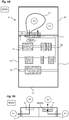
- an electrical cabinet 1 can comprise a lower wall 10, an upper wall 11 and four side walls 12 opposite in pairs. Its walls define a first closed internal volume V1 in which electrical appliances are placed.
- the electrical devices 13 can be mounted on supports, such as uprights and rails 14 adapted.
- the cabinet 1 may include a grid allowing its internal volume to exchange air with the outside or be completely sealed, especially when it is intended to be used outdoors.
- the cabinet 1 can be made of a metallic material.
- the temperature management system 2 according to the invention can be fixed on the upper wall 11 of the electrical cabinet.
- the temperature management system 2 of the invention has the particularity of being able to store hot air during hot periods to restore it during colder periods and to be able to store cold air during cold periods to restore it during warmer periods.
- the system 2 comprises a first enclosure 20 delimiting a second closed volume V2, distinct from the volume V1 of the cabinet. It could be an airtight container.
- This enclosure 20 is advantageously made of a material that is as insulating as possible from heat so as to limit as much as possible the heat exchanges between the internal space of this enclosure and the outside.
- the system 2 also includes a reservoir 21 delimiting a third closed volume, distinct from the first volume V1 and the second volume V2.
- the reservoir 21 is also made of a material guaranteeing an airtight separation of the third volume V3 from the second volume V2.
- the reservoir 21 is intended to be placed in the second volume V2 of the first enclosure 20.
- the reservoir 21 is made of a flexible material, allowing it to vary its volume from a minimum value which can be equal to zero to a maximum value corresponding to that of the second volume V2 delimited by the enclosure 20.
- the wall of this enclosure 21 is advantageously made of a material that is as insulating as possible from heat so as to limit heat exchanges with space V2 as much as possible.
- the reservoir 21 can also be made of an extensible material, like a balloon, allowing it to deflate and release the air that it will have previously stored under the sole pressure of its walls.
- the system 2 has a first air inlet / outlet I1 connected to the second volume V2 and a second air inlet / outlet I2 intended to be connected to the first volume V1 when the system 2 is fitted to the electrical cabinet 1.
- the system 2 has a third air inlet / outlet I3 connected to the third volume V3 and a fourth air inlet / outlet I4 intended to be connected to the first volume V1 when the system 2 is fitted to the electrical cabinet 2.
- All the air inlets / outlets are independent and distinct, that is to say that they do not communicate with each other.
- Each air inlet / outlet can be produced in the form of a channel opening into the closed volume considered.
- the second air inlet / outlet I2 and the fourth air inlet / outlet I4 of the system are intended to be connected to corresponding openings made on a wall of the electrical cabinet 1, for example the upper wall 11 of that -this.
- the system 2 may include a chute 22 connected to the fourth air inlet / outlet I4, said chute 22 opening out inside the volume V1 of the electrical cabinet, preferably centrally relative to the volume V1 of the cabinet in order to better diffuse / extract the air.
- System 2 also comprises first air transfer means MT1 arranged between the first air inlet / outlet I1 and the second air inlet / outlet I2 and second air transfer means MT2 arranged between the third inlet / air outlet I3 and the fourth air inlet / outlet I4.
- the first air transfer means MT1 may comprise at least one fan and be controlled to allow air transfer from the first air inlet / outlet I1 to the second air inlet / outlet I2, therefore from the second volume V2 to the first volume V1 when the system is fitted on the electrical cabinet 1, or from the second air inlet / outlet I2 to the first air inlet / outlet I1, therefore from the first volume V1 to the second volume V2 when the system 2 is adapted on the electrical cabinet 1.
- the second air transfer means MT2 may comprise at least one fan and be controlled to allow air transfer from the third air inlet / outlet I3 to the fourth air inlet / outlet I4, therefore from the third volume V3 to the first volume V1 when the system 2 is fitted on the electrical cabinet 1, or from the fourth air inlet / outlet I4 to the third air inlet / outlet I3, therefore from the first volume V1 to the third volume V3 when the system 2 is adapted on the electrical cabinet 1.
- the first air transfer means MT1 may include a first fan VENT1 arranged between the two air outlets.
- the second air transfer means MT2 may include a second fan VENT2 arranged between the two air outlets.
- the figure 3 illustrates the air exchanges carried out between the different volumes in each of the first two operating modes.
- the system 2 comprises a control and processing unit UC intended to control each operating mode of the system.
- This control and processing unit UC may in particular comprise input / output modules.
- the first air transfer means MT1 can be connected to a first output module of the control and processing unit UC and the second air transfer means MT2 can be connected to a second output module of the unit UC ordering and processing.
- the control and processing unit UC can include calculation means allowing it to determine in which operating mode the system 2 must operate.
- the second air transfer means MT2 that is to say the second fan VENT2
- the control and processing unit UC to suck the air present in the first volume V1 and transfer it to the third volume V3.
- the expansion of the reservoir 21 inside the enclosure 20 pushes the air present in the volume V2 towards the volume V1, through the first air inlet / outlet I1 and the second inlet / air outlet I2. If a fan is present between these two inputs / outputs, this can help the transfer of air from volume V2 to volume V1, but this fan remains optional. Air can be injected from volume V2 to volume V1 via said chute 22.
- the first air transfer means MT1 that is to say the first fan VENT1 are controlled by the control and processing unit UC to suck the air present in the first volume V1 and transfer it to the second volume V2.
- the air injected into the second volume V2 compresses the reservoir, forcing the air present in the third volume V3 to escape to the first volume V1, through the third air inlet / outlet I3 and the fourth air inlet / outlet I4. If a fan is present between these last two inputs / outputs, it can help transfer air from volume V3 to volume V1, but this fan remains optional.
- the system 2 can only operate with a single fan for the two operating modes MOD1, MOD2 described above.
- This one and the same ventilator VENT is in fact used alternately as first air transfer means MT1 or as second air transfer means MT2, depending on the operating mode of the system.
- this single fan VENT is used in the first operating mode MOD1 for the first transfer of air from volume V1 to volume V3 and a simple and single opening O is then used to carry out the second transfer of air from volume V2 to volume V1.
- this single fan VENT is used for the first transfer of air from volume V1 to volume V2 while said opening O is used for the second transfer of air from volume V3 to volume V1.
- the system 2 may include a plate 23 rotatably mounted on itself around an axis.
- the plate 23 has the opening O and carries the ventilator VENT which is fixed on the plate 23 in a diametrically opposite position relative to that of said opening O.
- the plate 23 is in a first angular position called at 0 ° relative to a vertical axis (X) perpendicular to its axis of rotation and located in the plane of the plate 23, this position being the reference position of the plate 23 In this first position, the plate 23 is interposed between the first air inlet / outlet I1 and the second air inlet / outlet I2 and between the third air inlet / outlet I3 and the fourth inlet / outlet air I4, preventing any air flow from passing from one volume to another.
- the system is therefore in the third operating mode MOD3, that is to say in closed mode.
- the plate 23 is in a second angular position called 90 ° (rotation in the trigonometric direction) relative to said vertical axis (X).
- the ventilator VENT is placed between the third air inlet / outlet I3 and the fourth air inlet / outlet I4 and the opening O which is diametrically opposite is therefore placed between the first inlet / outlet of air I1 and the second air inlet / outlet I2.
- the system 2 is therefore ready to operate according to the first operating mode MOD1.
- the plate 23 is in a third angular position called 180 ° relative to said vertical axis (X). In this third position, the plate 23 is interposed between the first air inlet / outlet I1 and the second air inlet / outlet I2 and between the third air inlet / outlet I3 and the fourth inlet / outlet d air I4, preventing any air flow from passing from one volume to another.
- the system is therefore in the third operating mode MOD3, that is to say in closed mode.
- the plate 23 is in a third angular position called at 270 ° relative to said vertical axis (X).
- the ventilator VENT is located opposite the first air inlet / outlet I1 and the second air inlet / outlet I2 and the opening O is located opposite the third air inlet / outlet I3 and the fourth air inlet / outlet I4.
- the system is therefore ready to operate according to the second operating mode MOD2.
- the plate 23 can be fixed on the axis of an electric motor connected to an output module of the control and processing unit UC. According to the operating mode to be applied, the control and processing unit UC controls the electric motor to rotate the plate and make it take the desired angular position.
- the control and processing unit UC can control the position of the opening with respect to the two air inlets / outlets and thus increase or reduce the air flow in a simple way.
- Air flow control can be carried out by the control and processing unit taking into account different parameters (operating mode applied, temperature (s), operating fault, etc.).
- the figure 7E thus shows an intermediate position of the plate in which the opening O is partially opposite two air inlets / outlets.
- the first transfer of air from volume V1 to volume V3 is a transfer of so-called hot air
- the second transfer of air from volume V2 to volume V1 is a so-called cold air transfer.
- the first air transfer from volume V1 to volume V2 is a so-called cold air transfer, while the second air transfer from volume V3 to volume V1 is an air transfer says hot.
- Each operating mode can be controlled according to different variants of embodiments set out below.
- At least a first period corresponds to a so-called hot time interval while at least a second period corresponds to a so-called cold time interval.
- the means of calculation of the control and processing unit consider a period T (for example equal to one day) and determines, over this period T, the variation of the temperature at which the cabinet is exposed.
- the temperature variation curve can be generated by taking into account meteorological forecast data from the place in which the electrical cabinet is installed or from meteorological data obtained for the same period, a previous year, or after a learning period. , or by any other means.
- the control and processing unit can in particular have access to a weather data server (S_MET- figure 1 ) allowing him to have the data necessary for the creation of the curve.
- the calculation means proceed as follows.
- (Tmax - e c ) corresponds to a maximum operating temperature of the devices and that (Tmin + e f ) corresponds to a minimum operating temperature of the devices.
- control and processing unit UC is brought to apply the first operating mode MOD1.
- control and processing unit UC is brought to apply the second operating mode MOD2.
- control and processing unit UC may have to apply the third operating mode.
- the system may include a TEMP temperature sensor (shown in the figure 1 ) connected to an input module of the control and processing unit UC and placed inside the electrical cabinet 1 in order to collect temperature measurement data.
- a TEMP temperature sensor shown in the figure 1
- control and processing unit US can implement regulation by comparing the temperature present in the volume V1 of the electrical cabinet with the dew temperature.
- the system can also integrate the TEMP temperature sensor connected to an input module of the control and processing unit UC and placed inside the electrical cabinet 1 in order to collect measurement data of temperature.
- the system may include a humidity sensor connected to another input module of the control and processing unit UC in order to collect the humidity measurement data inside the electrical cabinet.
- the reservoir 21 can be made of a non-elastic (or non-extensible) material or of an extensible material. In the latter case, the pressure exerted by the walls of the reservoir 21 naturally releases the air present in the reservoir during the second operating mode. In this operating mode, the only VENT fan used between volume V1 and volume V2 can even be stopped.
Landscapes
- Engineering & Computer Science (AREA)
- Aviation & Aerospace Engineering (AREA)
- Physics & Mathematics (AREA)
- Thermal Sciences (AREA)
- Microelectronics & Electronic Packaging (AREA)
- Power Engineering (AREA)
- Cooling Or The Like Of Electrical Apparatus (AREA)
- Control Of Temperature (AREA)
Applications Claiming Priority (1)
| Application Number | Priority Date | Filing Date | Title |
|---|---|---|---|
| FR1872311A FR3089384B1 (fr) | 2018-12-04 | 2018-12-04 | Système de gestion de la température dans une enveloppe électrique |
Publications (2)
| Publication Number | Publication Date |
|---|---|
| EP3664588A1 true EP3664588A1 (de) | 2020-06-10 |
| EP3664588B1 EP3664588B1 (de) | 2023-01-11 |
Family
ID=66049309
Family Applications (1)
| Application Number | Title | Priority Date | Filing Date |
|---|---|---|---|
| EP19207752.7A Active EP3664588B1 (de) | 2018-12-04 | 2019-11-07 | System zur temperatursteuerung in einer elektrischen hülle |
Country Status (4)
| Country | Link |
|---|---|
| US (1) | US11495944B2 (de) |
| EP (1) | EP3664588B1 (de) |
| ES (1) | ES2938684T3 (de) |
| FR (1) | FR3089384B1 (de) |
Citations (2)
| Publication number | Priority date | Publication date | Assignee | Title |
|---|---|---|---|---|
| EP2789220A1 (de) * | 2011-12-05 | 2014-10-15 | Schneider Electric Industries SAS | Schaltschrank mit verbesserter wärmeableitung |
| EP3093936A1 (de) * | 2015-05-11 | 2016-11-16 | Schneider Electric Industries SAS | Wärmeableitungssystem für elektrohülle |
Family Cites Families (8)
| Publication number | Priority date | Publication date | Assignee | Title |
|---|---|---|---|---|
| US6877551B2 (en) * | 2002-07-11 | 2005-04-12 | Avaya Technology Corp. | Systems and methods for weatherproof cabinets with variably cooled compartments |
| DE102005011179B4 (de) * | 2005-03-09 | 2007-07-26 | Rittal Gmbh & Co. Kg | Verfahren zum Überwachen des Kühlbetriebes in einer Geräteanordnung mit einem Aufnahmegehäuse, insbesondere einem Schaltschrank und mit einem Kühlgerät |
| GB2464354B (en) * | 2009-03-13 | 2011-06-08 | 4Energy Ltd | Equipment enclosure |
| FR3003408B1 (fr) * | 2013-03-12 | 2016-09-23 | Schneider Electric Ind Sas | Armoire electrique a dissipation thermique amelioree |
| US10015914B2 (en) * | 2015-02-05 | 2018-07-03 | Vertiv Energy Systems, Inc. | Enclosures and methods of managing heat in heat generating modules |
| FR3047328B1 (fr) * | 2016-01-29 | 2018-01-05 | Schneider Electric Industries Sas | Procede et systeme de determination du niveau d'efficacite d'un systeme de ventilation d'une enveloppe electrique |
| US10524382B2 (en) * | 2017-08-28 | 2019-12-31 | Dmytro KHACHATUROV | System and method for forced air cooling of electrical device |
| FR3089704B1 (fr) * | 2018-12-07 | 2020-11-27 | Schneider Electric Ind Sas | Bloc de ventilation pour armoire électrique |
-
2018
- 2018-12-04 FR FR1872311A patent/FR3089384B1/fr active Active
-
2019
- 2019-11-07 ES ES19207752T patent/ES2938684T3/es active Active
- 2019-11-07 EP EP19207752.7A patent/EP3664588B1/de active Active
- 2019-11-26 US US16/695,312 patent/US11495944B2/en active Active
Patent Citations (2)
| Publication number | Priority date | Publication date | Assignee | Title |
|---|---|---|---|---|
| EP2789220A1 (de) * | 2011-12-05 | 2014-10-15 | Schneider Electric Industries SAS | Schaltschrank mit verbesserter wärmeableitung |
| EP3093936A1 (de) * | 2015-05-11 | 2016-11-16 | Schneider Electric Industries SAS | Wärmeableitungssystem für elektrohülle |
Also Published As
| Publication number | Publication date |
|---|---|
| RU2019139043A (ru) | 2021-06-03 |
| US11495944B2 (en) | 2022-11-08 |
| FR3089384A1 (fr) | 2020-06-05 |
| FR3089384B1 (fr) | 2020-10-30 |
| ES2938684T3 (es) | 2023-04-13 |
| US20200176958A1 (en) | 2020-06-04 |
| EP3664588B1 (de) | 2023-01-11 |
Similar Documents
| Publication | Publication Date | Title |
|---|---|---|
| EP2779335B1 (de) | Schaltschrank mit verbesserter Wärmeableitung | |
| EP3467605B1 (de) | Überwachungsverfahren eines systems zur temperaturregulierung, das zu einem schaltschrank gehört | |
| EP2553345B1 (de) | Vorrichtung zur analyse des wärmeverhaltens im übergangszustand eines raums mit einer heiz- oder klimaanlage | |
| FR2806036A1 (fr) | Regulation perfectionnee de la temperature, de la vitesse et de la distribution de l'air ventile dans un habitacle de vehicule automobile | |
| WO2015101751A1 (fr) | Procédé et dispositif de détermination du coefficient de déperdition thermique d'un local | |
| FR3025871B1 (fr) | Equipement de controle d'au moins un appareil de regulation thermique, et ensemble de regulation et systeme de pilotage associes | |
| EP3664588B1 (de) | System zur temperatursteuerung in einer elektrischen hülle | |
| EP3087447B1 (de) | Verfahren zur prognose eines inneren komfortparameters und zugehöriges endgerät | |
| EP3090112B1 (de) | Verfahren zur bedienung eines fensters und eines haustechniksystems eines gebäudes | |
| WO2013102578A2 (fr) | Dispositif d'analyse thermique | |
| EP0852331B1 (de) | Verfahren zur Messung des Volumenkoeffizienten von Wärmeverlusten eines elektrisch geheizten Raumes | |
| FR3036233A1 (fr) | Systeme de dissipation thermique pour enveloppe electrique | |
| FR3104750A1 (fr) | Système de régulation de la température et/ou de la luminosité d’un local équipé de vitrages activables par courant électrique | |
| FR2739931A1 (fr) | Procede et dispositif pour mesurer le coefficient volumique de deperdition thermique d'un local chauffe electriquement | |
| FR2724576A1 (fr) | Systeme assecheur d'air | |
| EP4632524A1 (de) | Vorrichtung zur verbindung mit einem gebäudeheizregler | |
| RU2795699C2 (ru) | Система управления температурой в электрическом кожухе | |
| EP2869028A1 (de) | Verfahren zur Konfiguration einer Lese- und Aufzeichnungsvorrichtung für Impulse, die eine Lesung mindestens eines Impulse aussendenden Zählers ausführen soll, und entsprechende Vorrichtung | |
| EP2979146B1 (de) | Steuerungsvorrichtung für eine heizungs-, lüftungs- und klimaanlagenmaschine | |
| CA2120886A1 (fr) | Dispositif de chauffage pour radiateur a eau ou autre liquide coloporteur | |
| WO1981003060A1 (fr) | Procede de regulation d'un appareil de chauffage et appareil de chauffage regule par ce procede | |
| FR3032277A1 (fr) | Procede d'estimation d'une consommation electrique d'un equipement | |
| FR3149677A1 (fr) | Ensemble de casiers régulés individuellement en température | |
| CH342010A (fr) | Procédé pour intégrer la capacité d'absorption de chaleur d'un milieu et appareil pour la mise en oeuvre de ce procédé | |
| WO2018215631A1 (fr) | Dispositif de commande et de regulation d'un circuit chauffant de balai d'essui-glace |
Legal Events
| Date | Code | Title | Description |
|---|---|---|---|
| PUAI | Public reference made under article 153(3) epc to a published international application that has entered the european phase |
Free format text: ORIGINAL CODE: 0009012 |
|
| STAA | Information on the status of an ep patent application or granted ep patent |
Free format text: STATUS: THE APPLICATION HAS BEEN PUBLISHED |
|
| AK | Designated contracting states |
Kind code of ref document: A1 Designated state(s): AL AT BE BG CH CY CZ DE DK EE ES FI FR GB GR HR HU IE IS IT LI LT LU LV MC MK MT NL NO PL PT RO RS SE SI SK SM TR |
|
| AX | Request for extension of the european patent |
Extension state: BA ME |
|
| STAA | Information on the status of an ep patent application or granted ep patent |
Free format text: STATUS: REQUEST FOR EXAMINATION WAS MADE |
|
| 17P | Request for examination filed |
Effective date: 20200721 |
|
| RBV | Designated contracting states (corrected) |
Designated state(s): AL AT BE BG CH CY CZ DE DK EE ES FI FR GB GR HR HU IE IS IT LI LT LU LV MC MK MT NL NO PL PT RO RS SE SI SK SM TR |
|
| GRAP | Despatch of communication of intention to grant a patent |
Free format text: ORIGINAL CODE: EPIDOSNIGR1 |
|
| STAA | Information on the status of an ep patent application or granted ep patent |
Free format text: STATUS: GRANT OF PATENT IS INTENDED |
|
| RIC1 | Information provided on ipc code assigned before grant |
Ipc: H02B 1/56 20060101ALI20220906BHEP Ipc: H05K 7/20 20060101AFI20220906BHEP |
|
| INTG | Intention to grant announced |
Effective date: 20220923 |
|
| GRAS | Grant fee paid |
Free format text: ORIGINAL CODE: EPIDOSNIGR3 |
|
| GRAA | (expected) grant |
Free format text: ORIGINAL CODE: 0009210 |
|
| STAA | Information on the status of an ep patent application or granted ep patent |
Free format text: STATUS: THE PATENT HAS BEEN GRANTED |
|
| AK | Designated contracting states |
Kind code of ref document: B1 Designated state(s): AL AT BE BG CH CY CZ DE DK EE ES FI FR GB GR HR HU IE IS IT LI LT LU LV MC MK MT NL NO PL PT RO RS SE SI SK SM TR |
|
| REG | Reference to a national code |
Ref country code: GB Ref legal event code: FG4D Free format text: NOT ENGLISH |
|
| REG | Reference to a national code |
Ref country code: CH Ref legal event code: EP |
|
| REG | Reference to a national code |
Ref country code: DE Ref legal event code: R096 Ref document number: 602019024243 Country of ref document: DE |
|
| REG | Reference to a national code |
Ref country code: IE Ref legal event code: FG4D Free format text: LANGUAGE OF EP DOCUMENT: FRENCH |
|
| REG | Reference to a national code |
Ref country code: AT Ref legal event code: REF Ref document number: 1544183 Country of ref document: AT Kind code of ref document: T Effective date: 20230215 |
|
| REG | Reference to a national code |
Ref country code: ES Ref legal event code: FG2A Ref document number: 2938684 Country of ref document: ES Kind code of ref document: T3 Effective date: 20230413 |
|
| REG | Reference to a national code |
Ref country code: LT Ref legal event code: MG9D |
|
| REG | Reference to a national code |
Ref country code: NL Ref legal event code: MP Effective date: 20230111 |
|
| REG | Reference to a national code |
Ref country code: AT Ref legal event code: MK05 Ref document number: 1544183 Country of ref document: AT Kind code of ref document: T Effective date: 20230111 |
|
| PG25 | Lapsed in a contracting state [announced via postgrant information from national office to epo] |
Ref country code: NL Free format text: LAPSE BECAUSE OF FAILURE TO SUBMIT A TRANSLATION OF THE DESCRIPTION OR TO PAY THE FEE WITHIN THE PRESCRIBED TIME-LIMIT Effective date: 20230111 |
|
| PG25 | Lapsed in a contracting state [announced via postgrant information from national office to epo] |
Ref country code: RS Free format text: LAPSE BECAUSE OF FAILURE TO SUBMIT A TRANSLATION OF THE DESCRIPTION OR TO PAY THE FEE WITHIN THE PRESCRIBED TIME-LIMIT Effective date: 20230111 Ref country code: PT Free format text: LAPSE BECAUSE OF FAILURE TO SUBMIT A TRANSLATION OF THE DESCRIPTION OR TO PAY THE FEE WITHIN THE PRESCRIBED TIME-LIMIT Effective date: 20230511 Ref country code: NO Free format text: LAPSE BECAUSE OF FAILURE TO SUBMIT A TRANSLATION OF THE DESCRIPTION OR TO PAY THE FEE WITHIN THE PRESCRIBED TIME-LIMIT Effective date: 20230411 Ref country code: LV Free format text: LAPSE BECAUSE OF FAILURE TO SUBMIT A TRANSLATION OF THE DESCRIPTION OR TO PAY THE FEE WITHIN THE PRESCRIBED TIME-LIMIT Effective date: 20230111 Ref country code: LT Free format text: LAPSE BECAUSE OF FAILURE TO SUBMIT A TRANSLATION OF THE DESCRIPTION OR TO PAY THE FEE WITHIN THE PRESCRIBED TIME-LIMIT Effective date: 20230111 Ref country code: HR Free format text: LAPSE BECAUSE OF FAILURE TO SUBMIT A TRANSLATION OF THE DESCRIPTION OR TO PAY THE FEE WITHIN THE PRESCRIBED TIME-LIMIT Effective date: 20230111 Ref country code: AT Free format text: LAPSE BECAUSE OF FAILURE TO SUBMIT A TRANSLATION OF THE DESCRIPTION OR TO PAY THE FEE WITHIN THE PRESCRIBED TIME-LIMIT Effective date: 20230111 |
|
| PG25 | Lapsed in a contracting state [announced via postgrant information from national office to epo] |
Ref country code: SE Free format text: LAPSE BECAUSE OF FAILURE TO SUBMIT A TRANSLATION OF THE DESCRIPTION OR TO PAY THE FEE WITHIN THE PRESCRIBED TIME-LIMIT Effective date: 20230111 Ref country code: PL Free format text: LAPSE BECAUSE OF FAILURE TO SUBMIT A TRANSLATION OF THE DESCRIPTION OR TO PAY THE FEE WITHIN THE PRESCRIBED TIME-LIMIT Effective date: 20230111 Ref country code: IS Free format text: LAPSE BECAUSE OF FAILURE TO SUBMIT A TRANSLATION OF THE DESCRIPTION OR TO PAY THE FEE WITHIN THE PRESCRIBED TIME-LIMIT Effective date: 20230511 Ref country code: GR Free format text: LAPSE BECAUSE OF FAILURE TO SUBMIT A TRANSLATION OF THE DESCRIPTION OR TO PAY THE FEE WITHIN THE PRESCRIBED TIME-LIMIT Effective date: 20230412 Ref country code: FI Free format text: LAPSE BECAUSE OF FAILURE TO SUBMIT A TRANSLATION OF THE DESCRIPTION OR TO PAY THE FEE WITHIN THE PRESCRIBED TIME-LIMIT Effective date: 20230111 |
|
| REG | Reference to a national code |
Ref country code: DE Ref legal event code: R097 Ref document number: 602019024243 Country of ref document: DE |
|
| PG25 | Lapsed in a contracting state [announced via postgrant information from national office to epo] |
Ref country code: SM Free format text: LAPSE BECAUSE OF FAILURE TO SUBMIT A TRANSLATION OF THE DESCRIPTION OR TO PAY THE FEE WITHIN THE PRESCRIBED TIME-LIMIT Effective date: 20230111 Ref country code: RO Free format text: LAPSE BECAUSE OF FAILURE TO SUBMIT A TRANSLATION OF THE DESCRIPTION OR TO PAY THE FEE WITHIN THE PRESCRIBED TIME-LIMIT Effective date: 20230111 Ref country code: EE Free format text: LAPSE BECAUSE OF FAILURE TO SUBMIT A TRANSLATION OF THE DESCRIPTION OR TO PAY THE FEE WITHIN THE PRESCRIBED TIME-LIMIT Effective date: 20230111 Ref country code: DK Free format text: LAPSE BECAUSE OF FAILURE TO SUBMIT A TRANSLATION OF THE DESCRIPTION OR TO PAY THE FEE WITHIN THE PRESCRIBED TIME-LIMIT Effective date: 20230111 Ref country code: CZ Free format text: LAPSE BECAUSE OF FAILURE TO SUBMIT A TRANSLATION OF THE DESCRIPTION OR TO PAY THE FEE WITHIN THE PRESCRIBED TIME-LIMIT Effective date: 20230111 |
|
| PLBE | No opposition filed within time limit |
Free format text: ORIGINAL CODE: 0009261 |
|
| STAA | Information on the status of an ep patent application or granted ep patent |
Free format text: STATUS: NO OPPOSITION FILED WITHIN TIME LIMIT |
|
| PG25 | Lapsed in a contracting state [announced via postgrant information from national office to epo] |
Ref country code: SK Free format text: LAPSE BECAUSE OF FAILURE TO SUBMIT A TRANSLATION OF THE DESCRIPTION OR TO PAY THE FEE WITHIN THE PRESCRIBED TIME-LIMIT Effective date: 20230111 |
|
| 26N | No opposition filed |
Effective date: 20231012 |
|
| PG25 | Lapsed in a contracting state [announced via postgrant information from national office to epo] |
Ref country code: SI Free format text: LAPSE BECAUSE OF FAILURE TO SUBMIT A TRANSLATION OF THE DESCRIPTION OR TO PAY THE FEE WITHIN THE PRESCRIBED TIME-LIMIT Effective date: 20230111 |
|
| REG | Reference to a national code |
Ref country code: DE Ref legal event code: R119 Ref document number: 602019024243 Country of ref document: DE |
|
| REG | Reference to a national code |
Ref country code: CH Ref legal event code: PL |
|
| PG25 | Lapsed in a contracting state [announced via postgrant information from national office to epo] |
Ref country code: MC Free format text: LAPSE BECAUSE OF FAILURE TO SUBMIT A TRANSLATION OF THE DESCRIPTION OR TO PAY THE FEE WITHIN THE PRESCRIBED TIME-LIMIT Effective date: 20230111 |
|
| PG25 | Lapsed in a contracting state [announced via postgrant information from national office to epo] |
Ref country code: LU Free format text: LAPSE BECAUSE OF NON-PAYMENT OF DUE FEES Effective date: 20231107 |
|
| PG25 | Lapsed in a contracting state [announced via postgrant information from national office to epo] |
Ref country code: CH Free format text: LAPSE BECAUSE OF NON-PAYMENT OF DUE FEES Effective date: 20231130 |
|
| GBPC | Gb: european patent ceased through non-payment of renewal fee |
Effective date: 20231107 |
|
| PG25 | Lapsed in a contracting state [announced via postgrant information from national office to epo] |
Ref country code: MC Free format text: LAPSE BECAUSE OF FAILURE TO SUBMIT A TRANSLATION OF THE DESCRIPTION OR TO PAY THE FEE WITHIN THE PRESCRIBED TIME-LIMIT Effective date: 20230111 Ref country code: LU Free format text: LAPSE BECAUSE OF NON-PAYMENT OF DUE FEES Effective date: 20231107 Ref country code: CH Free format text: LAPSE BECAUSE OF NON-PAYMENT OF DUE FEES Effective date: 20231130 |
|
| REG | Reference to a national code |
Ref country code: BE Ref legal event code: MM Effective date: 20231130 |
|
| REG | Reference to a national code |
Ref country code: IE Ref legal event code: MM4A |
|
| PG25 | Lapsed in a contracting state [announced via postgrant information from national office to epo] |
Ref country code: IE Free format text: LAPSE BECAUSE OF NON-PAYMENT OF DUE FEES Effective date: 20231107 Ref country code: DE Free format text: LAPSE BECAUSE OF NON-PAYMENT OF DUE FEES Effective date: 20240601 |
|
| PG25 | Lapsed in a contracting state [announced via postgrant information from national office to epo] |
Ref country code: GB Free format text: LAPSE BECAUSE OF NON-PAYMENT OF DUE FEES Effective date: 20231107 |
|
| PG25 | Lapsed in a contracting state [announced via postgrant information from national office to epo] |
Ref country code: BE Free format text: LAPSE BECAUSE OF NON-PAYMENT OF DUE FEES Effective date: 20231130 |
|
| PG25 | Lapsed in a contracting state [announced via postgrant information from national office to epo] |
Ref country code: IE Free format text: LAPSE BECAUSE OF NON-PAYMENT OF DUE FEES Effective date: 20231107 Ref country code: GB Free format text: LAPSE BECAUSE OF NON-PAYMENT OF DUE FEES Effective date: 20231107 Ref country code: DE Free format text: LAPSE BECAUSE OF NON-PAYMENT OF DUE FEES Effective date: 20240601 Ref country code: BE Free format text: LAPSE BECAUSE OF NON-PAYMENT OF DUE FEES Effective date: 20231130 |
|
| PG25 | Lapsed in a contracting state [announced via postgrant information from national office to epo] |
Ref country code: BG Free format text: LAPSE BECAUSE OF FAILURE TO SUBMIT A TRANSLATION OF THE DESCRIPTION OR TO PAY THE FEE WITHIN THE PRESCRIBED TIME-LIMIT Effective date: 20230111 |
|
| PG25 | Lapsed in a contracting state [announced via postgrant information from national office to epo] |
Ref country code: BG Free format text: LAPSE BECAUSE OF FAILURE TO SUBMIT A TRANSLATION OF THE DESCRIPTION OR TO PAY THE FEE WITHIN THE PRESCRIBED TIME-LIMIT Effective date: 20230111 |
|
| PGFP | Annual fee paid to national office [announced via postgrant information from national office to epo] |
Ref country code: IT Payment date: 20241125 Year of fee payment: 6 |
|
| PG25 | Lapsed in a contracting state [announced via postgrant information from national office to epo] |
Ref country code: CY Free format text: LAPSE BECAUSE OF FAILURE TO SUBMIT A TRANSLATION OF THE DESCRIPTION OR TO PAY THE FEE WITHIN THE PRESCRIBED TIME-LIMIT; INVALID AB INITIO Effective date: 20191107 |
|
| PG25 | Lapsed in a contracting state [announced via postgrant information from national office to epo] |
Ref country code: HU Free format text: LAPSE BECAUSE OF FAILURE TO SUBMIT A TRANSLATION OF THE DESCRIPTION OR TO PAY THE FEE WITHIN THE PRESCRIBED TIME-LIMIT; INVALID AB INITIO Effective date: 20191107 |
|
| PG25 | Lapsed in a contracting state [announced via postgrant information from national office to epo] |
Ref country code: TR Free format text: LAPSE BECAUSE OF FAILURE TO SUBMIT A TRANSLATION OF THE DESCRIPTION OR TO PAY THE FEE WITHIN THE PRESCRIBED TIME-LIMIT Effective date: 20230111 |
|
| PGFP | Annual fee paid to national office [announced via postgrant information from national office to epo] |
Ref country code: FR Payment date: 20251124 Year of fee payment: 7 |
|
| PGFP | Annual fee paid to national office [announced via postgrant information from national office to epo] |
Ref country code: ES Payment date: 20260127 Year of fee payment: 7 |