EP3664442A1 - Method and device for image transmission, movable platform, monitoring device, and system - Google Patents
Method and device for image transmission, movable platform, monitoring device, and system Download PDFInfo
- Publication number
- EP3664442A1 EP3664442A1 EP17924888.5A EP17924888A EP3664442A1 EP 3664442 A1 EP3664442 A1 EP 3664442A1 EP 17924888 A EP17924888 A EP 17924888A EP 3664442 A1 EP3664442 A1 EP 3664442A1
- Authority
- EP
- European Patent Office
- Prior art keywords
- image
- bit
- movable platform
- monitoring device
- data
- Prior art date
- Legal status (The legal status is an assumption and is not a legal conclusion. Google has not performed a legal analysis and makes no representation as to the accuracy of the status listed.)
- Ceased
Links
- 238000012806 monitoring device Methods 0.000 title claims abstract description 139
- 238000000034 method Methods 0.000 title claims abstract description 95
- 230000005540 biological transmission Effects 0.000 title claims abstract description 68
- 238000012545 processing Methods 0.000 claims abstract description 34
- 238000004891 communication Methods 0.000 claims description 35
- 239000011521 glass Substances 0.000 claims description 4
- 238000012544 monitoring process Methods 0.000 abstract description 13
- 238000010586 diagram Methods 0.000 description 17
- 230000015572 biosynthetic process Effects 0.000 description 7
- 230000000007 visual effect Effects 0.000 description 6
- 230000006870 function Effects 0.000 description 4
- 238000003786 synthesis reaction Methods 0.000 description 4
- 230000008878 coupling Effects 0.000 description 3
- 238000010168 coupling process Methods 0.000 description 3
- 238000005859 coupling reaction Methods 0.000 description 3
- 238000005516 engineering process Methods 0.000 description 2
- 238000003384 imaging method Methods 0.000 description 2
- 238000012986 modification Methods 0.000 description 1
- 230000004048 modification Effects 0.000 description 1
- 230000003287 optical effect Effects 0.000 description 1
- 238000006467 substitution reaction Methods 0.000 description 1
- 238000001308 synthesis method Methods 0.000 description 1
Images


Classifications
-
- H—ELECTRICITY
- H04—ELECTRIC COMMUNICATION TECHNIQUE
- H04N—PICTORIAL COMMUNICATION, e.g. TELEVISION
- H04N7/00—Television systems
- H04N7/18—Closed-circuit television [CCTV] systems, i.e. systems in which the video signal is not broadcast
-
- G—PHYSICS
- G06—COMPUTING; CALCULATING OR COUNTING
- G06T—IMAGE DATA PROCESSING OR GENERATION, IN GENERAL
- G06T15/00—3D [Three Dimensional] image rendering
- G06T15/08—Volume rendering
-
- G—PHYSICS
- G06—COMPUTING; CALCULATING OR COUNTING
- G06T—IMAGE DATA PROCESSING OR GENERATION, IN GENERAL
- G06T1/00—General purpose image data processing
- G06T1/0007—Image acquisition
-
- G—PHYSICS
- G06—COMPUTING; CALCULATING OR COUNTING
- G06T—IMAGE DATA PROCESSING OR GENERATION, IN GENERAL
- G06T5/00—Image enhancement or restoration
- G06T5/50—Image enhancement or restoration using two or more images, e.g. averaging or subtraction
-
- H—ELECTRICITY
- H04—ELECTRIC COMMUNICATION TECHNIQUE
- H04N—PICTORIAL COMMUNICATION, e.g. TELEVISION
- H04N13/00—Stereoscopic video systems; Multi-view video systems; Details thereof
- H04N13/10—Processing, recording or transmission of stereoscopic or multi-view image signals
- H04N13/194—Transmission of image signals
-
- H—ELECTRICITY
- H04—ELECTRIC COMMUNICATION TECHNIQUE
- H04N—PICTORIAL COMMUNICATION, e.g. TELEVISION
- H04N13/00—Stereoscopic video systems; Multi-view video systems; Details thereof
- H04N13/20—Image signal generators
- H04N13/204—Image signal generators using stereoscopic image cameras
- H04N13/239—Image signal generators using stereoscopic image cameras using two 2D image sensors having a relative position equal to or related to the interocular distance
-
- H—ELECTRICITY
- H04—ELECTRIC COMMUNICATION TECHNIQUE
- H04N—PICTORIAL COMMUNICATION, e.g. TELEVISION
- H04N23/00—Cameras or camera modules comprising electronic image sensors; Control thereof
- H04N23/60—Control of cameras or camera modules
-
- H—ELECTRICITY
- H04—ELECTRIC COMMUNICATION TECHNIQUE
- H04N—PICTORIAL COMMUNICATION, e.g. TELEVISION
- H04N7/00—Television systems
- H04N7/18—Closed-circuit television [CCTV] systems, i.e. systems in which the video signal is not broadcast
- H04N7/181—Closed-circuit television [CCTV] systems, i.e. systems in which the video signal is not broadcast for receiving images from a plurality of remote sources
-
- H—ELECTRICITY
- H04—ELECTRIC COMMUNICATION TECHNIQUE
- H04N—PICTORIAL COMMUNICATION, e.g. TELEVISION
- H04N7/00—Television systems
- H04N7/18—Closed-circuit television [CCTV] systems, i.e. systems in which the video signal is not broadcast
- H04N7/183—Closed-circuit television [CCTV] systems, i.e. systems in which the video signal is not broadcast for receiving images from a single remote source
- H04N7/185—Closed-circuit television [CCTV] systems, i.e. systems in which the video signal is not broadcast for receiving images from a single remote source from a mobile camera, e.g. for remote control
-
- B—PERFORMING OPERATIONS; TRANSPORTING
- B60—VEHICLES IN GENERAL
- B60R—VEHICLES, VEHICLE FITTINGS, OR VEHICLE PARTS, NOT OTHERWISE PROVIDED FOR
- B60R2300/00—Details of viewing arrangements using cameras and displays, specially adapted for use in a vehicle
- B60R2300/10—Details of viewing arrangements using cameras and displays, specially adapted for use in a vehicle characterised by the type of camera system used
- B60R2300/107—Details of viewing arrangements using cameras and displays, specially adapted for use in a vehicle characterised by the type of camera system used using stereoscopic cameras
-
- B—PERFORMING OPERATIONS; TRANSPORTING
- B64—AIRCRAFT; AVIATION; COSMONAUTICS
- B64U—UNMANNED AERIAL VEHICLES [UAV]; EQUIPMENT THEREFOR
- B64U2101/00—UAVs specially adapted for particular uses or applications
- B64U2101/30—UAVs specially adapted for particular uses or applications for imaging, photography or videography
-
- G—PHYSICS
- G06—COMPUTING; CALCULATING OR COUNTING
- G06T—IMAGE DATA PROCESSING OR GENERATION, IN GENERAL
- G06T2207/00—Indexing scheme for image analysis or image enhancement
- G06T2207/10—Image acquisition modality
- G06T2207/10032—Satellite or aerial image; Remote sensing
-
- G—PHYSICS
- G06—COMPUTING; CALCULATING OR COUNTING
- G06T—IMAGE DATA PROCESSING OR GENERATION, IN GENERAL
- G06T2207/00—Indexing scheme for image analysis or image enhancement
- G06T2207/20—Special algorithmic details
- G06T2207/20212—Image combination
- G06T2207/20221—Image fusion; Image merging
Definitions
- the present disclosure generally relates to the field of unmanned aerial vehicles and, more particularly, relates to a method and a device for image transmission, movable platform, and monitoring device and system.
- a movable platform such as an unmanned aerial vehicle, a model airplane, a remote-control vehicle, a remote-control boat, a movable robot, etc. can be equipped with a photographing device. Further, the movable platform transmits an image or video captured by the photographing device to a remote monitoring device through a communication system.
- the movable platform sends a two-dimensional image or video to the remote monitoring device, so that the remote monitoring device displays a two-dimensional image. That is, the picture seen by a user that holds the monitoring device is a two-dimensional image.
- Embodiments of the present disclosure provide an image transmission method, a device, a movable platform, and a monitoring device and system, so as to improve the accuracy of remote monitoring of a movable platform.
- a first aspect of the embodiments of the present disclosure provides an image transmission method, including:
- a second aspect of the embodiments of the present disclosure provides an image transmission method, including:
- a third aspect of the embodiments of the present disclosure provides an image transmission device, including a first communication interface, and a first processor, where:
- a fourth aspect of the embodiments of the present disclosure provides a movable platform, including:
- a fifth aspect of the embodiments of the present disclosure provides a monitoring device, including a second communication interface, a second processor, a first display device, and a second display device, where: the second communication interface is configured to:
- a sixth aspect of the embodiments of the present disclosure provides a monitoring device, including a movable platform provided by the fourth aspect; and a monitoring device provided by the fifth aspect.
- An image transmission method, a device, a movable platform, and a monitoring device and system are able to acquire two images captured by two photographing devices mounted on the movable platform at the same time, and perform image processing on the two images to obtain image data.
- the image data is sent to the monitoring device, and the monitoring device restores the two images based on the image data and displays an image by each of the two display devices, such that the picture on a monitor screen observed by the user through the two display devices is more in line with the visual characteristics of the human eye, and thus lack of parallax information or depth information in the picture on the monitor screen can be avoided.
- the user may be able to accurately determine the farness and/or nearness of the objects in the picture on the monitor screen, and thus the accuracy of remote monitoring of the movable platform may be improved.
- a component when referred to as being "fixed” to another component, it can be directly on the other component or an intermediate component may be present. When a component is considered as "connected to" another component, it can be directly connected to another component or both may be connected to an intermediate component.
- FIG. 1 illustrates a flowchart of an image transmission method according to an embodiment of the present disclosure. As shown in FIG. 1 , the method in one embodiment may include:
- the image transmission method described in one embodiment is applicable to a movable platform and a corresponding monitoring device thereof, and the movable platform includes at least one of the following: an unmanned aerial vehicle (UAV), a movable robot, a model airplane, a remote-control vehicle, or a remote-control boat.
- UAV unmanned aerial vehicle
- a movable robot a model airplane
- a remote-control vehicle a remote-control boat.
- a UAV is taken as an example to illustrate the image transmission process between the UAV and a ground monitoring device.
- a UAV 20 is equipped with a first photographing device 21 and a second photographing device 22.
- the first photographing device 21 may be, for example, a camera
- the second photographing device 22 may be, for example, another camera.
- a processor 23 is communicatively connected to the first photographing device 21 and the second photographing device 22, and the processor 23 may be able to control the first photographing device 21 and the second photographing device 22 to take image information at the same time.
- the method of this embodiment may be executed by a processor in a movable platform.
- the processor may be other general purpose or dedicated processors, and the processor may have image processing functions.
- the processor 23 may be able to acquire the image information captured by the first photographing device 21 and the second photographing device 22 at the same time.
- the image information captured by the first photographing device 21 may be denoted as a first image
- the image information captured by the second photographing device 22 may be denoted as a second image.
- the processor 23 may further be able to control the photographing parameters of the first photographing device 21 and the second photographing device 22, such that the photographing parameters for the first image captured by the first photographing device 21 and the second image captured by the second photographing device 22 are the same.
- the photographing parameters may include at least one of the following: an exposure time, a shutter speed, or an aperture size.
- the processor 23 may perform image processing on the first image and the second image to obtain image-processed image data.
- an implementation method for performing image processing on the first image and the second image to obtain image-processed image data includes: combining the first image and the second image into a target image; and encoding the target image to obtain encoded image data.
- 31 denotes the first image captured by the first photographing device 21
- 32 denotes the second image captured by the second photographing device 22
- the processor 23 may first combine the first image 31 and the second image 32 into a target image 33.
- the target image 33 may be encoded to obtain encoded image data 34.
- combining the first image and the second image into the target image may include the following possible implementation methods.
- a possible implementation method includes: splicing the first image and the second image left and right to obtain the target image.
- the first image 31 may be spliced to the left side of the second image 32 to obtain the spliced target image 33.
- the first image 31 may be spliced to the right side of the second image 32 to obtain the spliced target image 33.
- Another possible implementation method includes: splicing the first image and the second image up and down to obtain the target image.
- the first image 31 may be spliced on the upper side of the second image 32 to obtain the spliced target image 33.
- the first image 31 may be spliced on the lower side of the second image 32 to obtain the spliced target image 33.
- the splicing methods shown in FIG. 4 to FIG. 7 are only illustrative and not specifically limited. In other embodiments, other image synthesis methods may be included.
- S103 sending the image-processed image data to a monitoring device, so that the monitoring device determines the first image and the second image based on the image data, and displays the first image through a first display device and displays the second image through a second display device.
- the processor 23 may transmit the image data 34 processed from the first image 31 and the second image 32 to a ground monitoring device 25 through a communication system 24 of the UAV 20.
- the monitoring device 25 may receive the image data sent by the UAV 20 through an antenna 114.
- the monitoring device 25 may include at least one of the following: a remote controller, a user terminal device, or headwear glasses. Alternatively, the monitoring device 25 can also be a wearable device.
- the processor 26 of the monitoring device 25 may first decode the encoded image data 34 to obtain the target image 33, further decompose the target image 33 to obtain the first image 31 and the second image 32, and may display the first image 31 through a first display device 27 and display the second image 32 through a second display device 28, or display the second image 32 through the first display device 27 and display the first image 31 through the second display device 28.
- the first display device 27 may be, for example, a display screen
- the second display device 28 may be, for example, another display screen.
- the first display device 27 and the second display device 28 may be disposed on the monitoring device 25.
- the first display device 27 and the second display device 28 may be external devices of the monitoring device 25, and the first display device 27 and the second display device 28 may be communicatively connected to the monitoring device 25, respectively, as shown in FIG. 9 .
- two images captured at the same time respectively by two photographing devices mounted on a movable platform are acquired, image processing is performed on the two images to obtain image data, the image data is sent to a monitoring device, and the monitoring device restores the two images based on the image data and displays one image through each of two display devices, such that the picture on a monitor screen observed by the user through the two display devices is more in line with the visual characteristics of the human eye, and thus lack of parallax information or depth information in the picture on the monitor screen can be avoided.
- the user may be able to accurately determine the farness and/or nearness of objects in the picture on the monitor screen, and thus the accuracy of remote monitoring of the movable platform may be improved.
- FIG. 10 illustrates a flowchart of an image transmission method according to another embodiment of the present disclosure.
- another implementation method for performing image processing on the first image and the second image to obtain image-processed image data in S 102 may include the following steps.
- the processor 23 may number the first image captured by the first photographing device 21 and the second image captured by the second photographing device 22, respectively.
- the first image number may be 001
- the second image number may be 002.
- the processor 23 may encode the first image and the first image number to obtain encoded first bit-stream data 110.
- the processor 23 may encode the second image and the second image number to obtain encoded second bit-stream data 111.
- S103 of sending the image-processed image data to the monitoring device may include S1031 shown in FIG. 10 : sending the encoded first bit-stream data and the encoded second bit-stream data to the monitoring device.
- the processor 23 may send the encoded first bit-stream data 110 and the encoded second bit-stream data 111 to the ground monitoring device 25 through the communication system 24 of the UAV 20.
- the communication system 24 may send the encoded first bit-stream data 110 and the encoded second bit-stream data 111 to the monitoring device 25 in a predetermined order, e.g. a coding order.
- the encoded first bit-stream data is obtained after encoding the first image and the first image number
- the encoded second bit-stream data is obtained after encoding the second image and the second image number.
- the embodiments of the present disclosure provide an image transmission method. Based on the embodiments described above, the method may further include: controlling the photographing parameters of the first photographing device and the second photographing device. As shown in FIG. 2 , the processor 23 of the UAV 20 may also be able to control the photographing parameters of the first photographing device 21 and the second photographing device 22.
- the photographing parameters may include at least one of the following: an exposure time, a shutter speed, or an aperture size.
- the first image and the second image may be captured at the same time, and the photographing parameters of the first image and the second image may be the same.
- the relative position of the first photographing device and the second photographing device maybe determined by simulating the relative position of the human eyes.
- the first photographing device and the second photographing device may be disposed at a same level on the movable platform.
- the first photographing device 21 and the second photographing device 22 may be disposed on the UAV 20 at a same level.
- first photographing device and the second photographing device may be used to acquire a three-dimensional image.
- the method may also include sending the three-dimensional image to a monitoring device so that the monitoring device displays the three-dimensional image through the first display device and the second display device.
- the processor 23 may also be able to send the three-dimensional image acquired by the first photographing device 21 and the second photographing device 22 to the ground monitoring device 25 through the communication system 24 of the UAV 20.
- the monitoring device 25 receives the three-dimensional image, as shown in FIG. 8 or FIG. 9 , the three-dimensional image may be displayed through the first display device 27 and the second display device 28.
- a three-dimensional image may be acquired by the first photographing device and the second photographing device, and the three-dimensional image may be sent to a ground monitoring device.
- the three-dimensional image may be able to provide a more realistic and natural picture on the monitor screen to the user, so that the user may be able to accurately determine the farness and/or nearness of objects in the picture on the monitor screen, and thus the accuracy of remote monitoring of the movable platform may be improved.
- FIG. 12 illustrates a schematic flowchart of an image transmission method according to another embodiment of the present disclosure.
- the method may be executed by a monitoring device. As shown in FIG. 12 , the method in this embodiment may include:
- the image data may be obtained after the movable platform performs image processing on a first image captured by a first photographing device and a second image captured by a second photographing device.
- the first photographing device and the second photographing device are mounted on the movable platform, and the first image and the second image are captured at the same time.
- the UAV 20 may be equipped with a first photographing device 21 and a second photographing device 22.
- the first photographing device 21 may be, for example, a camera
- the second photographing device 22 may be, for example, another camera.
- the processor 23 of the UAV 20 may be able to acquire a first image captured by the first photographing device 21 and a second image captured by the second photographing device 22 at the same time. Further, the processor 23 may perform image processing on the first image and the second image to obtain image-processed image data.
- the image data may be sent to a ground monitoring device 25 through the communication system 24 of the UAV 20, and the monitoring device 25 may receive the image data sent by the UAV 20 through the antenna 114.
- the image data is encoded image data obtained after the movable platform combines the first image and the second image to a target image and encodes the target image.
- determining the first image and the second image based on the image data may include: decoding the encoded image data to obtain the target image; and decomposing the target image into the first image and the second image.
- 31 denotes a first image captured by a first photographing device 21
- 32 denotes a second image photographed by a second photographing device 22
- the processor 23 may first combine the first image 31 and the second image 32 into a target image 33.
- the target image 33 may be encoded to obtain encoded image data 34.
- the processor 26 of the monitoring device 25 may first decode the image data 34 to obtain the target image 33, and further decompose the target image 33 into the first image 31 and the second image 32.
- different methods may be used to decompose the target image into the first image and the second image.
- An implementation method for forming the target image includes that: the target image may be obtained after the movable platform splices the first image and the second image left and right.
- the decomposing the target image into the first image and the second image may include: decomposing the target image left and right to obtain the first image and the second image.
- the first image 31 may be spliced to the left side of the second image 32 to obtain the spliced target image 33.
- the first image 31 may be spliced to the right side of the second image 32 to obtain the spliced target image 33.
- the processor 26 of the monitoring device 25 may decompose the target image 33 left and right to obtain the first image 31 and the second image 32.
- Another implementation method for forming the target image includes that: the target image may be obtained after the movable platform splices the first image and the second image up and down.
- the decomposing the target image into the first image and the second image may include: decomposing the target image up and down to obtain the first image and the second image.
- the first image 31 may be spliced to the upper side of the second image 32 to obtain the spliced target image 33.
- the first image 31 may be spliced to the lower side of the second image 32 to obtain the spliced target image 33.
- the processor 26 of the monitoring device 25 may decompose the target image 33 left and right to obtain the first image 31 and the second image 32.
- the processor 26 of the monitoring device 25 may display the first image 31 through the first display device 27 and display the second image 32 through the second display device 28, or display the second image 32 through the first display device 27 and display the first image 31 through the second display device 28.
- the first display device 27 may be, for example, a display screen
- the second display device 28 may be, for example, another display screen.
- two images captured at the same time respectively by two photographing devices mounted on a movable platform are acquired, image processing is performed on the two images to obtain image data, the image data is sent to a monitoring device, and the monitoring device restores the two images based on the image data and displays one image through each of two display devices, such that the picture on the monitor screen observed by the user through the two display devices is more in line with the visual characteristics of the human eye, and thus lack of parallax information or depth information in the picture on the monitor screen can be avoided.
- the user may be able to accurately determine the farness and/or nearness of objects in the picture on the monitor screen, and thus the accuracy of remote monitoring of the movable platform may be improved.
- FIG. 13 illustrates a flowchart of an image transmission method according to another embodiment of the present disclosure.
- the method of this embodiment may be executed by a monitoring device. As shown in FIG. 13 , in one embodiment, the method may include:
- the first bit-stream data may be obtained after the movable platform encodes the first image and the first image number
- the second bit-stream data may be obtained after the movable platform encodes the second image and the second image number
- the processor 23 may number the first image captured by the first imaging device 21 and the second image captured by the second imaging device 22, respectively.
- the first image number may be 001
- the second image number may be 002.
- the processor 23 may encode the first image and the first image number to obtain the encoded first bit-stream data 110.
- the processor 23 may encode the second image and the second image number to obtain the encoded second bit-stream data 111.
- the processor 23 may send the encoded first bit-stream data 110 and the encoded second bit-stream data 111 to the ground monitoring device 25 through the communication system 24 of the UAV 20.
- the monitoring device 25 may receive the encoded first bit-stream data 110 and the encoded second bit-stream data 111 sent by the communication system 24 through the antenna 114.
- the processor 26 of the monitoring device 25 may decode the first bit-stream data 110 and the second bit-stream data 111, respectively to obtain the first image and the first image number 001, and the second image and the second image number 002.
- the processor 26 of the monitoring device 25 may determine, according to the first image number 001 and the second image number 002, whether the first image and the second image are images captured at the same time.
- the determining, according to the first image number and the second image number obtained through decoding, whether the first image and the second image are images captured at the same time may include: when the first image number and the second image number obtained through decoding match each other, determining that the first image and the second image are images captured at the same time.
- the processor 23 of the UAV 20 respectively numbers the first image and the second image captured at the same time according to a preset numbering rule
- the processor 26 of the monitoring device 25 may be able to determine, according to the preset numbering rule, whether the first image number 001 and the second image number 002 conform to the preset numbering rule.
- the preset numbering rule 001 and 002 are a pair of numbers
- 003 and 004 are a pair of numbers
- 1 and 10001 are a pair of numbers
- 2 and 10002 are a pair of numbers, etc. This is merely a schematic description and is not limited to any specific number.
- 001 and 002 may be determined as a pair of numbers, which indicates that the first image and the second image are a pair of images captured at the same time.
- the processor 26 of the monitoring device 25 may display the first image 31 through the first display device 27 and display the second image 32 through the second display device 28, or display the second image 32 through the first display device 27 and display the first image 31 through the second display device 28.
- the first display device 27 may be, for example, a display screen
- the second display device 28 may be, for example, another display screen.
- the encoded first bit-stream data is obtained after encoding the first image and the first image number
- the encoded second bit-stream data is obtained after encoding the second image and the second image number.
- FIG. 14 illustrates a flowchart of an image transmission method according to another embodiment of the present disclosure.
- the method of this embodiment may be executed by a monitoring device. As shown in FIG. 14 , the method in this embodiment may include:
- the first bit-stream data may be obtained after the movable platform encodes the first image and the first image number
- the second bit-stream data may be obtained after the movable platform encodes the second image and the second image number
- the processor 26 of the monitoring device 25 may decode the first bit-stream data 110 to obtain the first image and the first image number 001.
- the monitoring device 25 may further include a buffer. After the processor 26 decodes the first bit-stream data 110 to obtain the first image and the first image number 001, the first image and the first image number 001 may be cached in the buffer first.
- the processor 26 of the monitoring device 25 may decode the second bit-stream data 111 to obtain the second image and the second image number 002.
- the processor 26 may determine, according to the second image number 002 and the first image number 001 in the buffer, whether the first image and the second image are images captured at the same time.
- the second image number when the second image number matches the first image number in the buffer, it may be determined that the first image and the second image are images captured at the same time. For example, in the preset numbering rule, it may be prescribed that 001 and 002 are a pair of numbers, 003 and 004 are a pair of numbers, etc.; then, the second image number 002 matching the first image number 001 in the buffer may indicate that the first image and the second image are a pair of images captured at the same time.
- the processor 26 of the monitoring device 25 may display the first image 31 through the first display device 27 and display the second image 32 through the second display device 28, or display the second image 32 through the first display device 27 and display the first image 31 through the second display device 28.
- the first display device 27 may be, for example, a display screen
- the second display device 28 may be, for example, another display screen.
- the first photographing device and the second photographing device may be used to acquire a three-dimensional image.
- the method may further include receiving the three-dimensional image sent by the movable platform; and displaying the three-dimensional image through the first display device and the second display device.
- the first photographing device 21 and the second photographing device 22 may be disposed at a same level on the UAV 20.
- the relative position of the first photographing device 21 and the second photographing device 22 may be determined by simulating the relative position of the human eyes.
- the first photographing device 21 and the second photographing device 22 may also be used to acquire a three-dimensional image.
- the processor 23 may also be able to send the three-dimensional image acquired by the first photographing device 21 and the second photographing device 22 to the ground monitoring device 25 by the communication system 24 of the UAV 20. After the monitoring device 25 receives the three-dimensional image, as shown in FIG. 8 or FIG. 9 , the three-dimensional image may be displayed through the first display device 27 and the second display device 28.
- a three-dimensional image may be acquired by the first photographing device and the second photographing device, and the three-dimensional image may be sent to a ground monitoring device.
- the three-dimensional image may be able to provide a more realistic and natural picture on the monitor screen for the user, so that the user may be able to accurately determine the farness and/or nearness of objects in the picture on the monitor screen, and thus the accuracy of remote monitoring of the movable platform may be improved.
- FIG. 15 illustrates a structural diagram of an image transmission device according to an embodiment of the present disclosure.
- the image transmission device 150 may include: a first communication interface 151 and a first processor 152.
- the first processor 152 may be configured to acquire a first image captured by a first photographing device mounted on a movable platform, and a second image captured by a second photographing device mounted on the movable platform.
- the first image and the second image may be captured at the same time.
- Image processing may be performed on the first image and the second image to obtain image-processed image data.
- the first communication interface 151 may be configured to send the image-processed image data to the monitoring device, so that the monitoring device determines the first image and the second image based on the image data, and displays the first image through a first display device and displays the second image through a second display device.
- the first processor 152 when performing image processing on the first image and the second image to obtain the image-processed image data, may be configured to: combine the first image and the second image into a target image; and encode the target image to obtain encoded image data.
- the first processor 152 combining the first image and the second image into the target image may include the following possible cases.
- One possible case includes that the first image and the second image may be spliced left and right to obtain the target image.
- Another possible case includes that the first image and the second image may be spliced up and down to obtain the target image.
- two images captured at the same time respectively by two photographing devices mounted on a movable platform are acquired, image processing is performed on the two images to obtain image data, the image data is sent to a monitoring device, and the monitoring device restores the two images based on the image data and displays one image through each of two display devices, such that the picture on the monitor screen observed by the user through the two display devices is more in line with the visual characteristics of the human eye, and thus lack of parallax information or depth information in the picture on the monitor screen can be avoided.
- the user may be able to accurately determine the farness and/or nearness of objects in the picture on the monitor screen, and thus the accuracy of remote monitoring of the movable platform may be improved.
- the embodiments of the present disclosure provide an image transmission device.
- the first processor 152 performing image processing on the first image and the second image to obtain the image-processed image data may include: numbering the first image and the second image, respectively; encoding the first image and the first image number to obtain encoded first bit-stream data; and encoding the second image and the second image number to obtain encoded second bit-stream data.
- the first communication interface 151 may be configured to send the encoded first bit-stream data and the encoded second bit-stream data to the monitoring device.
- the first processor 152 may be further configured to control the photographing parameters of the first photographing device and the second photographing device.
- the photographing parameters may include at least one of the following: an exposure time, a shutter speed, or an aperture size.
- the photographing parameters for the first image and the second image may be the same.
- the relative position of the first photographing device and the second photographing device maybe determined by simulating the relative position of the human eyes.
- the first photographing device and the second photographing device may be disposed at a same level on the movable platform.
- the first photographing device and the second photographing device may be used to capture a three-dimensional image.
- the first communication interface 151 may be further configured to send the three-dimensional image to the monitoring device, so that the monitoring device displays the three-dimensional image through a first display device and a second display device.
- the first processor 152 may include at least one of the following: a complex programmable logic device (CPLD), a field programmable gate array (FPGA), or a bridge chip.
- CPLD complex programmable logic device
- FPGA field programmable gate array
- the encoded first bit-stream data is obtained after encoding the first image and the first image number
- the encoded second bit-stream data is obtained after encoding the second image and the second image number.
- the disclosed image transmission method reduces the coding rate, and in the meantime, reduces the requirement on the transmission bandwidth.
- a three-dimensional image may be acquired by the first photographing device and the second photographing device, and the three-dimensional image may be sent to a ground monitoring device.
- the three-dimensional image may be able to provide a more realistic and natural picture on the monitor screen for the user, so that the user may be able to accurately determine the farness and/or nearness of objects in the picture on the monitor screen, and thus the accuracy of remote monitoring of the movable platform may be improved
- the embodiments of the present disclosure provides a movable platform.
- the movable platform may include at least one of the following: a UAV, a movable robot, a model airplane, a remote-control vehicle, or a remote-control boat.
- the movable platform is, for example, a UAV.
- FIG. 16 illustrates a structural diagram of a UAV according to an embodiment of the present disclosure.
- the UAV 100 may include: a fuselage, a propulsion system, and a flight controller 118.
- the propulsion system may include at least one of the following: a motor 107, a propeller 106, or an electronic speed control 117.
- the propulsion system may be mounted to the fuselage for providing flight propulsion; and the flight controller 118 may be communicatively connected to the propulsion system for controlling the UAV to fly.
- the UAV 100 may further include: a first photographing device 21, a second photographing device 22, and an image transmission device 150.
- a first photographing device 21 a photographing device 21
- a second photographing device 22 a photographing device 22
- an image transmission device 150 a photographing device 150 that transmits images to the UAV 100.
- the specific principles and implementation methods of the image transmission device 150 are similar to the embodiments described above, and the details are not described herein again.
- two images captured at the same time respectively by two photographing devices mounted on a movable platform are acquired, image processing is performed on the two images to obtain image data, the image data is sent to a monitoring device, and the monitoring device restores the two images based on the image data and displays one image through each of two display devices, such that the picture on the monitor screen observed by the user through the two display devices is more in line with the visual characteristics of the human eye, and thus lack of parallax information or depth information in the picture on the monitor screen can be avoided.
- the user may be able to accurately determine the farness and/or nearness of objects in the picture on the monitor screen, and thus the accuracy of remote monitoring of the movable platform may be improved.
- FIG. 17 illustrates a structural diagram of a monitoring device according to an embodiment of the present disclosure.
- the monitoring device 170 may include: a second communication interface 171, a second processor 172, a first display device 173, and a second display device 174.
- the second communication interface 171 may be configured to: receive the image data sent by the movable platform.
- the image data may be obtained after the movable platform performs image processing on a first image captured by a first photographing device and a second image captured by a second photographing device.
- the first photographing device and the second photographing device may be mounted on the movable platform, and the first image and the second image may be captured at the same time.
- the second processor 172 may be configured to: determine the first image and the second image based on the image data; and display the first image through the first display device 173, and display the second image through the second display device 174.
- the image data may be encoded image data obtained after the movable platform combines the first image and the second image into a target image and encodes the target image.
- the second processor 172 may be configured to decode the encoded image data to obtain the target image; and decompose the target image into the first image and the second image.
- the target image may have the following formation methods.
- the target image may be obtained after the movable platform splices the first image and the second image left and right.
- the second processor 172 may be configured to decompose the target image left and right to obtain the first image and the second image.
- the target image may be obtained after the movable platform splices the first image and the second image up and down.
- the second processor 172 may be configured to decompose the target image up and down to obtain the first image and the second image.
- the first display device 173 and the second display device 174 may be external devices of the monitoring device 170.
- two images captured at the same time respectively by two photographing devices mounted on a movable platform are acquired, image processing is performed on the two images to obtain image data, the image data is sent to a monitoring device, and the monitoring device restores the two images based on the image data and displays one image through each of two display devices, such that the picture on the monitor screen observed by the user through the two display devices is more in line with the visual characteristics of the human eye, and thus lack of parallax information or depth information in the picture on the monitor screen can be avoided.
- the user may be able to accurately determine the farness and/or nearness of objects in the picture on the monitor screen, and thus the accuracy of remote monitoring of the movable platform may be improved.
- the embodiments of the present disclosure provide a monitoring device.
- the second communication interface 171 may be specifically configured to: receive first bit-stream data and second data sent by the movable platform.
- the first bit-stream data may be obtained after the movable platform encodes the first image and the first image number
- the second bit-stream data may be obtained after the movable platform encodes the second image and the second image number.
- the second processor 172 may be configured to decode the first bit-stream data and the second bit-stream data respectively to obtain the first image and the first image number, and the second image and the second image number.
- the second processor 172 may be further configured to determine, according to the first image number and the second image number obtained through decoding, whether the first image and the second image are images captured at the same time.
- the second processor 172 when determining, according to the first image number and the second image number obtained through decoding, whether the first image and the second image are images captured at the same time, the second processor 172 may be configured to determine whether the first image number and the second image number obtained through decoding match each other; and when the first image number and the second image number obtained through decoding match each other, determine that the first image and the second image are images captured at the same time.
- the encoded first bit-stream data is obtained after encoding the first image and the first image number
- the encoded second bit-stream data is obtained after encoding the second image and the second image number.
- the embodiments of the present disclosure provide a monitoring device.
- the monitoring device may include at least one of the following: a remote controller, a user terminal device, or headwear glasses.
- FIG. 18 illustrates a structural diagram of a monitoring device according to another embodiment of the present disclosure. Referring to FIG. 18 , on the basis of the technical solution provided by the embodiment shown in FIG. 17 , the monitoring device 170 may further include: a buffer 175.
- the second processor 172 may be configured to decode the first bit-stream data to obtain the first image and the first image number; cache the first image and the first image number into the buffer 175; and decode the second bit-stream data to obtain the second image and the second image number.
- the second processor 172 may be further configured to determine, according to the second image number and the first image number in the buffer, whether the first image and the second image are images captured at the same time.
- the second processor 172 may be configured to determine whether the second image number and the first image number in the buffer match each other; and when the second image number and the first image number in the buffer match each other, determine that the first image and the second image are images captured at the same time.
- the first photographing device and the second photographing device may be used to acquire a three-dimensional image.
- the second communication interface 171 may be further configured to: receive the three-dimensional image sent by the movable platform; and display the three-dimensional image through a first display device and a second display device.
- the second processor 172 may include at least one of the following: a CPLD, an FPGA, or a bridge chip.
- a three-dimensional image may be acquired by the first photographing device and the second photographing device, and the three-dimensional image may be sent to a ground monitoring device.
- the three-dimensional image may be able to provide a more realistic and natural picture on the monitor screen for the user, so that the user may be able to accurately determine the farness and/or nearness of objects in the picture on the monitor screen, and thus the accuracy of remote monitoring of the movable platform may be improved.
- the embodiments of the present disclosure provide an image transmission system.
- the image transmission system may include a movable platform, such as a UAV 20 and a monitoring device 25.
- the disclosed systems, devices, and methods may be implemented in other manners.
- the device embodiments described above are merely illustrative.
- the units are divided or defined merely according to the logical functions of the units, and in actual applications, the units may be divided or defined in another manner.
- multiple units or components may be combined or integrated into another system, or some features can be ignored or not executed.
- the mutual coupling or direct coupling or communication connection shown or discussed may be an indirect coupling or communication connection through some interface, device or unit, and may be in an electrical, mechanical, or other form.
- the units described as separate components may or may not be physically separated, and the components displayed as a unit may or may not be physical in a unit, that is, they may be located in one place, or may be distributed to multiple network units. Some or all of the units may be selected according to actual needs to achieve the purpose of the solution of the embodiment.
- each functional unit in each embodiment of the present application may be integrated into one processing unit, or each unit may exist physically separately, or two or more units may be integrated into one unit.
- the above-described integrated unit implemented in the form of a software functional unit can be stored in a computer readable storage medium.
- the above software functional unit is stored in a storage medium and includes instructions for making a computer device (which may be a personal computer, a server, or a network device, etc.) or a processor perform part of the steps of the methods according to the various embodiments of the present disclosure.
- the storage medium described above may include various media that can store program codes, such as a U disk, a movable hard disk, a read-only memory (ROM), a random access memory (RAM), a magnetic disk, an optical disk, etc.
Landscapes
- Engineering & Computer Science (AREA)
- Multimedia (AREA)
- Signal Processing (AREA)
- Physics & Mathematics (AREA)
- General Physics & Mathematics (AREA)
- Theoretical Computer Science (AREA)
- Computer Graphics (AREA)
- Closed-Circuit Television Systems (AREA)
Abstract
Description
- The present disclosure generally relates to the field of unmanned aerial vehicles and, more particularly, relates to a method and a device for image transmission, movable platform, and monitoring device and system.
- In existing technology, a movable platform, such as an unmanned aerial vehicle, a model airplane, a remote-control vehicle, a remote-control boat, a movable robot, etc. can be equipped with a photographing device. Further, the movable platform transmits an image or video captured by the photographing device to a remote monitoring device through a communication system.
- However, in the existing technology, the movable platform sends a two-dimensional image or video to the remote monitoring device, so that the remote monitoring device displays a two-dimensional image. That is, the picture seen by a user that holds the monitoring device is a two-dimensional image.
- Due to the lack of parallax information or depth information in the two-dimensional image, the user cannot accurately determine how far the objects are in the monitor screen, thereby preventing the user from accurately monitoring the movable platform through the monitoring device.
- Embodiments of the present disclosure provide an image transmission method, a device, a movable platform, and a monitoring device and system, so as to improve the accuracy of remote monitoring of a movable platform.
- A first aspect of the embodiments of the present disclosure provides an image transmission method, including:
- acquiring a first image captured by a first photographing device, and a second image captured by a second photographing device mounted on a movable platform, where the first image and the second image are captured at the same time;
- performing image processing on the first image and the second image to obtain image-processed image data; and
- sending the image-processed image data to a monitoring device, so that the monitoring device determines the first image and the second image based on the image data, and displays the first image through a first display device and displays the second image through a second display device.
- A second aspect of the embodiments of the present disclosure provides an image transmission method, including:
- receiving image data sent by a movable platform, where the image data is obtained after the movable platform performs image processing on a first image captured by a first photographing device and a second image captured by a second photographing device, where the first photographing device and the second photographing device are mounted on the movable platform, and the first image and the second image are captured at the same time;
- determining the first image and the second image based on the image data; and
- displaying the first image through a first display device, and displaying the second image through a second display device.
- A third aspect of the embodiments of the present disclosure provides an image transmission device, including a first communication interface, and a first processor, where:
- the first processor is configured to:
- acquire a first image captured by a first photographing device, and a second image captured by a second photographing device mounted on a movable platform, where the first image and the second image are captured at the same time; and
- perform image processing on the first image and the second image to obtain image-processed image data; and
- the first communication interface is configured to:
send the image-processed image data to a monitoring device, so that the monitoring device determines the first image and the second image based on the image data, and displays the first image through a first display device and displays the second image through a second display device. - A fourth aspect of the embodiments of the present disclosure provides a movable platform, including:
- a fuselage;
- a propulsion system, installed on the fuselage, and configured to provide power;
- a controller, communicatively connected to the propulsion system, and configured to control movement of the movable platform; and
- an image transmission device provided by the third aspect.
- A fifth aspect of the embodiments of the present disclosure provides a monitoring device, including a second communication interface, a second processor, a first display device, and a second display device, where:
the second communication interface is configured to: - receive image data sent by a movable platform, where the image data is obtained after the movable platform performs image processing on a first image captured by a first photographing device and a second image captured by a second photographing device, where the first photographing device and the second photographing device are mounted on the movable platform, and the first image and the second image are captured at the same time; and
- the second processor is configured to:
- determine the first image and the second image based on the image data; and
- display the first image through the first display device, and display the second image through the second display device.
- A sixth aspect of the embodiments of the present disclosure provides a monitoring device, including a movable platform provided by the fourth aspect; and a monitoring device provided by the fifth aspect.
- An image transmission method, a device, a movable platform, and a monitoring device and system provided by the embodiments of the present disclosure are able to acquire two images captured by two photographing devices mounted on the movable platform at the same time, and perform image processing on the two images to obtain image data. The image data is sent to the monitoring device, and the monitoring device restores the two images based on the image data and displays an image by each of the two display devices, such that the picture on a monitor screen observed by the user through the two display devices is more in line with the visual characteristics of the human eye, and thus lack of parallax information or depth information in the picture on the monitor screen can be avoided. The user may be able to accurately determine the farness and/or nearness of the objects in the picture on the monitor screen, and thus the accuracy of remote monitoring of the movable platform may be improved.
- In order to more clearly illustrate the technical solutions in the embodiments of the present disclosure, the drawings that need to be used in the description of the embodiments will be briefly described below. It is obvious that the drawings in the following description are some embodiments of the present disclosure, and for those of ordinary skill in the art, other drawings may also be obtained according to these drawings without any creative effort.
-
FIG. 1 illustrates a schematic flowchart of an image transmission method according to an embodiment of the present disclosure; -
FIG. 2 illustrates a schematic diagram of an image transmission system according to an embodiment of the present disclosure; -
FIG. 3 illustrates a schematic diagram of image processing according to an embodiment of the present disclosure; -
FIG. 4 illustrates a schematic diagram of image synthesis according to an embodiment of the present disclosure; -
FIG. 5 illustrates a schematic diagram of image synthesis according to an embodiment of the present disclosure; -
FIG. 6 illustrates a schematic diagram of image synthesis according to an embodiment of the present disclosure; -
FIG. 7 illustrates a schematic diagram of image synthesis according to an embodiment of the present disclosure; -
FIG. 8 illustrates a schematic diagram of an image transmission system according to another embodiment of the present disclosure; -
FIG. 9 illustrates a schematic diagram of an image transmission system according to another embodiment of the present disclosure; -
FIG. 10 illustrates a schematic flowchart of an image transmission method according to another embodiment of the present disclosure; -
FIG. 11 illustrates a schematic diagram of image processing according to another embodiment of the present disclosure; -
FIG. 12 illustrates a schematic flowchart of an image transmission method according to another embodiment of the present disclosure; -
FIG. 13 illustrates a schematic flowchart of an image transmission method according to another embodiment of the present disclosure; -
FIG. 14 illustrates a schematic flowchart of an image transmission method according to another embodiment of the present disclosure; -
FIG. 15 illustrates a structural diagram of an image transmission device according to an embodiment of the present disclosure; -
FIG. 16 illustrates a structural diagram of an unmanned aerial vehicle according to an embodiment of the present disclosure; -
FIG. 17 illustrates a structural diagram of a monitoring device according to an embodiment of the present disclosure; and -
FIG. 18 illustrates a structural diagram of a monitoring device according to another embodiment of the present disclosure. - In the following, the technical solutions in the embodiments of the present disclosure will be clearly described with reference to the accompanying drawings in the embodiments of the present disclosure. It is obvious that the described embodiments are only a part of the embodiments of the present invention, but not all of the embodiments. All other embodiments obtained by those skilled in the art based on the embodiments of the present disclosure without creative efforts are within the scope of the present disclosure.
- It should be noted that when a component is referred to as being "fixed" to another component, it can be directly on the other component or an intermediate component may be present. When a component is considered as "connected to" another component, it can be directly connected to another component or both may be connected to an intermediate component.
- All technical and scientific terms used herein have the same meaning as commonly understood by one of ordinary skill in the art to which this disclosure belongs, unless otherwise defined. The terminology used in the description of the present disclosure is for the purpose of describing particular embodiments and is not intended to limit the disclosure. The term "and/or" used herein includes any and all combinations of one or more of the associated listed items.
- Some embodiments of the present disclosure are described in detail below with reference to the accompanying drawings. The features of the embodiments and examples described below can be combined with each other without conflict.
- The embodiments of the present disclosure provide an image transmission method.
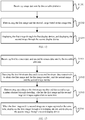
FIG. 1 illustrates a flowchart of an image transmission method according to an embodiment of the present disclosure. As shown inFIG. 1 , the method in one embodiment may include: - In S101, acquiring a first image captured by a first photographing device mounted on a movable platform, and a second image captured by a second photographing device mounted on the movable platform. The first image and the second image are captured at the same time.
- The image transmission method described in one embodiment is applicable to a movable platform and a corresponding monitoring device thereof, and the movable platform includes at least one of the following: an unmanned aerial vehicle (UAV), a movable robot, a model airplane, a remote-control vehicle, or a remote-control boat.
- In one embodiment, a UAV is taken as an example to illustrate the image transmission process between the UAV and a ground monitoring device. As shown in
FIG. 2 , aUAV 20 is equipped with a first photographingdevice 21 and a second photographingdevice 22. The first photographingdevice 21 may be, for example, a camera, and the second photographingdevice 22 may be, for example, another camera. Aprocessor 23 is communicatively connected to the first photographingdevice 21 and the second photographingdevice 22, and theprocessor 23 may be able to control the first photographingdevice 21 and the second photographingdevice 22 to take image information at the same time. - The method of this embodiment may be executed by a processor in a movable platform. The processor may be other general purpose or dedicated processors, and the processor may have image processing functions.
- For example, the
processor 23 may be able to acquire the image information captured by the first photographingdevice 21 and the second photographingdevice 22 at the same time. In the embodiment, the image information captured by the first photographingdevice 21 may be denoted as a first image, and the image information captured by the second photographingdevice 22 may be denoted as a second image. - In other embodiments, the
processor 23 may further be able to control the photographing parameters of the first photographingdevice 21 and the second photographingdevice 22, such that the photographing parameters for the first image captured by the first photographingdevice 21 and the second image captured by the second photographingdevice 22 are the same. The photographing parameters may include at least one of the following: an exposure time, a shutter speed, or an aperture size. - In S102, performing image processing on the first image and the second image to obtain image-processed image data.
- After acquiring the first image captured by the first photographing
device 21 and the second image captured by the second photographingdevice 22 at the same time, theprocessor 23 may perform image processing on the first image and the second image to obtain image-processed image data. - For example, an implementation method for performing image processing on the first image and the second image to obtain image-processed image data includes: combining the first image and the second image into a target image; and encoding the target image to obtain encoded image data. As shown in
FIG. 3 , 31 denotes the first image captured by the first photographingdevice device 22, and theprocessor 23 may first combine thefirst image 31 and thesecond image 32 into atarget image 33. Further, thetarget image 33 may be encoded to obtain encodedimage data 34. - For example, combining the first image and the second image into the target image may include the following possible implementation methods.
- A possible implementation method includes: splicing the first image and the second image left and right to obtain the target image. As shown in
FIG. 4 , thefirst image 31 may be spliced to the left side of thesecond image 32 to obtain the splicedtarget image 33. Alternatively, as shown inFIG. 5 , thefirst image 31 may be spliced to the right side of thesecond image 32 to obtain the splicedtarget image 33. - Another possible implementation method includes: splicing the first image and the second image up and down to obtain the target image. As shown in
FIG. 6 , thefirst image 31 may be spliced on the upper side of thesecond image 32 to obtain the splicedtarget image 33. Alternatively, as shown inFIG. 7 , thefirst image 31 may be spliced on the lower side of thesecond image 32 to obtain the splicedtarget image 33. - The splicing methods shown in
FIG. 4 to FIG. 7 are only illustrative and not specifically limited. In other embodiments, other image synthesis methods may be included. - In S103, sending the image-processed image data to a monitoring device, so that the monitoring device determines the first image and the second image based on the image data, and displays the first image through a first display device and displays the second image through a second display device.
- As shown in
FIG. 2 orFIG. 3 , theprocessor 23 may transmit theimage data 34 processed from thefirst image 31 and thesecond image 32 to aground monitoring device 25 through acommunication system 24 of theUAV 20. Themonitoring device 25 may receive the image data sent by theUAV 20 through anantenna 114. Themonitoring device 25 may include at least one of the following: a remote controller, a user terminal device, or headwear glasses. Alternatively, themonitoring device 25 can also be a wearable device. - As shown in
FIG. 8 , after themonitoring device 25 receives the encodedimage data 34, theprocessor 26 of themonitoring device 25 may first decode the encodedimage data 34 to obtain thetarget image 33, further decompose thetarget image 33 to obtain thefirst image 31 and thesecond image 32, and may display thefirst image 31 through afirst display device 27 and display thesecond image 32 through asecond display device 28, or display thesecond image 32 through thefirst display device 27 and display thefirst image 31 through thesecond display device 28. Thefirst display device 27 may be, for example, a display screen, and thesecond display device 28 may be, for example, another display screen. - In one embodiment, the
first display device 27 and thesecond display device 28 may be disposed on themonitoring device 25. Alternatively, thefirst display device 27 and thesecond display device 28 may be external devices of themonitoring device 25, and thefirst display device 27 and thesecond display device 28 may be communicatively connected to themonitoring device 25, respectively, as shown inFIG. 9 . - According to various embodiments, two images captured at the same time respectively by two photographing devices mounted on a movable platform are acquired, image processing is performed on the two images to obtain image data, the image data is sent to a monitoring device, and the monitoring device restores the two images based on the image data and displays one image through each of two display devices, such that the picture on a monitor screen observed by the user through the two display devices is more in line with the visual characteristics of the human eye, and thus lack of parallax information or depth information in the picture on the monitor screen can be avoided. The user may be able to accurately determine the farness and/or nearness of objects in the picture on the monitor screen, and thus the accuracy of remote monitoring of the movable platform may be improved.
- The embodiments of the present disclosure provide an image transmission method.
FIG. 10 illustrates a flowchart of an image transmission method according to another embodiment of the present disclosure. As shown inFIG. 10 , based on the embodiment shown inFIG. 1 , another implementation method for performing image processing on the first image and the second image to obtain image-processed image data inS 102 may include the following steps. - In S 1021, numbering the first image and the second image, respectively.
- For example, the
processor 23 may number the first image captured by the first photographingdevice 21 and the second image captured by the second photographingdevice 22, respectively. In one example, the first image number may be 001, and the second image number may be 002. - In S1022, encoding the first image and the first image number to obtain encoded first bit-stream data.
- As shown in
FIG. 11 , theprocessor 23 may encode the first image and the first image number to obtain encoded first bit-stream data 110. - In S1023, encoding the second image and the second image number to obtain encoded second bit-stream data.
- As shown in
FIG. 11 , theprocessor 23 may encode the second image and the second image number to obtain encoded second bit-stream data 111. - Correspondingly, S103 of sending the image-processed image data to the monitoring device may include S1031 shown in
FIG. 10 : sending the encoded first bit-stream data and the encoded second bit-stream data to the monitoring device. - For example, the
processor 23 may send the encoded first bit-stream data 110 and the encoded second bit-stream data 111 to theground monitoring device 25 through thecommunication system 24 of theUAV 20. In one embodiment, thecommunication system 24 may send the encoded first bit-stream data 110 and the encoded second bit-stream data 111 to themonitoring device 25 in a predetermined order, e.g. a coding order. - According to various embodiments, the encoded first bit-stream data is obtained after encoding the first image and the first image number, and the encoded second bit-stream data is obtained after encoding the second image and the second image number. Compared with combining the first image and the second image, and encoding the combined image, the disclosed image transmission method reduces the coding rate, and in the meantime, reduces the requirement on the transmission bandwidth.
- The embodiments of the present disclosure provide an image transmission method. Based on the embodiments described above, the method may further include: controlling the photographing parameters of the first photographing device and the second photographing device. As shown in
FIG. 2 , theprocessor 23 of theUAV 20 may also be able to control the photographing parameters of the first photographingdevice 21 and the second photographingdevice 22. The photographing parameters may include at least one of the following: an exposure time, a shutter speed, or an aperture size. - In one embodiment, the first image and the second image may be captured at the same time, and the photographing parameters of the first image and the second image may be the same.
- In addition, the relative position of the first photographing device and the second photographing device maybe determined by simulating the relative position of the human eyes. The first photographing device and the second photographing device may be disposed at a same level on the movable platform. For example, the first photographing
device 21 and the second photographingdevice 22 may be disposed on theUAV 20 at a same level. - Furthermore, the first photographing device and the second photographing device may be used to acquire a three-dimensional image.
- The method may also include sending the three-dimensional image to a monitoring device so that the monitoring device displays the three-dimensional image through the first display device and the second display device. For example, the
processor 23 may also be able to send the three-dimensional image acquired by the first photographingdevice 21 and the second photographingdevice 22 to theground monitoring device 25 through thecommunication system 24 of theUAV 20. After themonitoring device 25 receives the three-dimensional image, as shown inFIG. 8 orFIG. 9 , the three-dimensional image may be displayed through thefirst display device 27 and thesecond display device 28. - According to various embodiments, a three-dimensional image may be acquired by the first photographing device and the second photographing device, and the three-dimensional image may be sent to a ground monitoring device. The three-dimensional image may be able to provide a more realistic and natural picture on the monitor screen to the user, so that the user may be able to accurately determine the farness and/or nearness of objects in the picture on the monitor screen, and thus the accuracy of remote monitoring of the movable platform may be improved.
- The embodiments of the present disclosure provide an image transmission method.
FIG. 12 illustrates a schematic flowchart of an image transmission method according to another embodiment of the present disclosure. In one embodiment, the method may be executed by a monitoring device. As shown inFIG. 12 , the method in this embodiment may include: - In S1201, receiving image data sent by the movable platform.
- The image data may be obtained after the movable platform performs image processing on a first image captured by a first photographing device and a second image captured by a second photographing device. The first photographing device and the second photographing device are mounted on the movable platform, and the first image and the second image are captured at the same time.
- As shown in
FIG. 2 , theUAV 20 may be equipped with a first photographingdevice 21 and a second photographingdevice 22. The first photographingdevice 21 may be, for example, a camera, and the second photographingdevice 22 may be, for example, another camera. Theprocessor 23 of theUAV 20 may be able to acquire a first image captured by the first photographingdevice 21 and a second image captured by the second photographingdevice 22 at the same time. Further, theprocessor 23 may perform image processing on the first image and the second image to obtain image-processed image data. The image data may be sent to aground monitoring device 25 through thecommunication system 24 of theUAV 20, and themonitoring device 25 may receive the image data sent by theUAV 20 through theantenna 114. - In S1202, determining the first image and the second image based on the image data.
- In one embodiment, the image data is encoded image data obtained after the movable platform combines the first image and the second image to a target image and encodes the target image. In this case, determining the first image and the second image based on the image data may include: decoding the encoded image data to obtain the target image; and decomposing the target image into the first image and the second image.
- As shown in
FIG. 3 , 31 denotes a first image captured by a first photographingdevice device 22, and theprocessor 23 may first combine thefirst image 31 and thesecond image 32 into atarget image 33. Further, thetarget image 33 may be encoded to obtain encodedimage data 34. After themonitoring device 25 receives the image data sent by theUAV 20 through theantenna 114, theprocessor 26 of themonitoring device 25 may first decode theimage data 34 to obtain thetarget image 33, and further decompose thetarget image 33 into thefirst image 31 and thesecond image 32. - Depending on how the target image is formed, different methods may be used to decompose the target image into the first image and the second image.
- An implementation method for forming the target image includes that: the target image may be obtained after the movable platform splices the first image and the second image left and right. Correspondingly, the decomposing the target image into the first image and the second image may include: decomposing the target image left and right to obtain the first image and the second image.
- As shown in
FIG. 4 , thefirst image 31 may be spliced to the left side of thesecond image 32 to obtain the splicedtarget image 33. Alternatively, as shown inFIG. 5 , thefirst image 31 may be spliced to the right side of thesecond image 32 to obtain the splicedtarget image 33. In this case, theprocessor 26 of themonitoring device 25 may decompose thetarget image 33 left and right to obtain thefirst image 31 and thesecond image 32. - Another implementation method for forming the target image includes that: the target image may be obtained after the movable platform splices the first image and the second image up and down. Correspondingly, the decomposing the target image into the first image and the second image may include: decomposing the target image up and down to obtain the first image and the second image.
- As shown in
FIG. 6 , thefirst image 31 may be spliced to the upper side of thesecond image 32 to obtain the splicedtarget image 33. Alternatively, as shown inFIG. 5 , thefirst image 31 may be spliced to the lower side of thesecond image 32 to obtain the splicedtarget image 33. In this case, theprocessor 26 of themonitoring device 25 may decompose thetarget image 33 left and right to obtain thefirst image 31 and thesecond image 32. - In S1203, displaying the first image through the first display device, and displaying the second image through the second display device.
- As shown in
FIG. 8 orFIG. 9 , theprocessor 26 of themonitoring device 25 may display thefirst image 31 through thefirst display device 27 and display thesecond image 32 through thesecond display device 28, or display thesecond image 32 through thefirst display device 27 and display thefirst image 31 through thesecond display device 28. Thefirst display device 27 may be, for example, a display screen, and thesecond display device 28 may be, for example, another display screen. - According to various embodiments, two images captured at the same time respectively by two photographing devices mounted on a movable platform are acquired, image processing is performed on the two images to obtain image data, the image data is sent to a monitoring device, and the monitoring device restores the two images based on the image data and displays one image through each of two display devices, such that the picture on the monitor screen observed by the user through the two display devices is more in line with the visual characteristics of the human eye, and thus lack of parallax information or depth information in the picture on the monitor screen can be avoided. The user may be able to accurately determine the farness and/or nearness of objects in the picture on the monitor screen, and thus the accuracy of remote monitoring of the movable platform may be improved.
- The embodiments of the present disclosure provide an image transmission method.
FIG. 13 illustrates a flowchart of an image transmission method according to another embodiment of the present disclosure. The method of this embodiment may be executed by a monitoring device. As shown inFIG. 13 , in one embodiment, the method may include: - In S1301, receiving first bit-stream data and second bit-stream data sent by the movable platform.
- The first bit-stream data may be obtained after the movable platform encodes the first image and the first image number, and the second bit-stream data may be obtained after the movable platform encodes the second image and the second image number.
- As shown in
FIG. 11 , theprocessor 23 may number the first image captured by thefirst imaging device 21 and the second image captured by thesecond imaging device 22, respectively. For example, the first image number may be 001, and the second image number may be 002. Theprocessor 23 may encode the first image and the first image number to obtain the encoded first bit-stream data 110. Theprocessor 23 may encode the second image and the second image number to obtain the encoded second bit-stream data 111. Theprocessor 23 may send the encoded first bit-stream data 110 and the encoded second bit-stream data 111 to theground monitoring device 25 through thecommunication system 24 of theUAV 20. Themonitoring device 25 may receive the encoded first bit-stream data 110 and the encoded second bit-stream data 111 sent by thecommunication system 24 through theantenna 114. - In S1302, decoding the first bit-stream data and the second bit-stream data respectively to obtain the first image and the first image number, and the second image and the second image number.
- Further, the
processor 26 of themonitoring device 25 may decode the first bit-stream data 110 and the second bit-stream data 111, respectively to obtain the first image and thefirst image number 001, and the second image and thesecond image number 002. - In S1303, determining, according to the first image number and the second image number obtained through decoding, whether the first image and the second image are images captured at the same time.
- The
processor 26 of themonitoring device 25 may determine, according to thefirst image number 001 and thesecond image number 002, whether the first image and the second image are images captured at the same time. - For example, the determining, according to the first image number and the second image number obtained through decoding, whether the first image and the second image are images captured at the same time, may include: when the first image number and the second image number obtained through decoding match each other, determining that the first image and the second image are images captured at the same time.
- For example, the
processor 23 of theUAV 20 respectively numbers the first image and the second image captured at the same time according to a preset numbering rule, and theprocessor 26 of themonitoring device 25 may be able to determine, according to the preset numbering rule, whether thefirst image number 001 and thesecond image number 002 conform to the preset numbering rule. For example, in the preset numbering rule: 001 and 002 are a pair of numbers, 003 and 004 are a pair of numbers, 1 and 10001 are a pair of numbers, 2 and 10002 are a pair of numbers, etc. This is merely a schematic description and is not limited to any specific number. Then, after theprocessor 26 of themonitoring device 25 decodes the first bit-stream data 110 and the second bit-stream data 111, respectively to obtain the first image and thefirst image number 001, and the second image and thesecond image number - In S1304, when the first image and the second image are images captured at the same time, displaying the first image through a first display device, and displaying the second image through a second display device.
- After the
processor 26 of themonitoring device 25 determines that the first image and the second image are a pair of images captured at the same time according to S1303 described above, as shown inFIG. 8 orFIG. 9 , theprocessor 26 of themonitoring device 25 may display thefirst image 31 through thefirst display device 27 and display thesecond image 32 through thesecond display device 28, or display thesecond image 32 through thefirst display device 27 and display thefirst image 31 through thesecond display device 28. Thefirst display device 27 may be, for example, a display screen, and thesecond display device 28 may be, for example, another display screen. - According to various embodiments, the encoded first bit-stream data is obtained after encoding the first image and the first image number, and the encoded second bit-stream data is obtained after encoding the second image and the second image number. Compared with combining the first image and the second image, and encoding the combined image, the disclosed image transmission method reduces the coding rate, and in the meantime, reduces the requirement on the transmission bandwidth.
- The embodiments of the present disclosure provide an image transmission method.
FIG. 14 illustrates a flowchart of an image transmission method according to another embodiment of the present disclosure. The method of this embodiment may be executed by a monitoring device. As shown inFIG. 14 , the method in this embodiment may include: - In S1401, receiving first bit-stream data and second bit-stream data sent by the movable platform.
- The first bit-stream data may be obtained after the movable platform encodes the first image and the first image number, and the second bit-stream data may be obtained after the movable platform encodes the second image and the second image number.
- The specific principle and implementation method of S1401 are similar to S1301, and the details are not described herein again.
- In S1402, decoding the first bit-stream data to obtain the first image and the first image number.
- After the
monitoring device 25 receives the encoded first bit-stream data 110 and the encoded second bit-stream data 111 sent by thecommunication system 24 through theantenna 114, theprocessor 26 of themonitoring device 25 may decode the first bit-stream data 110 to obtain the first image and thefirst image number 001. - In S1403, caching the first image and the first image number.
- In one embodiment, the
monitoring device 25 may further include a buffer. After theprocessor 26 decodes the first bit-stream data 110 to obtain the first image and thefirst image number 001, the first image and thefirst image number 001 may be cached in the buffer first. - In S1404, decoding the second bit-stream data to obtain the second image and the second image number.
- Further, the
processor 26 of themonitoring device 25 may decode the second bit-stream data 111 to obtain the second image and thesecond image number 002. - In S1405, determining, according to the second image number and the first image number in the buffer, whether the first image and the second image are images captured at the same time.
- The
processor 26 may determine, according to thesecond image number 002 and thefirst image number 001 in the buffer, whether the first image and the second image are images captured at the same time. - In one embodiment, when the second image number matches the first image number in the buffer, it may be determined that the first image and the second image are images captured at the same time. For example, in the preset numbering rule, it may be prescribed that 001 and 002 are a pair of numbers, 003 and 004 are a pair of numbers, etc.; then, the
second image number 002 matching thefirst image number 001 in the buffer may indicate that the first image and the second image are a pair of images captured at the same time. - In S1406, when the first image and the second image are images captured at the same time, displaying the first image through the first display device, and displaying the second image through the second display device.
- After the
processor 26 of themonitoring device 25 determines that the first image and the second image are a pair of images captured at the same time according to S1303 described above, as shown inFIG. 8 orFIG. 9 , theprocessor 26 of themonitoring device 25 may display thefirst image 31 through thefirst display device 27 and display thesecond image 32 through thesecond display device 28, or display thesecond image 32 through thefirst display device 27 and display thefirst image 31 through thesecond display device 28. Thefirst display device 27 may be, for example, a display screen, and thesecond display device 28 may be, for example, another display screen. - In addition, in one embodiment, the first photographing device and the second photographing device may be used to acquire a three-dimensional image. The method may further include receiving the three-dimensional image sent by the movable platform; and displaying the three-dimensional image through the first display device and the second display device.
- In one embodiment, the first photographing
device 21 and the second photographingdevice 22 may be disposed at a same level on theUAV 20. The relative position of the first photographingdevice 21 and the second photographingdevice 22 may be determined by simulating the relative position of the human eyes. The first photographingdevice 21 and the second photographingdevice 22 may also be used to acquire a three-dimensional image. In this case, theprocessor 23 may also be able to send the three-dimensional image acquired by the first photographingdevice 21 and the second photographingdevice 22 to theground monitoring device 25 by thecommunication system 24 of theUAV 20. After themonitoring device 25 receives the three-dimensional image, as shown inFIG. 8 orFIG. 9 , the three-dimensional image may be displayed through thefirst display device 27 and thesecond display device 28. - According to various embodiments, a three-dimensional image may be acquired by the first photographing device and the second photographing device, and the three-dimensional image may be sent to a ground monitoring device. The three-dimensional image may be able to provide a more realistic and natural picture on the monitor screen for the user, so that the user may be able to accurately determine the farness and/or nearness of objects in the picture on the monitor screen, and thus the accuracy of remote monitoring of the movable platform may be improved.
- The embodiments of the present disclosure provide an image transmission device.
FIG. 15 illustrates a structural diagram of an image transmission device according to an embodiment of the present disclosure. As shown inFIG. 15 , theimage transmission device 150 may include: afirst communication interface 151 and afirst processor 152. Thefirst processor 152 may be configured to acquire a first image captured by a first photographing device mounted on a movable platform, and a second image captured by a second photographing device mounted on the movable platform. The first image and the second image may be captured at the same time. Image processing may be performed on the first image and the second image to obtain image-processed image data. Thefirst communication interface 151 may be configured to send the image-processed image data to the monitoring device, so that the monitoring device determines the first image and the second image based on the image data, and displays the first image through a first display device and displays the second image through a second display device. - In one embodiment, when performing image processing on the first image and the second image to obtain the image-processed image data, the
first processor 152 may be configured to: combine the first image and the second image into a target image; and encode the target image to obtain encoded image data. - The
first processor 152 combining the first image and the second image into the target image may include the following possible cases. - One possible case includes that the first image and the second image may be spliced left and right to obtain the target image.
- Another possible case includes that the first image and the second image may be spliced up and down to obtain the target image.
- The specific principles and implementation methods of the image transmission device provided by the embodiments of the present disclosure are similar to the embodiment shown in
FIG. 1 and the details are not described herein again. - According to various embodiments, two images captured at the same time respectively by two photographing devices mounted on a movable platform are acquired, image processing is performed on the two images to obtain image data, the image data is sent to a monitoring device, and the monitoring device restores the two images based on the image data and displays one image through each of two display devices, such that the picture on the monitor screen observed by the user through the two display devices is more in line with the visual characteristics of the human eye, and thus lack of parallax information or depth information in the picture on the monitor screen can be avoided. The user may be able to accurately determine the farness and/or nearness of objects in the picture on the monitor screen, and thus the accuracy of remote monitoring of the movable platform may be improved.
- The embodiments of the present disclosure provide an image transmission device. On the basis of the technical solution provided by the embodiment shown in
FIG. 15 , thefirst processor 152 performing image processing on the first image and the second image to obtain the image-processed image data may include: numbering the first image and the second image, respectively; encoding the first image and the first image number to obtain encoded first bit-stream data; and encoding the second image and the second image number to obtain encoded second bit-stream data. - Accordingly, when sending the image-processed image data to the monitoring device, the
first communication interface 151 may be configured to send the encoded first bit-stream data and the encoded second bit-stream data to the monitoring device. - In one embodiment, the
first processor 152 may be further configured to control the photographing parameters of the first photographing device and the second photographing device. The photographing parameters may include at least one of the following: an exposure time, a shutter speed, or an aperture size. - In one embodiment, the photographing parameters for the first image and the second image may be the same. The relative position of the first photographing device and the second photographing device maybe determined by simulating the relative position of the human eyes. The first photographing device and the second photographing device may be disposed at a same level on the movable platform. The first photographing device and the second photographing device may be used to capture a three-dimensional image.
- The
first communication interface 151 may be further configured to send the three-dimensional image to the monitoring device, so that the monitoring device displays the three-dimensional image through a first display device and a second display device. - In one embodiment, the
first processor 152 may include at least one of the following: a complex programmable logic device (CPLD), a field programmable gate array (FPGA), or a bridge chip. - The specific principles and implementation methods of the image transmission device provided by the embodiment of the present disclosure are similar to the embodiment shown in
FIG. 10 , and the details are not described herein again. - According to various embodiments, the encoded first bit-stream data is obtained after encoding the first image and the first image number, and the encoded second bit-stream data is obtained after encoding the second image and the second image number. Compared with combining the first image and the second image, and encoding the combined image, the disclosed image transmission method reduces the coding rate, and in the meantime, reduces the requirement on the transmission bandwidth. In addition, a three-dimensional image may be acquired by the first photographing device and the second photographing device, and the three-dimensional image may be sent to a ground monitoring device. The three-dimensional image may be able to provide a more realistic and natural picture on the monitor screen for the user, so that the user may be able to accurately determine the farness and/or nearness of objects in the picture on the monitor screen, and thus the accuracy of remote monitoring of the movable platform may be improved
- The embodiments of the present disclosure provides a movable platform. The movable platform may include at least one of the following: a UAV, a movable robot, a model airplane, a remote-control vehicle, or a remote-control boat. In one embodiment, the movable platform is, for example, a UAV.
FIG. 16 illustrates a structural diagram of a UAV according to an embodiment of the present disclosure. As shown inFIG. 16 , theUAV 100 may include: a fuselage, a propulsion system, and aflight controller 118. The propulsion system may include at least one of the following: amotor 107, apropeller 106, or anelectronic speed control 117. The propulsion system may be mounted to the fuselage for providing flight propulsion; and theflight controller 118 may be communicatively connected to the propulsion system for controlling the UAV to fly. - In addition, as shown in
FIG. 16 , theUAV 100 may further include: a first photographingdevice 21, a second photographingdevice 22, and animage transmission device 150. The specific principles and implementation methods of theimage transmission device 150 are similar to the embodiments described above, and the details are not described herein again. - According to various embodiments, two images captured at the same time respectively by two photographing devices mounted on a movable platform are acquired, image processing is performed on the two images to obtain image data, the image data is sent to a monitoring device, and the monitoring device restores the two images based on the image data and displays one image through each of two display devices, such that the picture on the monitor screen observed by the user through the two display devices is more in line with the visual characteristics of the human eye, and thus lack of parallax information or depth information in the picture on the monitor screen can be avoided. The user may be able to accurately determine the farness and/or nearness of objects in the picture on the monitor screen, and thus the accuracy of remote monitoring of the movable platform may be improved.
- The embodiments of the present disclosure provides a monitoring device.
FIG. 17 illustrates a structural diagram of a monitoring device according to an embodiment of the present disclosure. Referring toFIG. 17 , themonitoring device 170 may include: asecond communication interface 171, asecond processor 172, afirst display device 173, and asecond display device 174. Thesecond communication interface 171 may be configured to: receive the image data sent by the movable platform. The image data may be obtained after the movable platform performs image processing on a first image captured by a first photographing device and a second image captured by a second photographing device. The first photographing device and the second photographing device may be mounted on the movable platform, and the first image and the second image may be captured at the same time. Thesecond processor 172 may be configured to: determine the first image and the second image based on the image data; and display the first image through thefirst display device 173, and display the second image through thesecond display device 174. - In one embodiment, the image data may be encoded image data obtained after the movable platform combines the first image and the second image into a target image and encodes the target image. Correspondingly, when determining the first image and the second image based on the image data, the
second processor 172 may be configured to decode the encoded image data to obtain the target image; and decompose the target image into the first image and the second image. - For example, the target image may have the following formation methods.
- One possible formation method includes that the target image may be obtained after the movable platform splices the first image and the second image left and right. In this case, when decomposing the target image to obtain the first image and the second image, the
second processor 172 may be configured to decompose the target image left and right to obtain the first image and the second image. - Another possible formation method includes that the target image may be obtained after the movable platform splices the first image and the second image up and down. In this case, when decomposing the target image to obtain the first image and the second image, the
second processor 172 may be configured to decompose the target image up and down to obtain the first image and the second image. - In other embodiments, the
first display device 173 and thesecond display device 174 may be external devices of themonitoring device 170. - The specific principles and implementation methods of the monitoring device provided by the embodiment of the present disclosure are similar to the embodiment shown in
FIG. 12 , and the details are not described herein again. - According to various embodiments, two images captured at the same time respectively by two photographing devices mounted on a movable platform are acquired, image processing is performed on the two images to obtain image data, the image data is sent to a monitoring device, and the monitoring device restores the two images based on the image data and displays one image through each of two display devices, such that the picture on the monitor screen observed by the user through the two display devices is more in line with the visual characteristics of the human eye, and thus lack of parallax information or depth information in the picture on the monitor screen can be avoided. The user may be able to accurately determine the farness and/or nearness of objects in the picture on the monitor screen, and thus the accuracy of remote monitoring of the movable platform may be improved.
- The embodiments of the present disclosure provide a monitoring device. On the basis of the technical solution provided by the embodiment shown in
FIG. 17 , when receiving the image data sent by the movable platform, thesecond communication interface 171 may be specifically configured to: receive first bit-stream data and second data sent by the movable platform. The first bit-stream data may be obtained after the movable platform encodes the first image and the first image number, and the second bit-stream data may be obtained after the movable platform encodes the second image and the second image number. - When determining the first image and the second image based on the image data, the
second processor 172 may be configured to decode the first bit-stream data and the second bit-stream data respectively to obtain the first image and the first image number, and the second image and the second image number. - After decoding the first bit-stream data and the second bit-stream data respectively to obtain the first image and the first image number, and the second image and the second image number, the
second processor 172 may be further configured to determine, according to the first image number and the second image number obtained through decoding, whether the first image and the second image are images captured at the same time. - In one embodiment, when determining, according to the first image number and the second image number obtained through decoding, whether the first image and the second image are images captured at the same time, the
second processor 172 may be configured to determine whether the first image number and the second image number obtained through decoding match each other; and when the first image number and the second image number obtained through decoding match each other, determine that the first image and the second image are images captured at the same time. - The specific principles and implementation methods of the monitoring device provided by the embodiment of the present disclosure are similar to the embodiment shown in
FIG. 13 , and the details are not described herein again. - According to various embodiments, the encoded first bit-stream data is obtained after encoding the first image and the first image number, and the encoded second bit-stream data is obtained after encoding the second image and the second image number. Compared with combining the first image and the second image, and encoding the combined image, the disclosed image transmission method reduces the coding rate, and in the meantime, reduces the requirement on the transmission bandwidth.
- The embodiments of the present disclosure provide a monitoring device. The monitoring device may include at least one of the following: a remote controller, a user terminal device, or headwear glasses.
FIG. 18 illustrates a structural diagram of a monitoring device according to another embodiment of the present disclosure. Referring toFIG. 18 , on the basis of the technical solution provided by the embodiment shown inFIG. 17 , themonitoring device 170 may further include: abuffer 175. When decoding the first bit-stream data and the second bit-stream data respectively to obtain the first image and the first image number, and the second image and the second image number, thesecond processor 172 may be configured to decode the first bit-stream data to obtain the first image and the first image number; cache the first image and the first image number into thebuffer 175; and decode the second bit-stream data to obtain the second image and the second image number. - After decoding the second bit-stream data to obtain the second image and the second image number, the
second processor 172 may be further configured to determine, according to the second image number and the first image number in the buffer, whether the first image and the second image are images captured at the same time. - For example, when determining, according to the second image number and the first image number in the buffer, whether the first image and the second image are images captured at the same time, the
second processor 172 may be configured to determine whether the second image number and the first image number in the buffer match each other; and when the second image number and the first image number in the buffer match each other, determine that the first image and the second image are images captured at the same time. - The first photographing device and the second photographing device may be used to acquire a three-dimensional image. In one embodiment, the
second communication interface 171 may be further configured to: receive the three-dimensional image sent by the movable platform; and display the three-dimensional image through a first display device and a second display device. - In one embodiment, the
second processor 172 may include at least one of the following: a CPLD, an FPGA, or a bridge chip. - The specific principles and implementation methods of the monitoring device provided by the embodiment of the present disclosure are similar to the embodiment shown in
FIG. 14 , and the details are not described herein again. - According to various embodiments, a three-dimensional image may be acquired by the first photographing device and the second photographing device, and the three-dimensional image may be sent to a ground monitoring device. The three-dimensional image may be able to provide a more realistic and natural picture on the monitor screen for the user, so that the user may be able to accurately determine the farness and/or nearness of objects in the picture on the monitor screen, and thus the accuracy of remote monitoring of the movable platform may be improved.
- The embodiments of the present disclosure provide an image transmission system. As shown in
FIG. 2 ,FIG. 8 , orFIG. 9 , the image transmission system may include a movable platform, such as aUAV 20 and amonitoring device 25. - In the various embodiments provided by the present application, it should be understood that the disclosed systems, devices, and methods may be implemented in other manners. For example, the device embodiments described above are merely illustrative. For instance, in various embodiments of the present disclosure, the units are divided or defined merely according to the logical functions of the units, and in actual applications, the units may be divided or defined in another manner. For example, multiple units or components may be combined or integrated into another system, or some features can be ignored or not executed. In addition, the mutual coupling or direct coupling or communication connection shown or discussed may be an indirect coupling or communication connection through some interface, device or unit, and may be in an electrical, mechanical, or other form.
- The units described as separate components may or may not be physically separated, and the components displayed as a unit may or may not be physical in a unit, that is, they may be located in one place, or may be distributed to multiple network units. Some or all of the units may be selected according to actual needs to achieve the purpose of the solution of the embodiment.
- In addition, each functional unit in each embodiment of the present application may be integrated into one processing unit, or each unit may exist physically separately, or two or more units may be integrated into one unit.
- The above-described integrated unit implemented in the form of a software functional unit can be stored in a computer readable storage medium. The above software functional unit is stored in a storage medium and includes instructions for making a computer device (which may be a personal computer, a server, or a network device, etc.) or a processor perform part of the steps of the methods according to the various embodiments of the present disclosure. The storage medium described above may include various media that can store program codes, such as a U disk, a movable hard disk, a read-only memory (ROM), a random access memory (RAM), a magnetic disk, an optical disk, etc.
- Those skilled in the art should clearly understand that for the convenience and simplicity of the description, only the division of the above functional modules examples is illustrated. In practical applications, the above function assignment can be completed by different functional modules according to needs, that is, the internal structure of the device may be divided into different functional modules to implement all or part of the functions described above. For the specific operation process of the device described above, reference may be made to the corresponding process in the aforementioned method embodiments, and details are not described herein again.
- Finally, it should be noted that the above embodiments are merely illustrative of, but not intended to limit, the technical solutions of the present invention; although the present disclosure has been described in detail with reference to the above embodiments, those skilled in the art should understand that the technical solutions described in the above embodiments may be modified, or part or all of the technical features may be equivalently replaced; and the modifications or substitutions do not depart from the scope of the technical solutions of the embodiments of the present disclosure.
| 20 - unmanned aerial vehicle | 21 - first photographing device | 22 - second photographing device |
| 23 - processor | 24 - communication system | 25 - monitoring device |
| 26 - processor | 27 - first display device | 28 - second display device |
| 114 - antenna | 31 - first image | 32 - second image |
| 33 - target image | 34 - image data | 110 - first bit-stream data |
| 111 - second bit-stream data | 150 - image transmission device | |
| 151 - first communication interface | 152 - first processor | 100 - unmanned aerial vehicle |
| 106 - propeller | ||
| 107 - motor | 117 - electronic speed control | 118 - flight controller |
| 170 - monitoring device | 171 - second communication interface | 172 - second processor |
| 173 - first display device | 174 - second display device | 175 - buffer |
Claims (66)
- An image transmission method, comprising:acquiring a first image captured by a first photographing device, and a second image captured by a second photographing device mounted on a movable platform, wherein the first image and the second image are captured at a same time;performing image processing on the first image and the second image to obtain image-processed image data; andsending the image-processed image data to a monitoring device, so that the monitoring device determines the first image and the second image based on the image data, and displays the first image through a first display device and displays the second image through a second display device.
- The method according to claim 1, wherein the performing of the image processing on the first image and the second image to obtain the image-processed image data includes:combining the first image and the second image into a target image; andencoding the target image to obtain encoded image data.
- The method according to claim 2, wherein the combining of the first image and the second image into the target image includes:
splicing the first image and the second image left and right to obtain the target image. - The method according to claim 2, wherein the combining of the first image and the second image into the target image includes:
splicing the first image and the second image up and down to obtain the target image. - The method according to claim 1, wherein the performing of the image processing on the first image and the second image to obtain the image-processed image data includes:numbering the first image and the second image, respectively;encoding the first image and a first image number to obtain encoded first bit-stream data; andencoding the second image and a second image number to obtain encoded second bit-stream data.
- The method according to claim 5, wherein the sending of the image-processed image data to the monitoring device includes:
sending the encoded first bit-stream data and the encoded second bit-stream data to the monitoring device. - The method according to claim 1, further including:
controlling photographing parameters of the first photographing device and the second photographing device. - The method according to claim 7, wherein the photographing parameters includes at least one of:
an exposure time, a shutter speed, or an aperture size. - The method according to claim 8, wherein:
the photographing parameters of the first image and the second image are same. - The method according to any one of claims 1-9, wherein:
a relative position of the first photographing device and the second photographing device is determined by simulating a relative position of human eyes. - The method according to claim 10, wherein:
the first photographing device and the second photographing are disposed on the movable platform at a same level. - The method according to claim 11, wherein:
the first photographing device and the second photographing device are used to acquire a three-dimensional image. - The method according to claim 12, further including:
sending the three-dimensional image to the monitoring device, so that the monitoring device displays the three-dimensional image through the first display device and the second display device. - The method according to claim 1, wherein the movable platform includes at least one of:
an unmanned aerial vehicle, a movable robot, a model airplane, a remote-control vehicle, or a remote-control boat. - The method according to claim 1, wherein the monitoring device includes at least one of:
a remote controller, a user terminal device, or headwear glasses. - An image transmission method, comprising:receiving image data sent by a movable platform, wherein the image data is obtained after the movable platform performs image processing on a first image captured by a first photographing device and a second image captured by a second photographing device, wherein the first photographing device and the second photographing device are mounted on the movable platform, and the first image and the second image are captured at a same time;determining the first image and the second image based on the image data; anddisplaying the first image through a first display device, and displaying the second image through a second display device.
- The method according to claim 16, wherein:
the image data is encoded image data obtained after the movable platform combines the first image and the second image into a target image and encodes the target image. - The method according to claim 17, wherein the determining of the first image and the second image based on the image data includes:decoding the encoded image data to obtain the target image; anddecomposing the target image into the first image and the second image.
- The method according to claim 18, wherein:
the target image is obtained after the movable platform splices the first image and the second image left and right. - The method according to claim 19, wherein the decomposing of the target image into the first image and the second image includes:
decomposing the target image left and right to obtain the first image and the second image. - The method according to claim 18, wherein:
the target image is obtained after the movable platform splices the first image and the second image up and down. - The method according to claim 19, wherein the decomposing of the target image into the first image and the second image includes:
decomposing the target image up and down to obtain the first image and the second image. - The method according to claim 16, wherein the receiving of the image data sent by the movable platform includes:
receiving first bit-stream data and second bit-stream data sent by the movable platform, wherein the first bit-stream data is obtained after the movable platform encodes the first image and a first image number, and the second bit-stream data is obtained after the movable platform encodes the second image and a second image number. - The method according to claim 23, wherein the determining of the first image and the second image based on the image data includes:
decoding the first bit-stream data and the second bit-stream data respectively to obtain the first image and the first image number, and the second image and the second image number. - The method according to claim 24, after the decoding of the first bit-stream data and the second bit-stream data respectively to obtain the first image and the first image number, and the second image and the second image number, further including:
determining, according to the first image number and the second image number obtained through decoding, whether the first image and the second image are images captured at a same time. - The method according to claim 24, wherein the determining, according to the first image number and the second image number obtained through decoding, of whether the first image and the second image are images captured at the same time includes:
when the first image number and the second image number obtained through decoding match each other, determining that the first image and the second image are images captured at the same time. - The method according to claim 24, wherein the decoding of the first bit-stream data and the second bit-stream data respectively to obtain the first image and the first image number, and the second image and the second image number includes:decoding the first bit-stream data to obtain the first image and the first image number;caching the first image and the first image number; anddecoding the second bit-stream data to obtain the second image and the second image number.
- The method according to claim 27, after decoding the second bit-stream data to obtain the second image and the second image number, further including:
determining, according to the second image number and the first image number in a buffer, whether the first image and the second image are images captured at the same time. - The method according to claim 28, wherein the determining, according to the second image number and the first image number in the buffer, of whether the first image and the second image are images captured at the same time includes:
when the second image number matches the first image number in the buffer, determining that the first image and the second image are images captured at the same time. - The method according to claim 16, wherein:
the first photographing device and the second photographing device are used to acquire a three-dimensional image. - The method according to claim 30, further including:receiving the three-dimensional image sent by the movable platform; anddisplaying the three-dimensional image through the first display device and the second display device.
- An image transmission device, comprising a first communication interface and a first processor, wherein:the first processor is configured to:acquire a first image captured by a first photographing device, and a second image captured by a second photographing device mounted on a movable platform, wherein the first image and the second image are captured at a same time, andperform image processing on the first image and the second image to obtain image-processed image data; andthe first communication interface is configured to:
send the image-processed image data to a monitoring device, so that the monitoring device determines the first image and the second image based on the image data, and displays the first image through a first display device and displays the second image through a second display device. - The image transmission device according to claim 32, wherein when performing image processing on the first image and the second image to obtain image-processed image data, the first processor is configured to:combine the first image and the second image into a target image; andencode the target image to obtain encoded image data.
- The image transmission device according to claim 33, wherein when combining the first image and the second image into the target image, the first processor is configured to:
splice the first image and the second image left and right to obtain the target image. - The image transmission device according to claim 33, wherein when combining the first image and the second image into the target image, the first processor is configured to:
splice the first image and the second image up and down to obtain the target image. - The image transmission device according to claim 32, wherein the first processor performing image processing on the first image and the second image to obtain image-processed image data includes:numbering the first image and the second image, respectively;encoding the first image and the first image number to obtain encoded first bit-stream data; andencoding the second image and the second image number to obtain encoded second bit-stream data.
- The image transmission device according to claim 36, when sending the image-processed image data to the monitoring device, the first communication interface is configured to:
send the encoded first bit-stream data and the encoded second bit-stream data to the monitoring device. - The image transmission device according to claim 32, wherein the first processor is further configured to:
control photographing parameters of the first photographing device and the second photographing device. - The image transmission device according to claim 38, wherein the photographing parameters includes at least one of:
an exposure time, a shutter speed, or an aperture size. - The image transmission device according to claim 39, wherein:
the photographing parameters of the first image and the second image are same. - The image transmission device according to any one of claims 32-40, wherein:
a relative position of the first photographing device and the second photographing device is determined by simulating a relative position of human eyes. - The image transmission device according to claim 41, wherein:
the first photographing device and the second photographing are disposed on the movable platform at a same level. - The image transmission device according to claim 42, wherein:
the first photographing device and the second photographing device are used to acquire a three-dimensional image. - The image transmission device according to claim 43, wherein the first communication interface is further configured to:
send the three-dimensional image to the monitoring device, so that the monitoring device displays the three-dimensional image through the first display device and the second display device. - The image transmission device according to any one of claims 32-44, wherein the first processor includes at least one of:
a complex programmable logic device (CPLD), a field programmable gate array (FPGA), or a bridge chip. - A movable platform, comprising:a fuselage;a propulsion system, installed on the fuselage, and configured to provide propulsion;a controller, communicatively connected to the propulsion system, and configured to control movement of the movable platform; andan image transmission device according to any one of claims 32-45.
- The movable platform according to claim 46, wherein the movable platform includes at least one of:
an unmanned aerial vehicle, a movable robot, a model airplane, a remote-control vehicle, or a remote-control boat. - A monitoring device, comprising a second communication interface, a second processor, a first display device, and a second display device, wherein:the second communication interface is configured to:receive image data sent by a movable platform, wherein the image data is obtained after the movable platform performs image processing on a first image captured by a first photographing device and a second image captured by a second photographing device, wherein the first photographing device and the second photographing device are mounted on the movable platform, and the first image and the second image are captured at a same time; andthe second processor is configured to:determine the first image and the second image based on the image data; anddisplay the first image through the first display device, and display the second image through the second display device.
- The monitoring device according to claim 48, wherein:
the image data is encoded image data obtained after the movable platform combines the first image and the second image into a target image and encodes the target image. - The monitoring device according to claim 49, wherein when determining the first image and the second image based on the image data, the second processor is configured to:decode the encoded image data to obtain the target image; anddecompose the target image into the first image and the second image.
- The monitoring device according to claim 50, wherein:
the target image is obtained after the movable platform splices the first image and the second image left and right. - The monitoring device according to claim 51, wherein when decomposing the target image to obtain the first image and the second image, the second processor is configured to:
decompose the target image left and right to obtain the first image and the second image. - The monitoring device according to claim 50, wherein:
the target image is obtained after the movable platform splices the first image and the second image up and down. - The monitoring device according to claim 53, wherein when decomposing the target image to obtain the first image and the second image, the second processor is configured to:
decompose the target image up and down to obtain the first image and the second image. - The monitoring device according to claim 48, wherein when receiving the image data sent by the movable platform, the second communication interface is configured to:
receive first bit-stream data and second data sent by the movable platform, wherein the first bit-stream data is obtained after the movable platform encodes the first image and the first image number, and the second bit-stream data is obtained after the movable platform encodes the second image and the second image number. - The monitoring device according to claim 55, wherein when determining the first image and the second image based on the image data, the second processor is configured to:
decode the first bit-stream data and the second bit-stream data respectively to obtain the first image and the first image number, and the second image and the second image number. - The monitoring device according to claim 56, wherein when decoding the first bit-stream data and the second bit-stream data respectively to obtain the first image and the first image number, and the second image and the second image number, the second processor is further configured to:
determine, according to the first image number and the second image number obtained through decoding, whether the first image and the second image are images captured at the same time. - The monitoring device according to claim 57, wherein when determining, according to the first image number and the second image number obtained through decoding, whether the first image and the second image are images captured at the same time, the second processor is configured to:determine whether the first image number and the second image number obtained through decoding match each other; andwhen the first image number and the second image number obtained through decoding match each other, determine that the first image and the second image are images captured at the same time.
- The monitoring device according to claim 56, further including a buffer:
when decoding the first bit-stream data and the second bit-stream data respectively to obtain the first image and the first image number, and the second image and the second image number, the second processor is configured to:decode the first bit-stream data to obtain the first image and the first image number;cache the first image and the first image number; anddecode the second bit-stream data to obtain the second image and the second image number. - The monitoring device according to claim 59, wherein after decoding the second bit-stream data to obtain the second image and the second image number, the second processor is further configured to:
determine, according to the second image number and the first image number in a buffer, whether the first image and the second image are images captured at the same time. - The monitoring device according to claim 60, wherein the second processor determining, according to the second image number and the first image number in the buffer, whether the first image and the second image are images captured at the same time includes:determine whether the second image number matches the first image number in the buffer; andwhen the second image number matches the first image number in the buffer, determine that the first image and the second image are images captured at the same time.
- The monitoring device according to claim 48, wherein:
the first photographing device and the second photographing device are used to acquire a three-dimensional image. - The monitoring device according to claim 62, wherein the second communication interface is further configured to:receive the three-dimensional image sent by the movable platform; andthe second processor is configured to display the three-dimensional image through the first display device and the second display device.
- The monitoring device according to any of claims 48-63, wherein the monitoring device includes at least one of:
a remote controller, a user terminal device, or headwear glasses. - The monitoring device according to any of claims 48-63, wherein the second processor includes at least one of:
a CPLD, a FPGA, or a bridge chip. - An image transmission system, comprising:the movable platform according to claims 46 or 47; andthe monitoring device according to any one of the claims 48-65.
Applications Claiming Priority (1)
| Application Number | Priority Date | Filing Date | Title |
|---|---|---|---|
| PCT/CN2017/101440 WO2019051649A1 (en) | 2017-09-12 | 2017-09-12 | Method and device for image transmission, movable platform, monitoring device, and system |
Publications (2)
| Publication Number | Publication Date |
|---|---|
| EP3664442A1 true EP3664442A1 (en) | 2020-06-10 |
| EP3664442A4 EP3664442A4 (en) | 2020-06-24 |
Family
ID=64629721
Family Applications (1)
| Application Number | Title | Priority Date | Filing Date |
|---|---|---|---|
| EP17924888.5A Ceased EP3664442A4 (en) | 2017-09-12 | 2017-09-12 | Method and device for image transmission, movable platform, monitoring device, and system |
Country Status (4)
| Country | Link |
|---|---|
| US (1) | US20200126286A1 (en) |
| EP (1) | EP3664442A4 (en) |
| CN (1) | CN109041591A (en) |
| WO (1) | WO2019051649A1 (en) |
Families Citing this family (7)
| Publication number | Priority date | Publication date | Assignee | Title |
|---|---|---|---|---|
| CN110009595B (en) * | 2019-04-12 | 2022-07-26 | 深圳市道通智能航空技术股份有限公司 | Image data processing method and device, image processing chip and aircraft |
| WO2020258243A1 (en) * | 2019-06-28 | 2020-12-30 | 深圳市大疆创新科技有限公司 | Video processing method, apparatus and system, and medium |
| CN113661429B (en) * | 2019-12-31 | 2024-07-19 | 深圳市大疆创新科技有限公司 | Display control method and device |
| CN113056904A (en) * | 2020-05-28 | 2021-06-29 | 深圳市大疆创新科技有限公司 | Image transmission method, movable platform and computer readable storage medium |
| CN113395491A (en) * | 2021-06-11 | 2021-09-14 | 上海海事大学 | Remote monitoring and alarming system for marine engine room |
| CN113313744B (en) * | 2021-07-30 | 2021-09-28 | 成都工业学院 | Height and position display method for unmanned aerial vehicle |
| WO2023028939A1 (en) * | 2021-09-02 | 2023-03-09 | 深圳市大疆创新科技有限公司 | Information acquisition system, calibration method and apparatus therefor, and computer-readable storage medium |
Family Cites Families (12)
| Publication number | Priority date | Publication date | Assignee | Title |
|---|---|---|---|---|
| US7277121B2 (en) * | 2001-08-29 | 2007-10-02 | Sanyo Electric Co., Ltd. | Stereoscopic image processing and display system |
| KR100782811B1 (en) * | 2005-02-04 | 2007-12-06 | 삼성전자주식회사 | Method and apparatus for making stereo video according to the frequency characteristic of input video, method for transmitting and receiving stereo video, reproducing method and apparatus thereof |
| KR100886321B1 (en) * | 2007-07-18 | 2009-03-04 | 에스케이 텔레콤주식회사 | 3 dimension image-based terminal and stereo scope applied to the same |
| CN203193785U (en) * | 2012-12-14 | 2013-09-11 | 国家电网公司 | Glasses |
| WO2017113183A1 (en) * | 2015-12-30 | 2017-07-06 | 深圳市大疆创新科技有限公司 | Method of experiencing unmanned aerial vehicle, device, system, and unmanned aerial vehicle |
| CN205510277U (en) * | 2016-02-06 | 2016-08-24 | 普宙飞行器科技(深圳)有限公司 | Unmanned aerial vehicle panoramic picture transmission equipment |
| US10274737B2 (en) * | 2016-02-29 | 2019-04-30 | Microsoft Technology Licensing, Llc | Selecting portions of vehicle-captured video to use for display |
| CN105791810A (en) * | 2016-04-27 | 2016-07-20 | 深圳市高巨创新科技开发有限公司 | Virtual stereo display method and device |
| CN205610838U (en) * | 2016-04-27 | 2016-09-28 | 深圳市高巨创新科技开发有限公司 | Virtual stereoscopic display's device |
| CN106162145B (en) * | 2016-07-26 | 2018-06-08 | 北京奇虎科技有限公司 | Stereoscopic image generation method, device based on unmanned plane |
| CN107071389A (en) * | 2017-01-17 | 2017-08-18 | 亿航智能设备(广州)有限公司 | Take photo by plane method, device and unmanned plane |
| CN107071286A (en) * | 2017-05-17 | 2017-08-18 | 上海杨思信息科技有限公司 | Rotatable platform epigraph high-speed parallel collecting and transmitting method |
-
2017
- 2017-09-12 WO PCT/CN2017/101440 patent/WO2019051649A1/en unknown
- 2017-09-12 EP EP17924888.5A patent/EP3664442A4/en not_active Ceased
- 2017-09-12 CN CN201780017757.3A patent/CN109041591A/en active Pending
-
2019
- 2019-12-19 US US16/721,208 patent/US20200126286A1/en not_active Abandoned
Also Published As
| Publication number | Publication date |
|---|---|
| US20200126286A1 (en) | 2020-04-23 |
| WO2019051649A1 (en) | 2019-03-21 |
| CN109041591A (en) | 2018-12-18 |
| EP3664442A4 (en) | 2020-06-24 |
Similar Documents
| Publication | Publication Date | Title |
|---|---|---|
| EP3664442A1 (en) | Method and device for image transmission, movable platform, monitoring device, and system | |
| US20210329177A1 (en) | Systems and methods for video processing and display | |
| US11024092B2 (en) | System and method for augmented reality content delivery in pre-captured environments | |
| US20190050664A1 (en) | Systems and methods for processing image data based on region-of-interest (roi) of a user | |
| US20200020133A1 (en) | Point cloud compression via color smoothing of point cloud prior to texture video generation | |
| CN101416520B (en) | Efficient encoding of multiple views | |
| US20190387211A1 (en) | A method and a device for reconstructing a point cloud representative of a scene using light-field data | |
| CN105340279A (en) | Display update time reduction for a near-eye display | |
| CN109510975B (en) | Video image extraction method, device and system | |
| US20230421810A1 (en) | Encapsulation and decapsulation methods and apparatuses for point cloud media file, and storage medium | |
| CN110187720B (en) | Unmanned aerial vehicle guiding method, device, system, medium and electronic equipment | |
| CN104021585A (en) | Three-dimensional exhibition method based on real scene | |
| CN105791810A (en) | Virtual stereo display method and device | |
| CN205610838U (en) | Virtual stereoscopic display's device | |
| CN108419052B (en) | Panoramic imaging method for multiple unmanned aerial vehicles | |
| US20200294209A1 (en) | Camera feature removal from stereoscopic content | |
| CN113784105B (en) | Information processing method and system of immersive VR terminal | |
| WO2020103018A1 (en) | Video processing method, ground control terminal and storage medium | |
| CN104239877B (en) | The method and image capture device of image procossing | |
| US20220070426A1 (en) | Restoration of the fov of images for stereoscopic rendering | |
| WO2021249562A1 (en) | Information transmission method, related device, and system | |
| CN108289212A (en) | A kind of unmanned plane binocular stereo imaging and the device and method with human eye real-time, interactive | |
| CN114170379A (en) | Three-dimensional model reconstruction method, device and equipment | |
| CN108616738A (en) | Image processing method, device and system for unmanned plane | |
| CN115086635A (en) | Method, device and equipment for processing multi-view video and storage medium |
Legal Events
| Date | Code | Title | Description |
|---|---|---|---|
| STAA | Information on the status of an ep patent application or granted ep patent |
Free format text: STATUS: THE INTERNATIONAL PUBLICATION HAS BEEN MADE |
|
| PUAI | Public reference made under article 153(3) epc to a published international application that has entered the european phase |
Free format text: ORIGINAL CODE: 0009012 |
|
| STAA | Information on the status of an ep patent application or granted ep patent |
Free format text: STATUS: REQUEST FOR EXAMINATION WAS MADE |
|
| 17P | Request for examination filed |
Effective date: 20191211 |
|
| AK | Designated contracting states |
Kind code of ref document: A1 Designated state(s): AL AT BE BG CH CY CZ DE DK EE ES FI FR GB GR HR HU IE IS IT LI LT LU LV MC MK MT NL NO PL PT RO RS SE SI SK SM TR |
|
| AX | Request for extension of the european patent |
Extension state: BA ME |
|
| A4 | Supplementary search report drawn up and despatched |
Effective date: 20200527 |
|
| RIC1 | Information provided on ipc code assigned before grant |
Ipc: H04N 13/194 20180101ALI20200519BHEP Ipc: H04N 13/239 20180101ALI20200519BHEP Ipc: H04N 7/18 20060101AFI20200519BHEP |
|
| DAV | Request for validation of the european patent (deleted) | ||
| DAX | Request for extension of the european patent (deleted) | ||
| STAA | Information on the status of an ep patent application or granted ep patent |
Free format text: STATUS: EXAMINATION IS IN PROGRESS |
|
| 17Q | First examination report despatched |
Effective date: 20210209 |
|
| STAA | Information on the status of an ep patent application or granted ep patent |
Free format text: STATUS: EXAMINATION IS IN PROGRESS |
|
| REG | Reference to a national code |
Ref country code: DE Ref legal event code: R003 |
|
| STAA | Information on the status of an ep patent application or granted ep patent |
Free format text: STATUS: THE APPLICATION HAS BEEN REFUSED |
|
| 18R | Application refused |
Effective date: 20220125 |