EP3664256A1 - Rotor and motor comprising same - Google Patents
Rotor and motor comprising same Download PDFInfo
- Publication number
- EP3664256A1 EP3664256A1 EP18840181.4A EP18840181A EP3664256A1 EP 3664256 A1 EP3664256 A1 EP 3664256A1 EP 18840181 A EP18840181 A EP 18840181A EP 3664256 A1 EP3664256 A1 EP 3664256A1
- Authority
- EP
- European Patent Office
- Prior art keywords
- rotor
- rotor core
- magnets
- disposed
- center
- Prior art date
- Legal status (The legal status is an assumption and is not a legal conclusion. Google has not performed a legal analysis and makes no representation as to the accuracy of the status listed.)
- Granted
Links
Images





Classifications
-
- H—ELECTRICITY
- H02—GENERATION; CONVERSION OR DISTRIBUTION OF ELECTRIC POWER
- H02K—DYNAMO-ELECTRIC MACHINES
- H02K1/00—Details of the magnetic circuit
- H02K1/06—Details of the magnetic circuit characterised by the shape, form or construction
- H02K1/22—Rotating parts of the magnetic circuit
- H02K1/27—Rotor cores with permanent magnets
- H02K1/2706—Inner rotors
- H02K1/272—Inner rotors the magnetisation axis of the magnets being perpendicular to the rotor axis
- H02K1/274—Inner rotors the magnetisation axis of the magnets being perpendicular to the rotor axis the rotor consisting of two or more circumferentially positioned magnets
- H02K1/2753—Inner rotors the magnetisation axis of the magnets being perpendicular to the rotor axis the rotor consisting of two or more circumferentially positioned magnets the rotor consisting of magnets or groups of magnets arranged with alternating polarity
- H02K1/278—Surface mounted magnets; Inset magnets
-
- F—MECHANICAL ENGINEERING; LIGHTING; HEATING; WEAPONS; BLASTING
- F16—ENGINEERING ELEMENTS AND UNITS; GENERAL MEASURES FOR PRODUCING AND MAINTAINING EFFECTIVE FUNCTIONING OF MACHINES OR INSTALLATIONS; THERMAL INSULATION IN GENERAL
- F16H—GEARING
- F16H63/00—Control outputs from the control unit to change-speed- or reversing-gearings for conveying rotary motion or to other devices than the final output mechanism
- F16H63/02—Final output mechanisms therefor; Actuating means for the final output mechanisms
-
- H—ELECTRICITY
- H02—GENERATION; CONVERSION OR DISTRIBUTION OF ELECTRIC POWER
- H02K—DYNAMO-ELECTRIC MACHINES
- H02K1/00—Details of the magnetic circuit
- H02K1/06—Details of the magnetic circuit characterised by the shape, form or construction
- H02K1/22—Rotating parts of the magnetic circuit
- H02K1/27—Rotor cores with permanent magnets
-
- H—ELECTRICITY
- H02—GENERATION; CONVERSION OR DISTRIBUTION OF ELECTRIC POWER
- H02K—DYNAMO-ELECTRIC MACHINES
- H02K1/00—Details of the magnetic circuit
- H02K1/06—Details of the magnetic circuit characterised by the shape, form or construction
- H02K1/22—Rotating parts of the magnetic circuit
- H02K1/28—Means for mounting or fastening rotating magnetic parts on to, or to, the rotor structures
-
- H—ELECTRICITY
- H02—GENERATION; CONVERSION OR DISTRIBUTION OF ELECTRIC POWER
- H02K—DYNAMO-ELECTRIC MACHINES
- H02K1/00—Details of the magnetic circuit
- H02K1/06—Details of the magnetic circuit characterised by the shape, form or construction
- H02K1/22—Rotating parts of the magnetic circuit
- H02K1/28—Means for mounting or fastening rotating magnetic parts on to, or to, the rotor structures
- H02K1/30—Means for mounting or fastening rotating magnetic parts on to, or to, the rotor structures using intermediate parts, e.g. spiders
-
- H—ELECTRICITY
- H02—GENERATION; CONVERSION OR DISTRIBUTION OF ELECTRIC POWER
- H02K—DYNAMO-ELECTRIC MACHINES
- H02K11/00—Structural association of dynamo-electric machines with electric components or with devices for shielding, monitoring or protection
- H02K11/20—Structural association of dynamo-electric machines with electric components or with devices for shielding, monitoring or protection for measuring, monitoring, testing, protecting or switching
- H02K11/21—Devices for sensing speed or position, or actuated thereby
-
- H—ELECTRICITY
- H02—GENERATION; CONVERSION OR DISTRIBUTION OF ELECTRIC POWER
- H02K—DYNAMO-ELECTRIC MACHINES
- H02K11/00—Structural association of dynamo-electric machines with electric components or with devices for shielding, monitoring or protection
- H02K11/20—Structural association of dynamo-electric machines with electric components or with devices for shielding, monitoring or protection for measuring, monitoring, testing, protecting or switching
- H02K11/21—Devices for sensing speed or position, or actuated thereby
- H02K11/215—Magnetic effect devices, e.g. Hall-effect or magneto-resistive elements
-
- H—ELECTRICITY
- H02—GENERATION; CONVERSION OR DISTRIBUTION OF ELECTRIC POWER
- H02K—DYNAMO-ELECTRIC MACHINES
- H02K21/00—Synchronous motors having permanent magnets; Synchronous generators having permanent magnets
- H02K21/12—Synchronous motors having permanent magnets; Synchronous generators having permanent magnets with stationary armatures and rotating magnets
- H02K21/22—Synchronous motors having permanent magnets; Synchronous generators having permanent magnets with stationary armatures and rotating magnets with magnets rotating around the armatures, e.g. flywheel magnetos
-
- H—ELECTRICITY
- H02—GENERATION; CONVERSION OR DISTRIBUTION OF ELECTRIC POWER
- H02K—DYNAMO-ELECTRIC MACHINES
- H02K21/00—Synchronous motors having permanent magnets; Synchronous generators having permanent magnets
- H02K21/12—Synchronous motors having permanent magnets; Synchronous generators having permanent magnets with stationary armatures and rotating magnets
- H02K21/24—Synchronous motors having permanent magnets; Synchronous generators having permanent magnets with stationary armatures and rotating magnets with magnets axially facing the armatures, e.g. hub-type cycle dynamos
-
- H—ELECTRICITY
- H02—GENERATION; CONVERSION OR DISTRIBUTION OF ELECTRIC POWER
- H02K—DYNAMO-ELECTRIC MACHINES
- H02K21/00—Synchronous motors having permanent magnets; Synchronous generators having permanent magnets
- H02K21/26—Synchronous motors having permanent magnets; Synchronous generators having permanent magnets with rotating armatures and stationary magnets
-
- H—ELECTRICITY
- H02—GENERATION; CONVERSION OR DISTRIBUTION OF ELECTRIC POWER
- H02K—DYNAMO-ELECTRIC MACHINES
- H02K5/00—Casings; Enclosures; Supports
- H02K5/04—Casings or enclosures characterised by the shape, form or construction thereof
- H02K5/08—Insulating casings
-
- H—ELECTRICITY
- H02—GENERATION; CONVERSION OR DISTRIBUTION OF ELECTRIC POWER
- H02K—DYNAMO-ELECTRIC MACHINES
- H02K7/00—Arrangements for handling mechanical energy structurally associated with dynamo-electric machines, e.g. structural association with mechanical driving motors or auxiliary dynamo-electric machines
- H02K7/006—Structural association of a motor or generator with the drive train of a motor vehicle
-
- H—ELECTRICITY
- H02—GENERATION; CONVERSION OR DISTRIBUTION OF ELECTRIC POWER
- H02K—DYNAMO-ELECTRIC MACHINES
- H02K15/00—Processes or apparatus specially adapted for manufacturing, assembling, maintaining or repairing of dynamo-electric machines
- H02K15/02—Processes or apparatus specially adapted for manufacturing, assembling, maintaining or repairing of dynamo-electric machines of stator or rotor bodies
- H02K15/03—Processes or apparatus specially adapted for manufacturing, assembling, maintaining or repairing of dynamo-electric machines of stator or rotor bodies having permanent magnets
-
- H—ELECTRICITY
- H02—GENERATION; CONVERSION OR DISTRIBUTION OF ELECTRIC POWER
- H02K—DYNAMO-ELECTRIC MACHINES
- H02K7/00—Arrangements for handling mechanical energy structurally associated with dynamo-electric machines, e.g. structural association with mechanical driving motors or auxiliary dynamo-electric machines
- H02K7/10—Structural association with clutches, brakes, gears, pulleys or mechanical starters
- H02K7/116—Structural association with clutches, brakes, gears, pulleys or mechanical starters with gears
Definitions
- Embodiments related to a rotor and a motor including the same.
- a transmission of a vehicle is a transmission system manually operated according to a user's clutch manipulation or automatically operated according to a velocity due to a transmission operation and includes a motor.
- the motor of the transmission system may include a sensor magnet installed above a rotor.
- the sensor magnet has a ring shape including an outer circumferential surface and an inner circumferential surface.
- the sensor magnet is installed above the rotor and performs a function of indicating a position of the rotor.
- the sensor magnet and the rotor may be fixed using a molding portion.
- a weld line occurs on the molding portion during a process of injection molding the molding portion. Since weld lines cause cracks in the molding portion, it is preferable to minimize the weld lines.
- the rotor of the motor may include magnets. Magnets may be attached to an outer circumferential surface of a rotor core.
- a variety of protector types such as molding, cans, tubes, and the like are applied to improve durability of assembling magnets.
- cans having a cup shape are coupled with an upper part and a lower part of an outer circumferential surface of a rotor so as to protect the rotor as well as prevent magnets from being detached.
- the present invention is directed to providing a rotor capable of preventing a crack in a molding portion by minimizing weld lines of the molding portion and a motor including the rotor.
- the present invention is directed to providing a motor capable of protecting magnets using a can without an operation of applying an adhesive thereto.
- a rotor including a rotor core, a plurality of magnets arranged outside the rotor core, and a molding portion disposed outside the plurality of magnets.
- the rotor core includes a plurality of guide protrusions disposed between the plurality of magnets. Also, a distance from a center of the rotor core to an outer surface of the molding portion through a center of the guide protrusion is smaller than a distance from the center of the rotor core to the outer surface of the molding portion through a center of one of the plurality of magnets.
- the rotor may further include a sensor magnet disposed above the rotor core.
- the molding portion may be disposed outside the sensor magnet, and a thickness of the molding portion disposed outside the plurality of magnets on the basis of a radial direction of the center of the rotor core may be smaller than a thickness of the molding portion disposed outside the sensor magnet.
- a cross section of the molding portion taken along a direction perpendicular to a longitudinal direction of the magnet may include a convex portion and a concave portion, and the convex portions and the concave portions may be alternately arranged.
- a center of the concave portion may be disposed outside the rotor core.
- the numbers of the convex portions, the magnets, and the guide protrusions may be equal to one another.
- the distance from the center of the rotor core to the outer surface of the molding portion through the center of the guide protrusion may be smaller than a distance from the center of the rotor core to an outer surface of the magnet.
- a shape of an outer circumferential surface of the mold portion may correspond to a shape of an outer circumferential surface of the magnet.
- a curvature of the outer circumferential surface of the magnet and a curvature of an outer circumferential surface of the molding portion may include the same part.
- a thickness of the convex portion may be equal to a thickness of the concave portion.
- the concave portions may be arranged to be symmetrical on the basis of the center of the rotor core.
- a motor including a shaft, a rotor including a hole in which the shaft is disposed, and a stator disposed outside the rotor.
- the rotor includes a rotor core, a plurality of magnets arranged outside the rotor core, and a molding portion disposed outside the plurality of magnets.
- the rotor core includes a plurality of guide protrusions disposed between the plurality of magnets. Also, a distance from a center of the rotor core to an outer surface of the molding portion through a center of the guide protrusion is smaller than a distance from the center of the rotor core to the outer surface of the molding portion through a center of one of the plurality of magnets.
- Still another aspect of the present invention provides a motor including a shaft, a rotor including a hole in which the shaft is disposed, and a stator disposed outside the rotor.
- the rotor includes a rotor core coupled with the shaft, magnets coupled with the rotor core, and a can member surrounding the rotor core and the magnets.
- the can member includes groove portions. The groove portions are concavely disposed between the magnet and the magnet and on an outer circumferential surface of the can member toward a center of the rotor and arranged along a height direction of the can member.
- the can member includes a first can and a second can disposed at both ends of the rotor core.
- first can and the second can are arranged such that a bottom end of the groove portion of the first can comes into contact with a bottom end of the groove portion of the second can, and the first can and the second can include a first weld bead disposed through the bottom end of the groove portion of the first can and the bottom end of the groove portion of the second can.
- the rotor core may include guide protrusions, and the guide protrusions may protrude from an outer circumferential surface of the rotor core in a radial direction of the rotor core and be arranged along an axial direction of the shaft.
- the groove portion may include a bottom surface and sidewalls disposed on both ends of the bottom surface.
- the groove portion may include a bottom surface and sidewalls disposed on both ends of the bottom surface, and the bottom surface of the groove portion may come into contact with the guide protrusions.
- the sidewalls may be disposed to be spaced apart from the magnets.
- the groove portion may forcibly fit in between the magnet and the magnet on the basis of a circumferential direction of the rotor.
- a plurality of second weld beads may be disposed on the bottom surface of the groove portion.
- a plurality of such groove portions may be arranged and be arranged to be symmetrical on the basis of the center of the rotor.
- a distance from a center of the rotor core to an outer circumferential surface of the first weld bead may be smaller than a distance from the center of the rotor core to an outer circumferential surface of the magnet and be greater than a distance from the center of the rotor core to an outer circumferential surface of the groove portion.
- the can member may come into surface contact with the guide protrusions.
- Yet another embodiment of the present invention provides a method including attaching magnets to the rotor core, covering the rotor core with the can member such that the groove portion forcibly fits in between the magnet and the magnet, and welding a joint part between the first can and the second can.
- an advantageous effect of preventing a crack in a molding portion by minimizing weld lines of the molding portion may be provided.
- an advantageous effect of excluding an operation of applying an adhesive to a can may be provided.
- first, second, A, B, (a), (b), and the like may be used.
- the element may not only be directly connected or coupled to the other element but also be connected or coupled to the other element with another intervening element.
- an element when it is stated that an element is formed or disposed “above (on) or below (beneath)" another element, the two elements may not only come into direct contact with each other but also still another element may be formed or disposed between the two elements. Also, being “above (on) or below (beneath)” may include not only being an upward direction but also being a downward direction on the basis of one element.
- FIG. 1 is a view of a motor according to a first embodiment.
- the motor according to the first embodiment may include a shaft 100, a rotor 200, and a stator 300.
- the rotor 200 and the stator 300 cause an electrical interaction.
- the rotor 200 rotates and the shaft 100 rotates in line therewith.
- the shaft 100 may be connected to a dual-clutch transmission (DCT) and provide power.
- DCT dual-clutch transmission
- the DCT is a system with dual clutches in which first, third, and fifth gears may be implemented using power transmitted through one clutch and second, fourth, and sixth gears may be implemented using power transmitted through the other clutch.
- the DCT may selectively receive power of the shaft 100.
- the DCT has features of providing fuel efficiency higher than that of a conventional manual transmission vehicle as well as convenient drivability and a soft transmission sense like those of a conventional automatic transmission vehicle.
- FIG. 2 is a view illustrating the rotor shown in FIG. 1
- FIG. 3 is a side cross-sectional view of the rotor taken along line A-A of FIG. 2 .
- the rotor 200 is disposed inside the stator 300.
- the rotor 200 may include a rotor core 210, magnets 220, and a molding portion 230.
- a sensor magnet 400 is disposed above the rotor core 210.
- the molding portion 230 combines the rotor core 210 with the sensor magnet 400.
- the sensor magnet 400 may be concentrically disposed above the rotor core 210.
- the magnets 220 may be coupled with an outer circumferential surface of the rotor core 210.
- the sensor magnet 400 may be magnetized with a plurality of poles.
- the sensor magnet 400 is disposed above the rotor core 210 such that a center thereof is equal to a center C of the rotor core 210.
- the sensor magnet 400 performs a function of causing a signal for detecting a rotational position of the rotor core 210.
- the sensor magnet 400 is implemented in a ring shape.
- the sensor magnet 400 may include a hole in the center thereof through which the shaft 100 passes. Also, the sensor magnet 400 may include samarium cobalt.
- the molding portion 230 combines the rotor core 210 with the sensor magnet 400.
- the molding portion 230 may be formed to surround both the rotor core 210 and the sensor magnet 400.
- the molding portion 230 may be formed through double injection while including the rotor core 210 and the sensor magnet 400.
- the molding portion 230 has a shape surrounding a top surface 410, an outer circumferential surface 420, a bottom surface 430, and an inner circumferential surface 440 of the sensor magnet 400.
- the molding portion 230 may be embodied to surround only a part of the inner circumferential surface 440 of the sensor magnet 400 on the basis of an axial direction.
- the molding portion 230 may be embodied to surround only a part of the top surface 410 in a radial direction on the basis of the center C of the sensor magnet 400. This is for securing pole detection performance of the sensor magnet 400.
- FIG. 4 is a view illustrating an injection flow.
- injection molding is performed while the magnets 220 are attached to the outer circumferential surface of the rotor core 210 and the sensor magnet 400 is disposed above the rotor core 210.
- An injection gate is disposed above the sensor magnet 400 such that a mold material flows from an upper side on which the sensor magnet 400 is located to a lower side on which the rotor core 210 is located.
- an injection flow at the rotor 200 may be divided into an injection flow A which flows outside the magnets 220 and an injection flow B which flows between the magnet 220 and the magnet 220.
- FIG. 5 is a top cross-sectional view of a rotor core and magnets taken along line B-B of FIG. 2 .
- M of FIG. 5 is a boundary line which indicates an outer circumferential surface of a general molding portion.
- a first region S1 and a second region S2 have different injection flows.
- the first region S1 is an area, in which a guide protrusion 211 is located, and corresponds to a space between the magnet 220 and the magnet 220.
- the injection flow B which flows between the magnet 220 and the magnet 220 proceeds toward the first region S1.
- the second region S2 corresponds to an outside of the magnet 220.
- the injection flow A which flows outside the magnet 220 proceeds toward the second region S2.
- a fluid sectional area of the first region S1 is greater than a fluid sectional area of the second region S2. Accordingly, a mold material quickly moves downward in the first region S1 and relatively slowly moves downward in the second region S2. A weld line may occur in an axial direction due to a difference between a proceeding speed of the mold material in the first region S1 and a proceeding speed of the mold material in the second region S2.
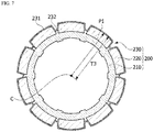
- FIGS. 6 and 7 are top cross-sectional views of the rotor taken along line B-B of FIG. 2 .
- the molding portion 230 of the rotor 200 is intended to reduce the difference in the proceeding speed of the mold material in the first region S1 and the second region S2 by reducing the fluid sectional area in the first area S1 shown in FIG. 5 .
- a distance from the center C of the rotor core 210 to an outer surface of the molding portion 230 through a center P1 of the guide protrusion 211 is referred to as a first distance T1.
- a distance from the center C of the rotor core 210 to the outer surface of the molding portion 230 through a center P2 of the magnet 220 is referred to as a second distance T2.
- a distance from the center C of the rotor core 210 to an outer surface of the magnet 220 is referred to as a third distance T3.
- the first distance T1 is formed to be smaller than the second distance T2 in the molding portion 230.
- the first distance T1 is formed to be smaller than the third distance T3.
- the molding portion 230 may include a convex portion 231 and a concave portion 232.
- the molding portion 230 may include the convex portion 231 disposed to protrude relatively outward and the concave portion 232 disposed to be concave relatively inward.
- the convex portions 231 and the concave portions 232 are alternately arranged along a circumferential direction of the rotor 200.
- a plurality of such concave portions 232 may be arranged to be symmetrical on the basis of the center of the rotor core 210. This is for keeping balance of the motor.
- the convex portions 231 are arranged in the second region S2 (refer to FIG. 5 ) which is an area outside the magnet 220.
- the concave portions 232 are arranged in the first region S1 which is an area between the magnet 220 and the magnet 220. Accordingly, the number of the convex portions 231 is equal to the number of the magnets 220. Also, the number of the convex portions 231 is equal to the number of the guide protrusions 211.
- FIG. 8 is a view illustrating a thickness of a molding portion.
- a center P3 of the concave portion 232 may be disposed outside the rotor core 210.
- a shape of an outer circumferential surface of the molding portion 230 may correspond to a shape of an outer circumferential surface of the magnet 220.
- a thickness t1 of the convex portion 231 may be equal to a thickness t2 of the concave portion 232.
- the thickness t1 of the convex portion 231 is equal to the thickness t2 of the concave portion 232, since there is no difference between the proceeding speed of the mold material in the first region S1 and the proceeding speed of the mold material in the second region S2, occurrence of the weld line may be minimized.
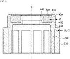
- FIG. 9 is a view illustrating a thickness of the molding portion at the sensor magnet and a thickness of the molding portion at the rotor.
- a thickness t3 of the molding portion 230 disposed outside the sensor magnet 400 is smaller than the thicknesses t1 and t2 of the molding portion 230 disposed outside the rotor core 210. Since the molding portion 230 disposed outside the sensor magnet 400 has a relatively greater thickness t3, even when a weld line occurs in a corresponding area, a possibility of occurrence of cracks is low.
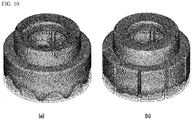
- FIG. 10 is a view in which a proceeding status of a molding portion in a general rotor and a proceeding status of the molding portion in the rotor of the motor according to the first embodiment are compared.
- FIG. 10A is a view illustrating the proceeding status of the molding portion in the general rotor.
- the proceeding speed of the mold material in the first region S1 is slower than the proceeding speed of the mold material in the second region S2 (refer to FIG. 5 ). This is because the fluid sectional area outside the magnet is smaller than the fluid sectional area between the magnet and the magnet.
- FIG. 10B is a view in which the proceeding statuses of the molding portion in the rotor of the motor according to the first embodiment are compared.
- FIG. 11 is a view in which a weld line occurrence state of a molding portion in a general rotor and a weld line occurrence state of the molding portion in the rotor of the motor according to the first embodiment are compared.
- FIG. 11A is a view illustrating the weld line occurrence state of the molding portion in the general rotor
- FIG. 11B is a view illustrating the weld line occurrence state of the molding portion in the rotor of the motor according to the first embodiment.
- FIG. 11A it may be seen that a lot of such weld lines occur in the molding portion disposed outside the rotor.
- FIG. 11B it may be seen that a weld line hardly occurs in the molding portion disposed outside the rotor according to the first embodiment.
- FIG. 12 is a view of a motor according to a second embodiment.
- the motor according to the second embodiment may include a shaft 1000, a rotor 1200, and a stator 1300.
- the rotor 1200 and the stator 1300 cause an electrical interaction.
- the rotor 1200 rotates and the shaft 1000 rotates in line therewith.
- the shaft 1000 may be connected to a DCT and provide power.
- the DCT is a system with dual clutches in which first, third, and fifth gears may be implemented using power transmitted through one clutch and second, fourth, and sixth gears may be implemented using power transmitted through the other clutch.
- the DCT may selectively receive power of the shaft 1000.
- the DCT has features of providing fuel efficiency higher than that of a conventional manual transmission vehicle as well as convenient drivability and a soft transmission sense like those of a conventional automatic transmission vehicle.
- FIG. 13 is a view of the rotor of the motor according to the second embodiment.
- the rotor 1200 may include a rotor core 1210, magnets 1220, and a can member 1230.
- a sensor magnet 1400 is disposed above the rotor core 1210.
- the sensor magnet 1400 is coupled with the shaft 1000.
- the magnets 1220 may be coupled with an outer circumferential surface of the rotor core 1210.
- the sensor magnet 1400 may be magnetized with a plurality of poles.
- the sensor magnet 1400 is disposed above the rotor core 1210 such that a center thereof is equal to a center C of the rotor core 1210.
- the sensor magnet 1400 performs a function of causing a signal for detecting a rotational position of the rotor core 1210.
- the sensor magnet 1400 is implemented in a ring shape. Also, the sensor magnet 1400 may include samarium cobalt.
- the can member 1230 performs a function of fixing the magnets 1220 not to be separated from the rotor core 1210 by surrounding the magnets 1220. Also, the can member 1230 prevents the magnets 1220 from being exposed and physically and chemically protects the rotor core 1210 and the magnets 1220.
- the can member 1230 may include a first can 1231 and a second can 1232.
- the first can 1231 may be mounted on one end side of the rotor core 1210.
- the second can 1232 may be mounted on the other end side of the rotor core 1210.
- the first can 1231 and the second can 1232 may have cylindrical shapes, and top ends thereof may be bent to come into contact with one cross section and the other cross section of the rotor core 1210, respectively.
- the first can 1231 and the second can 1232 are arranged such that a bottom end of the first can 1231 faces and comes in contact with a bottom end of the second can 1232 when the first can 1231 and the second can 1232 are mounted on the rotor core 1210.
- the first can 1231 and the second can 1232 include groove portions 1231a and 1320a, respectively.
- the groove portions 1231a and 1320a may be arranged lengthwise in a height direction of the can member 1230.
- the height direction of the can member 1230 is a direction parallel to an axial direction of the shaft 1000 when the shaft 1000 is coupled with the rotor 1200.
- the groove portions 1231a and 1320a are arranged concavely on an outer circumferential surface of the can member 1230.
- FIG. 14 is a horizontal cross-sectional view illustrating the rotor shown in FIG. 12
- FIG. 15 is a plan view illustrating the rotor shown in FIG. 12 .
- the groove portions 1231a and 1320a are located between the magnet 1200 and the magnet 220 in a circumferential direction of the rotor 1200.
- the number of such groove portions 1231a and 1320a may be two.
- the two groove portions 1231a and 1320a may be arranged to be symmetrical on the basis of the center C of the rotor 1200. Meanwhile, the number of the groove portions 1231a and 1320a may be changed.
- a maximum number of the groove portions 1231a and 1320a may be equal to the number of the magnets 1220.
- the number of the groove portions 1231a and 1320a is one, a problem may occur in balance and a fixing force.
- the number of the groove portions 1231a and 1320a is excessively great, it is difficult to couple the can member 1230 with the rotor core 1210.
- the can member 1230 may forcibly fit in the rotor core 1210 and the magnets 1220.
- the groove portions 1231a and 1320a of the can member 1230 move along a gap between the magnet 1220 and the magnet 1200.
- the groove portions 1231a and 1320a of the can member 1230 forcibly fits in not only the magnets 1220 but also the rotor core 1210.
- the groove portions 1231a and 1320a may include bottom portions 1310aa and 1320aa and side portions 1310bb and 1320bb formed to be bent from both ends of the bottom portions 1310aa and 1320aa.
- the bottom portions 1310aa and 1320aa come into contact with the rotor core 1210.
- the rotor core 1210 may include guide protrusions 1110, and the bottom portions 1310aa and 1320aa may come into surface contact with the guide protrusions 1110.
- the side portions 1310bb and 1320bb are arranged to be spaced apart from the magnets 1220, and a space may be disposed between the side portions 1310bb and 1320bb and the magnets 1220.
- the guide protrusions 1110 protrude from the outer circumferential surface of the rotor core 1210 and guides and fixes the magnets 1220.
- the guide protrusions 1110 may be arranged at certain intervals along a circumferential direction of the rotor core 1210.
- FIG. 16 is a view illustrating a first weld bead and a second weld bead.
- a first weld bead 10 is formed in the groove portions 1231a and 1320a.
- a bottom end 1310b of the groove portion 1310a of the first can 1231 comes into contact with a bottom end 1320b of the groove portion 1320a of the second can 1232.
- the first weld bead 10 is formed.
- the first weld bead 10 is formed by welding not only the groove portion 1310a of the first can 1231 and the groove portion 1320a of the second can 1232 but also the guide protrusion 1110 of the rotor core 1210.
- second weld beads 20 are formed on the groove portions 1231a and 1320a.
- the second weld beads 20 may be generated by welding the bottom portion 1310aa of the groove portion 1310a of the first can 1231 with the guide protrusion 1110.
- the second weld beads 20 may be generated by welding the bottom portion 1320aa of the groove portion 1320a of the second can 1232 with the guide protrusion 1110.
- the coupling force between the rotor core 1210 and the magnets 1220 may be further increased.
- FIG. 17 is a view illustrating the first weld bead which protrudes.
- a distance L1 from the center C of the rotor core 1210 to an outer circumferential surface of the first weld bead 10 may be smaller than a distance L2 from the center of the rotor core 1210 to an outer circumferential surface of the magnet 1200 and greater than a distance L3 from the center of the rotor core 1210 to an outer circumferential surface of the groove portions 1231aa and 1320a.
- the first weld bead 10 may have a convex shape.
- FIG. 18 is a block diagram illustrating a method of manufacturing the motor according to the second embodiment
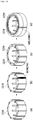
- FIG. 19 is a view illustrating a process of manufacturing the motor according to the second embodiment.
- the rotor core 1210 is manufactured. Referring to FIGS. 18 and 19B , an adhesive is applied to an outer circumferential surface of the rotor core 1210. Also, referring to FIGS. 18 and 19C , the magnets 1220 are attached to the outer circumferential surface of the rotor core 1210 (S100).
- the rotor core 1210 is covered with the can member 1230 such that the groove portions 1231a and 1320a forcibly fit in between the magnet 1200 and the magnet 1200 (S200).
- a joint part between the first can 1231 and the second can 1232 is welded (S300).
Landscapes
- Engineering & Computer Science (AREA)
- Power Engineering (AREA)
- Microelectronics & Electronic Packaging (AREA)
- General Engineering & Computer Science (AREA)
- Mechanical Engineering (AREA)
- Permanent Field Magnets Of Synchronous Machinery (AREA)
Abstract
Description
- Embodiments related to a rotor and a motor including the same.
- A transmission of a vehicle is a transmission system manually operated according to a user's clutch manipulation or automatically operated according to a velocity due to a transmission operation and includes a motor.
- The motor of the transmission system may include a sensor magnet installed above a rotor. The sensor magnet has a ring shape including an outer circumferential surface and an inner circumferential surface. The sensor magnet is installed above the rotor and performs a function of indicating a position of the rotor. The sensor magnet and the rotor may be fixed using a molding portion. However, there is a problem that a weld line occurs on the molding portion during a process of injection molding the molding portion. Since weld lines cause cracks in the molding portion, it is preferable to minimize the weld lines.
- Also, the rotor of the motor may include magnets. Magnets may be attached to an outer circumferential surface of a rotor core. In the case of the motor, due to a structural property thereof, a variety of protector types such as molding, cans, tubes, and the like are applied to improve durability of assembling magnets.
- Among them, in the case of a can type, cans having a cup shape are coupled with an upper part and a lower part of an outer circumferential surface of a rotor so as to protect the rotor as well as prevent magnets from being detached.
- However, in order to assemble the rotor inside the cans, it is necessary to apply an adhesive to insides of the cans. However, the operation of applying an adhesive makes a process of assembling the rotor complicated.
- Meanwhile, in the case a molding type, chemical resistance is necessary such that there is a great limit in materials thereof and a risk of generating cracks is great.
- The present invention is directed to providing a rotor capable of preventing a crack in a molding portion by minimizing weld lines of the molding portion and a motor including the rotor.
- The present invention is directed to providing a motor capable of protecting magnets using a can without an operation of applying an adhesive thereto.
- Aspects of the present invention are not limited to the above-stated aspects and other unstated aspects of the present invention will be understood by those skilled in the art from a following description.
- One aspect of the present invention provides a rotor including a rotor core, a plurality of magnets arranged outside the rotor core, and a molding portion disposed outside the plurality of magnets. Here, the rotor core includes a plurality of guide protrusions disposed between the plurality of magnets. Also, a distance from a center of the rotor core to an outer surface of the molding portion through a center of the guide protrusion is smaller than a distance from the center of the rotor core to the outer surface of the molding portion through a center of one of the plurality of magnets.
- The rotor may further include a sensor magnet disposed above the rotor core. Here, the molding portion may be disposed outside the sensor magnet, and a thickness of the molding portion disposed outside the plurality of magnets on the basis of a radial direction of the center of the rotor core may be smaller than a thickness of the molding portion disposed outside the sensor magnet.
- A cross section of the molding portion taken along a direction perpendicular to a longitudinal direction of the magnet may include a convex portion and a concave portion, and the convex portions and the concave portions may be alternately arranged.
- A center of the concave portion may be disposed outside the rotor core.
- The numbers of the convex portions, the magnets, and the guide protrusions may be equal to one another.
- The distance from the center of the rotor core to the outer surface of the molding portion through the center of the guide protrusion may be smaller than a distance from the center of the rotor core to an outer surface of the magnet.
- A shape of an outer circumferential surface of the mold portion may correspond to a shape of an outer circumferential surface of the magnet.
- A curvature of the outer circumferential surface of the magnet and a curvature of an outer circumferential surface of the molding portion may include the same part.
- A thickness of the convex portion may be equal to a thickness of the concave portion.
- The concave portions may be arranged to be symmetrical on the basis of the center of the rotor core.
- Another aspect of the present invention provides a motor including a shaft, a rotor including a hole in which the shaft is disposed, and a stator disposed outside the rotor. Here, the rotor includes a rotor core, a plurality of magnets arranged outside the rotor core, and a molding portion disposed outside the plurality of magnets. The rotor core includes a plurality of guide protrusions disposed between the plurality of magnets. Also, a distance from a center of the rotor core to an outer surface of the molding portion through a center of the guide protrusion is smaller than a distance from the center of the rotor core to the outer surface of the molding portion through a center of one of the plurality of magnets.
- Still another aspect of the present invention provides a motor including a shaft, a rotor including a hole in which the shaft is disposed, and a stator disposed outside the rotor. Here, the rotor includes a rotor core coupled with the shaft, magnets coupled with the rotor core, and a can member surrounding the rotor core and the magnets. The can member includes groove portions. The groove portions are concavely disposed between the magnet and the magnet and on an outer circumferential surface of the can member toward a center of the rotor and arranged along a height direction of the can member. The can member includes a first can and a second can disposed at both ends of the rotor core. Also, the first can and the second can are arranged such that a bottom end of the groove portion of the first can comes into contact with a bottom end of the groove portion of the second can, and the first can and the second can include a first weld bead disposed through the bottom end of the groove portion of the first can and the bottom end of the groove portion of the second can.
- The rotor core may include guide protrusions, and the guide protrusions may protrude from an outer circumferential surface of the rotor core in a radial direction of the rotor core and be arranged along an axial direction of the shaft.
- The groove portion may include a bottom surface and sidewalls disposed on both ends of the bottom surface.
- The groove portion may include a bottom surface and sidewalls disposed on both ends of the bottom surface, and the bottom surface of the groove portion may come into contact with the guide protrusions.
- The sidewalls may be disposed to be spaced apart from the magnets.
- The groove portion may forcibly fit in between the magnet and the magnet on the basis of a circumferential direction of the rotor.
- A plurality of second weld beads may be disposed on the bottom surface of the groove portion.
- A plurality of such groove portions may be arranged and be arranged to be symmetrical on the basis of the center of the rotor.
- A distance from a center of the rotor core to an outer circumferential surface of the first weld bead may be smaller than a distance from the center of the rotor core to an outer circumferential surface of the magnet and be greater than a distance from the center of the rotor core to an outer circumferential surface of the groove portion.
- The can member may come into surface contact with the guide protrusions.
- Yet another embodiment of the present invention provides a method including attaching magnets to the rotor core, covering the rotor core with the can member such that the groove portion forcibly fits in between the magnet and the magnet, and welding a joint part between the first can and the second can.
- According to embodiments, an advantageous effect of preventing a crack in a molding portion by minimizing weld lines of the molding portion may be provided.
- According to embodiments, an advantageous effect of excluding an operation of applying an adhesive to a can may be provided.
-
-
FIG. 1 is a view of a motor according to a first embodiment; -
FIG. 2 is a view illustrating a rotor shown inFIG. 1 ; -
FIG. 3 is a side cross-sectional view of the rotor taken along line A-A ofFIG. 2 ; -
FIG. 4 is a view illustrating an injection flow; -
FIG. 5 is a top cross-sectional view of a rotor core and magnets taken along line B-B ofFIG. 2 ; -
FIGS. 6 and7 are top cross-sectional views of the rotor taken along line B-B ofFIG. 2 ; -
FIG. 8 is a view illustrating a thickness of a molding portion; -
FIG. 9 is a view illustrating a thickness of the molding portion at a sensor magnet and a thickness of the molding portion at the rotor; -
FIG. 10 is a view in which a proceeding status of a molding portion in a general rotor and a proceeding status of the molding portion in the rotor of the motor according to the first embodiment are compared; -
FIG. 11 is a view in which a weld line occurrence state of a molding portion in a general rotor and a weld line occurrence state of the molding portion in the rotor of the motor according to the first embodiment are compared; -
FIG. 12 is a view of a motor according to a second embodiment; -
FIG. 13 is a view of a rotor of the motor according to the second embodiment; -
FIG. 14 is a horizontal cross-sectional view illustrating the rotor shown inFIG. 12 ; -
FIG. 15 is a plan view illustrating the rotor shown inFIG. 12 ; -
FIG. 16 is a view illustrating a first weld bead and second weld beads; -
FIG. 17 is a view illustrating the first weld bead which protrudes; -
FIG. 18 is a block diagram illustrating a method of manufacturing the motor according to the second embodiment; and -
FIG. 19 is a view illustrating a process of manufacturing the motor according to the second embodiment. - Hereinafter, exemplary embodiments of the present invention will be described in detail with reference to the drawings.
- However, the present invention is not limited to the embodiments disclosed below, but can be implemented in various forms. One or more of components of the embodiments may be selectively combined or substituted with one another without departing from the scope of the technical concept of the present invention.
- Also, unless defined otherwise, the terms (including technical and scientific terms) used herein may be used as meanings capable of being commonly understood by one of ordinary skill in the art. Also, terms defined in generally used dictionaries may be construed in consideration of the contextual meanings of the related art.
- Also, the terms used herein are intended to describe the embodiments but not intended to restrict the present invention.
- Throughout the specification, unless stated otherwise particularly, singular forms include plural forms. When it is stated that at least one (or one or more) of A, B, and C, it may include one or more of all combinations of A, B, and C.
- Also, in describing components of the embodiments of the present invention, the terms such as first, second, A, B, (a), (b), and the like may be used.
- These terms are merely for distinguishing one element from another, and the essential, order, sequence, and the like of corresponding elements are not limited by the terms.
- Also, when it is stated that one element is "connected," or "coupled" to another, the element may not only be directly connected or coupled to the other element but also be connected or coupled to the other element with another intervening element.
- Also, when it is stated that an element is formed or disposed "above (on) or below (beneath)" another element, the two elements may not only come into direct contact with each other but also still another element may be formed or disposed between the two elements. Also, being "above (on) or below (beneath)" may include not only being an upward direction but also being a downward direction on the basis of one element.
-
FIG. 1 is a view of a motor according to a first embodiment. - Referring to
FIG. 1 , the motor according to the first embodiment may include ashaft 100, arotor 200, and astator 300. - The
rotor 200 and thestator 300 cause an electrical interaction. When the electrical interaction is caused, therotor 200 rotates and theshaft 100 rotates in line therewith. Theshaft 100 may be connected to a dual-clutch transmission (DCT) and provide power. - Here, unlike a single plate clutch transmission loaded in a conventional manual transmission vehicle, the DCT is a system with dual clutches in which first, third, and fifth gears may be implemented using power transmitted through one clutch and second, fourth, and sixth gears may be implemented using power transmitted through the other clutch.
- The DCT may selectively receive power of the
shaft 100. - The DCT has features of providing fuel efficiency higher than that of a conventional manual transmission vehicle as well as convenient drivability and a soft transmission sense like those of a conventional automatic transmission vehicle.
-
FIG. 2 is a view illustrating the rotor shown inFIG. 1 , andFIG. 3 is a side cross-sectional view of the rotor taken along line A-A ofFIG. 2 . - Referring to
FIGS. 2 and3 , therotor 200 is disposed inside thestator 300. - The
rotor 200 may include arotor core 210,magnets 220, and amolding portion 230. - A
sensor magnet 400 is disposed above therotor core 210. Themolding portion 230 combines therotor core 210 with thesensor magnet 400. Thesensor magnet 400 may be concentrically disposed above therotor core 210. Themagnets 220 may be coupled with an outer circumferential surface of therotor core 210. - The
sensor magnet 400 may be magnetized with a plurality of poles. Thesensor magnet 400 is disposed above therotor core 210 such that a center thereof is equal to a center C of therotor core 210. Thesensor magnet 400 performs a function of causing a signal for detecting a rotational position of therotor core 210. Thesensor magnet 400 is implemented in a ring shape. Thesensor magnet 400 may include a hole in the center thereof through which theshaft 100 passes. Also, thesensor magnet 400 may include samarium cobalt. - The
molding portion 230 combines therotor core 210 with thesensor magnet 400. Themolding portion 230 may be formed to surround both therotor core 210 and thesensor magnet 400. Themolding portion 230 may be formed through double injection while including therotor core 210 and thesensor magnet 400. Themolding portion 230 has a shape surrounding atop surface 410, an outercircumferential surface 420, abottom surface 430, and an innercircumferential surface 440 of thesensor magnet 400. Here, themolding portion 230 may be embodied to surround only a part of the innercircumferential surface 440 of thesensor magnet 400 on the basis of an axial direction. Also, themolding portion 230 may be embodied to surround only a part of thetop surface 410 in a radial direction on the basis of the center C of thesensor magnet 400. This is for securing pole detection performance of thesensor magnet 400. -
FIG. 4 is a view illustrating an injection flow. - Referring to
FIG. 4 , injection molding is performed while themagnets 220 are attached to the outer circumferential surface of therotor core 210 and thesensor magnet 400 is disposed above therotor core 210. An injection gate is disposed above thesensor magnet 400 such that a mold material flows from an upper side on which thesensor magnet 400 is located to a lower side on which therotor core 210 is located. - Here, an injection flow at the
rotor 200 may be divided into an injection flow A which flows outside themagnets 220 and an injection flow B which flows between themagnet 220 and themagnet 220. -
FIG. 5 is a top cross-sectional view of a rotor core and magnets taken along line B-B ofFIG. 2 . - Referring to
FIGS. 4 and5 , M ofFIG. 5 is a boundary line which indicates an outer circumferential surface of a general molding portion. A first region S1 and a second region S2 have different injection flows. - The first region S1 is an area, in which a
guide protrusion 211 is located, and corresponds to a space between themagnet 220 and themagnet 220. The injection flow B which flows between themagnet 220 and themagnet 220 proceeds toward the first region S1. The second region S2 corresponds to an outside of themagnet 220. The injection flow A which flows outside themagnet 220 proceeds toward the second region S2. - A fluid sectional area of the first region S1 is greater than a fluid sectional area of the second region S2. Accordingly, a mold material quickly moves downward in the first region S1 and relatively slowly moves downward in the second region S2. A weld line may occur in an axial direction due to a difference between a proceeding speed of the mold material in the first region S1 and a proceeding speed of the mold material in the second region S2.
-
FIGS. 6 and7 are top cross-sectional views of the rotor taken along line B-B ofFIG. 2 . - Referring to
FIGS. 5 to 7 , themolding portion 230 of therotor 200 is intended to reduce the difference in the proceeding speed of the mold material in the first region S1 and the second region S2 by reducing the fluid sectional area in the first area S1 shown inFIG. 5 . - A distance from the center C of the
rotor core 210 to an outer surface of themolding portion 230 through a center P1 of theguide protrusion 211 is referred to as a first distance T1. A distance from the center C of therotor core 210 to the outer surface of themolding portion 230 through a center P2 of themagnet 220 is referred to as a second distance T2. A distance from the center C of therotor core 210 to an outer surface of themagnet 220 is referred to as a third distance T3. - The first distance T1 is formed to be smaller than the second distance T2 in the
molding portion 230. In addition, the first distance T1 is formed to be smaller than the third distance T3. - Accordingly, the
molding portion 230 may include aconvex portion 231 and aconcave portion 232. On the basis of a horizontal cross section of themolding portion 230 taken along in a direction perpendicular to a longitudinal direction of themagnet 220, themolding portion 230 may include theconvex portion 231 disposed to protrude relatively outward and theconcave portion 232 disposed to be concave relatively inward. Theconvex portions 231 and theconcave portions 232 are alternately arranged along a circumferential direction of therotor 200. A plurality of suchconcave portions 232 may be arranged to be symmetrical on the basis of the center of therotor core 210. This is for keeping balance of the motor. - The
convex portions 231 are arranged in the second region S2 (refer toFIG. 5 ) which is an area outside themagnet 220. Theconcave portions 232 are arranged in the first region S1 which is an area between themagnet 220 and themagnet 220. Accordingly, the number of theconvex portions 231 is equal to the number of themagnets 220. Also, the number of theconvex portions 231 is equal to the number of theguide protrusions 211. -
FIG. 8 is a view illustrating a thickness of a molding portion. - Referring to
FIG. 8 , a center P3 of theconcave portion 232 may be disposed outside therotor core 210. - A shape of an outer circumferential surface of the
molding portion 230 may correspond to a shape of an outer circumferential surface of themagnet 220. For example, a part where a curvature R1 of the outer circumferential surface of themagnet 220 is equal to a curvature R2 of the outer circumferential surface of themolding portion 230 exists in themolding portion 230. - In a point of view on the basis of a thickness of the
molding portion 230, a thickness t1 of theconvex portion 231 may be equal to a thickness t2 of theconcave portion 232. When the thickness t1 of theconvex portion 231 is equal to the thickness t2 of theconcave portion 232, since there is no difference between the proceeding speed of the mold material in the first region S1 and the proceeding speed of the mold material in the second region S2, occurrence of the weld line may be minimized. -
FIG. 9 is a view illustrating a thickness of the molding portion at the sensor magnet and a thickness of the molding portion at the rotor. - Referring to
FIG. 9 , a thickness t3 of themolding portion 230 disposed outside thesensor magnet 400 is smaller than the thicknesses t1 and t2 of themolding portion 230 disposed outside therotor core 210. Since themolding portion 230 disposed outside thesensor magnet 400 has a relatively greater thickness t3, even when a weld line occurs in a corresponding area, a possibility of occurrence of cracks is low. -
FIG. 10 is a view in which a proceeding status of a molding portion in a general rotor and a proceeding status of the molding portion in the rotor of the motor according to the first embodiment are compared. -
FIG. 10A is a view illustrating the proceeding status of the molding portion in the general rotor. - Referring to
FIG. 10A , it may be seen that the proceeding speed of the mold material in the first region S1 (refer toFIG. 5 ) is slower than the proceeding speed of the mold material in the second region S2 (refer toFIG. 5 ). This is because the fluid sectional area outside the magnet is smaller than the fluid sectional area between the magnet and the magnet. -
FIG. 10B is a view in which the proceeding statuses of the molding portion in the rotor of the motor according to the first embodiment are compared. - Referring to
FIG. 10B , there is no difference between the proceeding speed of the mold material in the first region S1 (refer toFIG. 5 ) and the proceeding speed of the mold material in the second region S2 (refer toFIG. 5 ). This is because the fluid sectional area outside the magnet is equal to the fluid sectional area between the magnet and the magnet. In this case, the weld line is minimized on an outer surface of therotor 200. -
FIG. 11 is a view in which a weld line occurrence state of a molding portion in a general rotor and a weld line occurrence state of the molding portion in the rotor of the motor according to the first embodiment are compared. -
FIG. 11A is a view illustrating the weld line occurrence state of the molding portion in the general rotor, andFIG. 11B is a view illustrating the weld line occurrence state of the molding portion in the rotor of the motor according to the first embodiment. - Referring to
FIG. 11A , it may be seen that a lot of such weld lines occur in the molding portion disposed outside the rotor. On the other hand, referring toFIG. 11B , it may be seen that a weld line hardly occurs in the molding portion disposed outside the rotor according to the first embodiment. -
FIG. 12 is a view of a motor according to a second embodiment. - Referring to
FIG. 12 , the motor according to the second embodiment may include a shaft 1000, arotor 1200, and astator 1300. - The
rotor 1200 and thestator 1300 cause an electrical interaction. When the electrical interaction is caused, therotor 1200 rotates and the shaft 1000 rotates in line therewith. The shaft 1000 may be connected to a DCT and provide power. - Here, unlike a single plate clutch transmission loaded in a conventional manual transmission vehicle, the DCT is a system with dual clutches in which first, third, and fifth gears may be implemented using power transmitted through one clutch and second, fourth, and sixth gears may be implemented using power transmitted through the other clutch.
- The DCT may selectively receive power of the shaft 1000.
- The DCT has features of providing fuel efficiency higher than that of a conventional manual transmission vehicle as well as convenient drivability and a soft transmission sense like those of a conventional automatic transmission vehicle.
-
FIG. 13 is a view of the rotor of the motor according to the second embodiment. - Referring to
FIGS. 12 and13 , therotor 1200 according to the second embodiment may include arotor core 1210,magnets 1220, and acan member 1230. Asensor magnet 1400 is disposed above therotor core 1210. Thesensor magnet 1400 is coupled with the shaft 1000. Themagnets 1220 may be coupled with an outer circumferential surface of therotor core 1210. - The
sensor magnet 1400 may be magnetized with a plurality of poles. Thesensor magnet 1400 is disposed above therotor core 1210 such that a center thereof is equal to a center C of therotor core 1210. Thesensor magnet 1400 performs a function of causing a signal for detecting a rotational position of therotor core 1210. Thesensor magnet 1400 is implemented in a ring shape. Also, thesensor magnet 1400 may include samarium cobalt. - The
can member 1230 performs a function of fixing themagnets 1220 not to be separated from therotor core 1210 by surrounding themagnets 1220. Also, thecan member 1230 prevents themagnets 1220 from being exposed and physically and chemically protects therotor core 1210 and themagnets 1220. - The
can member 1230 may include afirst can 1231 and asecond can 1232. Thefirst can 1231 may be mounted on one end side of therotor core 1210. Also, thesecond can 1232 may be mounted on the other end side of therotor core 1210. Thefirst can 1231 and thesecond can 1232 may have cylindrical shapes, and top ends thereof may be bent to come into contact with one cross section and the other cross section of therotor core 1210, respectively. - The
first can 1231 and thesecond can 1232 are arranged such that a bottom end of thefirst can 1231 faces and comes in contact with a bottom end of thesecond can 1232 when thefirst can 1231 and thesecond can 1232 are mounted on therotor core 1210. Also, thefirst can 1231 and thesecond can 1232 includegroove portions 1231a and 1320a, respectively. Thegroove portions 1231a and 1320a may be arranged lengthwise in a height direction of thecan member 1230. The height direction of thecan member 1230 is a direction parallel to an axial direction of the shaft 1000 when the shaft 1000 is coupled with therotor 1200. Also, thegroove portions 1231a and 1320a are arranged concavely on an outer circumferential surface of thecan member 1230. -
FIG. 14 is a horizontal cross-sectional view illustrating the rotor shown inFIG. 12 , andFIG. 15 is a plan view illustrating the rotor shown inFIG. 12 . - Referring to
FIGS. 12 to 15 , thegroove portions 1231a and 1320a are located between themagnet 1200 and themagnet 220 in a circumferential direction of therotor 1200. The number ofsuch groove portions 1231a and 1320a may be two. The twogroove portions 1231a and 1320a may be arranged to be symmetrical on the basis of the center C of therotor 1200. Meanwhile, the number of thegroove portions 1231a and 1320a may be changed. A maximum number of thegroove portions 1231a and 1320a may be equal to the number of themagnets 1220. When the number of thegroove portions 1231a and 1320a is one, a problem may occur in balance and a fixing force. On the other hand, when the number of thegroove portions 1231a and 1320a is excessively great, it is difficult to couple thecan member 1230 with therotor core 1210. - The
can member 1230 may forcibly fit in therotor core 1210 and themagnets 1220. When therotor core 1210 and themagnets 1220 are covered with thecan member 1230, thegroove portions 1231a and 1320a of thecan member 1230 move along a gap between themagnet 1220 and themagnet 1200. Thegroove portions 1231a and 1320a of thecan member 1230 forcibly fits in not only themagnets 1220 but also therotor core 1210. - The
groove portions 1231a and 1320a may include bottom portions 1310aa and 1320aa and side portions 1310bb and 1320bb formed to be bent from both ends of the bottom portions 1310aa and 1320aa. The bottom portions 1310aa and 1320aa come into contact with therotor core 1210. In detail, therotor core 1210 may include guide protrusions 1110, and the bottom portions 1310aa and 1320aa may come into surface contact with the guide protrusions 1110. The side portions 1310bb and 1320bb are arranged to be spaced apart from themagnets 1220, and a space may be disposed between the side portions 1310bb and 1320bb and themagnets 1220. - The guide protrusions 1110 protrude from the outer circumferential surface of the
rotor core 1210 and guides and fixes themagnets 1220. The guide protrusions 1110 may be arranged at certain intervals along a circumferential direction of therotor core 1210. -
FIG. 16 is a view illustrating a first weld bead and a second weld bead. - Referring to
FIGS. 12 and16 , afirst weld bead 10 is formed in thegroove portions 1231a and 1320a. When thefirst can 1231 and thesecond can 1232 are mounted on therotor core 1210, a bottom end 1310b of the groove portion 1310a of thefirst can 1231 comes into contact with a bottom end 1320b of the groove portion 1320a of thesecond can 1232. In this state, when welding is performed on a boundary between the bottom end 1310b of the groove portion 1310a of thefirst can 1231 and the bottom end 1320b of the groove portion 1320a of thesecond can 1232, thefirst weld bead 10 is formed. Thefirst weld bead 10 is formed by welding not only the groove portion 1310a of thefirst can 1231 and the groove portion 1320a of thesecond can 1232 but also the guide protrusion 1110 of therotor core 1210. - Consequently, as the
first can 1231, thesecond can 1232, and therotor core 1210 are coupled by welding, a coupling force through welding is added to a coupling force generated by forcibly fitting of thecan member 1230 such that a coupling force between therotor core 1210 and themagnets 1220 further increases. Accordingly, without applying an adhesive to thecan member 1230, robustness of thecan member 1230 may be secured. - Also, additionally,
second weld beads 20 are formed on thegroove portions 1231a and 1320a. Thesecond weld beads 20 may be generated by welding the bottom portion 1310aa of the groove portion 1310a of thefirst can 1231 with the guide protrusion 1110. Also, thesecond weld beads 20 may be generated by welding the bottom portion 1320aa of the groove portion 1320a of thesecond can 1232 with the guide protrusion 1110. - As the
first can 1231 is coupled with therotor core 1210 through welding and thesecond can 1232 is coupled with therotor core 1210 through welding, the coupling force between therotor core 1210 and themagnets 1220 may be further increased. -
FIG. 17 is a view illustrating the first weld bead which protrudes. - Meanwhile, referring to
FIG. 17 , a distance L1 from the center C of therotor core 1210 to an outer circumferential surface of thefirst weld bead 10 may be smaller than a distance L2 from the center of therotor core 1210 to an outer circumferential surface of themagnet 1200 and greater than a distance L3 from the center of therotor core 1210 to an outer circumferential surface of the groove portions 1231aa and 1320a. For example, thefirst weld bead 10 may have a convex shape. -
FIG. 18 is a block diagram illustrating a method of manufacturing the motor according to the second embodiment, andFIG. 19 is a view illustrating a process of manufacturing the motor according to the second embodiment. - Referring to
FIGS. 18 and19A , therotor core 1210 is manufactured. Referring toFIGS. 18 and19B , an adhesive is applied to an outer circumferential surface of therotor core 1210. Also, referring toFIGS. 18 and19C , themagnets 1220 are attached to the outer circumferential surface of the rotor core 1210 (S100). - Referring to
FIGS. 18 and19D , therotor core 1210 is covered with thecan member 1230 such that thegroove portions 1231a and 1320a forcibly fit in between themagnet 1200 and the magnet 1200 (S200). - Referring to
FIGS. 18 and19D , a joint part between thefirst can 1231 and thesecond can 1232 is welded (S300). - A rotor and a motor including the rotor according to one exemplary embodiment of the present invention have been described above in detail with reference to the attached drawings.
- The above description is exemplarily describing the technical concept of the present invention, and a variety of modifications, changes, and substitutions may be made by one of ordinary skill in the art to which the present invention pertains without departing from the essential features of the present invention. Accordingly, the embodiment disclosed herein and the attached drawings are intended not to limit but to describe the technical concept of the present invention, and the scope of the technical concept of the present invention is not limited to the embodiments and the attached drawings. The scope of the present invention should be construed by the following claims and all technical concepts within the equal range thereof should be construed as being included in the extent of right of the present invention.
Claims (10)
- A rotor comprising:a rotor core;a plurality of magnets arranged outside the rotor core; anda molding portion disposed outside the plurality of magnets,wherein the rotor core comprises a plurality of guide protrusions disposed between the plurality of magnets, andwherein a distance from a center of the rotor core to an outer surface of the molding portion through a center of the guide protrusion is smaller than a distance from the center of the rotor core to the outer surface of the molding portion through a center of one of the plurality of magnets.
- The rotor of claim 1, further comprising a sensor magnet disposed above the rotor core,
wherein the molding portion is disposed outside the sensor magnet, and a thickness of the molding portion disposed outside the plurality of magnets on the basis of a radial direction of the center of the rotor core is smaller than a thickness of the molding portion disposed outside the sensor magnet. - The rotor of claim 1, wherein a cross section of the molding portion taken along a direction perpendicular to a longitudinal direction of the magnet comprises a convex portion and a concave portion, and the convex portions and the concave portions are alternately arranged.
- The rotor of claim 3, wherein a center of the concave portion is disposed outside the rotor core.
- A motor comprising:a shaft;a rotor comprising a hole in which the shaft is disposed; anda stator disposed outside the rotor,wherein the rotor comprises:a rotor core;a plurality of magnets arranged outside the rotor core; anda molding portion disposed outside the plurality of magnets,wherein the rotor core comprises a plurality of guide protrusions disposed between the plurality of magnets, andwherein a distance from a center of the rotor core to an outer surface of the molding portion through a center of the guide protrusion is smaller than a distance from the center of the rotor core to the outer surface of the molding portion through a center of one of the plurality of magnets.
- A motor comprising:a shaft;a rotor comprising a hole in which the shaft is disposed; anda stator disposed outside the rotor,wherein the rotor comprises:a rotor core coupled with the shaft;magnets coupled with the rotor core; anda can member surrounding the rotor core and the magnets,wherein the can member comprises groove portions,wherein the groove portions are concavely disposed on an outer circumferential surface of the can member toward a center of the rotor between the magnet and the magnet and arranged along a height direction of the can member,wherein the can member comprises a first can and a second can disposed at both ends of the rotor core, andwherein the first can and the second can are arranged such that a bottom end of the groove portion of the first can comes into contact with a bottom end of the groove portion of the second can, and the first can and the second can comprise a first weld bead disposed through the bottom end of the groove portion of the first can and the bottom end of the groove portion of the second can.
- The motor of claim 6, wherein the rotor core comprises guide protrusions, and wherein the guide protrusions protrude from an outer circumferential surface of the rotor core in a radial direction of the rotor core and are arranged along an axial direction of the shaft.
- The motor of claim 6, wherein the groove portion comprises a bottom surface and sidewalls disposed on both ends of the bottom surface.
- The motor of claim 6, wherein the groove portion comprises a bottom surface and sidewalls disposed on both ends of the bottom surface, and the bottom surface of the groove portion comes into contact with the guide protrusions.
- The motor of claim 9, wherein the sidewalls are disposed to be spaced apart from the magnets.
Applications Claiming Priority (3)
| Application Number | Priority Date | Filing Date | Title |
|---|---|---|---|
| KR1020170098593A KR102510334B1 (en) | 2017-08-03 | 2017-08-03 | Rotor and Motor having the same |
| KR1020170113928A KR102517687B1 (en) | 2017-09-06 | 2017-09-06 | Motor and method for manufacturing of the same |
| PCT/KR2018/008590 WO2019027196A1 (en) | 2017-08-03 | 2018-07-30 | Rotor and motor comprising same |
Publications (3)
| Publication Number | Publication Date |
|---|---|
| EP3664256A1 true EP3664256A1 (en) | 2020-06-10 |
| EP3664256A4 EP3664256A4 (en) | 2020-08-12 |
| EP3664256B1 EP3664256B1 (en) | 2021-09-29 |
Family
ID=65232769
Family Applications (1)
| Application Number | Title | Priority Date | Filing Date |
|---|---|---|---|
| EP18840181.4A Active EP3664256B1 (en) | 2017-08-03 | 2018-07-30 | Motor comprising a rotor |
Country Status (4)
| Country | Link |
|---|---|
| US (1) | US11469641B2 (en) |
| EP (1) | EP3664256B1 (en) |
| CN (1) | CN111095737B (en) |
| WO (1) | WO2019027196A1 (en) |
Families Citing this family (3)
| Publication number | Priority date | Publication date | Assignee | Title |
|---|---|---|---|---|
| JP7266180B2 (en) * | 2019-05-15 | 2023-04-28 | パナソニックIpマネジメント株式会社 | Rotor and motor with same |
| CN114846726B (en) * | 2019-12-23 | 2026-04-24 | Lg伊诺特有限公司 | motor |
| EP4195460A1 (en) * | 2021-12-07 | 2023-06-14 | Siemens Gamesa Renewable Energy A/S | Rotor for a permanent magnet electrical machine |
Family Cites Families (16)
| Publication number | Priority date | Publication date | Assignee | Title |
|---|---|---|---|---|
| BE794848A (en) * | 1972-12-15 | 1973-05-29 | Pompey Acieries | MANUFACTURING PROCESS IMPROVING THE HOLDING OF REFRACTORY STEEL WELDED PARTS |
| JPH1066293A (en) * | 1996-08-12 | 1998-03-06 | Ebara Corp | Canned motor |
| JP2003299279A (en) * | 2002-03-29 | 2003-10-17 | Honda Motor Co Ltd | Brushless motor |
| JP2004072968A (en) * | 2002-08-09 | 2004-03-04 | Toyoda Mach Works Ltd | Rotor of motor and manufacturing method thereof |
| DE102004030063A1 (en) * | 2004-06-23 | 2006-03-16 | Heinz Leiber | Permanent magnet excited rotating field machine |
| EP2025050A2 (en) * | 2006-05-10 | 2009-02-18 | Jones, Robert, M. | Electric machine having segmented stator |
| JP4671997B2 (en) | 2007-10-23 | 2011-04-20 | 三菱電機株式会社 | Rotor for rotating electrical machine and method for manufacturing the same |
| JP2010063285A (en) | 2008-09-04 | 2010-03-18 | Nidec Shibaura Corp | Motor and manufacturing method thereof |
| KR101728543B1 (en) * | 2009-12-23 | 2017-04-20 | 엘지이노텍 주식회사 | Rotor of motor |
| DE112014004555A5 (en) * | 2013-10-01 | 2016-07-07 | Schaeffler Technologies AG & Co. KG | Positioning a molded stator for a clutch actuator or a gear actuator and introducing a rotor magnet in such an actuator |
| KR102297684B1 (en) * | 2014-12-23 | 2021-09-03 | 엘지이노텍 주식회사 | Rotor Assembly, the manufacturing method of Rotor Assembly and Motor having Rotor Assembly |
| KR102319204B1 (en) * | 2014-12-29 | 2021-10-29 | 엘지이노텍 주식회사 | Motor and Clutch actuator having the same |
| KR20160088033A (en) | 2015-01-15 | 2016-07-25 | 엘지전자 주식회사 | Mobile terminal and method for controlling the same |
| KR102489300B1 (en) * | 2015-09-14 | 2023-01-17 | 엘지이노텍 주식회사 | Cans member and the rotor assembly having the same |
| KR102485022B1 (en) | 2015-10-26 | 2023-01-05 | 엘지이노텍 주식회사 | Rotor core assembly, rotor assembly and motor having the same |
| US10432044B2 (en) * | 2015-11-02 | 2019-10-01 | Denso Corporation | Rotor including stacked cores, motor, method for manufacturing rotor, and method for manufacturing motor |
-
2018
- 2018-07-30 CN CN201880057138.1A patent/CN111095737B/en active Active
- 2018-07-30 EP EP18840181.4A patent/EP3664256B1/en active Active
- 2018-07-30 US US16/636,142 patent/US11469641B2/en active Active
- 2018-07-30 WO PCT/KR2018/008590 patent/WO2019027196A1/en not_active Ceased
Also Published As
| Publication number | Publication date |
|---|---|
| US11469641B2 (en) | 2022-10-11 |
| EP3664256B1 (en) | 2021-09-29 |
| WO2019027196A1 (en) | 2019-02-07 |
| EP3664256A4 (en) | 2020-08-12 |
| US20200259391A1 (en) | 2020-08-13 |
| CN111095737B (en) | 2022-08-30 |
| CN111095737A (en) | 2020-05-01 |
Similar Documents
| Publication | Publication Date | Title |
|---|---|---|
| EP3664256A1 (en) | Rotor and motor comprising same | |
| JP5243385B2 (en) | Torque sensor | |
| US10088377B2 (en) | Torque sensor device | |
| CN106715974A (en) | Hydraulic or pneumatic operating device for operating actuators in a motor vehicle transmission | |
| US9410624B2 (en) | Bi-directional clip seal piston | |
| EP3144549A1 (en) | Dust cover for ball joint | |
| KR20130002933A (en) | Static sealing device for wheel hub assemblies connected to constant velocity joints | |
| US20150048701A1 (en) | Rotor Including Segmented Yoke | |
| CN104969037A (en) | Resolver stator and resolver | |
| EP3736539A1 (en) | Sensing device | |
| EP3937349A1 (en) | Stator and motor | |
| US20190238009A1 (en) | Stator for rotary electric machine | |
| KR102517687B1 (en) | Motor and method for manufacturing of the same | |
| US10316896B2 (en) | Centering sleeve for bearing and centering a shaft end | |
| JP2022174612A (en) | transformer | |
| KR20180050917A (en) | Plate Type Heat Exchanger | |
| KR20190014742A (en) | Rotor and Motor having the same | |
| US20190393746A1 (en) | Rotor and motor | |
| KR101611800B1 (en) | Pipe coupling for fuel tank | |
| WO2011008029A9 (en) | Motor cover and motor comprising same | |
| WO2006001118A1 (en) | Annular member | |
| KR102105643B1 (en) | Torque sensor unit | |
| CN209626147U (en) | Waterproof construction and starter relay | |
| KR101891666B1 (en) | Magnetic fixing device Having Motor | |
| CN223191112U (en) | electromagnetic coil |
Legal Events
| Date | Code | Title | Description |
|---|---|---|---|
| STAA | Information on the status of an ep patent application or granted ep patent |
Free format text: STATUS: THE INTERNATIONAL PUBLICATION HAS BEEN MADE |
|
| PUAI | Public reference made under article 153(3) epc to a published international application that has entered the european phase |
Free format text: ORIGINAL CODE: 0009012 |
|
| STAA | Information on the status of an ep patent application or granted ep patent |
Free format text: STATUS: REQUEST FOR EXAMINATION WAS MADE |
|
| 17P | Request for examination filed |
Effective date: 20200228 |
|
| AK | Designated contracting states |
Kind code of ref document: A1 Designated state(s): AL AT BE BG CH CY CZ DE DK EE ES FI FR GB GR HR HU IE IS IT LI LT LU LV MC MK MT NL NO PL PT RO RS SE SI SK SM TR |
|
| AX | Request for extension of the european patent |
Extension state: BA ME |
|
| A4 | Supplementary search report drawn up and despatched |
Effective date: 20200709 |
|
| RIC1 | Information provided on ipc code assigned before grant |
Ipc: H02K 21/26 20060101ALI20200704BHEP Ipc: H02K 7/116 20060101ALI20200704BHEP Ipc: H02K 11/215 20160101ALI20200704BHEP Ipc: F16H 63/02 20060101ALI20200704BHEP Ipc: H02K 21/24 20060101ALI20200704BHEP Ipc: H02K 1/27 20060101ALI20200704BHEP Ipc: H02K 21/22 20060101ALI20200704BHEP Ipc: H02K 11/21 20160101ALI20200704BHEP Ipc: H02K 15/03 20060101ALI20200704BHEP Ipc: H02K 1/28 20060101AFI20200704BHEP |
|
| DAV | Request for validation of the european patent (deleted) | ||
| DAX | Request for extension of the european patent (deleted) | ||
| GRAP | Despatch of communication of intention to grant a patent |
Free format text: ORIGINAL CODE: EPIDOSNIGR1 |
|
| STAA | Information on the status of an ep patent application or granted ep patent |
Free format text: STATUS: GRANT OF PATENT IS INTENDED |
|
| INTG | Intention to grant announced |
Effective date: 20210429 |
|
| GRAS | Grant fee paid |
Free format text: ORIGINAL CODE: EPIDOSNIGR3 |
|
| GRAA | (expected) grant |
Free format text: ORIGINAL CODE: 0009210 |
|
| STAA | Information on the status of an ep patent application or granted ep patent |
Free format text: STATUS: THE PATENT HAS BEEN GRANTED |
|
| AK | Designated contracting states |
Kind code of ref document: B1 Designated state(s): AL AT BE BG CH CY CZ DE DK EE ES FI FR GB GR HR HU IE IS IT LI LT LU LV MC MK MT NL NO PL PT RO RS SE SI SK SM TR |
|
| REG | Reference to a national code |
Ref country code: GB Ref legal event code: FG4D |
|
| REG | Reference to a national code |
Ref country code: DE Ref legal event code: R096 Ref document number: 602018024424 Country of ref document: DE |
|
| REG | Reference to a national code |
Ref country code: CH Ref legal event code: EP Ref country code: AT Ref legal event code: REF Ref document number: 1435075 Country of ref document: AT Kind code of ref document: T Effective date: 20211015 |
|
| REG | Reference to a national code |
Ref country code: IE Ref legal event code: FG4D |
|
| REG | Reference to a national code |
Ref country code: NL Ref legal event code: FP |
|
| REG | Reference to a national code |
Ref country code: LT Ref legal event code: MG9D |
|
| PG25 | Lapsed in a contracting state [announced via postgrant information from national office to epo] |
Ref country code: HR Free format text: LAPSE BECAUSE OF FAILURE TO SUBMIT A TRANSLATION OF THE DESCRIPTION OR TO PAY THE FEE WITHIN THE PRESCRIBED TIME-LIMIT Effective date: 20210929 Ref country code: NO Free format text: LAPSE BECAUSE OF FAILURE TO SUBMIT A TRANSLATION OF THE DESCRIPTION OR TO PAY THE FEE WITHIN THE PRESCRIBED TIME-LIMIT Effective date: 20211229 Ref country code: LT Free format text: LAPSE BECAUSE OF FAILURE TO SUBMIT A TRANSLATION OF THE DESCRIPTION OR TO PAY THE FEE WITHIN THE PRESCRIBED TIME-LIMIT Effective date: 20210929 Ref country code: BG Free format text: LAPSE BECAUSE OF FAILURE TO SUBMIT A TRANSLATION OF THE DESCRIPTION OR TO PAY THE FEE WITHIN THE PRESCRIBED TIME-LIMIT Effective date: 20211229 Ref country code: RS Free format text: LAPSE BECAUSE OF FAILURE TO SUBMIT A TRANSLATION OF THE DESCRIPTION OR TO PAY THE FEE WITHIN THE PRESCRIBED TIME-LIMIT Effective date: 20210929 Ref country code: SE Free format text: LAPSE BECAUSE OF FAILURE TO SUBMIT A TRANSLATION OF THE DESCRIPTION OR TO PAY THE FEE WITHIN THE PRESCRIBED TIME-LIMIT Effective date: 20210929 Ref country code: FI Free format text: LAPSE BECAUSE OF FAILURE TO SUBMIT A TRANSLATION OF THE DESCRIPTION OR TO PAY THE FEE WITHIN THE PRESCRIBED TIME-LIMIT Effective date: 20210929 |
|
| REG | Reference to a national code |
Ref country code: AT Ref legal event code: MK05 Ref document number: 1435075 Country of ref document: AT Kind code of ref document: T Effective date: 20210929 |
|
| PG25 | Lapsed in a contracting state [announced via postgrant information from national office to epo] |
Ref country code: LV Free format text: LAPSE BECAUSE OF FAILURE TO SUBMIT A TRANSLATION OF THE DESCRIPTION OR TO PAY THE FEE WITHIN THE PRESCRIBED TIME-LIMIT Effective date: 20210929 Ref country code: GR Free format text: LAPSE BECAUSE OF FAILURE TO SUBMIT A TRANSLATION OF THE DESCRIPTION OR TO PAY THE FEE WITHIN THE PRESCRIBED TIME-LIMIT Effective date: 20211230 |
|
| PG25 | Lapsed in a contracting state [announced via postgrant information from national office to epo] |
Ref country code: AT Free format text: LAPSE BECAUSE OF FAILURE TO SUBMIT A TRANSLATION OF THE DESCRIPTION OR TO PAY THE FEE WITHIN THE PRESCRIBED TIME-LIMIT Effective date: 20210929 |
|
| PG25 | Lapsed in a contracting state [announced via postgrant information from national office to epo] |
Ref country code: IS Free format text: LAPSE BECAUSE OF FAILURE TO SUBMIT A TRANSLATION OF THE DESCRIPTION OR TO PAY THE FEE WITHIN THE PRESCRIBED TIME-LIMIT Effective date: 20220129 Ref country code: SK Free format text: LAPSE BECAUSE OF FAILURE TO SUBMIT A TRANSLATION OF THE DESCRIPTION OR TO PAY THE FEE WITHIN THE PRESCRIBED TIME-LIMIT Effective date: 20210929 Ref country code: RO Free format text: LAPSE BECAUSE OF FAILURE TO SUBMIT A TRANSLATION OF THE DESCRIPTION OR TO PAY THE FEE WITHIN THE PRESCRIBED TIME-LIMIT Effective date: 20210929 Ref country code: PT Free format text: LAPSE BECAUSE OF FAILURE TO SUBMIT A TRANSLATION OF THE DESCRIPTION OR TO PAY THE FEE WITHIN THE PRESCRIBED TIME-LIMIT Effective date: 20220131 Ref country code: PL Free format text: LAPSE BECAUSE OF FAILURE TO SUBMIT A TRANSLATION OF THE DESCRIPTION OR TO PAY THE FEE WITHIN THE PRESCRIBED TIME-LIMIT Effective date: 20210929 Ref country code: ES Free format text: LAPSE BECAUSE OF FAILURE TO SUBMIT A TRANSLATION OF THE DESCRIPTION OR TO PAY THE FEE WITHIN THE PRESCRIBED TIME-LIMIT Effective date: 20210929 Ref country code: EE Free format text: LAPSE BECAUSE OF FAILURE TO SUBMIT A TRANSLATION OF THE DESCRIPTION OR TO PAY THE FEE WITHIN THE PRESCRIBED TIME-LIMIT Effective date: 20210929 Ref country code: CZ Free format text: LAPSE BECAUSE OF FAILURE TO SUBMIT A TRANSLATION OF THE DESCRIPTION OR TO PAY THE FEE WITHIN THE PRESCRIBED TIME-LIMIT Effective date: 20210929 Ref country code: AL Free format text: LAPSE BECAUSE OF FAILURE TO SUBMIT A TRANSLATION OF THE DESCRIPTION OR TO PAY THE FEE WITHIN THE PRESCRIBED TIME-LIMIT Effective date: 20210929 |
|
| REG | Reference to a national code |
Ref country code: DE Ref legal event code: R097 Ref document number: 602018024424 Country of ref document: DE |
|
| PG25 | Lapsed in a contracting state [announced via postgrant information from national office to epo] |
Ref country code: DK Free format text: LAPSE BECAUSE OF FAILURE TO SUBMIT A TRANSLATION OF THE DESCRIPTION OR TO PAY THE FEE WITHIN THE PRESCRIBED TIME-LIMIT Effective date: 20210929 |
|
| PLBE | No opposition filed within time limit |
Free format text: ORIGINAL CODE: 0009261 |
|
| STAA | Information on the status of an ep patent application or granted ep patent |
Free format text: STATUS: NO OPPOSITION FILED WITHIN TIME LIMIT |
|
| 26N | No opposition filed |
Effective date: 20220630 |
|
| PG25 | Lapsed in a contracting state [announced via postgrant information from national office to epo] |
Ref country code: SI Free format text: LAPSE BECAUSE OF FAILURE TO SUBMIT A TRANSLATION OF THE DESCRIPTION OR TO PAY THE FEE WITHIN THE PRESCRIBED TIME-LIMIT Effective date: 20210929 |
|
| PG25 | Lapsed in a contracting state [announced via postgrant information from national office to epo] |
Ref country code: IT Free format text: LAPSE BECAUSE OF FAILURE TO SUBMIT A TRANSLATION OF THE DESCRIPTION OR TO PAY THE FEE WITHIN THE PRESCRIBED TIME-LIMIT Effective date: 20210929 |
|
| PG25 | Lapsed in a contracting state [announced via postgrant information from national office to epo] |
Ref country code: MC Free format text: LAPSE BECAUSE OF FAILURE TO SUBMIT A TRANSLATION OF THE DESCRIPTION OR TO PAY THE FEE WITHIN THE PRESCRIBED TIME-LIMIT Effective date: 20210929 |
|
| REG | Reference to a national code |
Ref country code: CH Ref legal event code: PL |
|
| GBPC | Gb: european patent ceased through non-payment of renewal fee |
Effective date: 20220730 |
|
| REG | Reference to a national code |
Ref country code: BE Ref legal event code: MM Effective date: 20220731 |
|
| PG25 | Lapsed in a contracting state [announced via postgrant information from national office to epo] |
Ref country code: LU Free format text: LAPSE BECAUSE OF NON-PAYMENT OF DUE FEES Effective date: 20220730 Ref country code: LI Free format text: LAPSE BECAUSE OF NON-PAYMENT OF DUE FEES Effective date: 20220731 Ref country code: CH Free format text: LAPSE BECAUSE OF NON-PAYMENT OF DUE FEES Effective date: 20220731 |
|
| PG25 | Lapsed in a contracting state [announced via postgrant information from national office to epo] |
Ref country code: GB Free format text: LAPSE BECAUSE OF NON-PAYMENT OF DUE FEES Effective date: 20220730 Ref country code: BE Free format text: LAPSE BECAUSE OF NON-PAYMENT OF DUE FEES Effective date: 20220731 |
|
| PG25 | Lapsed in a contracting state [announced via postgrant information from national office to epo] |
Ref country code: IE Free format text: LAPSE BECAUSE OF NON-PAYMENT OF DUE FEES Effective date: 20220730 |
|
| PG25 | Lapsed in a contracting state [announced via postgrant information from national office to epo] |
Ref country code: SM Free format text: LAPSE BECAUSE OF FAILURE TO SUBMIT A TRANSLATION OF THE DESCRIPTION OR TO PAY THE FEE WITHIN THE PRESCRIBED TIME-LIMIT Effective date: 20210929 Ref country code: MK Free format text: LAPSE BECAUSE OF FAILURE TO SUBMIT A TRANSLATION OF THE DESCRIPTION OR TO PAY THE FEE WITHIN THE PRESCRIBED TIME-LIMIT Effective date: 20210929 Ref country code: CY Free format text: LAPSE BECAUSE OF FAILURE TO SUBMIT A TRANSLATION OF THE DESCRIPTION OR TO PAY THE FEE WITHIN THE PRESCRIBED TIME-LIMIT Effective date: 20210929 |
|
| PG25 | Lapsed in a contracting state [announced via postgrant information from national office to epo] |
Ref country code: HU Free format text: LAPSE BECAUSE OF FAILURE TO SUBMIT A TRANSLATION OF THE DESCRIPTION OR TO PAY THE FEE WITHIN THE PRESCRIBED TIME-LIMIT; INVALID AB INITIO Effective date: 20180730 |
|
| PG25 | Lapsed in a contracting state [announced via postgrant information from national office to epo] |
Ref country code: MT Free format text: LAPSE BECAUSE OF FAILURE TO SUBMIT A TRANSLATION OF THE DESCRIPTION OR TO PAY THE FEE WITHIN THE PRESCRIBED TIME-LIMIT Effective date: 20210929 |
|
| PGFP | Annual fee paid to national office [announced via postgrant information from national office to epo] |
Ref country code: NL Payment date: 20250623 Year of fee payment: 8 |
|
| PGFP | Annual fee paid to national office [announced via postgrant information from national office to epo] |
Ref country code: FR Payment date: 20250624 Year of fee payment: 8 |
|
| PGFP | Annual fee paid to national office [announced via postgrant information from national office to epo] |
Ref country code: DE Payment date: 20250624 Year of fee payment: 8 |
|
| PG25 | Lapsed in a contracting state [announced via postgrant information from national office to epo] |
Ref country code: TR Free format text: LAPSE BECAUSE OF FAILURE TO SUBMIT A TRANSLATION OF THE DESCRIPTION OR TO PAY THE FEE WITHIN THE PRESCRIBED TIME-LIMIT Effective date: 20210929 |