EP3663978B1 - Verfahren und vorrichtung zur detektion eines fahrzeugs - Google Patents
Verfahren und vorrichtung zur detektion eines fahrzeugs Download PDFInfo
- Publication number
- EP3663978B1 EP3663978B1 EP19214223.0A EP19214223A EP3663978B1 EP 3663978 B1 EP3663978 B1 EP 3663978B1 EP 19214223 A EP19214223 A EP 19214223A EP 3663978 B1 EP3663978 B1 EP 3663978B1
- Authority
- EP
- European Patent Office
- Prior art keywords
- vehicle
- unit
- search area
- image
- detecting
- Prior art date
- Legal status (The legal status is an assumption and is not a legal conclusion. Google has not performed a legal analysis and makes no representation as to the accuracy of the status listed.)
- Active
Links
Images


Classifications
-
- G—PHYSICS
- G06—COMPUTING OR CALCULATING; COUNTING
- G06T—IMAGE DATA PROCESSING OR GENERATION, IN GENERAL
- G06T7/00—Image analysis
- G06T7/20—Analysis of motion
- G06T7/246—Analysis of motion using feature-based methods, e.g. the tracking of corners or segments
-
- B—PERFORMING OPERATIONS; TRANSPORTING
- B60—VEHICLES IN GENERAL
- B60Q—ARRANGEMENT OF SIGNALLING OR LIGHTING DEVICES, THE MOUNTING OR SUPPORTING THEREOF OR CIRCUITS THEREFOR, FOR VEHICLES IN GENERAL
- B60Q9/00—Arrangement or adaptation of signal devices not provided for in one of main groups B60Q1/00 - B60Q7/00, e.g. haptic signalling
- B60Q9/008—Arrangement or adaptation of signal devices not provided for in one of main groups B60Q1/00 - B60Q7/00, e.g. haptic signalling for anti-collision purposes
-
- G—PHYSICS
- G06—COMPUTING OR CALCULATING; COUNTING
- G06T—IMAGE DATA PROCESSING OR GENERATION, IN GENERAL
- G06T7/00—Image analysis
- G06T7/10—Segmentation; Edge detection
- G06T7/11—Region-based segmentation
-
- G—PHYSICS
- G06—COMPUTING OR CALCULATING; COUNTING
- G06T—IMAGE DATA PROCESSING OR GENERATION, IN GENERAL
- G06T7/00—Image analysis
- G06T7/10—Segmentation; Edge detection
- G06T7/187—Segmentation; Edge detection involving region growing; involving region merging; involving connected component labelling
-
- G—PHYSICS
- G06—COMPUTING OR CALCULATING; COUNTING
- G06T—IMAGE DATA PROCESSING OR GENERATION, IN GENERAL
- G06T7/00—Image analysis
- G06T7/20—Analysis of motion
- G06T7/246—Analysis of motion using feature-based methods, e.g. the tracking of corners or segments
- G06T7/248—Analysis of motion using feature-based methods, e.g. the tracking of corners or segments involving reference images or patches
-
- G—PHYSICS
- G06—COMPUTING OR CALCULATING; COUNTING
- G06T—IMAGE DATA PROCESSING OR GENERATION, IN GENERAL
- G06T7/00—Image analysis
- G06T7/50—Depth or shape recovery
-
- G—PHYSICS
- G06—COMPUTING OR CALCULATING; COUNTING
- G06T—IMAGE DATA PROCESSING OR GENERATION, IN GENERAL
- G06T7/00—Image analysis
- G06T7/70—Determining position or orientation of objects or cameras
- G06T7/73—Determining position or orientation of objects or cameras using feature-based methods
- G06T7/74—Determining position or orientation of objects or cameras using feature-based methods involving reference images or patches
-
- G—PHYSICS
- G06—COMPUTING OR CALCULATING; COUNTING
- G06V—IMAGE OR VIDEO RECOGNITION OR UNDERSTANDING
- G06V10/00—Arrangements for image or video recognition or understanding
- G06V10/40—Extraction of image or video features
- G06V10/44—Local feature extraction by analysis of parts of the pattern, e.g. by detecting edges, contours, loops, corners, strokes or intersections; Connectivity analysis, e.g. of connected components
-
- G—PHYSICS
- G06—COMPUTING OR CALCULATING; COUNTING
- G06V—IMAGE OR VIDEO RECOGNITION OR UNDERSTANDING
- G06V10/00—Arrangements for image or video recognition or understanding
- G06V10/70—Arrangements for image or video recognition or understanding using pattern recognition or machine learning
-
- G—PHYSICS
- G06—COMPUTING OR CALCULATING; COUNTING
- G06V—IMAGE OR VIDEO RECOGNITION OR UNDERSTANDING
- G06V10/00—Arrangements for image or video recognition or understanding
- G06V10/98—Detection or correction of errors, e.g. by rescanning the pattern or by human intervention; Evaluation of the quality of the acquired patterns
-
- G—PHYSICS
- G06—COMPUTING OR CALCULATING; COUNTING
- G06V—IMAGE OR VIDEO RECOGNITION OR UNDERSTANDING
- G06V20/00—Scenes; Scene-specific elements
- G06V20/50—Context or environment of the image
- G06V20/56—Context or environment of the image exterior to a vehicle by using sensors mounted on the vehicle
- G06V20/58—Recognition of moving objects or obstacles, e.g. vehicles or pedestrians; Recognition of traffic objects, e.g. traffic signs, traffic lights or roads
-
- B—PERFORMING OPERATIONS; TRANSPORTING
- B60—VEHICLES IN GENERAL
- B60R—VEHICLES, VEHICLE FITTINGS, OR VEHICLE PARTS, NOT OTHERWISE PROVIDED FOR
- B60R11/00—Arrangements for holding or mounting articles, not otherwise provided for
- B60R11/04—Mounting of cameras operative during drive; Arrangement of controls thereof relative to the vehicle
-
- G—PHYSICS
- G06—COMPUTING OR CALCULATING; COUNTING
- G06T—IMAGE DATA PROCESSING OR GENERATION, IN GENERAL
- G06T2207/00—Indexing scheme for image analysis or image enhancement
- G06T2207/20—Special algorithmic details
- G06T2207/20081—Training; Learning
-
- G—PHYSICS
- G06—COMPUTING OR CALCULATING; COUNTING
- G06T—IMAGE DATA PROCESSING OR GENERATION, IN GENERAL
- G06T2207/00—Indexing scheme for image analysis or image enhancement
- G06T2207/30—Subject of image; Context of image processing
- G06T2207/30248—Vehicle exterior or interior
- G06T2207/30252—Vehicle exterior; Vicinity of vehicle
-
- G—PHYSICS
- G06—COMPUTING OR CALCULATING; COUNTING
- G06V—IMAGE OR VIDEO RECOGNITION OR UNDERSTANDING
- G06V2201/00—Indexing scheme relating to image or video recognition or understanding
- G06V2201/08—Detecting or categorising vehicles
Definitions
- the present invention relates to a method for detecting a vehicle and an electronic device for executing the method.
- US 2017/371343 A1 (COHEN BARAK [IL] ET AL ) describes a system for autonomous vehicle navigation which detects whether a road is one-way by using a processing device to analyse images of the vehicle's environment. It identifies vehicles on both sides of the road, determines their facing directions, and triggers a navigational change if the directions are opposite to the host vehicle's heading direction.
- US 2004/234136 A1 (ZHU YING [US] ET AL )describes a system for detecting and tracking objects which uses a camera to capture video frames, which are analyzed by a processor to detect objects.
- the processor applies classifiers to each object and calculates a confidence score. Classifiers and training samples are stored in a database, while the video sequence is displayed on a screen.
- a processing speed may be increased, and a forward vehicle tracked in an augmented reality navigation may be continuously displayed without interruption, thereby providing a stable service to the user.
- a processing rate of detecting and tracking a vehicle based on the machine learning in detecting a forward vehicle using learned vehicle information may be improved.
- the electronic device described in this disclosure may include a cellular phone, a smartphone, a notebook computer, a digital broadcasting terminal, a personal digital assistant (PDA), a portable multimedia player (PMP), a navigation terminal, and so on.
- PDA personal digital assistant
- PMP portable multimedia player
- the electronic device is assumed to be a navigation terminal.
- the traffic-related image which is a traffic image collected from a user device and other devices (e.g., CCTV, etc.), may be image data including and a still image and video including road congestion information, road surface state information, accident information, a road traffic message (RTM), etc.
- image data including and a still image and video including road congestion information, road surface state information, accident information, a road traffic message (RTM), etc.
- RTM road traffic message
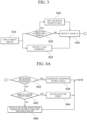
- FIG. 1 An electronic device 10 according to an exemplary embodiment of the present invention will be described with reference to FIG. 1 .
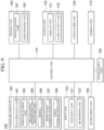
- FIG. 1 is a block diagram of an electronic device 10 according to an exemplary embodiment of the present invention.
- the electronic device 10 may include an image input unit 12, an area setting unit 14, a vehicle detecting unit 16, and a vehicle tracking unit 18.
- the image input unit 12 receives an image captured while a vehicle is driving.
- the image input unit 12 may receive a front image directly captured by a camera module included in the electronic device 10. Alternatively, an image related to driving of the vehicle may be directly received from at least one external camera (not shown). For example, when the electronic device 10 operates as a vehicle navigation device, the image input unit 12 may receive an image captured by a video recorder device of the vehicle.
- the image acquired by the image input unit 12 may be a video which is continuously captured. That is, front images may be received at a predetermined ratio of frames per second.
- the frame rate for receiving the front images may be changed according to various conditions such as a speed of the vehicle, weather of a surrounding environment, and the like.
- the area setting unit 14 sets a search area of the vehicle in a target image based on the location of the vehicle or the vehicle area detected from the previous image among the front images.
- the area setting unit 14 previously sets an area in which the vehicle is expected to exist so that the vehicle detecting unit 16 may detect the vehicle in the set area, instead of searching for the vehicle in the entire input front image (to be described later) .
- the area setting unit 14 may use information of the vehicle detected from the previous image.
- the forward vehicle may still be included in a predetermined area based on the position present in the previous image.
- the area setting unit 14 may set a candidate area for detecting the vehicle of the next image based on the location of the vehicle detected from the previous image.
- the candidate area may also be set using the detected area of the vehicle.
- a size of the forward vehicle may be determined through the detected area of the vehicle, and the search area may be set by extending a width and a height based on the size of the vehicle.
- the vehicle detecting unit 16 detects the vehicle in the set search area according to a machine learning model.
- the vehicle may be detected by a method of learning a Haar algorithm as a method of generating an adaptive detection area in order to increase a processing rate of vehicle detection, and after the detection, the detected area of the vehicle may be expanded and used as a detection area of a next image.
- the Haar algorithm which is based on a theory that a specific feature has a difference between light and shade
- used as the learning method is a method of finding a feature using a difference in brightness between areas in an image
- a characteristic brightness difference of the vehicle may be learned, based on which a feature may be located to detect the forward vehicle.
- the algorithm used for learning to detect the forward vehicle various image processing methods other than the Haar algorithm may be used. For example, histogram of oriented gradient (HOG) and local bit pattern (LBP) feature point extracting methods may be used. In addition, Adaboost and support vector machine (SVM) algorithm may be applied as the learning algorithm.
- HOG histogram of oriented gradient
- LBP local bit pattern
- SVM support vector machine
- vehicle detection may be continuously performed ceaselessly through feature point-based vehicle tracking in case of non-detection in order to compensate for a problem that may occur when the vehicle tracking is performed only by the detection based on the machine learning.
- the vehicle tracking unit 18 may extract a feature point from the previous front image or the vehicle area of the previous front image and track the vehicle area using an optical flow.
- the vehicle detecting unit 16 may continue to detect the vehicle based on the machine learning simultaneously when the vehicle tracking unit 18 tracks the vehicle area.
- the tracking process of the vehicle tracking unit 18 is stopped when the vehicle detecting unit successfully detects the vehicle, an adaptive search area is set with the detected vehicle area, and vehicle detection is continued.
- the vehicle tracking unit 18 may track movement of the forward vehicle using the optical flow.
- FIG. 2 is a flowchart illustrating a vehicle detecting method according to the present exemplary embodiment.
- the image input unit receives continuously captured front images (S10).
- the image input unit 12 receives the front images captured through the camera module according to a determined frame rate.
- the front images captured at a rate of 30 frames per second may be continuously received, and if a frame rate for receiving the images is set, the captured front images may be received according to the set frame rate.
- the area setting unit 14 sets a search area of the vehicle in a target image based on a location of the vehicle or a vehicle area detected in a previous image among the continuously input front images (S20).
- the previous image may be at least one image of the input front images and may include a plurality of images as well as a single image.
- the target image may be an image which is a target of extraction of an object among the input front images.
- the area setting unit 14 may set the search area based on the location of the vehicle or the area recognized as the vehicle, and apply the set search area to the target image.
- the area setting unit 14 may first determine whether an adaptive search area exists (S22).
- the area setting unit 14 may adaptively expand the search area according to information of the vehicle detected in the previous front image to generate a search area and set the generated search area to an area in which the vehicle is to be searched from a next target front image.
- the search area may be set to an area for detecting the vehicle (S24).
- the vehicle detecting unit 16 detects the vehicle from the search area according to the machine learning model (S30).
- the vehicle in the detecting of the vehicle (S30), the vehicle is detected from the search area of the front image.
- Image information of the forward vehicle may be searched according to the machine learning model, an object corresponding thereto may be detected, and the object may be recognized as the forward vehicle.
- the candidate area when setting a candidate area for detecting the vehicle, the candidate area may be set using a detected lane marking (S23) . That is, in the present exemplary embodiment, when setting the candidate area for detecting the vehicle in the front image, the vehicle may be efficiently and rapidly detected by setting a driving lane based on a lane marking detected as a range of the area as a detection target area.
- S23 detected lane marking
- the lane marking may be defined in a simple, uniform shape compared to the vehicle, the lane may be more easily detected from the image and the vehicle detecting unit 16 may also detect the vehicle using the detected lane marking (S30).
- the vehicle detected in the present exemplary embodiment may be a forward vehicle as a target
- the lane marking may be used such that the vehicle in the traffic lane in which the vehicle is currently driving may be detected as the forward vehicle.
- the area setting unit 14 may determine the setting of the search area into the driving lane.
- the adaptive search area may be adaptively enlarged and set in consideration of a size of the vehicle, and thus may be used to consider a ratio of the vehicle to the lane to determine the size of the vehicle.
- a width of the lane may be standardized and determined according to a standard of a general road in advance, a type of the vehicle may be determined based on the ratio of the width of the vehicle to the determined width of the lane and may be used for setting the search area.
- the vehicle detecting unit 16 may detect the vehicle according to the machine learning model from the front image without setting the search area (S30).
- the forward vehicle may be detected using the entire front image.
- the search area may be partially limited by using the information of the lane marking in the front image and may be used to first detect the forward vehicle.
- a road area may be recognized based on a vanishing point of the front image, and the forward vehicle may be detected in the area.
- a background area and a road area may be distinguished from the entire image, and for the road area, a traffic lane in which the vehicle drives may be first detected and then an object located in a traffic lane may be detected as a forward vehicle.
- the vehicle detecting unit 16 may determine whether the vehicle is detected.
- vehicle detection may continue through vehicle tracking if a forward vehicle is not detected.
- the detection of the forward vehicle may be performed as an auxiliary function for safe driving, such as a front collision situation. If detection of a forward vehicle, which actually exists, fails so it is erroneously recognized that the forward vehicle is not present, erroneous operation information may be provided to the user. Therefore, the present exemplary embodiment proposes a method of additionally performing vehicle detection if a vehicle is not detected according to the machine learning model.
- a search area may be adaptively generated through information of the detected vehicle (S34).
- the vehicle tracking unit 18 continues to track the vehicle using vehicle feature points.
- the vehicle tracking unit 18 first determines whether there is a feature point from the previously extracted image of the vehicle (S42).
- the feature point may be an area including one pixel or a plurality of pixels of an optically characterized image.
- the feature point may be set to a value which is changed less in the vehicle area of the continuously input front images.
- the vehicle tracking unit 18 may set an area which is distinguished from other peripheral objects and which has a feature value changed less in the vehicle area.
- the vehicle area may be tracked using an optical flow of the feature point (S44).
- a feature point is extracted in an adaptive search area of the previous front image (S46) and the feature point extracted from the previous image is tracked according to an optical flow in a subsequently input front image to recognize a vehicle (S44).
- the process of detecting or tracking the vehicle described above may be repeatedly performed according to a continuous input of the front image (S10).
- the vehicle tracking unit 18 may determine when vehicle detection fails by comparing the detected reliability of the vehicle with a reference value. That is, even if the vehicle is detected by the machine learning model, when the reliability is low compared to the previous image of the vehicle, the vehicle may be tracked using the feature point.
- the reliability is used as a reference for determining whether the vehicle tracking unit 18 performs vehicle tracking, and the vehicle tracking unit 18 may determine whether to perform vehicle tracking by determining whether an object detected by the vehicle detecting unit 16 from the image is a vehicle.
- the object in the image detected by the vehicle detecting unit 16 may be compared with a predetermined vehicle criterion (e.g., size, shape, color or a conformity degree to an object in the previous image, etc.) to determine that the object is a forward vehicle, and a degree to which the object matches the criteria may be determined as reliability of the recognized object. Therefore, when the reliability of the detected object is less than 50%, for example, the vehicle tracking unit 18 may determine that the vehicle detection fails, and perform vehicle tracking.
- a predetermined vehicle criterion e.g., size, shape, color or a conformity degree to an object in the previous image, etc.
- the vehicle detecting unit 16 may directly determine the reliability of the detected object in the image. Therefore, the vehicle detecting unit 16 may determine the reliability of the detected object with respect to the vehicle, and if the reliability is lower than the reference, the vehicle detecting unit 16 may deliver a result of determination that the vehicle detection fails to the vehicle tracking unit 18 so that vehicle tracking may be performed by the vehicle tracking unit 18.
- vehicle detection based on the machine learning model (S30) is continuously performed.
- performing of vehicle detection based on the machine learning model is basically set, and vehicle tracking based on an optical flow may be additionally performed to recognize movement of the forward vehicle continuously even when vehicle detection based on the machine learning model fails.
- vehicle tracking based on the optical flow may be additionally performed, and if vehicle detection again based on the machine learning model is successful, the vehicle tracking based on the optical flow may be stopped and only the vehicle detection operation based on the machine learning model may be performed.
- a tracking result of the vehicle may be further used.
- the detecting of the vehicle (S30) may use the information of the feature point determined in the process of tracking the vehicle when the adaptive search area is set to increase a success rate of the vehicle detection.
- a motion vector of the feature point of the vehicle is obtained from a plurality of previous images.
- the area setting unit 14 calculates an optical flow as a motion vector and reflect the motion vector in the adaptive search area generated in the previous image.
- a modified search area is generated based on the motion vector and the search area. Specifically, an expansion value of the search area may be determined according to a size and direction of the motion vector and a modified search area may be generated.
- vehicle detection may be performed in the modified search area based on the machine learning model and a detection probability of the vehicle may be further increased.
- a classifier separately trained according to a size of the vehicle or a characteristic of a distance to the forward vehicle may also be used.
- classifiers generated after classifying databases storing images of the vehicle into a general passenger vehicle and a large vehicle and learning the same may be used.
- a classifier which has trained only an image of a tail light side, rather than the entire vehicle image, may also be used.
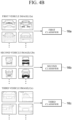
- three classifiers may be trained.
- a first classifier 16a may be trained using a first vehicle image 12a.
- the first vehicle image 12a is an image of a general passenger vehicle
- the first classifier 16a may perform the machine learning using the image of the general passenger vehicle and improve classification performance for the general passenger vehicle.
- a second classifier 16b may be trained using a second vehicle image 12b.
- the second vehicle image 12b may be a rear image of a vehicle such as a bus or a truck as a large vehicle.
- the second classifier 16b trained with the second vehicle image 12b may have high classification performance for a large vehicle.
- a third classifier 16c may be separately trained in consideration of a feature based on a distance to a forward vehicle, not the size of the vehicle.
- a third vehicle image 12c obtained for a vehicle located very nearby may include only information on a partial area, rather than the entire image of the vehicle such as the first vehicle image 12a and the second vehicle image 12b.
- the third classifier 16c may be trained using the separate image including only the partial area as a learning image.
- the vehicle may be detected more accurately using the classifiers individually trained according to the image features based on the size of each vehicle or the distance to the forward vehicle.
- a plurality of individually classified classifiers may be sequentially used.
- a detection result is checked (S1010) and if a first vehicle is classified by the first classifier trained according to the first vehicle image, the detecting of the vehicle (S30) may be terminated because the detection is successful (S5000).
- detection based on the second classifier may be performed (S2000).
- a detection result is checked (S2010) and if a second vehicle is detected by the second classifier trained according to the second vehicle image, the detecting of the vehicle (S30) may be terminated because the detection is successful (S5000). However, if the second vehicle is not detected even by the second classifier, detection may be performed by the third classifier (S3000).
- the detecting of the third vehicle located nearby (S3010) may be terminated because the detection is successful (S5000) .
- a process of tracking a vehicle based on a feature point may be performed in the tracking of the vehicle (S40).
- the detection process according to each classifier is sequentially performed, but when parallel processing is possible, inputting to the classifier may be performed at the same time and the classification results may be collected to generate an optimal detection result.
- the third classifier In the case of a vehicle close nearby such as the third classifier, it is necessary to preferentially detect the vehicle according to safety requirements, so that the detection based on the third classifier may be performed with priority.
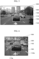
- FIG. 5 is a diagram illustrating an example of detecting a vehicle from an input front image 1000 according to an exemplary embodiment.
- the vehicle detecting unit 16 may detect a vehicle 1200 from an input front image 1000.
- the vehicle is detected from an adaptive search area, but as described above, if there is no search area generated as the first front image, the vehicle may be detected from the entire front image.
- the adaptive search area is not set, so that the object determined as the forward vehicle may be detected in the entire image.
- the vehicle detecting unit 16 may more easily detect the forward vehicle using lane information 1105 in a road as described above.
- the vehicle detecting unit 16 may calculate width w and height h information of an object 1200 determined as the vehicle.
- the area setting unit 14 may set the adaptive search area using the calculated width and height.
- the area setting unit may expand a search area according to height and width values of the vehicle in an area 1100 in which the vehicle 1200 is determined to exist in a previous image to adaptively generate a search area 1300 in the front image.
- the area expanded in four directions by half (w/2) of the width and half (h/2) of the height is set as the adaptive search area.
- the area setting unit 14 may set the adaptive search area on the assumption that the vehicle will be located in the expanded adaptive search area unless there is a sudden change in the speed of the vehicle in the continuously input image in consideration of a frame rate.
- an image received in the image input unit 12 is 30 frames per second, it is included in an area range of a previous image unless movement of the forward vehicle is very large.
- a search area enlarged according to the detected vehicle width or height is set, and this area is designated as a search area for vehicle detection in a next successive image. If this process is repeatedly performed, the search area is adaptively changed according to the size or location of the detected vehicle.
- the adaptive search area set in the present exemplary embodiment is based on the size of the vehicle, but the size may be determined using a frame rate of the input image, and in addition, the information such as the speed of the vehicle, a driving direction of the vehicle, and the like may also be additionally considered.
- the adaptive search area may be further enlarged, and the search area may be enlarged even when the vehicle is making a curve.
- a vehicle in a next lane may be recognized as a forward vehicle. Therefore, it is also possible to accurately recognize the vehicle located in the current driving lane as a forward vehicle by utilizing a lane detection result together with the adaptive search area.
- the vehicle detecting unit 16 may detect the vehicle in a partial area of the input front image 1000.
- the candidate area 1300 in which a forward vehicle is expected to exist is set and vehicle detection is performed only in the set range according to the machine learning model in FIG. 7 , the forward vehicle may be more rapidly and accurately detected.
- a feature point is extracted from a previous vehicle area and a vehicle area is tracked using an optical flow, and at the same time, vehicle detection based on the machine learning is also performed.
- a vehicle is detected by continuously setting an adaptive search area according to the machine learning model, and when a vehicle is not detected from a front image, a process of tracking a vehicle through feature point extraction may be simultaneously performed (82).
- an electronic device 10 may be implemented as one module of an advanced driver assistance system (ADAS) or a system 100 for autonomous driving to perform route guide and forward vehicle collision warning system (FVCWS). This will be described in more detail with reference to FIGS. 9 and 10 .
- ADAS advanced driver assistance system
- FVCWS route guide and forward vehicle collision warning system
- FIG. 9 is a block diagram illustrating a system according to an exemplary embodiment of the present invention.
- the system 100 includes all or some of a storage unit 110, an input unit 120, an output unit 130, a curve guide unit 140, an augmented reality (AR) providing unit 160, a controller 170, a communication unit 180, a sensing unit 190, and a power supply unit 195.
- AR augmented reality
- the system 100 may be implemented by various devices such as a smartphone, a tablet computer, a laptop computer, a personal digital assistant (PDA), a portable multimedia player (PMP), smart glasses, project glasses, navigation which may provide driving-related guide to a driver of a vehicle, a digital video recorder, a car dash cam, or a car video recorder which are imaging devices for vehicle, and the like, and may be provided in a vehicle.
- devices such as a smartphone, a tablet computer, a laptop computer, a personal digital assistant (PDA), a portable multimedia player (PMP), smart glasses, project glasses, navigation which may provide driving-related guide to a driver of a vehicle, a digital video recorder, a car dash cam, or a car video recorder which are imaging devices for vehicle, and the like, and may be provided in a vehicle.
- PDA personal digital assistant
- PMP portable multimedia player
- smart glasses project glasses
- navigation which may provide driving-related guide to a driver of a vehicle
- a digital video recorder
- Driving-related guide may include various guide for assisting a driver in driving a vehicle such as route guide, lane departure guide, lane keeping guide, forward vehicle departure guide, traffic light change guide, forward vehicle collision warning guide, traffic lane change guide, traffic lane guide, curve guide, and the like.
- the route guide may include augmented reality (AR) route guide to perform route guide by combining various information such as a position, a direction, and the like of the user to a captured image of a front side of a vehicle in operation and 2-dimensional (2D) or 3-dimensional (3D) route guide to perform route guide by combining various information such as the user's location, direction, and the like to 2D or 3D map data.
- AR augmented reality
- 3D 3-dimensional
- the route guide may include an aerial map route guide to perform route guide by combining various information such as a user's location, direction, and the like to aerial map data.
- the route guide may be interpreted as a concept including not only the route guide of a case where the user gets in a vehicle to drive the vehicle but also a route guide of a case where the user walks or runs to move.
- the lane departure guide may guide/notify a driving vehicle of whether or not the driving vehicle is out of a lane.
- the lane keeping guide may guide the vehicle to return to the lane in which the vehicle is originally driving.
- the forward vehicle departure guide may guide departure of a vehicle located in front of a vehicle being stopped.
- the traffic light change guide may guide/notify the vehicle of whether or not a signal of a traffic light located in front of the vehicle being stopped is changed.
- the traffic light change guide may guide a change in a traffic light from a red traffic light indicating a stop signal to a blue traffic light indicating a start signal.
- the forward vehicle collision warning guide may guide that a distance to a vehicle located in front of a vehicle being stopped or driving is within a certain distance to prevent a collision with the forward vehicle.
- the distance between the forward vehicle and the current vehicle is calculated through the machine learning model or feature point extraction and a collision prevention guide may be provided accordingly.
- the traffic lane change guide may guide a vehicle from a traffic lane in which the vehicle is located to another traffic lane to guide a route to a destination.
- the traffic lane guide may guide the vehicle in a traffic lane in which the current vehicle is located.
- the curve guide may guide/notify the vehicle that a road on which the vehicle will drive after a predetermined time is a curve.
- a driving-related image such as a front image of a vehicle that enables provision of various guide, may be captured by a camera mounted in a vehicle or a camera of a smartphone.
- the camera may be a camera formed integrally with the system 100 mounted in the vehicle and imaging the front of the vehicle.
- the camera may be a camera mounted in the vehicle separately from the system 100 to image the front of the vehicle.
- the camera may be a separate vehicle image capturing device mounted toward the front of the vehicle, and the system 100 may receive a captured image through wired/wireless communication with the vehicle image capturing device mounted separately or receive a captured image of the vehicle image capturing device when a storage medium storing the captured image is inserted into the system 100.
- the storage unit 110 functions to store various data and applications required for the operation of the system 100.
- the storage unit 110 may store data necessary for the operation of the system 100, for example, an OS, a route search application, map data, and the like.
- the storage unit 110 may store data generated by the operation of the system 100, for example, searched route data, a received image, and the like.
- the storage unit 110 may be implemented as an internal storage such as a random access memory (RAM), a flash memory, a read only memory (ROM), erasable programmable ROM (EPROM), electronically erasable and programmable ROM (EEPROM), a register, a hard disk, a removable disk, a memory card, a universal subscriber identity module (USIM), or the like, as well as a removable storage such as a USB memory.
- RAM random access memory
- ROM read only memory
- EPROM erasable programmable ROM
- EEPROM electronically erasable and programmable ROM
- the input unit 120 functions to convert a physical input from the outside of the system 100 into a specific electrical signal.
- the input unit 120 may include all or some of a user input unit 121 and a microphone unit 123.
- the user input unit 121 may receive a user input such as a touch or a push operation.
- the user input unit 121 may be implemented using at least one of various types of buttons, a touch sensor receiving a touch input, and a proximity sensor receiving an approaching motion.
- the microphone unit 123 may receive a user's voice and sound generated in and outside the vehicle.
- An output unit 130 is a unit for outputting data of the system 100 to the user, as image and/or sound.
- the output unit 130 may include all or some of a display unit 131 and an audio output unit 133.
- the display unit 131 is a unit for outputting data which may be visually recognized by the user.
- the display unit 131 may be implemented as a display unit provided on a front surface of a housing of the system 100.
- the display unit 131 may be formed integrally with the system 100 to output visual recognition data or may be installed separately from the system 100, such as a head up display (HUD), to output visual recognition data.
- HUD head up display
- the audio output unit 133 is a unit for outputting data that may be recognized acoustically by the system 100.
- the audio output unit 133 may be implemented as a speaker that expresses data of the system 100 to be reported to the user, as a sound.
- a curve guide unit 140 may perform a function of the curve guidance, described above. Specifically, the curve guide unit 140 may obtain link information corresponding to a road on which the vehicle drives, determine a location of the vehicle at a link at a future time point, and determine a risk of a curve section in which the vehicle is to drive after a predetermined time using the determined location and a vehicle speed at a reference time point.
- the AR providing unit 160 may provide an AR view mode.
- AR refers to a method of providing additional information (e.g., a graphic element indicating a point of interest (POI), a graphic element guiding a curve, and various additional information for assisting a driver in driving safe, etc.) visually in an overlapping manner on a screen containing a real world that the user actually views.
- additional information e.g., a graphic element indicating a point of interest (POI), a graphic element guiding a curve, and various additional information for assisting a driver in driving safe, etc.
- the AR providing unit 160 may include all or some of a calibration unit, a 3D space generating unit, an object generating unit, and a mapping unit.
- the calibration unit may perform a calibration for estimating a camera parameter corresponding to the camera from an image captured by the camera.
- the camera parameter is a parameter constituting a camera matrix which is information indicating a relationship in which an actual image space is formed on a picture, and may include extrinsic parameters and intrinsic parameters.
- the 3D space generating unit may generate a virtual 3D space based on the image captured by the camera. Specifically, the 3D space generating unit may generate a virtual 3D space by applying a camera parameter estimated by the calibration unit to a 2D captured image.
- the object generating unit may generate an object for guiding in AR, for example, a route guide object, a front collision warning guide object, a traffic lane change guide object, a lane departure guide object, a curve guide object, and the like.
- the mapping unit may map an object generated by the object generating unit to a virtual 3D space generated by the 3D space generating unit. Specifically, the mapping unit may determine a position in the virtual 3D space of the object generated by the object generating unit and map the object to the determined position.
- the communication unit 180 may be provided for the system 100 to communicate with other devices.
- the communication unit 180 may include all or some of a location data unit 181, a wireless internet unit 183, a broadcast transceiver unit 185, a mobile communication unit 186, a short-range communication unit 187, and a wired communication unit 189.
- the location data unit 181 is a device for obtaining location data through a global navigation satellite system (GNSS) .
- GNSS refers to a navigation system that may calculate a location of a receiver terminal using radio signals received from satellites.
- Specific examples of GNSS include global positioning system (GPS), Galileo, global orbiting navigational satellite system (GLONASS), COMPASS, Indian regional navigational satellite system (IRNSS), quasi-zenith satellite system (QZSS), and the like depending on an operating subject.
- the location data unit 181 of the system 100 may obtain location data by receiving a GNSS signal provided in an area where the system 100 is used.
- the location data unit 181 may obtain location data through communication with a base station or an access point (AP) in addition to the GNSS.
- AP access point
- the wireless Internet unit 183 is a unit for accessing the wireless Internet to obtain or transmit data.
- the wireless Internet unit 183 may access the Internet through various communication protocols defined to perform wireless data transmission and reception of wireless LAN (WLAN), wireless broadband (Wibro), world interoperability for microwave access (Wimax), and high speed downlink packet access (HSDPA).
- WLAN wireless LAN
- Wibro wireless broadband
- Wimax world interoperability for microwave access
- HSDPA high speed downlink packet access
- the broadcast transceiver unit 185 is a unit for transmitting and receiving broadcast signals through various broadcast systems. Broadcast systems that may transmit and receive signals through the broadcast transceiver unit 185 include digital multimedia broadcasting terrestrial (DMBT), digital multimedia broadcasting satellite (DMBS), media forward link only (MediaFLO), digital video broadcast handheld (DVBH), integrated services digital broadcast terrestrial (ISDBT), and the like.
- DMBT digital multimedia broadcasting terrestrial
- DMBS digital multimedia broadcasting satellite
- MediaFLO media forward link only
- DVBH digital video broadcast handheld
- ISDBT integrated services digital broadcast terrestrial
- the broadcast signals transmitted and received through the broadcast transceiver unit 185 may include traffic data, living data, and the like.
- the mobile communication unit 186 may perform voice and data communication by accessing a mobile communication network according to various mobile communication standards such as 3rd generation (3G), 3rd generation partnership project (3GPP), long term evolution (LTE), and the like.
- 3G 3rd generation
- 3GPP 3rd generation partnership project
- LTE long term evolution
- the short-range communication unit 187 is a unit for near field communication. As described above, the short-range communication unit 187 may perform communication through Bluetooth, radio frequency identification (RFID), infrared data association (IrDA), ultra wideband (UWB), ZigBee, near field communication (NFC), and wireless-fidelity (Wi-Fi).
- RFID radio frequency identification
- IrDA infrared data association
- UWB ultra wideband
- ZigBee ultra wideband
- NFC near field communication
- Wi-Fi wireless-fidelity
- the wired communication unit 189 is an interface unit that may connect the system 100 to another device by wire.
- the wired communication unit 189 may be a USB module capable of communicating through a USB port.
- the communication unit 180 may communicate with another device using at least one of the location data unit 181, the wireless Internet unit 183, the broadcast transceiver unit 185, the mobile communication unit 186, the short-range communication unit 187, and the wired communication unit 189.
- an image captured by an image capture unit for a vehicle such as a digital video recorder, a car dash cam, or a car video recorder may be received using at least one of the short-range communication unit 187 and the wired communication unit 189.
- any one may communicate with the short-range communication unit 187, and the other may communicate with the wired communication unit 119.
- the sensing unit 190 is a unit that may detect a current state of the system 100.
- the sensing unit 190 may include all or some of a motion sensing unit 191 and a light sensing unit 193.
- the motion sensing unit 191 may detect a motion in a three-dimensional space of the system 100.
- the motion sensing unit 191 may include a 3-axis geomagnetic sensor and a 3-axis acceleration sensor. By combining motion data obtained through the motion sensing unit 191 with location data obtained through the location data unit 181, a trace of a vehicle to which the system 100 is attached may be more accurately calculated.
- the light sensing unit 193 is a unit for measuring ambient illuminance of the system 100. Using the illuminance data acquired through the light sensing unit 193, brightness of the display unit 131 may be changed to correspond to ambient brightness.
- the power supply unit 195 is a device for supplying power necessary for an operation of the system 100 or an operation of other devices connected to the system 100.
- the power supply unit 195 may be a battery built in the system 100 or a unit that receives power from an external power source such as the vehicle.
- the power supply unit 195 may be implemented as a wired communication unit 119 or a device that is wirelessly supplied according to a form of receiving power.
- the controller 170 controls an overall operation of the system 100. Specifically, the controller 170 may control all or some of the storage unit 110, the input unit 120, the output unit 130, the curve guide unit 140, the AR providing unit 160, the communication unit 180, the sensing unit 190, and the power supply unit 195.
- the controller 170 may acquire link information corresponding to a road on which the vehicle will drive.
- the link information may be obtained from route guide data for route guide to a destination.
- the controller 170 may generate route guide data to a destination using map data previously stored in the storage unit 110.
- the controller 170 may transmit a route guide request including at least one of current location information and destination information to the server.
- the controller 170 may receive route guide data from the server according to the route guide request. In this case, the controller 170 may obtain link information corresponding to a road on which the vehicle drives from the route guide data.
- the controller 170 may obtain link information based on the generated information.
- the controller 170 may calculate the relative speed of the forward vehicle in consideration of a change of the distance to the vehicle in the input front image and a frame rate and generate front collision warning guide information by comparing the relative speed of the forward vehicle with the speed of the current vehicle.
- the controller 170 may control the output unit 130 to output necessary deceleration information according to a determination result. In addition, the controller 170 may calculate acceleration information necessary for specific deceleration.
- a req t A TV + V r t 2 2 * x c t ⁇ x r t
- the distance to the forward vehicle may be calculated by further considering a driving distance X r (t) for a time required for the driver to react to control a brake for deceleration.
- the controller 170 may control the output unit 130 to output a second deceleration guide.
- the second level may be a numerical value indicating that the user needs a higher degree of deceleration.
- the controller 170 may control the output unit 130 not to output a deceleration guide.
- the deceleration guide may be performed in an AR screen.
- the AR providing unit 160 may generate a forward vehicle collision warning guide object and map the generated forward vehicle collision warning guide object to a virtual 3D space to generate an AR screen and the controller 170 may control the display unit 131 to display the generated AR screen.
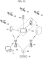
- FIG. 10 is a diagram illustrating a system network connected to a system according to an exemplary embodiment of the present invention.
- the system 100 may be implemented by various devices provided in a vehicle such as a navigation device, a vehicle imaging device, a smartphone, or a device providing an AR interface for a vehicle and may be connected to various communication networks and other electronic devices 61 to 64.
- system 100 may calculate a current location and a current time zone by interworking with a GPS module according to a radio wave signal received from a satellite 20.
- Each satellite 20 may transmit L-band frequencies having different frequency bands.
- the system 100 may calculate a current location based on a time taken for the L band frequency transmitted from each satellite 20 to reach the system 100.
- the system 100 may be wirelessly connected to a network 30 through a controller station (ACR) 40, a base station (RAS) 50, an access point (AP), or the like via the communication unit 180.
- ACR controller station
- RAS base station
- AP access point
- the system 100 may also be indirectly connected to other electronic devices 61 and 62 connected to the network 30 to exchange data.
- the system 100 may be indirectly connected to the network 30 through another device 63 having a communication function.
- the system 100 may communicate with another device 63 having a communication function through a short-range communication module or the like.
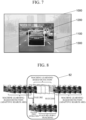
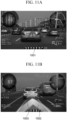
- FIGS. 11A and 11B are views illustrating a forward vehicle collision warning screen of a system according to an exemplary embodiment of the present invention.
- the system 100 may generate a guide object indicating a risk of forward vehicle collision and output the generated guide object 1001 or 1003 through AR.
- system 100 may output the guide objects 1001 and 1003 through voice.
- system 100 may output the guide objects 1001 and 1003 through a haptic element.
- the system 100 for a vehicle may include a display unit 131 provided on the front of the housing, a user input unit 121, and a microphone unit 123.
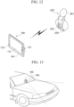
- FIG. 13 is a diagram illustrating an implementation form when a system according to an exemplary embodiment of the present invention having an image capture unit.
- the system 100 when the system 100 includes an image capture unit 150, the image capture unit 150 may capture an image of the front of the vehicle and a display part of the system 100 may be recognized by the user. Accordingly, the system according to an exemplary embodiment of the present invention may be implemented.
- FIG. 14 is a diagram illustrating an implementation form using a head-up display (HUD) according to an exemplary embodiment of the present invention.
- the HUD may display an AR guide screen on the HUD through wired/wireless communication with other devices.
- the AR may be provided through image overlay using the HUD using a vehicle windshield or a separate image output device, and the AR providing unit 160 may generate an interface image overlaid on a reality image or glass as described above. Accordingly, AR navigation or vehicle infotainment system may be implemented.
- the forward vehicle collision warning guide method may be implemented as a program and provided to a server or devices. Accordingly, each device may access the server or device where the program is stored, to download the program.
- a forward vehicle detecting method or a forward vehicle collision warning guide method may be configured by a module in a control device 2100 of an autonomous vehicle 2000. That is, a memory 2122 and a processor 2124 of the control device 2100 may implement the forward vehicle detecting method or the forward vehicle collision warning guide method in software.
- the autonomous vehicle 2000 may include a control device 2100, sensing modules 2004a, 2004b, 2004c, and 2004d, an engine 2006, and a user interface 2008.
- the controller 2120 may deliver a control signal to the sensor 2110, the engine 2006, the user interface 2008, the wireless communication device 2130, the LiDAR 2140, and the camera module 2150 included as other components in the vehicle.
- the control signal may also be transmitted to an acceleration device, a braking system, a steering device, or a navigation device related to driving of the vehicle.
- the controller 2120 may control the engine 2006 or the braking system to decelerate the driving vehicle and control a trace, a driving route, and a steering angle in addition to the speed.
- the controller 2120 may control the driving of the vehicle by generating a necessary control signal according to recognition information of a driving lane, a driving signal, or other external environment of the vehicle.
- the controller 2120 may control the driving of the vehicle by performing communication with a nearby vehicle or a central server and transmitting a command for controlling peripheral devices through received information.
- the controller may generate a control signal to control the camera module 2150 to perform calibration. Therefore, in the present exemplary embodiment, since the controller 2120 generates the calibration control signal to the camera module 2150, even if a mounting position of the camera module 2150 is changed due to vibration or shock generated due to movement of the autonomous vehicle 2000, a normal mounting position, direction, angle of view, and the like of the camera module 2150 may be continuously maintained.
- the controller 2120 may generate the control signal for the camera module 2150 to perform calibration if previously stored initial mounting position, direction, angle of view information of the camera module 2150 and an initial mounting position, direction, angle of view information, and the like of the camera module 2150 measured while the autonomous vehicle 2000 is driving are different by a threshold value or greater.
- the memory 2122 may store at least an operating system (OS), a user application, and executable instructions.
- OS operating system
- the memory 2122 may also store application data and array data structures.
- the processor 2124 may be implemented by combining computing devices, and the computing devices may include a digital signal processor, a microprocessor or an appropriate combination thereof.
- the sensor 2110 may include at least one sensing module 2004, and the sensing module 2004 may be implemented at a specific position of the autonomous vehicle 2000 according to a sensing purpose.
- the sensing module 2004 may be located at the lower, rear, front, top, or side ends of the autonomous vehicle 2000 and may also be located at an internal component or a tire of the vehicle.
- the sensing module 2004 may detect information related to driving such as the engine 2006, a tire, a steering angle, a speed, a weight of the vehicle, and the like as the internal information of the vehicle.
- the at least one sensing module 2004 may include an acceleration sensor 2110, a gyroscope, an image sensor 2110, a RADAR, an ultrasonic sensor, a LiDAR sensor, and the like and detect movement information of the autonomous vehicle 2000.
- the senor 2110 may integratedly collect information of the sensing modules 2004 for collecting information generated inside and outside the autonomous vehicle 2000.
- the control device 2100 may further include a wireless communication device 2130.
- the wireless communication device 2130 is configured to implement wireless communication between the autonomous vehicles 2000.
- the autonomous vehicle 2000 may communicate with a user' s mobile phone or another wireless communication device 2130, another vehicle, a central device (traffic control device), a server, and the like.
- the wireless communication device 2130 may transmit and receive a wireless signal according to an access wireless protocol.
- a wireless communication protocol may be Wi-Fi, Bluetooth, long-term evolution (LTE), code division multiple access (CDMA), wideband code division multiple access (WCDMA), global systems for mobile communications (GSM) but is not limited thereto
- the autonomous vehicle 2000 may implement inter-vehicle communication through the wireless communication device 2130. That is, the wireless communication device 2130 may communicate with other vehicles on the road through vehicle-to-vehicle communication.
- the autonomous vehicle 2000 may transmit and receive information such as a driving warning and traffic information through vehicle-to-vehicle communication and may request information or receive a request from another vehicle.
- the wireless communication device 2130 may perform V2V communication as a dedicated short-range communication (DSRC) device or a cellular-V2V (C-V2V) device.
- DSRC dedicated short-range communication
- C-V2V cellular-V2V
- control device 2100 may include a LiDAR device 2140.
- the LiDAR device 2140 may detect an object around the autonomous vehicle 2000 during an operation using data sensed by the LiDAR sensor.
- the LiDAR device 2140 may transmit the detected information to the controller 2120, and the controller 2120 may operate the autonomous vehicle 2000 according to the detection information.
- the controller 2120 may instruct the vehicle to reduce a speed through the engine 2006 if there is a forward vehicle driving at a low speed in the detection information.
- the controller may instruct the vehicle to reduce an entry speed according to a curvature of a curve to which the vehicle moves.
- control device 2100 may further include imaging devices for recognizing an external environment.
- imaging devices for recognizing an external environment.
- a RADAR a GPS device
- driving distance measuring device odometry
- other computer vision devices may be used, and these devices may be selectively or simultaneously operated as needed to allow more precise sensing.
- the autonomous vehicle 2000 may further include the user interface 2008 for user input for the control device 2100 described above.
- the user interface 2008 may allow the user to input information through appropriate interactions.
- the user interface 2008 may be implemented as a touch screen, a keypad, an operation button, or the like.
- the user interface 2008 may transmit an input or a command to the controller 2120, and the controller 2120 may perform a control operation of the vehicle in response to the input or the command.
- the user interface 2008 may allow a device outside the autonomous vehicle 2000 to communicate with the autonomous vehicle 2000 through the wireless communication device 2130.
- the user interface 2008 may interwork with a mobile phone, tablet, or other computer devices.
- the autonomous vehicle 2000 has been described as including an engine 2006, but it may also include other types of propulsion systems.
- the vehicle may be driven by electrical energy and may be driven through hydrogen energy or a hybrid system as a combination thereof.
- the controller 2120 may include a propulsion mechanism according to the propulsion system of the autonomous vehicle 2000 and provide corresponding control signals to components of each propulsion mechanism.
- control device 2100 for performing the forward vehicle detecting method or the forward vehicle collision warning guide method according to the present invention with reference to FIG. 16 will be described in more detail.
- the control device 2100 includes the processor 2124.
- the processor 2124 may be a general-purpose single or multi-chip microprocessor, dedicated microprocessor, microcontroller, programmable gate array, or the like.
- the processor may be referred to as a central processing unit (CPU).
- the processor 2124 may be used as a combination of a plurality of processors.
- Data and instructions 2122a for performing the forward vehicle detecting method or the forward vehicle collision warning guide method according to the present invention may be stored in the memory 2122.
- the processor 2124 executes the instructions 2122a, all or part of the instructions 2122a and the data 2122b required for the execution of the instructions may be loaded 2124a and 2124b onto the processor 2124.
- the control device 2100 may include a communication interface 2180.
- the communication interface 2180 may include one or more ports and/or communication modules for connecting other devices to the control device 2100.
- the communication interface 2180 may allow the user and the control device 2100 to interact with each other.
- Various components of the control device 2100 may be connected together by one or more buses 2190, and the buses 2190 may include a power bus, a control signal bus, a status signal bus, a data bus, and the like.
- the components may transmit information to each other via the bus 2190 and perform a desired function under the control of the processor 2124.
- the device described herein may be implemented using hardware components, software components, or a combination thereof.
- the hardware components may include microphones, amplifiers, band-pass filters, audio to digital converters, and processing devices.
- a processing device may be implemented using one or more general-purpose or special purpose computers, such as, for example, a processor, a controller and an arithmetic logic unit (ALU), a digital signal processor, a microcomputer, a field programmable array (FPGA), a programmable logic unit (PLU), a microprocessor or any other device capable of responding to and executing instructions in a defined manner.
- ALU arithmetic logic unit
- FPGA field programmable array
- PLU programmable logic unit
- the software may include a computer program, a piece of code, an instruction, or some combination thereof, to independently or collectively instruct or configure the processing device to operate as desired.
- Software and data may be embodied permanently or temporarily in any type of machine, component, physical or virtual equipment, computer storage medium or device, or in a propagated signal wave capable of providing instructions or data to or being interpreted by the processing device.
- the software also may be distributed over network coupled computer systems so that the software is stored and executed in a distributed fashion.
- the software and data may be stored by one or more non-transitory computer readable recording mediums.
- the methods according to the above-described exemplary embodiments may be recorded in non-transitory computer-readable media including program instructions to implement various operations embodied by a computer.
- the media may also include, alone or in combination with the program instructions, data files, data structures, and the like.
- the program instructions recorded on the media may be those specially designed and constructed for the purposes of the exemplary embodiments, or they may be of the kind well-known and available to those having skill in the computer software arts.
- non-transitory computer-readable media examples include magnetic media such as hard disks, floppy disks, and magnetic tape; optical media such as CD ROM disks and DVDs; magneto-optical media such as floptical discs; and hardware devices that are specially configured to store and perform program instructions, such as read-only memory (ROM), random access memory (RAM), flash memory, and the like.
- program instructions include both machine codes, such as those produced by a compiler, and files containing higher level codes that may be executed by the computer using an interpreter.
- the described hardware devices may be configured to act as one or more software modules in order to perform the operations of the above-described exemplary embodiments, or vice versa.
Landscapes
- Engineering & Computer Science (AREA)
- Theoretical Computer Science (AREA)
- General Physics & Mathematics (AREA)
- Physics & Mathematics (AREA)
- Multimedia (AREA)
- Computer Vision & Pattern Recognition (AREA)
- Mechanical Engineering (AREA)
- Human Computer Interaction (AREA)
- Quality & Reliability (AREA)
- Computing Systems (AREA)
- Software Systems (AREA)
- Medical Informatics (AREA)
- General Health & Medical Sciences (AREA)
- Evolutionary Computation (AREA)
- Databases & Information Systems (AREA)
- Health & Medical Sciences (AREA)
- Artificial Intelligence (AREA)
- Traffic Control Systems (AREA)
- Image Analysis (AREA)
Claims (12)
- Verfahren zum Detektieren eines Fahrzeugs (1200), wobei das Verfahren umfasst:a) Empfangen (S10) von Bildern, die kontinuierlich von einer nach vorne gerichteten Kamera (150) aufgenommen werden;b) Einstellen eines Suchbereichs des Fahrzeugs in einem Zielbild basierend auf einem Ort des Fahrzeugs, der in einem vorherigen Bild unter den kontinuierlich aufgenommenen Bildern detektiert wird;c) Detektieren (S30) des Fahrzeugs in dem Suchbereich unter Verwendung eines Maschinenlernmodells; undd) wenn die Fahrzeugdetektion unter Verwendung des Maschinenlernmodells fehlschlägt das Fahrzeug zu erkennen, Fortsetzen der Fahrzeugdetektion durch Verfolgen (S40) des Fahrzeugs unter Verwendung eines Merkmalspunkts des Fahrzeugs, wobei der Merkmalspunkt aus dem Suchbereich des vorherigen Bilds extrahiert wird; unde) Verfolgen des Merkmalspunkts, der aus dem Suchbereich des vorherigen Bilds extrahiert wurde, unter Verwendung eines optischen Flusses in dem Zielbild, um ein Fahrzeug zu erkennen;f) wobei das Detektieren (S30) ferner ein Ermitteln eines Bewegungsvektors der Merkmalspunkte des Fahrzeugs aus einer Vielzahl von vorherigen Bildern und ein Erzeugen eines modifizierten Suchbereichs basierend auf den Bewegungsvektoren und dem Suchbereich umfasst, und ein Detektieren des Fahrzeugs aus dem modifizierten Suchbereich gemäß dem Maschinenlernmodell umfasst.
- Verfahren nach Anspruch 1, wobei der Suchbereich basierend auf dem aus dem vorherigen Bild detektierten Fahrzeugbereich vergrößert und eingestellt wird.
- Verfahren nach einem der vorhergehenden Ansprüche, wobei der Ort des Fahrzeugs aus dem Zielbild unter Verwendung der extrahierten Merkmalspunkte des Fahrzeugs verfolgt wird, wenn die Fahrzeugdetektion basierend auf dem Maschinenlernmodell fehlschlägt oder die Zuverlässigkeit des detektierten Fahrzeugs unter einer Referenz liegt.
- Verfahren nach einem der vorhergehenden Ansprüche, wobei das Verfolgen ein Verfolgen des Fahrzeugs parallel zu der Fahrzeugdetektion in dem Detektionsprozess und ein Beenden des Verfolgens des Fahrzeugs, wenn die Fahrzeugdetektion basierend auf dem Maschinenlernmodell erfolgreich ist oder wenn eine Zuverlässigkeit des detektierten Fahrzeugs über einer Referenz liegt, umfasst.
- Verfahren nach Anspruch 1, wobei der Bewegungsvektor basierend auf einer Beziehung zwischen Positionen, an denen die Merkmalspunkte des Fahrzeugs in jedem der Vielzahl von vorherigen Bildern ausgedrückt werden, erzeugt wird.
- Verfahren nach Anspruch 1 oder 5, wobei eine Mittelposition des modifizierten Suchbereichs basierend auf einer Mittelposition des Suchbereichs und dem Bewegungsvektor bestimmt wird, und eine Breite des modifizierten Suchbereichs basierend auf einer Richtung oder einer Größe des Bewegungsvektors bestimmt wird.
- Fahrzeugdetektionsvorrichtung (10), insbesondere durch Verwenden eines Verfahrens nach einem der Ansprüche 1 bis 6, wobei die Vorrichtung umfasst:eine Bildeingabeeinheit (12), die zum Empfangen von Bildern konfiguriert ist, die kontinuierlich von einer nach vorne gerichteten Kamera (150) aufgenommen werden;eine Bereichseinstelleinheit (14), die konfiguriert ist zum Einstellen eines Suchbereichs des Fahrzeugs in einem Zielbild basierend auf einem Ort des Fahrzeugs, der in einem vorherigen Bild unter den kontinuierlich aufgenommenen Bildern detektiert wird;eine Fahrzeugdetektionseinheit (16), die konfiguriert ist zum Detektieren des Fahrzeugs in dem Suchbereich unter Verwendung eines Maschinenlernmodells; undeine Fahrzeugverfolgungseinheit (18), die konfiguriert ist zum, wenn die Fahrzeugdetektion durch die Fahrzeugdetektionseinheit (16) unter Verwendung des Maschinenlernmodells fehlschlägt das Fahrzeug zu erkennen, Fortsetzen der Fahrzeugdetektion durch Verfolgen des Fahrzeugs unter Verwendung eines Merkmalspunkts des Fahrzeugs, wobei der Merkmalspunkt aus dem Suchbereich des vorherigen Bilds extrahiert wird, und Verfolgen des Merkmalspunkts, der aus dem Suchbereich des vorherigen Bilds extrahiert wurde, unter Verwendung eines optischen Flusses in dem Zielbild, um ein Fahrzeug zu erkennen;wobei die Fahrzeugdetektionseinheit (16) ferner konfiguriert ist zum Ermitteln eines Bewegungsvektors der Merkmalspunkte des Fahrzeugs aus einer Vielzahl von vorherigen Bildern und zum Erzeugen eines modifizierten Suchbereichs basierend auf den Bewegungsvektoren und dem Suchbereich, und zum Detektieren des Fahrzeugs aus dem modifizierten Suchbereich gemäß dem Maschinenlernmodell.
- Fahrzeugdetektionsvorrichtung nach Anspruch 7, wobei die Fahrzeugverfolgungseinheit den Ort des Fahrzeugs aus dem Zielbild unter Verwendung der extrahierten Merkmalspunkte des Fahrzeugs verfolgt, wenn die Fahrzeugdetektion basierend auf dem Maschinenlernmodell fehlschlägt oder eine Zuverlässigkeit des detektierten Fahrzeugs unter einer Referenz liegt.
- Fahrzeugdetektionsvorrichtung nach Anspruch 7 oder 8, wobei die Fahrzeugverfolgungseinheit das Fahrzeug parallel zu der Fahrzeugdetektion in dem Detektionsprozess verfolgt und das Verfolgen des Fahrzeugs beendet, wenn die Fahrzeugdetektion basierend auf dem Maschinenlernmodell erfolgreich ist oder wenn eine Zuverlässigkeit des detektierten Fahrzeugs über einer Referenz liegt.
- Fahrzeugdetektionsvorrichtung nach einem der Ansprüche 7 bis 9, ferner umfassend:
eine Ausgabeeinheit (130), die das detektierte oder verfolgte Fahrzeug gemäß einer vorbestimmten Benutzerschnittstelle anzeigt. - Verfahren nach Anspruch 1, wobei die Fahrzeugdetektion unter Verwendung des Maschinenlernmodells fehlschlägt das Fahrzeug zu erkennen, wenn eine Zuverlässigkeit, die ein Ausmaß angibt, inwieweit ein unter Verwendung des Maschinenlernmodells detektiertes Objekt mit einem vorbestimmten Fahrzeugkriterium übereinstimmt, kleiner als ein vorbestimmter Wert ist.
- Fahrzeugdetektionsvorrichtung nach Anspruch 7, wobei die Fahrzeugdetektionseinheit (16) fehlschlägt das Fahrzeug zu erkennen, wenn eine Zuverlässigkeit, die ein Ausmaß angibt, inwieweit ein durch die Fahrzeugdetektionseinheit (16) unter Verwendung des Maschinenlernmodells detektiertes Objekt mit einem vorbestimmten Fahrzeugkriterium übereinstimmt, kleiner als ein vorbestimmter Wert ist.
Applications Claiming Priority (2)
| Application Number | Priority Date | Filing Date | Title |
|---|---|---|---|
| KR20180156746 | 2018-12-07 | ||
| KR1020190151276A KR102899672B1 (ko) | 2018-12-07 | 2019-11-22 | 차량 검출 방법 및 이를 수행하는 전자 기기 |
Publications (2)
| Publication Number | Publication Date |
|---|---|
| EP3663978A1 EP3663978A1 (de) | 2020-06-10 |
| EP3663978B1 true EP3663978B1 (de) | 2025-03-12 |
Family
ID=68834995
Family Applications (1)
| Application Number | Title | Priority Date | Filing Date |
|---|---|---|---|
| EP19214223.0A Active EP3663978B1 (de) | 2018-12-07 | 2019-12-06 | Verfahren und vorrichtung zur detektion eines fahrzeugs |
Country Status (4)
| Country | Link |
|---|---|
| US (4) | US11475576B2 (de) |
| EP (1) | EP3663978B1 (de) |
| KR (1) | KR20260005816A (de) |
| CN (2) | CN118864535A (de) |
Families Citing this family (25)
| Publication number | Priority date | Publication date | Assignee | Title |
|---|---|---|---|---|
| CN108885436B (zh) * | 2016-01-15 | 2021-12-14 | 美国iRobot公司 | 自主监视机器人系统 |
| KR102622169B1 (ko) * | 2018-12-06 | 2024-01-08 | 팅크웨어(주) | 주행 영상을 이용하여 차간 거리를 측정하는 차간 거리 측정 방법, 차간 거리 측정 장치, 전자 기기, 컴퓨터 프로그램 및 컴퓨터 판독 가능한 기록 매체 |
| EP3663978B1 (de) * | 2018-12-07 | 2025-03-12 | Thinkware Corporation | Verfahren und vorrichtung zur detektion eines fahrzeugs |
| US11620522B2 (en) * | 2019-12-31 | 2023-04-04 | Magna Electronics Inc. | Vehicular system for testing performance of headlamp detection systems |
| JP7626126B2 (ja) * | 2020-03-19 | 2025-02-04 | 日本電気株式会社 | 画像生成装置、画像生成方法、およびプログラム |
| US11352023B2 (en) | 2020-07-01 | 2022-06-07 | May Mobility, Inc. | Method and system for dynamically curating autonomous vehicle policies |
| GB2599380A (en) * | 2020-09-30 | 2022-04-06 | Roadmetric Ltd | Measuring vehicle speeds with an uncalibrated camera |
| WO2022132774A1 (en) | 2020-12-14 | 2022-06-23 | May Mobility, Inc. | Autonomous vehicle safety platform system and method |
| US20210110552A1 (en) * | 2020-12-21 | 2021-04-15 | Intel Corporation | Methods and apparatus to improve driver-assistance vision systems using object detection based on motion vectors |
| US12413703B2 (en) * | 2021-01-12 | 2025-09-09 | Sony Semiconductor Solutions Corporation | Information processing apparatus, information processing system, and method |
| CN112686209B (zh) * | 2021-01-25 | 2024-07-02 | 深圳市艾为智能有限公司 | 基于车轮识别的车后盲区监测方法 |
| US20240005552A1 (en) * | 2021-03-15 | 2024-01-04 | Beijing Zitiao Network Technology Co., Ltd. | Target tracking method and apparatus, device, and medium |
| EP4314708A4 (de) | 2021-04-02 | 2024-12-25 | May Mobility, Inc. | Verfahren und system zum betrieb eines autonomen agenten mit unvollständigen umgebungsinformationen |
| JP7505443B2 (ja) * | 2021-05-07 | 2024-06-25 | トヨタ自動車株式会社 | 遠隔監視装置、遠隔監視システム、遠隔監視方法、及び遠隔監視プログラム |
| CN115619818B (zh) * | 2021-07-12 | 2026-03-24 | 北京字跳网络技术有限公司 | 一种平面估计方法、装置、电子设备及存储介质 |
| US11308316B1 (en) * | 2021-09-02 | 2022-04-19 | Invision Ai, Inc. | Road side vehicle occupancy detection system |
| WO2023102098A1 (en) | 2021-12-01 | 2023-06-08 | May Mobility, Inc. | Method and system for impact-based operation of an autonomous agent |
| WO2023102116A1 (en) * | 2021-12-02 | 2023-06-08 | May Mobility, Inc. | Method and system for feasibility-based operation of an autonomous agent |
| US11814072B2 (en) | 2022-02-14 | 2023-11-14 | May Mobility, Inc. | Method and system for conditional operation of an autonomous agent |
| US12412282B2 (en) * | 2022-03-31 | 2025-09-09 | Siemens Healthineers Ag | Semi-supervised tracking in medical images with cycle tracking |
| GB2624853A (en) * | 2022-11-23 | 2024-06-05 | Continental Autonomous Mobility Germany GmbH | A system and method of detecting curved mirrors in a current image |
| US12027053B1 (en) | 2022-12-13 | 2024-07-02 | May Mobility, Inc. | Method and system for assessing and mitigating risks encounterable by an autonomous vehicle |
| CN119855738A (zh) * | 2022-12-16 | 2025-04-18 | 日立安斯泰莫株式会社 | 配光控制系统及配光控制方法 |
| US12466318B2 (en) * | 2023-01-03 | 2025-11-11 | Gentex Corporation | Display assembly |
| US20250347531A1 (en) * | 2024-05-07 | 2025-11-13 | Htc Corporation | Map updating method, electronic device and non-transitory computer readable storage medium |
Citations (2)
| Publication number | Priority date | Publication date | Assignee | Title |
|---|---|---|---|---|
| US20040234136A1 (en) * | 2003-03-24 | 2004-11-25 | Ying Zhu | System and method for vehicle detection and tracking |
| US20170371343A1 (en) * | 2016-06-27 | 2017-12-28 | Mobileye Vision Technologies Ltd. | Controlling host vehicle based on detection of a one-way road |
Family Cites Families (22)
| Publication number | Priority date | Publication date | Assignee | Title |
|---|---|---|---|---|
| FR2935520B1 (fr) * | 2008-08-29 | 2011-10-28 | Valeo Vision Sas | Procede de detection d'un objet cible pour vehicule automobile |
| US9373033B2 (en) * | 2012-03-13 | 2016-06-21 | Massachusetts Institute Of Technology | Assisted surveillance of vehicles-of-interest |
| DE102012104742A1 (de) * | 2012-06-01 | 2013-12-05 | Continental Safety Engineering International Gmbh | Verfahren und Vorrichtung zur Objektdetektion |
| JP2014048702A (ja) * | 2012-08-29 | 2014-03-17 | Honda Elesys Co Ltd | 画像認識装置、画像認識方法、及び画像認識プログラム |
| KR101373625B1 (ko) | 2012-09-04 | 2014-03-12 | 전자부품연구원 | 차량 후보 영역 보완에 의한 전방 차량 검출방법 및 장치 |
| JP6175846B2 (ja) * | 2013-03-27 | 2017-08-09 | 富士通株式会社 | 車両追跡プログラム、サーバ装置および車両追跡方法 |
| DE102013022050A1 (de) * | 2013-12-23 | 2015-06-25 | Valeo Schalter Und Sensoren Gmbh | Verfahren zum Verfolgen eines Zielfahrzeugs, insbesondere eines Motorrads, mittels eines Kraftfahrzeugs, Kamerasystem und Kraftfahrzeug |
| US9779331B2 (en) | 2014-04-24 | 2017-10-03 | Conduent Business Services, Llc | Method and system for partial occlusion handling in vehicle tracking using deformable parts model |
| DE102015207055A1 (de) * | 2014-04-25 | 2015-10-29 | Xerox Corp. | Verfahren und System zur Handhabung einer Teilverdeckung bei der Fahrzeugverfolgung mittels eines Modells für verformbare Teile |
| KR101551215B1 (ko) * | 2014-05-28 | 2015-09-18 | 엘지전자 주식회사 | 차량 운전 보조 장치 및 이를 구비한 차량 |
| JP6569385B2 (ja) * | 2015-08-20 | 2019-09-04 | 株式会社Jvcケンウッド | 車両検出装置、車両検出システム、車両検出方法、及び車両検出プログラム |
| US10332276B2 (en) * | 2016-05-24 | 2019-06-25 | International Business Machines Corporation | Predicting a chromatic identity of an existing recipe and modifying the existing recipe to meet a desired set of colors by replacing existing elements of the recipe |
| US10007854B2 (en) * | 2016-07-07 | 2018-06-26 | Ants Technology (Hk) Limited | Computer vision based driver assistance devices, systems, methods and associated computer executable code |
| CN108182393A (zh) * | 2017-12-22 | 2018-06-19 | 上海信耀电子有限公司 | 一种汽车及其应用的前车跟踪方法及系统 |
| US11378956B2 (en) * | 2018-04-03 | 2022-07-05 | Baidu Usa Llc | Perception and planning collaboration framework for autonomous driving |
| US10816992B2 (en) * | 2018-04-17 | 2020-10-27 | Baidu Usa Llc | Method for transforming 2D bounding boxes of objects into 3D positions for autonomous driving vehicles (ADVs) |
| EP3663978B1 (de) * | 2018-12-07 | 2025-03-12 | Thinkware Corporation | Verfahren und vorrichtung zur detektion eines fahrzeugs |
| US10963753B2 (en) * | 2019-01-28 | 2021-03-30 | Applied Materials, Inc. | Automated image measurement for process development and optimization |
| US11610078B2 (en) * | 2019-06-28 | 2023-03-21 | Zoox, Inc. | Low variance region detection for improved high variance region detection using machine learning |
| US11461915B2 (en) * | 2020-01-06 | 2022-10-04 | Qualcomm Incorporated | Object size estimation using camera map and/or radar information |
| KR20220037531A (ko) * | 2020-09-17 | 2022-03-25 | 현대자동차주식회사 | 차량 및 그 제어방법 |
| KR20220160850A (ko) * | 2021-05-28 | 2022-12-06 | 삼성전자주식회사 | 소실점을 추정하는 방법 및 장치 |
-
2019
- 2019-12-06 EP EP19214223.0A patent/EP3663978B1/de active Active
- 2019-12-06 CN CN202411040566.7A patent/CN118864535A/zh active Pending
- 2019-12-06 US US16/705,973 patent/US11475576B2/en active Active
- 2019-12-06 CN CN201911240329.4A patent/CN111292351B/zh active Active
-
2022
- 2022-09-07 US US17/939,175 patent/US11881030B2/en active Active
-
2023
- 2023-12-19 US US18/544,988 patent/US12272155B2/en active Active
-
2025
- 2025-03-05 US US19/071,399 patent/US20250200988A1/en active Pending
- 2025-12-09 KR KR1020250193392A patent/KR20260005816A/ko active Pending
Patent Citations (2)
| Publication number | Priority date | Publication date | Assignee | Title |
|---|---|---|---|---|
| US20040234136A1 (en) * | 2003-03-24 | 2004-11-25 | Ying Zhu | System and method for vehicle detection and tracking |
| US20170371343A1 (en) * | 2016-06-27 | 2017-12-28 | Mobileye Vision Technologies Ltd. | Controlling host vehicle based on detection of a one-way road |
Also Published As
| Publication number | Publication date |
|---|---|
| US20250200988A1 (en) | 2025-06-19 |
| CN111292351B (zh) | 2024-08-20 |
| US20230005163A1 (en) | 2023-01-05 |
| CN111292351A (zh) | 2020-06-16 |
| US20240127601A1 (en) | 2024-04-18 |
| EP3663978A1 (de) | 2020-06-10 |
| US11881030B2 (en) | 2024-01-23 |
| US11475576B2 (en) | 2022-10-18 |
| KR20260005816A (ko) | 2026-01-12 |
| CN118864535A (zh) | 2024-10-29 |
| US20200184654A1 (en) | 2020-06-11 |
| US12272155B2 (en) | 2025-04-08 |
Similar Documents
| Publication | Publication Date | Title |
|---|---|---|
| EP3663978B1 (de) | Verfahren und vorrichtung zur detektion eines fahrzeugs | |
| US12485892B2 (en) | Method for displaying lane information and apparatus for executing the method | |
| US11680813B2 (en) | Method, apparatus, electronic device, computer program, and computer readable recording medium for measuring inter-vehicle distance based on vehicle image | |
| US11727693B2 (en) | Method, apparatus, electronic device, computer program and computer-readable recording medium for detecting lane marking based on vehicle image | |
| US12539872B2 (en) | Method, apparatus, electronic device, computer program and computer readable recording medium for measuring inter-vehicle distance using driving image | |
| US11227493B2 (en) | Road speed limit identification method, road speed limit identification apparatus, electronic apparatus, computer program, and computer readable recording medium | |
| US12002355B2 (en) | Method for guiding path by extracting guiding information in lane and electronic device for executing the method | |
| US12031834B2 (en) | Method, apparatus, electronic device, computer program, and computer readable recording medium for measuring inter-vehicle distance based on vehicle image | |
| KR102805617B1 (ko) | 차선 표시 방법 및 이를 수행하는 전자 기기 | |
| KR102899672B1 (ko) | 차량 검출 방법 및 이를 수행하는 전자 기기 |
Legal Events
| Date | Code | Title | Description |
|---|---|---|---|
| PUAI | Public reference made under article 153(3) epc to a published international application that has entered the european phase |
Free format text: ORIGINAL CODE: 0009012 |
|
| STAA | Information on the status of an ep patent application or granted ep patent |
Free format text: STATUS: THE APPLICATION HAS BEEN PUBLISHED |
|
| AK | Designated contracting states |
Kind code of ref document: A1 Designated state(s): AL AT BE BG CH CY CZ DE DK EE ES FI FR GB GR HR HU IE IS IT LI LT LU LV MC MK MT NL NO PL PT RO RS SE SI SK SM TR |
|
| AX | Request for extension of the european patent |
Extension state: BA ME |
|
| STAA | Information on the status of an ep patent application or granted ep patent |
Free format text: STATUS: REQUEST FOR EXAMINATION WAS MADE |
|
| 17P | Request for examination filed |
Effective date: 20201210 |
|
| RBV | Designated contracting states (corrected) |
Designated state(s): AL AT BE BG CH CY CZ DE DK EE ES FI FR GB GR HR HU IE IS IT LI LT LU LV MC MK MT NL NO PL PT RO RS SE SI SK SM TR |
|
| STAA | Information on the status of an ep patent application or granted ep patent |
Free format text: STATUS: EXAMINATION IS IN PROGRESS |
|
| 17Q | First examination report despatched |
Effective date: 20220331 |
|
| REG | Reference to a national code |
Ref country code: DE Ref legal event code: R079 Free format text: PREVIOUS MAIN CLASS: G06K0009000000 Ipc: G06V0020580000 Ref document number: 602019067122 Country of ref document: DE |
|
| GRAP | Despatch of communication of intention to grant a patent |
Free format text: ORIGINAL CODE: EPIDOSNIGR1 |
|
| STAA | Information on the status of an ep patent application or granted ep patent |
Free format text: STATUS: GRANT OF PATENT IS INTENDED |
|
| RIC1 | Information provided on ipc code assigned before grant |
Ipc: G06V 20/58 20220101AFI20240920BHEP |
|
| INTG | Intention to grant announced |
Effective date: 20241004 |
|
| GRAS | Grant fee paid |
Free format text: ORIGINAL CODE: EPIDOSNIGR3 |
|
| GRAA | (expected) grant |
Free format text: ORIGINAL CODE: 0009210 |
|
| STAA | Information on the status of an ep patent application or granted ep patent |
Free format text: STATUS: THE PATENT HAS BEEN GRANTED |
|
| AK | Designated contracting states |
Kind code of ref document: B1 Designated state(s): AL AT BE BG CH CY CZ DE DK EE ES FI FR GB GR HR HU IE IS IT LI LT LU LV MC MK MT NL NO PL PT RO RS SE SI SK SM TR |
|
| REG | Reference to a national code |
Ref country code: GB Ref legal event code: FG4D |
|
| REG | Reference to a national code |
Ref country code: CH Ref legal event code: EP |
|
| REG | Reference to a national code |
Ref country code: DE Ref legal event code: R096 Ref document number: 602019067122 Country of ref document: DE |
|
| REG | Reference to a national code |
Ref country code: NL Ref legal event code: FP |
|
| REG | Reference to a national code |
Ref country code: IE Ref legal event code: FG4D |
|
| PG25 | Lapsed in a contracting state [announced via postgrant information from national office to epo] |
Ref country code: RS Free format text: LAPSE BECAUSE OF FAILURE TO SUBMIT A TRANSLATION OF THE DESCRIPTION OR TO PAY THE FEE WITHIN THE PRESCRIBED TIME-LIMIT Effective date: 20250612 |
|
| PG25 | Lapsed in a contracting state [announced via postgrant information from national office to epo] |
Ref country code: FI Free format text: LAPSE BECAUSE OF FAILURE TO SUBMIT A TRANSLATION OF THE DESCRIPTION OR TO PAY THE FEE WITHIN THE PRESCRIBED TIME-LIMIT Effective date: 20250312 |
|
| PG25 | Lapsed in a contracting state [announced via postgrant information from national office to epo] |
Ref country code: ES Free format text: LAPSE BECAUSE OF FAILURE TO SUBMIT A TRANSLATION OF THE DESCRIPTION OR TO PAY THE FEE WITHIN THE PRESCRIBED TIME-LIMIT Effective date: 20250312 |
|
| REG | Reference to a national code |
Ref country code: LT Ref legal event code: MG9D |
|
| PG25 | Lapsed in a contracting state [announced via postgrant information from national office to epo] |
Ref country code: NO Free format text: LAPSE BECAUSE OF FAILURE TO SUBMIT A TRANSLATION OF THE DESCRIPTION OR TO PAY THE FEE WITHIN THE PRESCRIBED TIME-LIMIT Effective date: 20250612 |
|
| PG25 | Lapsed in a contracting state [announced via postgrant information from national office to epo] |
Ref country code: HR Free format text: LAPSE BECAUSE OF FAILURE TO SUBMIT A TRANSLATION OF THE DESCRIPTION OR TO PAY THE FEE WITHIN THE PRESCRIBED TIME-LIMIT Effective date: 20250312 |
|
| PG25 | Lapsed in a contracting state [announced via postgrant information from national office to epo] |
Ref country code: LV Free format text: LAPSE BECAUSE OF FAILURE TO SUBMIT A TRANSLATION OF THE DESCRIPTION OR TO PAY THE FEE WITHIN THE PRESCRIBED TIME-LIMIT Effective date: 20250312 |
|
| PG25 | Lapsed in a contracting state [announced via postgrant information from national office to epo] |
Ref country code: GR Free format text: LAPSE BECAUSE OF FAILURE TO SUBMIT A TRANSLATION OF THE DESCRIPTION OR TO PAY THE FEE WITHIN THE PRESCRIBED TIME-LIMIT Effective date: 20250613 Ref country code: BG Free format text: LAPSE BECAUSE OF FAILURE TO SUBMIT A TRANSLATION OF THE DESCRIPTION OR TO PAY THE FEE WITHIN THE PRESCRIBED TIME-LIMIT Effective date: 20250312 |
|
| REG | Reference to a national code |
Ref country code: AT Ref legal event code: MK05 Ref document number: 1775674 Country of ref document: AT Kind code of ref document: T Effective date: 20250312 |
|
| PG25 | Lapsed in a contracting state [announced via postgrant information from national office to epo] |
Ref country code: SE Free format text: LAPSE BECAUSE OF FAILURE TO SUBMIT A TRANSLATION OF THE DESCRIPTION OR TO PAY THE FEE WITHIN THE PRESCRIBED TIME-LIMIT Effective date: 20250312 |
|
| PG25 | Lapsed in a contracting state [announced via postgrant information from national office to epo] |
Ref country code: SM Free format text: LAPSE BECAUSE OF FAILURE TO SUBMIT A TRANSLATION OF THE DESCRIPTION OR TO PAY THE FEE WITHIN THE PRESCRIBED TIME-LIMIT Effective date: 20250312 |
|
| PG25 | Lapsed in a contracting state [announced via postgrant information from national office to epo] |
Ref country code: PT Free format text: LAPSE BECAUSE OF FAILURE TO SUBMIT A TRANSLATION OF THE DESCRIPTION OR TO PAY THE FEE WITHIN THE PRESCRIBED TIME-LIMIT Effective date: 20250714 |
|
| PG25 | Lapsed in a contracting state [announced via postgrant information from national office to epo] |
Ref country code: IT Free format text: LAPSE BECAUSE OF FAILURE TO SUBMIT A TRANSLATION OF THE DESCRIPTION OR TO PAY THE FEE WITHIN THE PRESCRIBED TIME-LIMIT Effective date: 20250312 Ref country code: PL Free format text: LAPSE BECAUSE OF FAILURE TO SUBMIT A TRANSLATION OF THE DESCRIPTION OR TO PAY THE FEE WITHIN THE PRESCRIBED TIME-LIMIT Effective date: 20250312 |
|
| PG25 | Lapsed in a contracting state [announced via postgrant information from national office to epo] |
Ref country code: AT Free format text: LAPSE BECAUSE OF FAILURE TO SUBMIT A TRANSLATION OF THE DESCRIPTION OR TO PAY THE FEE WITHIN THE PRESCRIBED TIME-LIMIT Effective date: 20250312 |
|
| PG25 | Lapsed in a contracting state [announced via postgrant information from national office to epo] |
Ref country code: CZ Free format text: LAPSE BECAUSE OF FAILURE TO SUBMIT A TRANSLATION OF THE DESCRIPTION OR TO PAY THE FEE WITHIN THE PRESCRIBED TIME-LIMIT Effective date: 20250312 Ref country code: EE Free format text: LAPSE BECAUSE OF FAILURE TO SUBMIT A TRANSLATION OF THE DESCRIPTION OR TO PAY THE FEE WITHIN THE PRESCRIBED TIME-LIMIT Effective date: 20250312 |
|
| PG25 | Lapsed in a contracting state [announced via postgrant information from national office to epo] |
Ref country code: RO Free format text: LAPSE BECAUSE OF FAILURE TO SUBMIT A TRANSLATION OF THE DESCRIPTION OR TO PAY THE FEE WITHIN THE PRESCRIBED TIME-LIMIT Effective date: 20250312 |
|
| PG25 | Lapsed in a contracting state [announced via postgrant information from national office to epo] |
Ref country code: SK Free format text: LAPSE BECAUSE OF FAILURE TO SUBMIT A TRANSLATION OF THE DESCRIPTION OR TO PAY THE FEE WITHIN THE PRESCRIBED TIME-LIMIT Effective date: 20250312 |
|
| PG25 | Lapsed in a contracting state [announced via postgrant information from national office to epo] |
Ref country code: IS Free format text: LAPSE BECAUSE OF FAILURE TO SUBMIT A TRANSLATION OF THE DESCRIPTION OR TO PAY THE FEE WITHIN THE PRESCRIBED TIME-LIMIT Effective date: 20250712 |
|
| PGFP | Annual fee paid to national office [announced via postgrant information from national office to epo] |
Ref country code: NL Payment date: 20251112 Year of fee payment: 7 |
|
| REG | Reference to a national code |
Ref country code: DE Ref legal event code: R097 Ref document number: 602019067122 Country of ref document: DE |
|
| PGFP | Annual fee paid to national office [announced via postgrant information from national office to epo] |
Ref country code: DE Payment date: 20251111 Year of fee payment: 7 |
|
| PGFP | Annual fee paid to national office [announced via postgrant information from national office to epo] |
Ref country code: GB Payment date: 20251114 Year of fee payment: 7 |
|
| PG25 | Lapsed in a contracting state [announced via postgrant information from national office to epo] |
Ref country code: DK Free format text: LAPSE BECAUSE OF FAILURE TO SUBMIT A TRANSLATION OF THE DESCRIPTION OR TO PAY THE FEE WITHIN THE PRESCRIBED TIME-LIMIT Effective date: 20250312 |
|
| PLBE | No opposition filed within time limit |
Free format text: ORIGINAL CODE: 0009261 |
|
| STAA | Information on the status of an ep patent application or granted ep patent |
Free format text: STATUS: NO OPPOSITION FILED WITHIN TIME LIMIT |
|
| REG | Reference to a national code |
Ref country code: CH Ref legal event code: L10 Free format text: ST27 STATUS EVENT CODE: U-0-0-L10-L00 (AS PROVIDED BY THE NATIONAL OFFICE) Effective date: 20260121 |
|
| 26N | No opposition filed |
Effective date: 20251215 |