EP3663858A1 - Post-processing apparatus - Google Patents
Post-processing apparatus Download PDFInfo
- Publication number
- EP3663858A1 EP3663858A1 EP19191700.4A EP19191700A EP3663858A1 EP 3663858 A1 EP3663858 A1 EP 3663858A1 EP 19191700 A EP19191700 A EP 19191700A EP 3663858 A1 EP3663858 A1 EP 3663858A1
- Authority
- EP
- European Patent Office
- Prior art keywords
- processing
- post
- section
- sheet
- tray
- Prior art date
- Legal status (The legal status is an assumption and is not a legal conclusion. Google has not performed a legal analysis and makes no representation as to the accuracy of the status listed.)
- Withdrawn
Links
Images



Classifications
-
- H—ELECTRICITY
- H04—ELECTRIC COMMUNICATION TECHNIQUE
- H04N—PICTORIAL COMMUNICATION, e.g. TELEVISION
- H04N1/00—Scanning, transmission or reproduction of documents or the like, e.g. facsimile transmission; Details thereof
- H04N1/00567—Handling of original or reproduction media, e.g. cutting, separating, stacking
-
- B—PERFORMING OPERATIONS; TRANSPORTING
- B65—CONVEYING; PACKING; STORING; HANDLING THIN OR FILAMENTARY MATERIAL
- B65H—HANDLING THIN OR FILAMENTARY MATERIAL, e.g. SHEETS, WEBS, CABLES
- B65H5/00—Feeding articles separated from piles; Feeding articles to machines
- B65H5/06—Feeding articles separated from piles; Feeding articles to machines by rollers or balls, e.g. between rollers
- B65H5/062—Feeding articles separated from piles; Feeding articles to machines by rollers or balls, e.g. between rollers between rollers or balls
-
- B—PERFORMING OPERATIONS; TRANSPORTING
- B65—CONVEYING; PACKING; STORING; HANDLING THIN OR FILAMENTARY MATERIAL
- B65H—HANDLING THIN OR FILAMENTARY MATERIAL, e.g. SHEETS, WEBS, CABLES
- B65H29/00—Delivering or advancing articles from machines; Advancing articles to or into piles
- B65H29/26—Delivering or advancing articles from machines; Advancing articles to or into piles by dropping the articles
- B65H29/34—Delivering or advancing articles from machines; Advancing articles to or into piles by dropping the articles from supports slid from under the articles
-
- B—PERFORMING OPERATIONS; TRANSPORTING
- B65—CONVEYING; PACKING; STORING; HANDLING THIN OR FILAMENTARY MATERIAL
- B65H—HANDLING THIN OR FILAMENTARY MATERIAL, e.g. SHEETS, WEBS, CABLES
- B65H31/00—Pile receivers
- B65H31/02—Pile receivers with stationary end support against which pile accumulates
-
- G—PHYSICS
- G03—PHOTOGRAPHY; CINEMATOGRAPHY; ANALOGOUS TECHNIQUES USING WAVES OTHER THAN OPTICAL WAVES; ELECTROGRAPHY; HOLOGRAPHY
- G03G—ELECTROGRAPHY; ELECTROPHOTOGRAPHY; MAGNETOGRAPHY
- G03G15/00—Apparatus for electrographic processes using a charge pattern
- G03G15/65—Apparatus which relate to the handling of copy material
- G03G15/6538—Devices for collating sheet copy material, e.g. sorters, control, copies in staples form
- G03G15/6541—Binding sets of sheets, e.g. by stapling, glueing
-
- G—PHYSICS
- G03—PHOTOGRAPHY; CINEMATOGRAPHY; ANALOGOUS TECHNIQUES USING WAVES OTHER THAN OPTICAL WAVES; ELECTROGRAPHY; HOLOGRAPHY
- G03G—ELECTROGRAPHY; ELECTROPHOTOGRAPHY; MAGNETOGRAPHY
- G03G15/00—Apparatus for electrographic processes using a charge pattern
- G03G15/65—Apparatus which relate to the handling of copy material
- G03G15/6582—Special processing for irreversibly adding or changing the sheet copy material characteristics or its appearance, e.g. stamping, annotation printing, punching
-
- B—PERFORMING OPERATIONS; TRANSPORTING
- B65—CONVEYING; PACKING; STORING; HANDLING THIN OR FILAMENTARY MATERIAL
- B65H—HANDLING THIN OR FILAMENTARY MATERIAL, e.g. SHEETS, WEBS, CABLES
- B65H2301/00—Handling processes for sheets or webs
- B65H2301/40—Type of handling process
- B65H2301/42—Piling, depiling, handling piles
- B65H2301/421—Forming a pile
- B65H2301/4212—Forming a pile of articles substantially horizontal
-
- B—PERFORMING OPERATIONS; TRANSPORTING
- B65—CONVEYING; PACKING; STORING; HANDLING THIN OR FILAMENTARY MATERIAL
- B65H—HANDLING THIN OR FILAMENTARY MATERIAL, e.g. SHEETS, WEBS, CABLES
- B65H2301/00—Handling processes for sheets or webs
- B65H2301/40—Type of handling process
- B65H2301/42—Piling, depiling, handling piles
- B65H2301/421—Forming a pile
- B65H2301/4213—Forming a pile of a limited number of articles, e.g. buffering, forming bundles
-
- B—PERFORMING OPERATIONS; TRANSPORTING
- B65—CONVEYING; PACKING; STORING; HANDLING THIN OR FILAMENTARY MATERIAL
- B65H—HANDLING THIN OR FILAMENTARY MATERIAL, e.g. SHEETS, WEBS, CABLES
- B65H2405/00—Parts for holding the handled material
- B65H2405/10—Cassettes, holders, bins, decks, trays, supports or magazines for sheets stacked substantially horizontally
- B65H2405/11—Parts and details thereof
- B65H2405/111—Bottom
- B65H2405/1115—Bottom with surface inclined, e.g. in width-wise direction
- B65H2405/11151—Bottom with surface inclined, e.g. in width-wise direction with surface inclined upwardly in transport direction
-
- B—PERFORMING OPERATIONS; TRANSPORTING
- B65—CONVEYING; PACKING; STORING; HANDLING THIN OR FILAMENTARY MATERIAL
- B65H—HANDLING THIN OR FILAMENTARY MATERIAL, e.g. SHEETS, WEBS, CABLES
- B65H2407/00—Means not provided for in groups B65H2220/00 – B65H2406/00 specially adapted for particular purposes
- B65H2407/10—Safety means, e.g. for preventing injuries or illegal operations
-
- B—PERFORMING OPERATIONS; TRANSPORTING
- B65—CONVEYING; PACKING; STORING; HANDLING THIN OR FILAMENTARY MATERIAL
- B65H—HANDLING THIN OR FILAMENTARY MATERIAL, e.g. SHEETS, WEBS, CABLES
- B65H2511/00—Dimensions; Position; Numbers; Identification; Occurrences
- B65H2511/50—Occurence
- B65H2511/52—Defective operating conditions
- B65H2511/521—Presence of foreign object or undesirable material, i.e. material of another nature than the handled material
-
- B—PERFORMING OPERATIONS; TRANSPORTING
- B65—CONVEYING; PACKING; STORING; HANDLING THIN OR FILAMENTARY MATERIAL
- B65H—HANDLING THIN OR FILAMENTARY MATERIAL, e.g. SHEETS, WEBS, CABLES
- B65H2513/00—Dynamic entities; Timing aspects
- B65H2513/50—Timing
- B65H2513/512—Starting; Stopping
-
- B—PERFORMING OPERATIONS; TRANSPORTING
- B65—CONVEYING; PACKING; STORING; HANDLING THIN OR FILAMENTARY MATERIAL
- B65H—HANDLING THIN OR FILAMENTARY MATERIAL, e.g. SHEETS, WEBS, CABLES
- B65H2801/00—Application field
- B65H2801/24—Post -processing devices
- B65H2801/27—Devices located downstream of office-type machines
-
- G—PHYSICS
- G03—PHOTOGRAPHY; CINEMATOGRAPHY; ANALOGOUS TECHNIQUES USING WAVES OTHER THAN OPTICAL WAVES; ELECTROGRAPHY; HOLOGRAPHY
- G03G—ELECTROGRAPHY; ELECTROPHOTOGRAPHY; MAGNETOGRAPHY
- G03G15/00—Apparatus for electrographic processes using a charge pattern
- G03G15/50—Machine control of apparatus for electrographic processes using a charge pattern, e.g. regulating differents parts of the machine, multimode copiers, microprocessor control
-
- G—PHYSICS
- G03—PHOTOGRAPHY; CINEMATOGRAPHY; ANALOGOUS TECHNIQUES USING WAVES OTHER THAN OPTICAL WAVES; ELECTROGRAPHY; HOLOGRAPHY
- G03G—ELECTROGRAPHY; ELECTROPHOTOGRAPHY; MAGNETOGRAPHY
- G03G2215/00—Apparatus for electrophotographic processes
- G03G2215/00025—Machine control, e.g. regulating different parts of the machine
- G03G2215/00126—Multi-job machines
-
- G—PHYSICS
- G03—PHOTOGRAPHY; CINEMATOGRAPHY; ANALOGOUS TECHNIQUES USING WAVES OTHER THAN OPTICAL WAVES; ELECTROGRAPHY; HOLOGRAPHY
- G03G—ELECTROGRAPHY; ELECTROPHOTOGRAPHY; MAGNETOGRAPHY
- G03G2215/00—Apparatus for electrophotographic processes
- G03G2215/00362—Apparatus for electrophotographic processes relating to the copy medium handling
- G03G2215/00789—Adding properties or qualities to the copy medium
- G03G2215/00818—Punch device
-
- G—PHYSICS
- G03—PHOTOGRAPHY; CINEMATOGRAPHY; ANALOGOUS TECHNIQUES USING WAVES OTHER THAN OPTICAL WAVES; ELECTROGRAPHY; HOLOGRAPHY
- G03G—ELECTROGRAPHY; ELECTROPHOTOGRAPHY; MAGNETOGRAPHY
- G03G2215/00—Apparatus for electrophotographic processes
- G03G2215/00362—Apparatus for electrophotographic processes relating to the copy medium handling
- G03G2215/00789—Adding properties or qualities to the copy medium
- G03G2215/00822—Binder, e.g. glueing device
-
- G—PHYSICS
- G03—PHOTOGRAPHY; CINEMATOGRAPHY; ANALOGOUS TECHNIQUES USING WAVES OTHER THAN OPTICAL WAVES; ELECTROGRAPHY; HOLOGRAPHY
- G03G—ELECTROGRAPHY; ELECTROPHOTOGRAPHY; MAGNETOGRAPHY
- G03G2215/00—Apparatus for electrophotographic processes
- G03G2215/00362—Apparatus for electrophotographic processes relating to the copy medium handling
- G03G2215/00789—Adding properties or qualities to the copy medium
- G03G2215/00822—Binder, e.g. glueing device
- G03G2215/00827—Stapler
-
- G—PHYSICS
- G03—PHOTOGRAPHY; CINEMATOGRAPHY; ANALOGOUS TECHNIQUES USING WAVES OTHER THAN OPTICAL WAVES; ELECTROGRAPHY; HOLOGRAPHY
- G03G—ELECTROGRAPHY; ELECTROPHOTOGRAPHY; MAGNETOGRAPHY
- G03G2215/00—Apparatus for electrophotographic processes
- G03G2215/00362—Apparatus for electrophotographic processes relating to the copy medium handling
- G03G2215/00789—Adding properties or qualities to the copy medium
- G03G2215/00877—Folding device
-
- G—PHYSICS
- G03—PHOTOGRAPHY; CINEMATOGRAPHY; ANALOGOUS TECHNIQUES USING WAVES OTHER THAN OPTICAL WAVES; ELECTROGRAPHY; HOLOGRAPHY
- G03G—ELECTROGRAPHY; ELECTROPHOTOGRAPHY; MAGNETOGRAPHY
- G03G2215/00—Apparatus for electrophotographic processes
- G03G2215/00362—Apparatus for electrophotographic processes relating to the copy medium handling
- G03G2215/00919—Special copy medium handling apparatus
- G03G2215/00936—Bookbinding
Definitions
- Embodiments described herein relate generally to a post-processing apparatus.
- a post-processing apparatus performs post-processing such as stapling on sheets (paper) discharged from an image forming apparatus.
- the post-processing apparatus includes a processing tray and a stapling section.
- the post-processing apparatus leads a sheet supplied from the image forming apparatus into the stapling section from the processing tray.
- the stapling section staples a sheet bundle.
- the post-processing apparatus includes a guide in front of the stapling section. Clearance between the processing tray and the guide is smaller than the thickness (the diameter) of a finger of a user.
- the guide improves safety of the post-processing apparatus by preventing the finger of the user from entering the stapling section.
- the clearance between the processing tray and the guide is small enough for disabling insertion of a slender finger of a child, the safety can be further improved.
- the clearance is small, it is likely that the number of sheets stacked on the processing tray decreases and a maximum number of sheets to be stapled is insufficient. Therefore, it is demanded to sufficiently secure the number of post-processable sheets and improve safety.
- One of the objects of the present invention is to improve prior art techniques and overcome at least some of the prior art problems as for instance above illustrated.
- a post-processing apparatus comprising: a processing tray into which a sheet supplied from an image forming apparatus is led through a lead-in path; a post-processing section configured to receive the sheet sent from the processing tray and apply post-processing to the sheet; a sensor configured to detect an object passing a detection space within the lead-in path; and a control section configured to control operation of the post-processing section based on a time in which the sensor detects the object.
- control section continues the operation of the post-processing section if the time in which the sensor detects the object is smaller than a setting value and stops the operation of the post-processing section if the time in which the sensor detects the object is equal to or larger than the setting value.
- the lead-in path is a path through which the sheet is led into the processing tray by dropping from the image forming apparatus and gravity.
- the post-processing section comprises a stapling section that staples the sheet.
- the senor comprises a transmission-type sensor including a light emitting section and a light receiving section that receives light emitted from the light emitting section.
- a distance of the sensor from a conveyance surface of the processing tray is larger than a thickness of a sheet bundle of a maximum number of sheets that can be stapled.
- the processing tray receives the sheet from a standby tray of the image forming apparatus, and the sensor is positioned between the processing tray and the standby tray.
- the processing tray receives sheets supplied from the image forming apparatus through a lead-in path and the post-processing section is configured to receive the sheets sent from the processing tray and apply post-processing to the sheets.
- the sheets form a sheet bundle on the processing tray.
- the post-processing section comprises at least one of a punching section, a folding section, and a bookbinding section.
- a post-processing method comprising: supplying a sheet from an image forming apparatus through a lead-in path to a processing tray; sending the sheet from the processing tray to a post-processing section and apply post-processing to the sheet; detecting an object passing a detection space within the lead-in path; and controlling operation of the post-processing section based on a time in which the sensor detects the object.
- the method according to the second aspect of the invention further comprises: dropping the sheet from the image forming apparatus to the processing tray using gravity.
- the post-processing section comprises a stapling section that staples the sheet.
- the detection involves using a sensor comprising a transmission-type sensor including a light emitting section and a light receiving section that receives light emitted from the light emitting section.
- a distance of the sensor from a conveyance surface of the processing tray is larger than a thickness of a sheet bundle of a maximum number of sheets that can be stapled.
- the method according to the second aspect of the invention further comprises supplying the sheet from a standby tray of the image forming apparatus, and the detection is executed between the processing tray and the standby tray.
- the method according to the second aspect of the invention further comprises supplying sheets from the image forming apparatus through a lead-in path and sending the sheets from the processing tray and applying post-processing to the sheets.
- the sheets form a sheet bundle on the processing tray.
- the post-processing section comprises at least one of a punching section, a folding section, and a bookbinding section.
- An object of embodiments is to provide a post-processing apparatus that can sufficiently secure the number of post-process able sheets and is excellent in safety.
- Apost-processingapparatus includes a processing tray, a post-processing section, a sensor, and a control section.
- a sheet supplied from an image forming apparatus is led into the processing tray through a lead-in path.
- the post-processing section applies post-processing to the sheet sent from the processing tray.
- the sensor detects an object passing a detection space in the lead-in path.
- the control section controls operation of the post-processing section based on a time in which the sensor detects the object.
- a post-processing apparatus 3 in an image forming system 1 according to an embodiment is explained with reference to FIGS. 1 to 7 .
- the image forming system 1 includes an image forming apparatus 2 and the post-processing apparatus 3.
- the image forming apparatus 2 is a multi function peripheral (hereinafter referred to as "MFP").
- MFP multi function peripheral
- the image forming apparatus 2 forms an image on a sheet-like recording medium (hereinafter referred to as "sheet S”) such as paper.
- sheet S sheet-like recording medium
- the post-processing apparatus 3 performs post-processing on the sheet S conveyed from the image forming apparatus 2.
- a stacked plurality of sheets S are referred to as sheet bundle SS (see FIG. 7 ).
- the image forming apparatus 2 includes a control panel (an operation section) 5, a scanner section 6, a printer section 7, a paper feeding section 8, and a paper discharging section 9.
- the control panel 5 includes various keys, a touch panel, or the like that receives operation of a user.
- the control panel 5 receives an input concerning a type of post-processing for the sheet S. For example, with the control panel 5, it is possible to select a sort mode in which sorting is performed, a staple mode in which stapling is performed, or a non-sort mode in which the sorting and the stapling are not performed.
- control panel 5 receives selection concerning whether the sheet S is discharged to a fixed tray 14a of the post-processing apparatus 3 or the sheet S is discharged to a movable tray 14b of the post-processing apparatus 3.
- the image forming apparatus 2 sends, to the post-processing apparatus 3, information concerning a type of post-processing input from the control panel 5.
- the scanner section 6 includes a reading section that reads image information of a copying target object.
- the scanner section 6 sends the read image information to the printer section 7.
- the printer section 7 forms an output image with a developer such as toner based on the image information transmitted from the scanner section 6 or an external apparatus.
- the printer section 7 applies heat and pressure to a toner image transferred onto the sheet S and fixes the toner image on the sheet S.
- the paper feeding section 8 supplies the sheets S to the printer section 7 one by one according to timing when the printer section 7 forms a toner image.
- the paper discharging section 9 conveys the sheet S discharged from the printer section 7 to the post-processing apparatus 3.
- the post-processing apparatus 3 is explained.
- the post-processing apparatus 3 is disposed adjacent to the image forming apparatus 2.
- the post-processing apparatus 3 executes, on the sheet S conveyed from the image forming apparatus 2, post-processing designated through the control panel 5.
- the post-processing is stapling, punching, folding, and bookbinding.
- the stapling is adopted as the post-processing. Therefore, the post-processing apparatus 3 is a stapling apparatus.
- the post-processing apparatus 3 includes a standby section 12, a processing section 13, a discharging section 14, and a post-processing control section 15.
- the standby section 12 temporarily holds up (buffers) the sheet S conveyed from the image forming apparatus 2.
- the standby section 12 includes a standby tray 17. For example, the standby section 12 puts a following plurality of sheets S on standby while post-processing of preceding sheets S is performed in the processing section 13.
- the standby section 12 is provided above the processing section 13. For example, the standby section 12 superimposes a preset plurality of sheets S and puts the plurality of sheets S on standby. If the processing section 13 is emptied, the standby section 12 drops the held-up sheets S toward the processing section 13.
- the processing section 13 performs post-processing on the sheets S conveyed to the processing section 13.
- the processing section 13 includes a processing tray 18.
- the processing section 13 performs stapling, which is binding by a stapler, on the sheet bundle SS (see FIG. 7 ) of the number of sheets to be stapled obtained by aligning a plurality of sheets S.
- the processing section 13 discharges the sheets S subjected to the post-processing to the discharging section 14.
- the fixed tray 14a of the discharging section 14 is provided in an upper part of the post-processing apparatus 3.
- the movable tray 14b is provided in a side part of the post-processing apparatus 3.
- the movable tray 14b is movable in the up-down direction along the side part of the post-processing apparatus 3.
- the sheet S is discharged to the fixed tray 14a and the movable tray 14b.
- the post-processing control section 15 controls the operation of the entire post-processing apparatus 3. That is, the post-processing control section 15 controls the standby section 12, the processing section 13, and the discharging section 14.
- the post-processing control section 15 controls the operation of inlet rollers 20a and 20b and outlet rollers 21a and 21b.
- the post-processing control section 15 is formed by a control circuit including a CPU, a ROM, and a RAM.
- an "upstream side” and a “downstream side” respectively mean an upstream side (the image forming apparatus 2 side) and a downstream side (the fixed tray 14a side or the movable tray 14b side) in a conveying direction of the sheet S.
- a “front end portion” and a “rear end portion” respectively mean a “downstream side end portion” and an "upstream side end portion” in the sheet conveying direction.
- a direction substantially parallel to the plane of the sheet S (a sheet surface direction) and substantially orthogonal to the sheet conveying direction is referred to as sheet width direction W (see FIG. 4 ).
- a view from a direction parallel to the sheet width direction W is referred to as side view.
- the post-processing apparatus 3 includes a conveyance path 26 for conveying the sheet S led in from the paper discharging section 9 of the image forming apparatus 2.
- a pair of inlet rollers 20a and 20b and a pair of outlet rollers 21a and 21b are provided in the conveyance path 26.
- the conveyance path 26 is provided on the inside of the post-processing apparatus 3.
- the conveyance path 26 includes a sheet supply port 26a and a sheet discharge port 26b.
- the sheet supply port 26a faces the paper discharging section 9 (see FIG. 1 ) of the image forming apparatus 2.
- the sheet S is supplied to the sheet supply port 26a from the image forming apparatus 2.
- the sheet discharge port 26b faces the standby section 12.
- the sheet S passed through the conveyance path 26 is conveyed to the standby section 12 from the sheet discharge port 26b.
- the post-processing apparatus 3 includes a second conveyance path 26c (see FIG. 1 ) extending toward the fixed tray 14a of the discharging section 14.
- the second conveyance path 26c is formed to branch from the conveyance path 26.
- the second conveyance path 26c guides the sheet S toward the fixed tray 14a in the non-sort mode.
- the conveyance path 26 guides the sheet S to the standby section 12 if the sort mode or the staple mode is selected.
- the inlet rollers 20a and 20b are provided in the vicinity of the sheet supply port 26a.
- the inlet rollers 20a and 20b are disposed in parallel to each other.
- the inlet roller 20a is a driving roller disposed on the upper surface side of the conveyance path 26.
- the inlet roller 20b is a driven roller disposed on the lower surface side of the conveyance path 26.
- the inlet rollers 20a and 20b hold the sheet S in a nip.
- the inlet rollers 20a and 20b convey the held sheet S to the conveying direction downstream side.
- the outlet rollers 21a and 21b are provided in the vicinity of the sheet discharge port 26b.
- the outlet rollers 21a and 21b are disposed in parallel to each other.
- the outlet roller 21a is a driven roller disposed on the upper surface side of the conveyance path 26.
- the outlet roller 21b is a driving roller disposed on the lower surface side of the conveyance path 26.
- the outlet rollers 21a and 21b hold the sheet S in a nip.
- the outlet rollers 21a and 21b convey the held sheet S to the conveying direction downstream side.
- the standby section 12 is explained.
- the standby section 12 includes the standby tray (a buffer tray) 17.
- the rear end portion of the standby tray 17 is located in the vicinity of the outlet rollers 21a and 21b.
- the rear end portion of the standby tray 17 is located below the sheet discharge port 26b of the conveyance path 26.
- the standby tray 17 is inclined with respect to the horizontal direction to be gradually higher toward the downstream side in the sheet conveying direction.
- the standby tray 17 superimposes a plurality of sheets S and puts the plurality of sheets S on standby while the post-processing is performed in the processing section 13.
- the standby tray 17 includes a pair of tray members 17A and 17A capable of approaching and separating from each other in the sheet width direction W.
- the pair of tray members 17A and 17A approaches each other and supports the sheet S if the sheet S is put on standby in the standby tray 17.
- the pair of tray members 17A and 17A separates from each other if the sheet S is moved from the standby tray 17 toward the processing tray 18. Since the distance between the tray members 17A and 17A is larger than the width of the sheet S, the supported sheet S drops toward the processing tray 18. A path through which the sheet S is moved from the standby tray 17 to the processing tray 18 is a lead-in path 19 through which the sheet S is led into the processing tray 18.
- the processing section 13 is explained.
- the processing section 13 includes the processing tray 18, lateral alignment plates 33, a rear end stopper 32, a guide 34, a stapler (a binding section, a post-processing section) 35, an ejector 36, and a sensor 37.
- the stapler is referred to as stapling section as well.
- the processing tray 18 is provided in a position lower than the standby tray 17.
- the processing tray 18 is inclined with respect to the horizontal direction to be gradually higher toward the downstream side in the sheet conveying direction.
- the processing tray 18 is substantially parallel to the standby tray 17.
- the processing tray 18 includes a conveyance surface 18a that supports the sheet S (i.e., on which the sheet S is placed) .
- a pair of lateral alignment plates 33 is provided to be opposed to both sides in the sheet width direction W (see FIG. 4 ) of the conveyance surface 18a of the processing tray 18.
- the pair of lateral alignment plates 33 is provided to be separated from each other in the sheet width direction W.
- the lateral alignment plates 33 are movable in a direction in which the lateral alignment plates 33 approach each other and a direction in which the lateral alignment plates 33 separate from each other in the sheet width direction W.
- the lateral alignment plates 33 configure a lateral alignment device that performs alignment (so-called lateral alignment) of the sheet S in the sheet width direction W.
- the rear end stopper 32 is provided at the end portion on the upstream side of the processing tray 18. The end on the upstream side of the sheet S placed on the processing tray 18 is brought into contact with the rear end stopper 32, whereby the rear end stopper 32 vertically aligns the sheet S.
- the guide 34 is provided to face the processing tray 18.
- clearance C between the conveyance surface 18a of the processing tray 18 and the guide 34 is desirably set smaller than the thickness (the diameter) of a finger of the user. Consequently, the finger of the user less easily enters the stapler 35 from the processing tray 18. Therefore, it is possible to improve safety.
- the clearance C is decided based in the thickness (the diameter) of a finger of an adult, a slender finger of a child is likely to pass through the gap between the conveyance surface 18a and the guide 34.
- the stapler 35 stops if the finger of the user passes through the gap between the conveyance surface 18a and the guide 34 and reaches a detection space 40 (see FIGS. 4 and 5 ). Therefore, it is possible to secure safety.
- the stapler 35 is disposed behind the processing tray 18.
- the stapler 35 is capable of clinching the end portion of the sheet S coming into contact with the rear end stopper 32 and aligned. If the staple mode is selected, the stapler 35 performs stapling on the end portion of the sheet bundle SS (see FIG. 7 ) coming into contact with the rear end stopper 32 and aligned.
- the ejector 36 is capable of moving the sheet S toward the conveying direction downstream side.
- the ejector 36 advances the sheet bundle SS subjected to the stapling.
- the sensor 37 is a transmission-type sensor including a light emitting section 38 and a light receiving section 39.
- the light emitting section 38 includes a light emitting element such as a photodiode.
- the light receiving section 39 receives detection light L emitted by the light emitting section 38.
- the light receiving section 39 includes a light receiving element such as a phototransistor.
- the light emitting section 38 and the light receiving section 39 are disposed to be opposed to each other at an interval in the sheet width direction W. If the intensity of the detected detection light L is smaller than a threshold, the light receiving section 39 detects an object present in the detection space 40 and outputs a detection signal to the post-processing control section 15.
- the detection space 40 is a space between the light emitting section 38 and the light receiving section 39. At least a part of the detection space 40 is included in the lead-in path 19 (see FIG. 5 ).
- the sensor 37 is located in a position lower than the standby tray 17 and higher than the processing tray 18 when viewed from the direction parallel to the sheet width direction W.
- a distance A (see FIGS. 4 and 5 ) of the sensor 37 from the conveyance surface 18a of the processing tray 18 is larger than thickness B of the sheet bundle SS of a maximum number of sheets to be stapled. Therefore, after the sheets S are mounted on the processing tray 18, even if the number of sheets S reaches the maximum number of sheets to be stapled, the sheet bundle SS does not block the detection light L (see FIG. 4 ) and is not detected by the sensor 37.
- the sensor 37 is a transmission-type sensor. Therefore, compared with a reflection-type sensor, it is possible to surely detect an object on which surface reflection less easily occurs.
- the sheet S sent from the paper discharging section 9 of the image forming apparatus 2 to the conveyance path 26 is sent to the standby tray 17 of the standby section 12.
- the sheet S drops from the standby tray 17 with the own weight to be led into the processing tray 18.
- the sheet S dropped from the standby tray 17 passes the detection space 40 in a process for moving to the processing tray 18. In this case, since the sheet S blocks the detection light L, the intensity of the detection light L reaching the light receiving section 39 is smaller than the threshold.
- FIGS. 8 and 9 are diagrams illustrating detection values of the sensor 37.
- the horizontal axis indicates time (T) and the vertical axis indicates a detection value (V) of the sensor 37.
- the detection value rises from a base value V1 to a detection value V2.
- the intensity of the detection light L received by the light receiving section 39 returns to a value equal to or larger than the threshold.
- the detection value decreases to the base value (V1).
- a time t1 in which the detection value is V2 is a time in which the sensor 37 detects the sheet S.
- the sheet S passes the detection space 40 in a short time by a freefall. Therefore, the time t1 in which the sensor 37 detects the sheet S is short.
- the finger of the user enters the detection space 40
- the finger blocks the detection light L. Therefore, the detection value rises from the base value V1 to the detection value V2. Unlike the sheet S, the finger does not immediately deviate from the detection space 40. Therefore, a time t2 in which the sensor 37 detects the finger is long compared with the time t1 (see FIG. 8 ).
- the post-processing control section 15 controls the operation (work and stop) of the stapler 35 based on a time in which the sensor 37 detects the object. That is, as illustrated in FIG. 8 , if the time t1 in which the sensor 37 detects the object is smaller than a preset setting value t3, the post-processing control section 15 causes the stapler 35 to continue the operation. As illustrated in FIG. 9 , if the time t2 in which the sensor 37 detects the object is equal to or larger than the setting value t3, the post-processing control section 15 sends a stop signal to the stapler 35. The stapler 35 stops. Therefore, for example, if the finger of the user (in particular, the child) enters the detection space 40, it is possible to prevent an accident due to the stapler 35 and secure safety.
- the stop of the stapler 35 due to the object detection by the sensor 37 may be displayed on, for example, a display of the control panel 5 (see FIG. 1 ) .
- the sheets S placed on the conveyance surface 18a of the processing tray 18 are held up until the sheets S are stacked to form the sheet bundle SS of the number of sheets to be stapled. If the sheets S on the processing tray 18 form the sheet bundle SS of the number of sheets to be stapled, the stapler 35 performs stapling on the sheet bundle SS. The ejector 36 discharges the sheet bundle SS for which the stapling is ended.
- the stapler 35 is stopped based on the detection result by the sensor 37 (see FIG. 9 ), the detection by the sensor 37 is stopped and the sheets S on the processing tray 18 are removed. Thereafter, the post-processing apparatus 3 is restarted.
- the post-processing apparatus 3 since safety can be improved, it is unnecessary to dispose the guide 34 excessively low. Therefore, the number of sheets S of the sheet bundle SS sent from the processing tray 18 to the stapler 35 can be increased. Therefore, it is possible to sufficiently secure the number of sheets S that can be stapled.
- the sheet S drops from the standby tray 17 to be led into the processing tray 18.
- a path through which the sheet is led into the processing tray is not particularly limited.
- the sheet may be led into the processing tray through a conveyance path for conveying the sheet in the plane direction with one or a plurality of pairs of roller.
- the sensor can detect the sheet conveyed through the conveyance path.
- the image formation on the sheet S and the stapling are continuously performed using the image forming apparatus 2 and the post-processing apparatus 3.
- the user may staple the sheet bundle SS with manual operation without using the image forming apparatus 2.
- the post-processing apparatus 3 is separate from the image forming apparatus 2.
- the post-processing apparatus may be integrated with the image forming apparatus.
- the sensor is not limited to the transmission-type sensor. Sensors of other types may be used. For example, a reflection-type sensor including a light emitting section and a light receiving section that receives reflected light can be used. The sensor may detect an arm of the user.
- the post-processing apparatus includes the sensor that detects an object passing the detection space and the post-processing control section (the control section) that controls the operation of the stapler (the post-processing section) based on a time in which the sensor detects the object. Therefore, for example, if the finger of the user (in particular, the child) enters the detection space, the stapler can be stopped. Therefore, it is possible to secure safety.
Landscapes
- Engineering & Computer Science (AREA)
- Physics & Mathematics (AREA)
- General Physics & Mathematics (AREA)
- Mechanical Engineering (AREA)
- Multimedia (AREA)
- Signal Processing (AREA)
- Folding Of Thin Sheet-Like Materials, Special Discharging Devices, And Others (AREA)
- Pile Receivers (AREA)
- Controlling Sheets Or Webs (AREA)
- Paper Feeding For Electrophotography (AREA)
Abstract
Description
- This application is based upon and claims the benefit of priority from Japanese Patent Application No.
2018-229376, filed December 6, 2018 - Embodiments described herein relate generally to a post-processing apparatus.
- A post-processing apparatus performs post-processing such as stapling on sheets (paper) discharged from an image forming apparatus. For example, the post-processing apparatus includes a processing tray and a stapling section. The post-processing apparatus leads a sheet supplied from the image forming apparatus into the stapling section from the processing tray. The stapling section staples a sheet bundle.
- The post-processing apparatus includes a guide in front of the stapling section. Clearance between the processing tray and the guide is smaller than the thickness (the diameter) of a finger of a user. The guide improves safety of the post-processing apparatus by preventing the finger of the user from entering the stapling section.
- If the clearance between the processing tray and the guide is small enough for disabling insertion of a slender finger of a child, the safety can be further improved. However, if the clearance is small, it is likely that the number of sheets stacked on the processing tray decreases and a maximum number of sheets to be stapled is insufficient. Therefore, it is demanded to sufficiently secure the number of post-processable sheets and improve safety.
- One of the objects of the present invention is to improve prior art techniques and overcome at least some of the prior art problems as for instance above illustrated.
- According to a first aspect of the invention, it is provided a post-processing apparatus, comprising: a processing tray into which a sheet supplied from an image forming apparatus is led through a lead-in path; a post-processing section configured to receive the sheet sent from the processing tray and apply post-processing to the sheet; a sensor configured to detect an object passing a detection space within the lead-in path; and a control section configured to control operation of the post-processing section based on a time in which the sensor detects the object.
- Optionally, in the apparatus according to the first aspect of the invention, the control section continues the operation of the post-processing section if the time in which the sensor detects the object is smaller than a setting value and stops the operation of the post-processing section if the time in which the sensor detects the object is equal to or larger than the setting value.
- Optionally, in the apparatus according to the first aspect of the invention, the lead-in path is a path through which the sheet is led into the processing tray by dropping from the image forming apparatus and gravity.
- Optionally, in the apparatus according to the first aspect of the invention, the post-processing section comprises a stapling section that staples the sheet.
- Optionally, in the apparatus according to the first aspect of the invention, the sensor comprises a transmission-type sensor including a light emitting section and a light receiving section that receives light emitted from the light emitting section.
- Optionally, in the apparatus according to the first aspect of the invention, a distance of the sensor from a conveyance surface of the processing tray is larger than a thickness of a sheet bundle of a maximum number of sheets that can be stapled.
- Optionally, in the apparatus according to the first aspect of the invention, the processing tray receives the sheet from a standby tray of the image forming apparatus, and the sensor is positioned between the processing tray and the standby tray.
- Optionally, in the apparatus according to the first aspect of the invention, the processing tray receives sheets supplied from the image forming apparatus through a lead-in path and the post-processing section is configured to receive the sheets sent from the processing tray and apply post-processing to the sheets.
- Optionally, in the apparatus according to the first aspect of the invention, the sheets form a sheet bundle on the processing tray.
- Optionally, in the apparatus according to the first aspect of the invention, the post-processing section comprises at least one of a punching section, a folding section, and a bookbinding section.
- According to a second aspect of the invention, it is provided a post-processing method, comprising: supplying a sheet from an image forming apparatus through a lead-in path to a processing tray; sending the sheet from the processing tray to a post-processing section and apply post-processing to the sheet; detecting an object passing a detection space within the lead-in path; and
controlling operation of the post-processing section based on a time in which the sensor detects the object. - Optionally, in the method according to the second aspect of the invention, continuing the operation of the post-processing section if the time in which detection of the object is smaller than a setting value and stopping the operation of the post-processing section if the time in which the detection of the object is equal to or larger than the setting value.
- Optionally, the method according to the second aspect of the invention further comprises: dropping the sheet from the image forming apparatus to the processing tray using gravity.
- Optionally, in the method according to the second aspect of the invention, the post-processing section comprises a stapling section that staples the sheet.
- Optionally, in the method according to the second aspect of the invention, the detection involves using a sensor comprising a transmission-type sensor including a light emitting section and a light receiving section that receives light emitted from the light emitting section.
- Optionally, in the method according to the second aspect of the invention, a distance of the sensor from a conveyance surface of the processing tray is larger than a thickness of a sheet bundle of a maximum number of sheets that can be stapled.
- Optionally, the method according to the second aspect of the invention further comprises supplying the sheet from a standby tray of the image forming apparatus, and the detection is executed between the processing tray and the standby tray.
- Optionally, the method according to the second aspect of the invention further comprises supplying sheets from the image forming apparatus through a lead-in path and sending the sheets from the processing tray and applying post-processing to the sheets.
- Optionally, in the method according to the second aspect of the invention, the sheets form a sheet bundle on the processing tray.
- Optionally, in the method according to the second aspect of the invention, the post-processing section comprises at least one of a punching section, a folding section, and a bookbinding section.
-
-
FIG. 1 is a schematic configuration diagram of an image forming system according to an embodiment; -
FIG. 2 is a perspective view of a main part of a post-processing apparatus according to the embodiment; -
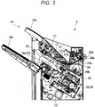
FIG. 3 is a side sectional view illustrating a main part configuration of the post-processing apparatus; -
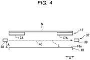
FIG. 4 is a schematic diagram illustrating a standby tray and a processing tray of the post-processing apparatus; -
FIG. 5 is a schematic diagram illustrating the operation of the standby tray; -
FIG. 6 is a side sectional view schematically illustrating a main part configuration of the post-processing apparatus; -
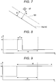
FIG. 7 is a schematic diagram illustrating a relation between a sensor and the processing tray of the post-processing apparatus; -
FIG. 8 is a diagram illustrating detection values of the sensor; and -
FIG. 9 is a diagram illustrating detection values of the sensor. - An object of embodiments is to provide a post-processing apparatus that can sufficiently secure the number of post-process able sheets and is excellent in safety.
- Apost-processingapparatus according to an embodiment includes a processing tray, a post-processing section, a sensor, and a control section. A sheet supplied from an image forming apparatus is led into the processing tray through a lead-in path. The post-processing section applies post-processing to the sheet sent from the processing tray. The sensor detects an object passing a detection space in the lead-in path. The control section controls operation of the post-processing section based on a time in which the sensor detects the object.
- Apost-processing apparatus according to an embodiment is explained below with reference to the drawings.
- A
post-processing apparatus 3 in animage forming system 1 according to an embodiment is explained with reference toFIGS. 1 to 7 . - As illustrated in
FIG. 1 , theimage forming system 1 includes animage forming apparatus 2 and thepost-processing apparatus 3. For example, theimage forming apparatus 2 is a multi function peripheral (hereinafter referred to as "MFP"). Theimage forming apparatus 2 forms an image on a sheet-like recording medium (hereinafter referred to as "sheet S") such as paper. Thepost-processing apparatus 3 performs post-processing on the sheet S conveyed from theimage forming apparatus 2. A stacked plurality of sheets S are referred to as sheet bundle SS (seeFIG. 7 ). - The
image forming apparatus 2 includes a control panel (an operation section) 5, ascanner section 6, aprinter section 7, apaper feeding section 8, and apaper discharging section 9. Thecontrol panel 5 includes various keys, a touch panel, or the like that receives operation of a user. Thecontrol panel 5 receives an input concerning a type of post-processing for the sheet S. For example, with thecontrol panel 5, it is possible to select a sort mode in which sorting is performed, a staple mode in which stapling is performed, or a non-sort mode in which the sorting and the stapling are not performed. - If the non-sort mode is selected, the
control panel 5 receives selection concerning whether the sheet S is discharged to a fixedtray 14a of thepost-processing apparatus 3 or the sheet S is discharged to amovable tray 14b of thepost-processing apparatus 3. Theimage forming apparatus 2 sends, to thepost-processing apparatus 3, information concerning a type of post-processing input from thecontrol panel 5. - The
scanner section 6 includes a reading section that reads image information of a copying target object. Thescanner section 6 sends the read image information to theprinter section 7. Theprinter section 7 forms an output image with a developer such as toner based on the image information transmitted from thescanner section 6 or an external apparatus. Theprinter section 7 applies heat and pressure to a toner image transferred onto the sheet S and fixes the toner image on the sheet S. - The
paper feeding section 8 supplies the sheets S to theprinter section 7 one by one according to timing when theprinter section 7 forms a toner image. Thepaper discharging section 9 conveys the sheet S discharged from theprinter section 7 to thepost-processing apparatus 3. - The
post-processing apparatus 3 is explained. - The
post-processing apparatus 3 is disposed adjacent to theimage forming apparatus 2. Thepost-processing apparatus 3 executes, on the sheet S conveyed from theimage forming apparatus 2, post-processing designated through thecontrol panel 5. For example, the post-processing is stapling, punching, folding, and bookbinding. In this embodiment, the stapling is adopted as the post-processing. Therefore, thepost-processing apparatus 3 is a stapling apparatus. - The
post-processing apparatus 3 includes astandby section 12, aprocessing section 13, a dischargingsection 14, and apost-processing control section 15. Thestandby section 12 temporarily holds up (buffers) the sheet S conveyed from theimage forming apparatus 2. Thestandby section 12 includes astandby tray 17. For example, thestandby section 12 puts a following plurality of sheets S on standby while post-processing of preceding sheets S is performed in theprocessing section 13. Thestandby section 12 is provided above theprocessing section 13. For example, thestandby section 12 superimposes a preset plurality of sheets S and puts the plurality of sheets S on standby. If theprocessing section 13 is emptied, thestandby section 12 drops the held-up sheets S toward theprocessing section 13. - The
processing section 13 performs post-processing on the sheets S conveyed to theprocessing section 13. Theprocessing section 13 includes aprocessing tray 18. Theprocessing section 13 performs stapling, which is binding by a stapler, on the sheet bundle SS (seeFIG. 7 ) of the number of sheets to be stapled obtained by aligning a plurality of sheets S. Theprocessing section 13 discharges the sheets S subjected to the post-processing to the dischargingsection 14. - As illustrated in
FIGS. 1 to 3 , the fixedtray 14a of the dischargingsection 14 is provided in an upper part of thepost-processing apparatus 3. Themovable tray 14b is provided in a side part of thepost-processing apparatus 3. Themovable tray 14b is movable in the up-down direction along the side part of thepost-processing apparatus 3. The sheet S is discharged to the fixedtray 14a and themovable tray 14b. - The post-processing control section 15 (see
FIG. 1 ) controls the operation of the entirepost-processing apparatus 3. That is, thepost-processing control section 15 controls thestandby section 12, theprocessing section 13, and the dischargingsection 14. Thepost-processing control section 15 controls the operation ofinlet rollers outlet rollers post-processing control section 15 is formed by a control circuit including a CPU, a ROM, and a RAM. - The configurations of the sections of the
post-processing apparatus 3 are explained in detail with reference toFIG. 3 . - In this embodiment, an "upstream side" and a "downstream side" respectively mean an upstream side (the
image forming apparatus 2 side) and a downstream side (the fixedtray 14a side or themovable tray 14b side) in a conveying direction of the sheet S. A "front end portion" and a "rear end portion" respectively mean a "downstream side end portion" and an "upstream side end portion" in the sheet conveying direction. A direction substantially parallel to the plane of the sheet S (a sheet surface direction) and substantially orthogonal to the sheet conveying direction is referred to as sheet width direction W (seeFIG. 4 ). A view from a direction parallel to the sheet width direction W is referred to as side view. - As illustrated in
FIGS. 1 and3 , thepost-processing apparatus 3 includes aconveyance path 26 for conveying the sheet S led in from thepaper discharging section 9 of theimage forming apparatus 2. A pair ofinlet rollers outlet rollers conveyance path 26. Theconveyance path 26 is provided on the inside of thepost-processing apparatus 3. - As illustrated in
FIG. 3 , theconveyance path 26 includes asheet supply port 26a and asheet discharge port 26b. Thesheet supply port 26a faces the paper discharging section 9 (seeFIG. 1 ) of theimage forming apparatus 2. The sheet S is supplied to thesheet supply port 26a from theimage forming apparatus 2. Thesheet discharge port 26b faces thestandby section 12. The sheet S passed through theconveyance path 26 is conveyed to thestandby section 12 from thesheet discharge port 26b. - The
post-processing apparatus 3 includes asecond conveyance path 26c (seeFIG. 1 ) extending toward the fixedtray 14a of the dischargingsection 14. Thesecond conveyance path 26c is formed to branch from theconveyance path 26. Thesecond conveyance path 26c guides the sheet S toward the fixedtray 14a in the non-sort mode. Theconveyance path 26 guides the sheet S to thestandby section 12 if the sort mode or the staple mode is selected. - The
inlet rollers sheet supply port 26a. Theinlet rollers inlet roller 20a is a driving roller disposed on the upper surface side of theconveyance path 26. Theinlet roller 20b is a driven roller disposed on the lower surface side of theconveyance path 26. Theinlet rollers inlet rollers - The
outlet rollers sheet discharge port 26b. Theoutlet rollers outlet roller 21a is a driven roller disposed on the upper surface side of theconveyance path 26. Theoutlet roller 21b is a driving roller disposed on the lower surface side of theconveyance path 26. Theoutlet rollers outlet rollers - The
standby section 12 is explained. - The
standby section 12 includes the standby tray (a buffer tray) 17. The rear end portion of thestandby tray 17 is located in the vicinity of theoutlet rollers standby tray 17 is located below thesheet discharge port 26b of theconveyance path 26. Thestandby tray 17 is inclined with respect to the horizontal direction to be gradually higher toward the downstream side in the sheet conveying direction. Thestandby tray 17 superimposes a plurality of sheets S and puts the plurality of sheets S on standby while the post-processing is performed in theprocessing section 13. - As illustrated in
FIG. 4 , thestandby tray 17 includes a pair oftray members tray members standby tray 17. - As illustrated in
FIG. 5 , the pair oftray members standby tray 17 toward theprocessing tray 18. Since the distance between thetray members processing tray 18. A path through which the sheet S is moved from thestandby tray 17 to theprocessing tray 18 is a lead-inpath 19 through which the sheet S is led into theprocessing tray 18. - The
processing section 13 is explained. - As illustrated in
FIG. 3 , theprocessing section 13 includes theprocessing tray 18,lateral alignment plates 33, a rear end stopper 32, aguide 34, a stapler (a binding section, a post-processing section) 35, an ejector 36, and asensor 37. The stapler is referred to as stapling section as well. - The
processing tray 18 is provided in a position lower than thestandby tray 17. Theprocessing tray 18 is inclined with respect to the horizontal direction to be gradually higher toward the downstream side in the sheet conveying direction. For example, theprocessing tray 18 is substantially parallel to thestandby tray 17. Theprocessing tray 18 includes aconveyance surface 18a that supports the sheet S (i.e., on which the sheet S is placed) . - A pair of
lateral alignment plates 33 is provided to be opposed to both sides in the sheet width direction W (seeFIG. 4 ) of theconveyance surface 18a of theprocessing tray 18. The pair oflateral alignment plates 33 is provided to be separated from each other in the sheet width direction W. Thelateral alignment plates 33 are movable in a direction in which thelateral alignment plates 33 approach each other and a direction in which thelateral alignment plates 33 separate from each other in the sheet width direction W. Thelateral alignment plates 33 configure a lateral alignment device that performs alignment (so-called lateral alignment) of the sheet S in the sheet width direction W. - The rear end stopper 32 is provided at the end portion on the upstream side of the
processing tray 18. The end on the upstream side of the sheet S placed on theprocessing tray 18 is brought into contact with the rear end stopper 32, whereby the rear end stopper 32 vertically aligns the sheet S. - As illustrated in
FIGS. 3 and6 , theguide 34 is provided to face theprocessing tray 18. As illustrated inFIG. 6 , clearance C between theconveyance surface 18a of theprocessing tray 18 and theguide 34 is desirably set smaller than the thickness (the diameter) of a finger of the user. Consequently, the finger of the user less easily enters thestapler 35 from theprocessing tray 18. Therefore, it is possible to improve safety. - If the clearance C is decided based in the thickness (the diameter) of a finger of an adult, a slender finger of a child is likely to pass through the gap between the
conveyance surface 18a and theguide 34. However, in thepost-processing apparatus 3, as explained below, thestapler 35 stops if the finger of the user passes through the gap between theconveyance surface 18a and theguide 34 and reaches a detection space 40 (seeFIGS. 4 and5 ). Therefore, it is possible to secure safety. - As illustrated in
FIG. 3 , thestapler 35 is disposed behind theprocessing tray 18. Thestapler 35 is capable of clinching the end portion of the sheet S coming into contact with the rear end stopper 32 and aligned. If the staple mode is selected, thestapler 35 performs stapling on the end portion of the sheet bundle SS (seeFIG. 7 ) coming into contact with the rear end stopper 32 and aligned. - The ejector 36 is capable of moving the sheet S toward the conveying direction downstream side. The ejector 36 advances the sheet bundle SS subjected to the stapling.
- As illustrated in
FIG. 4 , for example, thesensor 37 is a transmission-type sensor including alight emitting section 38 and alight receiving section 39. For example, thelight emitting section 38 includes a light emitting element such as a photodiode. Thelight receiving section 39 receives detection light L emitted by thelight emitting section 38. For example, thelight receiving section 39 includes a light receiving element such as a phototransistor. Thelight emitting section 38 and thelight receiving section 39 are disposed to be opposed to each other at an interval in the sheet width direction W. If the intensity of the detected detection light L is smaller than a threshold, thelight receiving section 39 detects an object present in thedetection space 40 and outputs a detection signal to thepost-processing control section 15. Thedetection space 40 is a space between thelight emitting section 38 and thelight receiving section 39. At least a part of thedetection space 40 is included in the lead-in path 19 (seeFIG. 5 ). - As illustrated in
FIGS. 3 and7 , thesensor 37 is located in a position lower than thestandby tray 17 and higher than theprocessing tray 18 when viewed from the direction parallel to the sheet width direction W. As illustrated inFIG. 7 , a distance A (seeFIGS. 4 and5 ) of thesensor 37 from theconveyance surface 18a of theprocessing tray 18 is larger than thickness B of the sheet bundle SS of a maximum number of sheets to be stapled. Therefore, after the sheets S are mounted on theprocessing tray 18, even if the number of sheets S reaches the maximum number of sheets to be stapled, the sheet bundle SS does not block the detection light L (seeFIG. 4 ) and is not detected by thesensor 37. - The
sensor 37 is a transmission-type sensor. Therefore, compared with a reflection-type sensor, it is possible to surely detect an object on which surface reflection less easily occurs. - An example of the operation of the
post-processing apparatus 3 is explained. - As illustrated in
FIG. 3 , the sheet S sent from thepaper discharging section 9 of theimage forming apparatus 2 to theconveyance path 26 is sent to thestandby tray 17 of thestandby section 12. - As illustrated in
FIGS. 4 and5 , the sheet S drops from thestandby tray 17 with the own weight to be led into theprocessing tray 18. The sheet S dropped from thestandby tray 17 passes thedetection space 40 in a process for moving to theprocessing tray 18. In this case, since the sheet S blocks the detection light L, the intensity of the detection light L reaching thelight receiving section 39 is smaller than the threshold. -
FIGS. 8 and 9 are diagrams illustrating detection values of thesensor 37. The horizontal axis indicates time (T) and the vertical axis indicates a detection value (V) of thesensor 37. - As illustrated in
FIG. 8 , if the sheet S passes thedetection space 40, the intensity of the detection light L received by thelight receiving section 39 is smaller than the threshold. Therefore, the detection value rises from a base value V1 to a detection value V2. - If the sheet S deviates from the detection space 40 (i.e., if the sheet S passes the detection space 40), the intensity of the detection light L received by the
light receiving section 39 returns to a value equal to or larger than the threshold. The detection value decreases to the base value (V1). A time t1 in which the detection value is V2 is a time in which thesensor 37 detects the sheet S. The sheet S passes thedetection space 40 in a short time by a freefall. Therefore, the time t1 in which thesensor 37 detects the sheet S is short. - As illustrated in
FIG. 9 , if an object different from the sheet S, for example, the finger of the user (in particular, the child) enters thedetection space 40, the finger blocks the detection light L. Therefore, the detection value rises from the base value V1 to the detection value V2. Unlike the sheet S, the finger does not immediately deviate from thedetection space 40. Therefore, a time t2 in which thesensor 37 detects the finger is long compared with the time t1 (seeFIG. 8 ). - The post-processing control section 15 (see
FIG. 1 ) controls the operation (work and stop) of thestapler 35 based on a time in which thesensor 37 detects the object. That is, as illustrated inFIG. 8 , if the time t1 in which thesensor 37 detects the object is smaller than a preset setting value t3, thepost-processing control section 15 causes thestapler 35 to continue the operation. As illustrated inFIG. 9 , if the time t2 in which thesensor 37 detects the object is equal to or larger than the setting value t3, thepost-processing control section 15 sends a stop signal to thestapler 35. Thestapler 35 stops. Therefore, for example, if the finger of the user (in particular, the child) enters thedetection space 40, it is possible to prevent an accident due to thestapler 35 and secure safety. - If the
stapler 35 is stopped based on a result of the detection by thesensor 37, the stop of thestapler 35 due to the object detection by thesensor 37 may be displayed on, for example, a display of the control panel 5 (seeFIG. 1 ) . - The sheets S placed on the
conveyance surface 18a of theprocessing tray 18 are held up until the sheets S are stacked to form the sheet bundle SS of the number of sheets to be stapled. If the sheets S on theprocessing tray 18 form the sheet bundle SS of the number of sheets to be stapled, thestapler 35 performs stapling on the sheet bundle SS. The ejector 36 discharges the sheet bundle SS for which the stapling is ended. - If the
stapler 35 is stopped based on the detection result by the sensor 37 (seeFIG. 9 ), the detection by thesensor 37 is stopped and the sheets S on theprocessing tray 18 are removed. Thereafter, thepost-processing apparatus 3 is restarted. - In the
post-processing apparatus 3, since safety can be improved, it is unnecessary to dispose theguide 34 excessively low. Therefore, the number of sheets S of the sheet bundle SS sent from theprocessing tray 18 to thestapler 35 can be increased. Therefore, it is possible to sufficiently secure the number of sheets S that can be stapled. - In the embodiment explained above, the sheet S drops from the
standby tray 17 to be led into theprocessing tray 18. However, a path through which the sheet is led into the processing tray is not particularly limited. For example, the sheet may be led into the processing tray through a conveyance path for conveying the sheet in the plane direction with one or a plurality of pairs of roller. In that case, the sensor can detect the sheet conveyed through the conveyance path. - In the embodiment explained above, the image formation on the sheet S and the stapling are continuously performed using the
image forming apparatus 2 and thepost-processing apparatus 3. As a modification of the embodiment, the user may staple the sheet bundle SS with manual operation without using theimage forming apparatus 2. - In the embodiment explained above, the
post-processing apparatus 3 is separate from theimage forming apparatus 2. However, the post-processing apparatus may be integrated with the image forming apparatus. - The sensor is not limited to the transmission-type sensor. Sensors of other types may be used. For example, a reflection-type sensor including a light emitting section and a light receiving section that receives reflected light can be used. The sensor may detect an arm of the user.
- According to at least one embodiment explained above, the post-processing apparatus includes the sensor that detects an object passing the detection space and the post-processing control section (the control section) that controls the operation of the stapler (the post-processing section) based on a time in which the sensor detects the object. Therefore, for example, if the finger of the user (in particular, the child) enters the detection space, the stapler can be stopped. Therefore, it is possible to secure safety.
- According to at least one embodiment, since safety can be improved, it is unnecessary to dispose the guide excessively low. Therefore, it is possible to increase the number of sheets of the sheet bundle sent from the processing tray to the stapler. Therefore, it is possible to sufficiently secure the number of post-processable sheets.
- The several embodiments are explained above. However, the embodiments are presented as examples and are not intended to limit the scope of the invention. These new embodiments can be implemented in other various forms. Various omissions, substitutions, and changes can be made without departing from the scope of the invention. These embodiments and modifications of the embodiments are included in the scope and the gist of the invention and included in the inventions described in claims and the scope of equivalents of the inventions as defined by the appended claims.
Claims (15)
- A post-processing apparatus, comprising:a processing tray into which a sheet supplied from an image forming apparatus is led through a lead-in path;a post-processing section configured to receive the sheet sent from the processing tray and apply post-processing to the sheet;a sensor configured to detect an object passing a detection space within the lead-in path; anda control section configured to control operation of the post-processing section based on a time in which the sensor detects the object.
- The apparatus according to claim 1, wherein the control section continues the operation of the post-processing section if the time in which the sensor detects the object is smaller than a setting value and stops the operation of the post-processing section if the time in which the sensor detects the object is equal to or larger than the setting value.
- The apparatus according to claim 1 or 2, wherein the lead-in path is a path through which the sheet is led into the processing tray by dropping from the image forming apparatus and gravity.
- The apparatus according to any of claims 1 to 3, wherein the post-processing section comprises a stapling section that staples the sheet.
- The apparatus according to any of claims 1 to 4, wherein the sensor comprises a transmission-type sensor including a light emitting section and a light receiving section that receives light emitted from the light emitting section.
- The apparatus according to any of claims 1 to 5, wherein a distance of the sensor from a conveyance surface of the processing tray is larger than a thickness of a sheet bundle of a maximum number of sheets that can be stapled.
- The apparatus according to any of claims 1 to 6, wherein the processing tray receives the sheet from a standby tray of the image forming apparatus, and the sensor is positioned between the processing tray and the standby tray.
- The apparatus according to any of claims 1 to 7, wherein the processing tray receives sheets supplied from the image forming apparatus through a lead-in path and the post-processing section is configured to receive the sheets sent from the processing tray and apply post-processing to the sheets.
- The apparatus according to claim 8, wherein the sheets form a sheet bundle on the processing tray.
- The apparatus according to any of claims 1 to 9, wherein the post-processing section comprises at least one of a punching section, a folding section, and a bookbinding section.
- A post-processing method, comprising:supplying a sheet from an image forming apparatus through a lead-in path to a processing tray;sending the sheet from the processing tray to a post-processing section and apply post-processing to the sheet;detecting an object passing a detection space within the lead-in path; andcontrolling operation of the post-processing section based on a time in which the sensor detects the object.
- The method according to claim 11, further comprising:
continuing the operation of the post-processing section if the time in which detection of the object is smaller than a setting value and stopping the operation of the post-processing section if the time in which the detection of the object is equal to or larger than the setting value. - The method according to claim 11 or 12, further comprising: dropping the sheet from the image forming apparatus to the processing tray using gravity.
- The method according to any of claims 11 to 13, wherein the post-processing section comprises a stapling section that staples the sheet.
- The method according to any of claims 11 to 14, wherein the detection involves using a sensor comprising a transmission-type sensor including a light emitting section and a light receiving section that receives light emitted from the light emitting section.
Applications Claiming Priority (1)
| Application Number | Priority Date | Filing Date | Title |
|---|---|---|---|
| JP2018229376A JP2020090372A (en) | 2018-12-06 | 2018-12-06 | Aftertreatment device |
Publications (1)
| Publication Number | Publication Date |
|---|---|
| EP3663858A1 true EP3663858A1 (en) | 2020-06-10 |
Family
ID=67658797
Family Applications (1)
| Application Number | Title | Priority Date | Filing Date |
|---|---|---|---|
| EP19191700.4A Withdrawn EP3663858A1 (en) | 2018-12-06 | 2019-08-14 | Post-processing apparatus |
Country Status (4)
| Country | Link |
|---|---|
| US (2) | US11178300B2 (en) |
| EP (1) | EP3663858A1 (en) |
| JP (1) | JP2020090372A (en) |
| CN (1) | CN111285145A (en) |
Cited By (1)
| Publication number | Priority date | Publication date | Assignee | Title |
|---|---|---|---|---|
| EP3709089A1 (en) * | 2019-03-15 | 2020-09-16 | Toshiba Tec Kabushiki Kaisha | Image forming system and image forming method |
Families Citing this family (1)
| Publication number | Priority date | Publication date | Assignee | Title |
|---|---|---|---|---|
| US11272068B2 (en) * | 2020-03-10 | 2022-03-08 | Toshiba Tec Kabushiki Kaisha | Post-processing apparatus and control method |
Citations (5)
| Publication number | Priority date | Publication date | Assignee | Title |
|---|---|---|---|---|
| JP2004043037A (en) * | 2002-07-08 | 2004-02-12 | Canon Finetech Inc | Sheet handling device and image formation device furnished with the same |
| US20100007074A1 (en) * | 2008-07-08 | 2010-01-14 | Kabushiki Kaisha Toshiba | Sheet finishing apparatus and control method |
| JP2014169160A (en) * | 2013-03-04 | 2014-09-18 | Ricoh Co Ltd | Paper post-processing device |
| JP2014201434A (en) * | 2013-04-10 | 2014-10-27 | 株式会社リコー | Paper sheet post-processing device, and image forming system |
| US20170212462A1 (en) * | 2016-01-26 | 2017-07-27 | Kabushiki Kaisha Toshiba | Post-processing apparatus and image forming system |
Family Cites Families (12)
| Publication number | Priority date | Publication date | Assignee | Title |
|---|---|---|---|---|
| JP2801501B2 (en) * | 1993-08-06 | 1998-09-21 | シャープ株式会社 | Paper post-processing equipment |
| JPH08157132A (en) | 1994-12-02 | 1996-06-18 | Konica Corp | Locking device and sheet post-processing device having locking device |
| JP4143208B2 (en) * | 1999-03-15 | 2008-09-03 | キヤノン株式会社 | Sheet feeding apparatus and image forming apparatus provided with the apparatus |
| JP3874058B2 (en) * | 2000-05-24 | 2007-01-31 | 富士ゼロックス株式会社 | Sheet transport device |
| JP2004219941A (en) * | 2003-01-17 | 2004-08-05 | Kyocera Mita Corp | Image forming apparatus |
| JP4719611B2 (en) * | 2006-04-03 | 2011-07-06 | キヤノン株式会社 | Sheet feeding apparatus and image forming apparatus |
| JP5094579B2 (en) * | 2008-06-18 | 2012-12-12 | シャープ株式会社 | Image forming apparatus |
| US8226079B2 (en) * | 2009-08-04 | 2012-07-24 | Kabushiki Kaisha Toshiba | Manual stapling mode for sheet finishing apparatus |
| JP5743494B2 (en) * | 2010-11-04 | 2015-07-01 | キヤノン株式会社 | Recording material supply apparatus and image forming apparatus |
| JP5884668B2 (en) * | 2012-07-23 | 2016-03-15 | コニカミノルタ株式会社 | Post-processing apparatus and image forming apparatus |
| JP6704619B2 (en) * | 2015-12-24 | 2020-06-03 | キヤノンファインテックニスカ株式会社 | Sheet ejection device, image forming system and sheet post-processing device |
| JP6410324B2 (en) * | 2016-02-15 | 2018-10-24 | キヤノンファインテックニスカ株式会社 | Sheet stacking device |
-
2018
- 2018-12-06 JP JP2018229376A patent/JP2020090372A/en active Pending
-
2019
- 2019-07-10 US US16/507,070 patent/US11178300B2/en active Active
- 2019-08-14 EP EP19191700.4A patent/EP3663858A1/en not_active Withdrawn
- 2019-09-17 CN CN201910877606.6A patent/CN111285145A/en active Pending
-
2021
- 2021-10-14 US US17/500,993 patent/US20220070321A1/en not_active Abandoned
Patent Citations (5)
| Publication number | Priority date | Publication date | Assignee | Title |
|---|---|---|---|---|
| JP2004043037A (en) * | 2002-07-08 | 2004-02-12 | Canon Finetech Inc | Sheet handling device and image formation device furnished with the same |
| US20100007074A1 (en) * | 2008-07-08 | 2010-01-14 | Kabushiki Kaisha Toshiba | Sheet finishing apparatus and control method |
| JP2014169160A (en) * | 2013-03-04 | 2014-09-18 | Ricoh Co Ltd | Paper post-processing device |
| JP2014201434A (en) * | 2013-04-10 | 2014-10-27 | 株式会社リコー | Paper sheet post-processing device, and image forming system |
| US20170212462A1 (en) * | 2016-01-26 | 2017-07-27 | Kabushiki Kaisha Toshiba | Post-processing apparatus and image forming system |
Cited By (1)
| Publication number | Priority date | Publication date | Assignee | Title |
|---|---|---|---|---|
| EP3709089A1 (en) * | 2019-03-15 | 2020-09-16 | Toshiba Tec Kabushiki Kaisha | Image forming system and image forming method |
Also Published As
| Publication number | Publication date |
|---|---|
| CN111285145A (en) | 2020-06-16 |
| US20220070321A1 (en) | 2022-03-03 |
| JP2020090372A (en) | 2020-06-11 |
| US20200186659A1 (en) | 2020-06-11 |
| US11178300B2 (en) | 2021-11-16 |
Similar Documents
| Publication | Publication Date | Title |
|---|---|---|
| EP3461768B1 (en) | Medium feeding device and image reading apparatus | |
| US8837017B2 (en) | Image reading apparatus | |
| US9932194B2 (en) | Sheet discharge apparatus and image forming apparatus having same | |
| US9216873B2 (en) | Sheet stacking apparatus and sheet processing apparatus as well as image forming apparatus | |
| CN108693725B (en) | Sheet processing apparatus | |
| US20220070321A1 (en) | Post-processing apparatus | |
| US9760051B2 (en) | Post-processing apparatus and image forming system | |
| JP2019006540A (en) | Post-processing equipment | |
| US11167950B2 (en) | Sheet folding processing apparatus and image forming system including the same | |
| CN108975036B (en) | Image forming apparatus with a toner supply device | |
| JP4698363B2 (en) | Sheet processing apparatus and image forming apparatus | |
| US11142424B2 (en) | Sheet conveying apparatus and image forming system including same | |
| JP7348788B2 (en) | Post-processing equipment and image forming system | |
| US11285751B2 (en) | Image forming system and image forming method | |
| US20180237251A1 (en) | Sheet processing apparatus and sheet processing method | |
| JP7362452B2 (en) | Sheet transport device, image reading device, and image forming device | |
| CN206692081U (en) | After-treatment device and image formation system | |
| JP2014201434A (en) | Paper sheet post-processing device, and image forming system | |
| CN111606120B (en) | Image forming system, sheet processing apparatus, and control method thereof | |
| JP2020158293A (en) | Sheet loading device, post-processing device and image forming system | |
| US10088793B2 (en) | Post-processing apparatus and control method for controlling the post-processing apparatus | |
| JP2012182575A (en) | Document reading apparatus, image formation apparatus, and document reading method | |
| JP2015229594A (en) | Sheet processing device, and image formation device equipped with the same | |
| JP2008247564A (en) | Paper sheet aligning mechanism, and post-processing device having the same |
Legal Events
| Date | Code | Title | Description |
|---|---|---|---|
| PUAI | Public reference made under article 153(3) epc to a published international application that has entered the european phase |
Free format text: ORIGINAL CODE: 0009012 |
|
| STAA | Information on the status of an ep patent application or granted ep patent |
Free format text: STATUS: THE APPLICATION HAS BEEN PUBLISHED |
|
| AK | Designated contracting states |
Kind code of ref document: A1 Designated state(s): AL AT BE BG CH CY CZ DE DK EE ES FI FR GB GR HR HU IE IS IT LI LT LU LV MC MK MT NL NO PL PT RO RS SE SI SK SM TR |
|
| AX | Request for extension of the european patent |
Extension state: BA ME |
|
| STAA | Information on the status of an ep patent application or granted ep patent |
Free format text: STATUS: REQUEST FOR EXAMINATION WAS MADE |
|
| 17P | Request for examination filed |
Effective date: 20201119 |
|
| RBV | Designated contracting states (corrected) |
Designated state(s): AL AT BE BG CH CY CZ DE DK EE ES FI FR GB GR HR HU IE IS IT LI LT LU LV MC MK MT NL NO PL PT RO RS SE SI SK SM TR |
|
| STAA | Information on the status of an ep patent application or granted ep patent |
Free format text: STATUS: EXAMINATION IS IN PROGRESS |
|
| 17Q | First examination report despatched |
Effective date: 20220511 |
|
| STAA | Information on the status of an ep patent application or granted ep patent |
Free format text: STATUS: THE APPLICATION HAS BEEN WITHDRAWN |
|
| 18W | Application withdrawn |
Effective date: 20220729 |