EP3663849A1 - Projection d'images et de champs d'onde par l'intermédiaire d'un support diffusif - Google Patents
Projection d'images et de champs d'onde par l'intermédiaire d'un support diffusif Download PDFInfo
- Publication number
- EP3663849A1 EP3663849A1 EP20154561.3A EP20154561A EP3663849A1 EP 3663849 A1 EP3663849 A1 EP 3663849A1 EP 20154561 A EP20154561 A EP 20154561A EP 3663849 A1 EP3663849 A1 EP 3663849A1
- Authority
- EP
- European Patent Office
- Prior art keywords
- light
- wave
- light field
- diffuser
- image
- Prior art date
- Legal status (The legal status is an assumption and is not a legal conclusion. Google has not performed a legal analysis and makes no representation as to the accuracy of the status listed.)
- Pending
Links
- 238000000034 method Methods 0.000 description 78
- 238000005516 engineering process Methods 0.000 description 36
- 230000003287 optical effect Effects 0.000 description 33
- 230000008569 process Effects 0.000 description 22
- 238000009826 distribution Methods 0.000 description 20
- 239000002245 particle Substances 0.000 description 18
- 230000006870 function Effects 0.000 description 14
- 230000001427 coherent effect Effects 0.000 description 11
- 239000011521 glass Substances 0.000 description 11
- 230000005540 biological transmission Effects 0.000 description 10
- 230000003446 memory effect Effects 0.000 description 10
- 238000012545 processing Methods 0.000 description 9
- 238000003491 array Methods 0.000 description 8
- 230000003190 augmentative effect Effects 0.000 description 8
- 239000011324 bead Substances 0.000 description 8
- 239000004973 liquid crystal related substance Substances 0.000 description 8
- 230000008901 benefit Effects 0.000 description 7
- 230000010287 polarization Effects 0.000 description 7
- 230000001902 propagating effect Effects 0.000 description 7
- 238000005286 illumination Methods 0.000 description 6
- 239000000463 material Substances 0.000 description 6
- 239000011159 matrix material Substances 0.000 description 6
- 238000007493 shaping process Methods 0.000 description 6
- 230000002123 temporal effect Effects 0.000 description 6
- 239000005337 ground glass Substances 0.000 description 5
- 238000004519 manufacturing process Methods 0.000 description 5
- 230000003068 static effect Effects 0.000 description 5
- 238000002604 ultrasonography Methods 0.000 description 5
- 238000013459 approach Methods 0.000 description 4
- 230000008859 change Effects 0.000 description 4
- 210000001747 pupil Anatomy 0.000 description 4
- 239000002131 composite material Substances 0.000 description 3
- 238000010276 construction Methods 0.000 description 3
- 238000005457 optimization Methods 0.000 description 3
- 238000001356 surgical procedure Methods 0.000 description 3
- 230000009466 transformation Effects 0.000 description 3
- 230000000007 visual effect Effects 0.000 description 3
- GWEVSGVZZGPLCZ-UHFFFAOYSA-N Titan oxide Chemical compound O=[Ti]=O GWEVSGVZZGPLCZ-UHFFFAOYSA-N 0.000 description 2
- 238000000149 argon plasma sintering Methods 0.000 description 2
- 239000003086 colorant Substances 0.000 description 2
- 230000008878 coupling Effects 0.000 description 2
- 238000010168 coupling process Methods 0.000 description 2
- 238000005859 coupling reaction Methods 0.000 description 2
- 238000000354 decomposition reaction Methods 0.000 description 2
- 230000000694 effects Effects 0.000 description 2
- 210000000887 face Anatomy 0.000 description 2
- 239000000499 gel Substances 0.000 description 2
- 210000003128 head Anatomy 0.000 description 2
- 238000000386 microscopy Methods 0.000 description 2
- 238000000206 photolithography Methods 0.000 description 2
- 230000002441 reversible effect Effects 0.000 description 2
- 238000005070 sampling Methods 0.000 description 2
- 239000000243 solution Substances 0.000 description 2
- 230000003595 spectral effect Effects 0.000 description 2
- 238000013403 standard screening design Methods 0.000 description 2
- 238000003860 storage Methods 0.000 description 2
- 239000000725 suspension Substances 0.000 description 2
- XLYOFNOQVPJJNP-UHFFFAOYSA-N water Substances O XLYOFNOQVPJJNP-UHFFFAOYSA-N 0.000 description 2
- 208000002177 Cataract Diseases 0.000 description 1
- 108010010803 Gelatin Proteins 0.000 description 1
- 239000006096 absorbing agent Substances 0.000 description 1
- 230000003044 adaptive effect Effects 0.000 description 1
- 230000004075 alteration Effects 0.000 description 1
- 238000005284 basis set Methods 0.000 description 1
- 230000015572 biosynthetic process Effects 0.000 description 1
- 238000004364 calculation method Methods 0.000 description 1
- 238000005266 casting Methods 0.000 description 1
- 238000004891 communication Methods 0.000 description 1
- 238000012937 correction Methods 0.000 description 1
- 230000001351 cycling effect Effects 0.000 description 1
- 238000013016 damping Methods 0.000 description 1
- 230000007547 defect Effects 0.000 description 1
- 238000010586 diagram Methods 0.000 description 1
- 238000009792 diffusion process Methods 0.000 description 1
- 208000037265 diseases, disorders, signs and symptoms Diseases 0.000 description 1
- 239000000835 fiber Substances 0.000 description 1
- 239000008273 gelatin Substances 0.000 description 1
- 229920000159 gelatin Polymers 0.000 description 1
- 235000019322 gelatine Nutrition 0.000 description 1
- 235000011852 gelatine desserts Nutrition 0.000 description 1
- 239000005276 holographic polymer dispersed liquid crystals (HPDLCs) Substances 0.000 description 1
- 238000003384 imaging method Methods 0.000 description 1
- 230000008676 import Effects 0.000 description 1
- 230000006872 improvement Effects 0.000 description 1
- 238000001746 injection moulding Methods 0.000 description 1
- 230000003993 interaction Effects 0.000 description 1
- 238000005259 measurement Methods 0.000 description 1
- 239000011325 microbead Substances 0.000 description 1
- 238000012986 modification Methods 0.000 description 1
- 230000004048 modification Effects 0.000 description 1
- 238000000465 moulding Methods 0.000 description 1
- 239000011022 opal Substances 0.000 description 1
- 239000013307 optical fiber Substances 0.000 description 1
- 239000012188 paraffin wax Substances 0.000 description 1
- 230000010363 phase shift Effects 0.000 description 1
- 229920000642 polymer Polymers 0.000 description 1
- 230000000644 propagated effect Effects 0.000 description 1
- 238000009877 rendering Methods 0.000 description 1
- 210000001525 retina Anatomy 0.000 description 1
- 238000012552 review Methods 0.000 description 1
- 238000001228 spectrum Methods 0.000 description 1
- 238000010897 surface acoustic wave method Methods 0.000 description 1
- 238000012876 topography Methods 0.000 description 1
- 238000012546 transfer Methods 0.000 description 1
- 239000013598 vector Substances 0.000 description 1
Images


Classifications
-
- H—ELECTRICITY
- H04—ELECTRIC COMMUNICATION TECHNIQUE
- H04N—PICTORIAL COMMUNICATION, e.g. TELEVISION
- H04N9/00—Details of colour television systems
- H04N9/12—Picture reproducers
- H04N9/31—Projection devices for colour picture display, e.g. using electronic spatial light modulators [ESLM]
- H04N9/3179—Video signal processing therefor
- H04N9/3185—Geometric adjustment, e.g. keystone or convergence
-
- G—PHYSICS
- G02—OPTICS
- G02B—OPTICAL ELEMENTS, SYSTEMS OR APPARATUS
- G02B27/00—Optical systems or apparatus not provided for by any of the groups G02B1/00 - G02B26/00, G02B30/00
- G02B27/01—Head-up displays
- G02B27/0101—Head-up displays characterised by optical features
- G02B27/0103—Head-up displays characterised by optical features comprising holographic elements
-
- G—PHYSICS
- G02—OPTICS
- G02B—OPTICAL ELEMENTS, SYSTEMS OR APPARATUS
- G02B27/00—Optical systems or apparatus not provided for by any of the groups G02B1/00 - G02B26/00, G02B30/00
- G02B27/01—Head-up displays
- G02B27/017—Head mounted
- G02B27/0172—Head mounted characterised by optical features
-
- G—PHYSICS
- G03—PHOTOGRAPHY; CINEMATOGRAPHY; ANALOGOUS TECHNIQUES USING WAVES OTHER THAN OPTICAL WAVES; ELECTROGRAPHY; HOLOGRAPHY
- G03H—HOLOGRAPHIC PROCESSES OR APPARATUS
- G03H1/00—Holographic processes or apparatus using light, infrared or ultraviolet waves for obtaining holograms or for obtaining an image from them; Details peculiar thereto
- G03H1/26—Processes or apparatus specially adapted to produce multiple sub- holograms or to obtain images from them, e.g. multicolour technique
- G03H1/28—Processes or apparatus specially adapted to produce multiple sub- holograms or to obtain images from them, e.g. multicolour technique superimposed holograms only
-
- G—PHYSICS
- G02—OPTICS
- G02B—OPTICAL ELEMENTS, SYSTEMS OR APPARATUS
- G02B27/00—Optical systems or apparatus not provided for by any of the groups G02B1/00 - G02B26/00, G02B30/00
- G02B27/01—Head-up displays
- G02B27/0101—Head-up displays characterised by optical features
- G02B2027/013—Head-up displays characterised by optical features comprising a combiner of particular shape, e.g. curvature
-
- G—PHYSICS
- G02—OPTICS
- G02B—OPTICAL ELEMENTS, SYSTEMS OR APPARATUS
- G02B27/00—Optical systems or apparatus not provided for by any of the groups G02B1/00 - G02B26/00, G02B30/00
- G02B27/01—Head-up displays
- G02B27/017—Head mounted
- G02B27/0172—Head mounted characterised by optical features
- G02B2027/0174—Head mounted characterised by optical features holographic
-
- G—PHYSICS
- G02—OPTICS
- G02B—OPTICAL ELEMENTS, SYSTEMS OR APPARATUS
- G02B27/00—Optical systems or apparatus not provided for by any of the groups G02B1/00 - G02B26/00, G02B30/00
- G02B27/01—Head-up displays
- G02B27/017—Head mounted
- G02B2027/0178—Eyeglass type
-
- G—PHYSICS
- G03—PHOTOGRAPHY; CINEMATOGRAPHY; ANALOGOUS TECHNIQUES USING WAVES OTHER THAN OPTICAL WAVES; ELECTROGRAPHY; HOLOGRAPHY
- G03H—HOLOGRAPHIC PROCESSES OR APPARATUS
- G03H1/00—Holographic processes or apparatus using light, infrared or ultraviolet waves for obtaining holograms or for obtaining an image from them; Details peculiar thereto
- G03H1/04—Processes or apparatus for producing holograms
- G03H1/0402—Recording geometries or arrangements
- G03H2001/0434—In situ recording when the hologram is recorded within the device used for reconstruction
-
- G—PHYSICS
- G03—PHOTOGRAPHY; CINEMATOGRAPHY; ANALOGOUS TECHNIQUES USING WAVES OTHER THAN OPTICAL WAVES; ELECTROGRAPHY; HOLOGRAPHY
- G03H—HOLOGRAPHIC PROCESSES OR APPARATUS
- G03H1/00—Holographic processes or apparatus using light, infrared or ultraviolet waves for obtaining holograms or for obtaining an image from them; Details peculiar thereto
- G03H1/04—Processes or apparatus for producing holograms
- G03H1/0402—Recording geometries or arrangements
- G03H2001/0439—Recording geometries or arrangements for recording Holographic Optical Element [HOE]
Definitions
- the present technology is directed to projection of wave fields through diffusive media, and more particularly to methods and systems for projecting images through non-conventional scattering elements.
- the linear nature of light propagation allows a direct method for recovering an image from light emitted by an object and then diffused in transmission through a diffusing medium.
- the diffused or scattered pattern resulting from light emitted by a single object point can be interpreted as an encoded version of the light from that object point.
- the diffused or scattered pattern resulting from light emitted by multiple object points is, in the case of incoherent illumination, simply the linear superposition of the encoded versions of all the individual object points.
- Embodiments of the current technology which is based on a realization that the decoding process can be inverted, form an encoded light field that, upon transmission through a diffusing medium, is decoded to form a desired light field which forms a complex image.
- the complex image can focus on a two-dimensional or three-dimensional surface of arbitrary shape.
- the complex image can comprise a real three-dimensional image in free space.
- a "conventional scattering element” is an element whose function is to add an effectively linear or effectively quadratic phase function (or a close approximation thereto) to the phase of an incident wave field.
- Adding a linear phase function changes the direction of rays in the wave field uniformly across the optical element, so for example a mirror comprises a single linear phase function CSE, while a prism comprises a pair of linear phase function CSEs (one at the entrance surface and one at the exit surface).
- Adding a quadratic phase function changes the direction of rays in the wave field in a way that varies across the optical element.
- a parabolic mirror is a radially symmetric quadratic CsE
- an ordinary lens is a pair of radially symmetric quadratic CsEs (i.e., the front and back surfaces of the lens).
- simple diffraction gratings qualify as linear CsEs
- Fresnel zone plates qualify as quadratic CsEs.
- NCSE non-conventional scattering element
- static NCSEs include: complex holograms, random ground-glass diffusers, shower glass, diffuse reflectors, lenslet arrays, retroreflective bead arrays, and transmissive elements made from scattering media.
- programmable NCSEs include: micromirror arrays, liquid crystal spatial light modulators, and deformable mirrors.
- An example non-conventional scattering element that may be incorporated in some embodiments of the present technology is a complex holographic element.
- a complex holographic element is any optical element that, via diffraction, applies a substantially more complicated transformation to a light field than is applied by a CSE.
- a diffuser may be used as an NCSE, to transform a first class of incident wave fields to a second class of wave fields. For example, a wave field appropriately matched to a specific diffuser is transformed by that diffuser to a wave field that focuses to a point.
- Figure 1 illustrates a predistorted wave field 101 entering a diffuser 103, then being re-shaped by the diffuser 103 into a second wave field 105 which converges to a point 107.
- This illustrates the projection to a single point in a projection volume.
- This approach can be extrapolated to generate more complex images.
- a linear superposition of other wave fields configured to illuminate other points in the projection volume can be provided simultaneously to generate a complex image comprising many points (voxels) in the projection volume.
- the contrast of a focused point formed in a light field through a diffuser is proportional to N/M, where N is the number of degrees of freedom in the light field, and M is the number of points being focused to.
- N is the number of degrees of freedom in the light field
- M is the number of points being focused to.
- sub-frame projection is to rapidly project many sub-frame light fields sequentially, each of which comprises a portion of the image to be projected.
- the sub-frame light fields can comprise columns or lines of pixels in the image.
- the sub-frame light fields may comprise image segments, with the image segmented into regions in which contrast or resolution has different levels of visual importance, such as human faces versus background, or important alphanumeric updates versus ongoing image content.
- the image may be segmented according to regions of viewer attention.
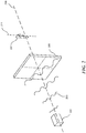
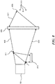
- Figure 2 illustrates a wave field projector 201 emitting a predistorted wave field 203 which enters a diffuser 205 then forms an image 207 after re-shaping by the diffuser 205.
- the wave field 203 propagates approximately along the direction of optical axis 209.
- Light passing through the diffuser 205 illuminates a plurality of voxels in the projection volume to generate one column 211 of voxels in the image 207, here having the shape of the letter "F".
- I refer to this method of projection, in which only a relatively small fraction of the total number of voxels in an image are projected at any instant, as "sub-frame projection".
- the entire image 207 is generated by sequentially generating each of the columns of voxels comprising image 207.
- One way to optimize the visual quality of an image projected according to the present technology is a combination of a) providing a large number of degrees of freedom in the light field projector (such as using multiple spatial light modulators or OLED arrays), b) designing and constructing the diffuser to direct light preferentially to the pixel array that will be displayed, c) further designing and constructing the diffuser to direct light only to an eyebox in which a viewer's eyes will be, and d) matching the light field projector controller's degrees of freedom with the diffuser so that a set of control states corresponds to a set of light field configurations which in turn correspond to predetermined columns or rows of pixels in the displayed image.
- a light field projector that can switch configurations much faster than the standard video projection frame rate can be used. Most liquid crystal devices are not fast enough to do this. However, MEMS devices such as micromirror projectors can switch on a microsecond timescale. The preferred light field projector has very short switching time so that it can rapidly project sub-frame image components.
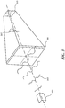
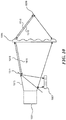
- Figure 3 illustrates an image visible through an eyebox 313 in a light field formed by transmission of a wavefront 203 through a diffuser 205.
- the components are similar to that of Figure 2 except that the eyebox 313 is added to represent the intended viewing area from which a viewer would see the image 207.
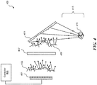
- Figure 4 illustrates a system 400 including a wave field generator 401 coupled to a controller 403.
- a first wave field 405 is emitted from the wave field generator 401 towards a first diffuser 407, which is a transmissive diffuser.
- a second wave field 409 is emitted from the first diffuser 407 towards a second diffuser 411, which is a reflective diffuser.
- Light reflected from the second diffuser 411 is focused into the projection volume 413 to generate an image visible to an observer 415.
- the wave field generator 401 can have any of several different forms such as an array of conventional projectors, or multiple wavefront-shaping transducers illuminated by coherent or incoherent waves.
- the terms, "wave field generator” and “wave front shaper” are interchangeable, because a wave front shaper can form an arbitrary wave field by being illuminated by an initial wave field such as a collimated monochromatic laser beam and reshaping the initial wave field as needed.
- the first and second diffusers 407 and 411 can have any of several different forms, such as ground-glass diffusers, "shower glass” diffusers, bumpy reflective surfaces, corrugated glass, or media with nonuniform refractive index or propagation speed.
- the diffusing properties of the diffusers can be random.
- the diffusers may be transmissive, reflective, or both. Scattering within each diffuser may be single or multiple.
- the diffusers can have any shape such as flat or curved.
- the wave field generator 401 can be calibrated to accommodate the characteristics of the first and second diffusers 407 and 411.
- some methods of associating light fields at the input end of a complex optical system with light fields at the output end of the optical system - that is, methods for calibrating the optical system - are known, that association has only been used in prior approaches for seeing through the optical system, as in microscopy, photography through turbid media, astronomy, and long-distance photography.
- embodiments of the current technology can accomplish the opposite result: to project an image through a diffusive or scattering optical system. This can be accomplished by calculating an input light field required to form a desired output light field after passing through a given complex, scattering, or diffusive optical system.
- a desired object light field may be represented as a linear sum of plane waves, and the light field that must be projected into the diffusing medium to form the desired object light field will be a linear sum of the corresponding component light fields.
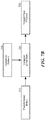
- Figure 5 illustrates an example process 500 for projecting an image through a diffusive medium and into a projection volume.
- the process begins in block 501 with calibrating the light projector to determine light fields corresponding to a number of points in the projection volume. As noted above, this calibration may be accomplished using a number of different approaches.
- the process continues in block 503 with providing an image to be displayed in the projection volume as a sum of points to be illuminated in the projection volume.
- the process continues in block 505 with determining the light field corresponding to each of the points to be illuminated in the projection volume. For example, if a static image to displayed in the projection volume consists of 1000 points to be illuminated, then the corresponding light field can be calculated for each of those 1000 points.
- the linear superposition of the determined light fields is calculated.
- the process would involve calculating the linear superposition of the 1000 light fields that correspond to illumination of the 1000 identified points in the projection volume.
- a light field is projected that corresponds to the calculated linear superposition.
- each of the indicated points in the projection volume will be illuminated, producing the desired image in the projection volume.
- the image may be three-dimensional or two-dimensional, and may be static or dynamic (e.g., video).
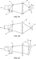
- Figures 6A and 6B illustrate a projection system in which a holographic diffuser is constructed to provide the desired optical characteristics for projection of images.
- Figure 6A illustrates a projection system according to the present technology, comprising an array of point light sources 601, a first volume holographic diffuser 603, a second diffuser 605, and an array of points in a projection volume 607.
- light 604 from the point light source 601 is reflected and redirected by the holographic diffuser 603 as light 610 towards the second diffuser 605, which focuses the light 608 onto a particular point 607.
- Figure 6B illustrates a method for creating one component of the holographic diffuser 603 in Figure 6A .
- light 609 from a coherent laser source is directed towards a particular point 611 which corresponds to the position that a light source 601 will be positioned in the system of Figure 6A .
- light 613 is emitted from a point 615 which corresponds to the position of point 607 in the projection volume of Figure 6A and is coherent with respect to light 609.
- Light emitted from point 615 is scattered via the transmissive diffuser 605 as light 614 and propagates towards the holographic diffuser 603.
- the interference between the light 613 from the point 615 and the reference beam 609 enables the construction of a particular component of the holographic diffuser 603; which component will, as in Figure 6A , result in light from point source 601 being focused to projection space point 607.
- a separate exposure may be made for each pair of point positions 611 and 615. Note that no calibration is necessary for the system of Figure 6A . Because, the holographic element 603 automatically shapes wavefront 610 to form the requisite image components 607.
- a calibration step will typically be performed first.
- Various calibration techniques are possible and several will be described in detail below.
- One such calibration technique for a light wave field projector is to place multiple retroreflective particles in the region where an image is to be formed, as illustrated in Figure 8 .
- a random light field is projected through the diffusing media. Some of the light falls upon the retroreflective particles and returns to the light field projector.
- the light field is varied under control of an optimization algorithm, until a light field is found that directs a maximum amount of light onto a single retroreflective particle.
- the methods that use a wavefront shaper can often find an optimum by simply varying one element of the wavefront shaper at a time, seeking maximum brightness of a return signal (e.g., from the retroreflective particle). An algorithm cycles through all the elements of the wavefront shaper multiple times, seeking an maximum return for each element, until no further improvement is found.
- the methods that are purely mathematical typically start with a guess at the phase components of the scatter pattern, and represent the light field at the camera as "sqrt(brightness of scatter pattern) x exp(i x theta)" where theta is the phase (a function of x and y at the camera sensor array).
- the amplitude (sqrt(brightness of scatter pattern)) known from the camera image of the scatter pattern, is a first constraint.
- a mathematical transformation is done to move the representation to the Fourier domain, where other constraints are applied, such as requiring the autocorrelation of the scatter pattern to be a delta function.
- the further-constrained estimate of the scatter pattern light field is transformed back to the spatial domain where the amplitude constraint is applied again, and so on, cycling between spatial and Fourier domains and re-applying the constraints each time, until the quality of the solution is good enough.
- the quality of the solution corresponds to how well both sets of constraints are satisfied.
- That optimum light field is an encoded version of an image point corresponding to the location of that single retroreflective particle. The process is repeated until an encoded version is found for each of the retroreflective particles. Note that this calibration process is very similar to the calibration process outlined in Ref. 1 Physical Review Letters 193905, May 2011, "Scattering lens resolves sub-100 nm structures with visible light ". It is also analogous to the method used in Ref. 2 Optics Letters Vol. 32, No. 16, Aug. 15, 2007, “Focusing coherent light through opaque strongly scattering media ". Each of these documents is hereby incorporated by reference in its entirety.
- the light field projector projects a linear superposition of the light fields corresponding to each of the points in the image.
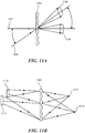
- the so-called "memory effect" ensures that if the projected light field corresponding to a point is slightly tilted, the resulting focused point is still focused but is displaced in approximate proportion to the sine of the tilt angle.
- the memory effect is illustrated in Figure 11A and 11B .
- light pattern 1109 is formed by ray 1107 incident on diffuser (or hologram) medium 1103. Tilting the angle of incidence of the ray 1107 (to form ray 1101) but keeping the position of incidence unchanged moves the light pattern 1109 to a new position 1105.
- Figure 11B illustrates an image 1115 formed by diffuser 1103 acting on light from source 1113 (which may be a point source or a more complicated wave field). Per the memory effect, moving source 1113 slightly to new position 1117 results in moving the image 1115 to new position 1111.
- source 1113 which may be a point source or a more complicated wave field.
- the focal point can be moved along the z-axis (that is, in the direction toward or away from the diffusing medium)
- the light field which converges to a given point in the projection region necessarily comprises a spherical wave.
- the spherical wave can be re-shaped to form a spherical wave centered on the new point. So, it is straightforward to calculate light fields that encode arbitrary points in a 3D region around a retroreflective particle. Therefore, it is not necessary to do calibration using retroreflective particles at every possible point in the image projection volume. If retroreflective particles are used in calibration, it is only necessary to use retroreflective particles positioned densely enough to ensure that the memory effect allows calculation of light fields corresponding to all points between the particles within the projection volume.
- retroreflective particles provide one method for calibration described herein, it is also possible to calibrate in other ways, such as using a point light source at an array of positions in the projection volume. In this case, it can actually be simpler to discover input light fields corresponding to points in the projection volume because the light field formed at the light field generator by light transmitted in the reverse direction from a point in the projection volume through the diffusing media is the conjugate of the light field that will focus at that point after passing through the diffusing media in the forward direction.
- transmission matrix measurement (well described in Chaigne et al., "Controlling light in scattering media non-invasively using the photoacoustic transmission matrix", Nature Photonics 8, 58-64 (2014 ), which is hereby incorporated by reference in its entirety) and is fundamentally equivalent to the simpler case described above.
- transmission matrix of a complex, diffusive optical system it is possible to extract the source object whose light has passed through the optical system and has been recorded at the other end of the optical system.
- a plane wave can be projected into the diffusing media from the projection volume, and the resulting light field (or portions thereof) recorded on the projector side of the diffusing medium.
- the plane wave is projected into the diffusing media at many different angles, and the light field (or portion thereof) is recorded at each angle. Because an arbitrary object can be analyzed as a linear superposition of component plane waves, and because the transmission matrix comprises a linear transformation, the recorded light field from the object, after passing through the optical system, comprises a linear superposition of component light fields, each corresponding to a different plane wave component of the object.
- Yet another alternative calibration method involves illuminating calibration patterns on a surface in the projection volume, with the patterns selected to amount to a basis set, so that any arbitrary pattern can be composed as a linear sum of the calibration patterns.
- Suitable sets of patterns include gratings of various pitch and angle, Gabor wavelets, and other such pattern sets well known in the art of image and signal processing.
- the first calibration method uses a known image (e.g., a point source of reflected light) propagated backward through the diffuser to a photosensor array and there combined with a reference beam to obtain an intensity distribution from which the phase and/or amplitude can be calculated at the location from which a light field will be projected toward the diffuser.
- a known image e.g., a point source of reflected light
- Figure 7A illustrates a method for calibrating a diffuser used in a light field projector in accordance with the first calibration method.
- Laser 701 illuminates a point on scattering screen 703. Scattered light 705 from the screen passes through diffuser 707 to camera 709. Light 711 from the same laser 701 enters the camera via beamsplitter 713. The camera 709 detects interference between light 705 and light 711, from which the phase of light 705 is inferred. By scanning the laser 701 to different points on the scattering screen 703, and by moving the screen 703 to different positions along axis 715, calibration can be performed for the entire projection volume.
- a light field projector comprising a phase-only spatial light modulator, amplitude spatial light modulator, or combined phase and amplitude spatial light modulator positioned precisely in the same position as the camera 709, projecting a light field conjugate to the calculated light field, will produce the light field that, when incident on the diffuser, will emerge to form a focus at the location of the spot on the screen 703.
- the phase and/or amplitude distribution of the scattered light 705 may be calculated from the intensity distribution at the camera 709.
- the conjugate light field then, may be projected by the light field projector to form a focused image on the surface 703 downstream from the diffuser 707.
- Figure 7B illustrates some of the information flow involved in using a light field projector.
- a predetermined image 717 and the calibration patterns 719 for the particular system are taken as inputs to compose a linear summation 721 of the calibration patterns 719 for the individual points that constitute the predetermined image 717. This linear sum is then provided to the light field projector 723.
- a light field projector 801 directs a first light field 803 onto a diffuser 805.
- the light field projector 801 can be, for example, a spatial light modulator illuminated by laser light emanating from a point.
- the first light field 803 is scattered by the diffuser 805, forming a second light field 807 downstream from the diffuser.
- the second light field 807 strikes a retroreflective bead 809, which retroreflects only light that strikes the bead. That light returns through the diffuser to form a light field on photodetector array 813, from which the phase and amplitude of the light field may be inferred.
- the emitted light field 803 is the light field which will focus to the center of retroreflective bead 809.
- the light field projector 801 can be a reflective or transmissive type, and alters the phase of the reverse-path light to form the conjugate of the light which first illuminated the light field projector 801.
- a beamsplitter 811 directs the reverse-path light to a photodetector 813.
- FIGS 9A-9C A variation on this method is shown in Figures 9A-9C .
- a spherical convex mirror 917 is used to retro-reflect light that converges toward a focus 919 corresponding to the center of curvature the spherical surface; and in Figure 9B a spherical convex mirror 921 is used to retro-reflect light that converges towards a focus 923 corresponding to the center of the mirror's curvature.
- a photodetector array 913 is used to detect the returned light field which, when optimized, will be the conjugate of the light field emitted by the light field projector 801.
- Figure 9C uses a plane mirror 925 (which, from a mathematical perspective is simply a spherical mirror whose radius of curvature is infinite) and results in calibration patterns corresponding to points at infinity.
- a third calibration method is illustrated in Figure 10 .
- This method is similar to the second calibration method described above, except that instead of directing the return light to a single photosensor 813 ( Figure 8 ), it is directed to a photosensor array 1027, whose location and position are equivalent to a reflection of spatial light modulator, which is the active component of light field projector 1001.
- the light field 1013 projected by light field projector 1001 is perfectly focused via diffuser 1005 as light field 1016onto a retroreflective bead 1009, then retroreflected back as light field 1018 and through the diffuser 1005 as light field 1015, essentially all of the light will return to beamsplitter 1011 and propagate to photosensor array 1027 and will have the same phase distribution as the light field at the projector 1001.
- the photosensor array 1027 will detect the intensity distribution of the return light, and not detect the phase distribution of the return light.
- a reference beam such as 711 ( Figure 7A ) may be provided.
- an interferometric arrangement as shown in Figure 7A can be used fairly directly to infer the phase distribution, it is not necessary to use an interferometer. Instead, it is possible to take advantage of the close mathematical relationship between the known phase distribution of the light field at the projector 801 and the intensity distribution of the light field at photosensor array 1027. Because the light field at projector 801 is known, its intensity distribution may be calculated at any plane within the light field, using techniques well-known in the field of optics.
- the intensity distribution close to the projector 801 and the intensity distribution close to the photosensor 813 will be nearly identical when the light field is precisely adjusted to be brought to a focus at the retroreflective bead 809.
- the method known as the G-S algorithm may be adapted to do the optimization relatively quickly and in a highly parallelizable form as follows:
- the memory effect may be harnessed to reduce the amount of data transfer needed to construct and project imagery using the current technology.
- the memory effect refers to the principle that, when a light ray 1101 is scattered by a diffuser 1103 to form a pattern 1105, a different light ray 1107 incident upon the same point in the diffuser 1103 but at a different angle is scattered to essentially the same pattern 1109, offset according to the change of incidence angle. This principle holds as long as the change of incidence angle is relatively small. "Relatively small” means that the angle change is small compared to the wavelength of the light divided by (pi x L), where L is the thickness of the diffuser. For example, a ground glass diffuser has effectively zero thickness.
- Figure 11B illustrates the memory effect for an image formed by a light field propagating through a diffuser or hologram.
- a light field projector 1111 projects a light field towards the diffuser 1103 which scatters and creates an image 1113.
- Positioning the light field projector 1115 at a different location may generate essentially the same image 1117 but in a translated location depending on the properties of the diffuser 1103.
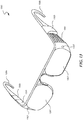
- Figures 12A and 12B illustrate an element 1200 for use in compact augmented reality eyewear.
- the eyewear may comprise a holographic directed diffuser, a 2-dimensional waveguide spatial light modulator, a laser light source, and a controller for the modulator.
- Figure 12A illustrates a method for using a holographic element in augmented-reality eyewear.
- Laser 1201 illuminates coupler 1203 along optical axis 1205.
- Light propagates via total-internal reflection (TIR) through modulator 1207, enters the holographic element 1200, and is converted by the component 1209 of the holographic element 1200 into a collimated beam 1211 which enters the pupil of the user's eye at 1213, which is shown oriented along axis 1215.
- TIR total-internal reflection
- a second component 1217 of the holographic element 1200 is also shown, which would direct light to the pupil of the user's eye from a different direction 1215.
- Figure 12B illustrates a method for making one component of the holographic element of Figure 12A , using object beam 1219 and reference beam 1221 from a coherent light source 1223.
- Any display or projector may be characterized by its number of degrees of freedom.
- a typical flat panel display with N pixels has N degrees of freedom.
- a light field projector with N projection elements, each of which projects M independently controllable light rays, has N x M degrees of freedom.
- the light field exiting the diffuser has N degrees of freedom. If the diffuser scatters each component of the illuminating light field into M different directions, the resulting exiting light field still has only N degrees of freedom. If M is greater than N, the quality with which an exit light field can be constructed is reduced, with noise in a ratio of approximately (M-N)/M. Accordingly, the quality of a light field projected using a diffuser as in this technology can be substantially improved by using a diffuser that scatters light only into a number of directions comparable to the number of degrees of freedom possessed by the light field projector that illuminates the diffuser.
- Such a diffuser is called a "directed diffuser.”
- a directed diffuser is a holographic optical element.
- a method for producing a holographic directed diffuser is illustrated in Figure 12B .
- Collimated laser light of a selected wavelength illuminates a holographic recording medium having the shape of an eyeglass lens, and light from a light field projector illuminates the same recording medium simultaneously.
- the collimated light and the projected light field are mutually temporally coherent.
- a series of N exposures are made, each with the collimated light having a different angle of incidence and with the projected light field having a different configuration.
- each of the light field configurations is orthogonal to the other configurations, in the sense that the cross-correlation of any one configuration with any other configuration is zero. Fortunately, any two light fields with random phase distributions are mutually very nearly orthogonal.
- Figures 12A and 12B illustrate, respectively, the use and the construction of a particular type of directed diffuser useful for projecting light fields with relatively few degrees of freedom, but still capable of conveying a wide-parallax three-dimensional image.
- the resulting holographic diffuser when illuminated with any one of the light field configurations, will diffract light only into the direction of the collimated light that was used together with that configuration in recording the holographic diffuser.
- the diffuser emits the linear superposition of the corresponding beams (such as beam 1211).
- the degree to which light "leaks" into undesired directions depends largely on the degree of orthogonality of the different light field configurations.
- the collimated light in each exposure step fills the eyebox or aperture associated with the holographic element 1209. It is not necessary to fill the entire recording medium. If the entire recording medium is filled, the resulting holographic diffuser will diffract light to regions outside the eye pupil. In some embodiments, the collimated light only fills the "eyebox", and thus is emitted out from only a relatively small portion of the recording medium.
- the holographic diffuser is illuminated by a superposition of the light field configurations corresponding to each of the points in the image.
- a point at infinity corresponds to a collimated beam traveling toward that point.
- N can be much bigger than n x m, on the order of 100 times larger. Larger N enables higher resolution and higher contrast in the projected image.
- Figure 13 illustrates an augmented reality eyewear system 1300, with hologram 1207 as eyeglass lens, waveguide modulator array 1301 and controller 1303 integrated in to the temple arms 1305 of the eyewear 1300.
- Two such systems operating together each serving as one lens of a pair of eyeglasses, can project one of a pair of stereographic images to each eye, thereby providing a three dimensional image.
- the images can be updated at 30 or more frames per second to provide a three dimensional video display.
- Cameras 1307 are embedded into the temple arms 1305 of the eyewear system 1300, and can be oriented to capture images (still or video) in the direction that the wearer faces.
- data from the cameras 1307 can be included to provide information to the controller 1303 regarding the environment and the location and orientation of the eyewear 1300 relative to the environment. It should be noted, if source 1223 is an array of independently addressable sources such as an OLED array, modulator 1207 may be omitted.
- the holographic element can be formed in a volume holographic recording medium such as dichromated gelatin, holographic polymer dispersed liquid crystal, or photopolymer.
- a volume hologram can, if properly recorded, be transparent to ambient light but diffract light of a specific wavelength with high angular and spectral selectivity. If the holographic diffuser is such a volume hologram, then the eyewear can be transparent to ambient light and provide a clear view of the environment, but at the same time provide a three-dimensional computer generated view or remotely recorded view superimposed on the environment.
- the eyeglass lens 1207 can be a holographic element constructed using at least three wavelengths of laser light in the ranges of red, green, and blue, in a total of at least 3xN exposures. Substantially the same wavelengths are then used in the waveguide light field projector to provide a full-color three dimensional display. Because of the high angular and spectral selectivity of the holographic diffuser, there is negligible crosstalk between the red, green, and blue image components.
- a significant advantage to using a holographic element in this and other embodiments of the technology is that it is not necessary to calibrate the diffuser (e.g., as described above) because it is constructed at the outset in such a way that there is a one-to-one correspondence between a set of light field projector controller states and the desired projected image pixels.
- Another significant advantage of using a holographic diffuser is that the diffuser is easily designed and constructed to maximize image contrast and resolution, as well as maximize light efficiency.
- the diffuser does not need to be holographic. It may be random or nonrandom. It may be transparent as in the case of a volume holographic diffuser, or opaque as in the case of a dense suspension of light scattering particles. It may be a wide angle diffuser or a narrow angle diffuser; and it may be a transmissive diffuser such as shower glass or a reflective diffuser such as a movie projection screen.
- the light field projector that illuminates the diffuser may be, for example, a waveguide light field projector, an array of lenses each backed by an emissive array such as an LED array or a VCSEL array , an array of lenses each backed by a transmissive array such as a LCD, or an array of reflective array such as an LCOS displays.
- the light source may be for example an external laser, an array of lasers, or an array of LEDs.
- visual information about the environment may be provided for example via video cameras mounted on the eyeglass frames, or by direct vision through transparent diffuser eyeglass lenses.
- the light field projector and eyeglass lens together comprise a projection system that projects a light field which is perceived by the wearer as an image in the distance.
- the image need not be at infinity nor at any specific fixed distance, and that the image can be a 3D image.
- the system projects a virtual image to the wearer's eye.
- the eyeglass lens can be a diffusive material or a volume hologram. It is advantageous to use a volume hologram because it diffuses light only of a predetermined wavelength and propagation angle (or several predetermined wavelengths and angles). Accordingly, the vast majority of ambient light is transmitted through the eyeglass lens without being altered, while light from the light field projector is redirected to the user's pupil. As a result, the wearer can see through the eyeglass lens as if it were a simple transparent lens, but virtual images projected by the eyewear are perceived as overlain on the ambient scene.
- the eyeglass lens can independently perform the function of vision correction.
- the wearer's eye is considered to be part of the optical system, and if light field components correspond to specific patterns such as gratings or points on the eye's retina, then the virtual reality or augmented reality eyewear can compensate for aberrations in the eye, and even for cataracts and other such complex optical defects.
- the embodiment as described above is not limited to use as an augmented reality display.
- it may be used for viewing videos, or as a heads-up instrument display, or as a communication device.
- it may be used in a virtual reality system or in a telepresence system such as a system for operating a drone or a robot.
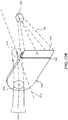
- a large directed diffuser 1401 such as a holographic diffuser may be illuminated by a light field projector 1403 to provide a wide-angle, full-parallax three-dimensional display through an eyebox 1405 through which viewers 1407 can view the image. Illumination may be accomplished via reflection as in Figure 14 , via total internal reflection and an input coupler 1509 as illustrated in Figure 15 , or by transmission as illustrated in Figure 16 . It is advantageous for the diffuser to diffuse light only into an eyebox aperture where viewer's eyes will be, as illustrated in Figure 17 , both to maximize power efficiency and to reduce the number of degrees of freedom that must be controlled.
- the diffuser for this embodiment may be desirable to manufacture in the form of a surface relief structure which can be mass-produced by well-known methods such as UV casting, injection molding or pressure molding.
- each image point may be formed by rays converging or diverging from a wide range of angles. Therefore, any image point can be viewed from a wide range of angles. This is in contrast to three-dimensional displays that project stereographic views to a narrow range of angles or positions, so that when a viewer moves side to side, the image appears to jump.
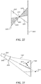
- image points may be given the appearance of being opaque or transparent. This is illustrated in Figure 22 , where light that might appear from a point behind projected object 2208 is absent as viewed from region 2205, while it is present as viewed from region 2207, thereby making object 2208 appear opaque.
- Figure 22 illustrates a ray representation of a portion of a light field forming a real image.
- Light propagates from the diffuser 2200 towards a focal point 2201 and to a viewing plane 2203.
- a first portion 2205 of the light field forms a real image viewable from the viewing plane 2203, while the second portion 2207 of the light field does not form a real image visible from the viewing plane 2203.
- any subset of the projected light field will form a corresponding subset of the desired light field in the projection volume, and that the resolution improves as the projected subset is made larger either by using a greater density of sampling or by using a wider range of sampling angles.
- the current technology is not limited to projecting light wave fields. It is applicable to projecting any kind of wave field including fields of light waves, ultrasonic waves, seismic waves, water surface waves, surface plasmon waves, microwaves, terahertz waves, x-ray waves, audible sound waves, and even quantum waves of atoms and subatomic particles. In each case, a wavefront shaper is required, capable of shaping the type of waves in the projected wave field.
- Reflective wavefront shapers are possible for all types of waves for which reflective interfaces exist.
- a deformable mirror for example, is commonly used in adaptive optics.
- a deformable mirror or an array of small mirrors individually driven by piezoelectric devices can perform wavefront shaping on light, microwaves, x-rays, or acoustic waves.
- An array of phase modulators can perform wavefront shaping on light, microwaves, acoustic waves, surface plasmon waves, electron quantum waves, or electron waves.
- a common type of wavefront shaper comprises an array of liquid crystal filled elements, each electrically addressed. By varying the voltage across an element, the retardance of the liquid crystal layer is varied with respect to a particular polarization direction, resulting in a controllable phase shift in light passing through that element and having that particular polarization.
- Liquid crystal wavefront shapers exist both in reflective and transmissive types.
- a wavefront shaper is not limited to phase shifting. Though less efficient than a phase-only wavefront shaper, an amplitude-only wavefront shaper can work well.
- the diffusive medium serves to diffuse the type of wave being projected. For example, titania particles suspended in a gel, glass or polymer slab can be used to diffuse light. Microbeads suspended in a gel can diffuse light or acoustic waves. Media such as ground glass, bathroom glass, or bumpy reflective surfaces can be used to diffuse light. Similarly, bumpy slabs of any material in which the propagation speed is different from the surrounding material can serve as a diffuser of waves. Microwaves have a different propagation speed in paraffin than in air for example. Surface topography, doping patterns, and other such features that locally affect the propagation speed of surface plasmon waves can diffuse surface plasmon waves.
- Projection volume can refer to a three-dimensional region, a two-dimensional region, or even a one dimensional region.
- surface plasmon waves travel along a surface as do surface waves on water and surface acoustic waves.
- the wave field projector can project surface waves which are redirected by a diffusive medium to form an object wave field which forms a predetermined pattern within the projection volume, which is a region on the surface on which the surface waves propagate.
- the ability to form a predetermined focused image by propagating an appropriate light field through (or reflecting it from) diffusing media enables heretofore impossible image projection applications.
- Some examples include: Projecting images onto surfaces of arbitrary shape; Projecting wide-angle real and virtual 3D images; Virtual Reality eyewear; Augmented Reality eyewear; Immersive Virtual Reality environments, Camouflage, Acoustic surgery, and Beam Steering.
- a light sensor array on the curved back surface of a spherical refractive ball can make a very wide-angle camera.
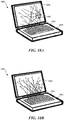
- FIGS 18A-18C illustrate a laptop computer 3D display enabled by the current technology.
- a laptop 1800 includes a light field projector 1801 disposed above the keyboard 1803.
- the light field projector 1801 projects light towards a diffusive screen 1805, which then scatters the light which focuses to form an image 1807 in a space in front of the screen 1805.
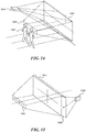
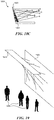
- An immersive virtual reality environment can be constructed according to the current technology as illustrated in Figure 19 .
- Diffusive panels 1901 are on all the walls, and light field projectors 1903 are located in panels overhead.
- the system can project any 3D scene at all into the room via the projectors and diffusive panels, and users 1905 can move freely within the scene.
- the viewing angle of the 3D image depends on the width and position of the panel relative to the 3D image, rather than width and position of the light field projector relative to the 3D image. So, even if the diffusive panel is reflective and the light field projector is behind the viewer, the viewer does not cast any more than a very diffuse shadow on the panel.
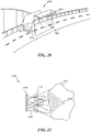
- a vehicle camouflage system 2000 is illustrated in Figure 20 , including diffusive panels 2001 and overhead light field projectors 2003 configured to direct light onto the diffusive panels 2001. It is possible to use the current technology to project arbitrary 3D images using the sides of a vehicle 2005 as diffusive panels 2001 and thereby camouflage the vehicle. If the projected imagery corresponds to the 3D scene behind the vehicle 2005, the vehicle will be effectively invisible.
- flat diffusive panels 2003 are shown for simplicity, however in some embodiments the diffusive panels can be replaced by a complexly curved surface, for example one which follows the contours of the vehicle 2005.
- the current technology is not limited to static projections. By frequently updating the projected image, it is possible to project 3D video. On a larger scale, it is possible to project 3D imagery in a movie theatre.
- An advantage to the 3D images projected by the current system is that the images can be visible with full perspective and parallax from all locations within a viewing volume, as if they were actual 3D objects.
- FIG 21 illustrates an ultrasonic surgery system 2100 in which an ultrasound wavefield projector 2101 produces ultrasonic waves 2103 which, when diffused through the diffusing media 2105 and through the tissue 2107, focus in the focal region 2109, for example at a surgical site.
- the current technology can be used to project an underwater acoustic image which, to unfriendly acoustic sensors, appears to be a real ship, submarine, or obstacle. Similarly, it can be used to project a microwave wave field via reflection from static ground features, such that to unfriendly radar sensors the microwave wave field appears to be a real airplane, vehicle, or other object.
- the current technology can be used to project a visible 3D image via a diffusive surface such as the wall of a building, to give the impression that a person or object is present when not actually present.
- Figure 23 illustrates a light field projector 2301 whose light 2303 is incident on a first diffuser 2305 which scatters and propagates second light wave 2307 toward a second diffuser 2309.
- first diffuser 2305 which scatters and propagates second light wave 2307 toward a second diffuser 2309.
- second light wave 2307 interacts with the second diffuser 2309 both a real image 2311 and a virtual image 2313 are displayed.
- Light field 2303 is a combination of the fields 2311 and 2313.
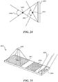
- Figure 24 illustrates the range of viewing angles available for a projected image from a diffuser 2401 at points 2403 and 2405. As illustrated, the image at point 2403 will have a much larger viewing angle 2409 than the viewing angle 2409 associated with the image at point 2405, because point 2403 is closer to the diffuser 2401.
- Figure 25 is an alternative representation of a light field projector element 2500 in a slab-like form factor.
- light 2501 strikes coupler 2503, passes via total-internal reflection through modulator array 2505, and is diffracted by holographic element 2507 to form an image 2509. This is the preferred form factor for eyewear applications.
- Figure 26 represents a user 2601 gazing through one light field projector element 2603 in a near-eye display. Images 2605 and 2607 appear to the user 2601 to be in the far field. Light from light source array 2620 is transmitted through total-internal-reflection waveguide 2615 and shaped by modulator 2610, then enters holographic eyeglass lens element 2603 where it is then diffracted to form images 2605 and 2607.
- Figure 27 illustrates the use of a light field projector 2701 to form an in-focus image 2703 on a non-planar surface 2705. As illustrated, light from the projector 2701 passes through diffuser 2707 and is then focused to the surface 2705 to generate the image 2703.
- the current technology for beam steering when it is desired to direct a light beam, ultrasonic beam, or microwave beam simultaneously to a plurality of targets.
- the "image" formed by the object wave field can be a plurality of point foci, one focus on each target.
- a light pulse a few tens of femtoseconds long only has a longitudinal extent on the order of a micron. If such a pulse spreads widely across a diffuser substantially larger than a micron, the resulting light field will arrive at any given point downstream not as a single pulse but as illumination whose strength and direction of incidence varies widely and rapidly. If the light field is coherent, all of the light simultaneously incident at any point will interfere, but the interference pattern will vary rapidly. If the light field contains multiple light frequencies, the light spectrum at the point will vary rapidly.
- the spatial/temporal shape of the light pulse thus comprises a component pattern for forming arbitrary spatiotemporal pulsed light fields or images in the projection volume.
- the wave or light field projector(s), photodetectors, and/or photosensor arrays can be coupled to a processing unit for controlling the projectors and/or for analyzing the output of the photodetectors or photosensor arrays.
- the processing unit can be a computing device that includes a suitable processor or central processing unit (CPU) that processes data in accordance with computer-readable instructions stored on system memory.
- the CPU for example, can control performance of the various routines described herein and can provide input to control the wave or light field projector.
- the CPU may be any logic processing unit, such as one or more CPUs, digital signal processors (DSPs), application-specific integrated circuits (ASICs), etc.
- the CPU may be a single processing unit or multiple processing units in a device or distributed across multiple devices.
- the CPU is connected to a memory and may be coupled to other hardware devices, for example, with the use of a bus (e.g., a PCI Express or Serial ATA bus).
- the CPU can include, by way of example, a standard personal computer ("PC") or other type of embedded computer running any suitable operating system, such as Linux, Windows, Android, iOS, MAC OS, or an embedded real-time operating system.
- the CPU can be a small form factor PC with integrated hard disk drive (“HDD”) or solid-state drive (“SSD”) and universal serial bus (“USB”) or other ports to communicate with the other components.
- the CPU can include a microprocessor with a standalone motherboard that interfaces with a separate HDD.
- the memory can include read-only memory (ROM) and random access memory (RAM) or other storage devices, such as disk drives or SSDs, that store the executable applications, test software, databases and other software required to, for example, implement the various routines described herein.
- ROM read-only memory
- RAM random access memory
- the processing unit can be connected via hardwired connection to the wave or light field projector, while in other embodiments the processing unit can be remote from the projector.
- a light field projector can easily contain millions of independent elements, so a light field corresponding to one point in the projection volume is typically represented by millions of values.
- To project a given 3D image comprising N points it can be necessary to superimpose N sets of component light fields. This can require manipulating tens to hundreds of billions of numbers, as well as storage and retrieval of all of the requisite component light fields.
- In order to project a 3D video image at full resolution on the order of 30 composite light fields will need to be computed per second.
- Available computer hardware such as a multi-CPU/multi-GPU computer can process tens of thousands of video frames per second.
- Light field refers to the set of light rays in a volume of space. Equivalently, “light field” refers to the set of light wavefronts in a volume of space or passing through a surface and propagating therefrom. In the case of a display, “light field” may consist of a series of light fields which are perceived by the observer as if they, together, are a single light field as in sub-frame projection.
- Wave field refers to the set of wavelengths and propagation vectors of any selected type of wave in a volume of space or passing through a surface and propagating therefrom.
- a wave field projector is any device that projects a wave field of a predetermined type, which can be controlled or specified by a controller.
- a "light field projector” is any device that projects a light field which can be controlled or specified by a controller.
- a light field projector can be one or more coherent or incoherent light sources, projection optics, and a spatial modulator for each light source.
- the spatial modulators can modulate any of phase, amplitude, and/or polarization.
- a light field generator does not necessarily require any lenses.
- the light field projector might be a large phased array of laser diodes, each of which emits a spherical wave.
- it might be an array of liquid crystal elements or deformable mirror elements illuminated by a plane wave of light.
- Many other types of light field generators are available and possible. The present technology does not depend on the type of light field generator used.
- scatterer refers to a wave scatterer. Often, but not always, the term “scatterer” connotes a wave scatterer whose scattering function varies on a very short length scale.
- a light diffuser or a scatterer can be, for example, opal glass, ground glass, a suspension of scattering particles, an array of small lenslets, an array of small prisms, or generally any medium that randomly or quasi-randomly redirects light at each point on the medium.
- Another example of a scatterer is a holographic element.
- a holographic element that converts each of an arbitrary set of point source light fields to a corresponding to specific light field component is herein also referred to as a "holographic diffuser," although that is not what is traditionally meant by "diffuser.”
- waveguide refers to any structure, device, or component whose function is to confine light to a narrow range of paths.
- a waveguide can be an optical fiber which confines light to a plurality of totally reflected modes inside the fiber), a planar waveguide such as a glass plate which confines light to the inside of the plate by total internal reflection at the glass/air interface,
- input coupler means any structure or component that redirects light into a waveguide from a light field external to the waveguide.
- a prism or a bevel at one edge of a glass plate can redirect light from a certain range of incident angles in the air, into totally internally reflected modes within the glass plate and therefore may be an input coupler.
- Another example of an input coupler is a grating or holographic optical element that diffracts externally incident light into totally internally reflected modes internal to a plate.
- output coupler means any structure or component that redirects light incident from totally internally reflected modes in a waveguide, into a light field propagating externally to the waveguide.
- An output coupler is often structurally identical to an input coupler, except that the light propagates in the opposite directions relative to an input coupler and an output coupler.
- three-dimensional image may refer to a non-planar image, a point-cloud, or a planar image in a three-dimensional volume.
- modulator means any device, component, structure or element that, when activated, affects the phase, amplitude, direction, or polarization of light passing through the active region of the device, structure or element in a controllable way.
- modulators transmissive liquid crystal displays, reflective liquid crystal displays, deformable mirrors, electrically or optically controlled absorbers, acousto-optic modulators, electrochromic displays, and micromirror arrays.
- near-eye display means any device whose function is to produce a controllable light field that comprises a virtual image such that when the device is placed at a small distance (typically smaller than about 3 inches) from an eye, the eye perceives the virtual image at a much greater distance (typically in the range from 2 feet to infinity).
- the words “comprise,” “comprising,” and the like are to be construed in an inclusive sense, as opposed to an exclusive or exhaustive sense; that is to say, in the sense of "including, but not limited to.”
- the terms “connected,” “coupled,” or any variant thereof means any connection or coupling, either direct or indirect, between two or more elements; the coupling or connection between the elements can be physical, logical, or a combination thereof.
- the words “herein,” “above,” “below,” and words of similar import, when used in this application refer to this application as a whole and not to any particular portions of this application.
Landscapes
- Physics & Mathematics (AREA)
- General Physics & Mathematics (AREA)
- Optics & Photonics (AREA)
- Engineering & Computer Science (AREA)
- Geometry (AREA)
- Multimedia (AREA)
- Signal Processing (AREA)
- Holo Graphy (AREA)
- Health & Medical Sciences (AREA)
- Biomedical Technology (AREA)
- Nuclear Medicine, Radiotherapy & Molecular Imaging (AREA)
- Radiology & Medical Imaging (AREA)
- Life Sciences & Earth Sciences (AREA)
- Animal Behavior & Ethology (AREA)
- General Health & Medical Sciences (AREA)
- Public Health (AREA)
- Veterinary Medicine (AREA)
- Diffracting Gratings Or Hologram Optical Elements (AREA)
Applications Claiming Priority (3)
| Application Number | Priority Date | Filing Date | Title |
|---|---|---|---|
| US201462031702P | 2014-07-31 | 2014-07-31 | |
| PCT/US2015/043024 WO2016019204A1 (fr) | 2014-07-31 | 2015-07-30 | Projection de champ d'onde et d'image à travers des supports de diffusion |
| EP15827770.7A EP3175293B1 (fr) | 2014-07-31 | 2015-07-30 | Projection de champ d'onde et d'image à travers des supports de diffusion |
Related Parent Applications (2)
| Application Number | Title | Priority Date | Filing Date |
|---|---|---|---|
| EP15827770.7A Division EP3175293B1 (fr) | 2014-07-31 | 2015-07-30 | Projection de champ d'onde et d'image à travers des supports de diffusion |
| EP15827770.7A Division-Into EP3175293B1 (fr) | 2014-07-31 | 2015-07-30 | Projection de champ d'onde et d'image à travers des supports de diffusion |
Publications (1)
| Publication Number | Publication Date |
|---|---|
| EP3663849A1 true EP3663849A1 (fr) | 2020-06-10 |
Family
ID=55181436
Family Applications (2)
| Application Number | Title | Priority Date | Filing Date |
|---|---|---|---|
| EP20154561.3A Pending EP3663849A1 (fr) | 2014-07-31 | 2015-07-30 | Projection d'images et de champs d'onde par l'intermédiaire d'un support diffusif |
| EP15827770.7A Active EP3175293B1 (fr) | 2014-07-31 | 2015-07-30 | Projection de champ d'onde et d'image à travers des supports de diffusion |
Family Applications After (1)
| Application Number | Title | Priority Date | Filing Date |
|---|---|---|---|
| EP15827770.7A Active EP3175293B1 (fr) | 2014-07-31 | 2015-07-30 | Projection de champ d'onde et d'image à travers des supports de diffusion |
Country Status (5)
| Country | Link |
|---|---|
| US (2) | US10321105B2 (fr) |
| EP (2) | EP3663849A1 (fr) |
| JP (3) | JP7156791B2 (fr) |
| CN (2) | CN114236823A (fr) |
| WO (1) | WO2016019204A1 (fr) |
Families Citing this family (53)
| Publication number | Priority date | Publication date | Assignee | Title |
|---|---|---|---|---|
| US10175479B2 (en) * | 2005-11-23 | 2019-01-08 | Fusao Ishii | High contrast projection screen |
| WO2012033171A1 (fr) * | 2010-09-08 | 2012-03-15 | 大日本印刷株式会社 | Dispositif de projection et écran vidéo de type projection |
| US9832855B2 (en) | 2015-10-01 | 2017-11-28 | Asml Netherlands B.V. | Optical isolation module |
| JP6456189B2 (ja) * | 2015-02-27 | 2019-01-23 | 国立研究開発法人情報通信研究機構 | 立体画像表示装置 |
| DE102015117401A1 (de) * | 2015-10-13 | 2017-04-13 | Airbus Operations Gmbh | Flugzeugkabinenanordnung |
| DE102015219859B4 (de) * | 2015-10-13 | 2017-07-27 | Carl Zeiss Vision International Gmbh | Vorrichtung und Verfahren für die AR-Darstellung |
| US10162086B2 (en) | 2016-03-07 | 2018-12-25 | Microsoft Technology Licensing, Llc | Imaging through highly diffusive media with wavefront shaping |
| US9961333B1 (en) | 2016-06-10 | 2018-05-01 | X Development Llc | System and method for light field projection |
| WO2018014045A2 (fr) * | 2016-07-15 | 2018-01-18 | Light Field Lab, Inc. | Procédé d'étalonnage pour des systèmes d'orientation d'énergie holographique |
| US10663657B2 (en) * | 2016-07-15 | 2020-05-26 | Light Field Lab, Inc. | Selective propagation of energy in light field and holographic waveguide arrays |
| US9891516B1 (en) | 2016-08-23 | 2018-02-13 | X Development Llc | Methods for calibrating a light field projection system |
| KR20180040036A (ko) * | 2016-10-11 | 2018-04-19 | 삼성전자주식회사 | 라이트 필드 디스플레이장치 |
| US10444704B2 (en) | 2016-10-21 | 2019-10-15 | Sony Interactive Entertainment Inc. | Dynamic display using holographic recorded pixels |
| US10091496B2 (en) | 2016-11-28 | 2018-10-02 | X Development Llc | Systems, devices, and methods for calibrating a light field projection system |
| US10712567B2 (en) * | 2017-06-15 | 2020-07-14 | Microsoft Technology Licensing, Llc | Holographic display system |
| US11215827B1 (en) * | 2017-06-30 | 2022-01-04 | Snaps Inc. | Eyewear with integrated peripheral display |
| US10084996B1 (en) * | 2017-06-30 | 2018-09-25 | Intel Corporation | Methods and apparatus for controlled shadow casting to increase the perceptual quality of projected content |
| CN109387939B (zh) * | 2017-08-09 | 2021-02-12 | 中强光电股份有限公司 | 近眼式显示装置及其显示影像的校正方法 |
| EP3676973A4 (fr) * | 2017-08-31 | 2021-05-05 | Metalenz, Inc. | Intégration de lentille de métasurface transmissive |
| IL273480B2 (en) * | 2017-09-27 | 2024-03-01 | Magic Leap Inc | Near-eye 3D display with separate phase and amplitude modulators |
| JP6935094B2 (ja) * | 2017-10-04 | 2021-09-15 | ピクシーダストテクノロジーズ株式会社 | フェムト秒レーザを用いて、インタラクティブな空中ボルメトリック画像及び空間オーディオを生成する方法及びシステム |
| JP6945933B2 (ja) * | 2017-12-27 | 2021-10-06 | アルパイン株式会社 | 表示システム |
| US10527557B2 (en) * | 2017-12-29 | 2020-01-07 | Radiant Vision Systems, LLC | Adaptive diffuse illumination systems and methods |
| US11650354B2 (en) | 2018-01-14 | 2023-05-16 | Light Field Lab, Inc. | Systems and methods for rendering data from a 3D environment |
| EP3737977A4 (fr) | 2018-01-14 | 2021-11-10 | Light Field Lab, Inc. | Systèmes de codage optique holographique et diffractif |
| EP3737982B1 (fr) | 2018-01-14 | 2024-01-10 | Light Field Lab, Inc. | Système d'impression tridimensionnel à champ d'énergie |
| US10373391B1 (en) * | 2018-04-23 | 2019-08-06 | AbdurRahman Bin Shahzad Bhatti | Augmented reality system for fitness |
| US11106033B2 (en) * | 2018-07-05 | 2021-08-31 | Magic Leap, Inc. | Waveguide-based illumination for head mounted display system |
| JP7420400B2 (ja) | 2018-07-25 | 2024-01-23 | ライト フィールド ラボ、インコーポレイテッド | ライトフィールドディスプレイシステムベースの遊園地のアトラクション |
| EP3836143A4 (fr) * | 2018-08-09 | 2021-10-27 | Mitsubishi Chemical Corporation | Composition pour support d'enregistrement d'hologramme, et support d'enregistrement d'hologramme |
| WO2020036948A1 (fr) * | 2018-08-14 | 2020-02-20 | Starport Inc. | Système de projection holographique |
| US10607353B2 (en) * | 2018-08-30 | 2020-03-31 | Facebook Technologies, Llc | Structured light depth sensing |
| CN109164583A (zh) * | 2018-11-07 | 2019-01-08 | 深圳珑璟光电技术有限公司 | 一种水下ar装置 |
| EP3912156A1 (fr) * | 2019-01-18 | 2021-11-24 | Dolby Laboratories Licensing Corporation | Détermination de front d'onde d'atténuation pour une réduction de bruit |
| US10942320B2 (en) * | 2019-02-11 | 2021-03-09 | Facebook Technologies, Llc | Dispersion compensation for light coupling through slanted facet of optical waveguide |
| US10904479B2 (en) | 2019-03-12 | 2021-01-26 | Light Field Lab, Inc. | Video communication including holographic content |
| US11212514B2 (en) | 2019-03-25 | 2021-12-28 | Light Field Lab, Inc. | Light field display system for cinemas |
| US11428933B2 (en) | 2019-05-13 | 2022-08-30 | Light Field Lab, Inc. | Light field display system for performance events |
| EP3990571A1 (fr) | 2019-07-31 | 2022-05-04 | SABIC Global Technologies, B.V. | Procédé de craquage catalytique de naphta |
| CN114466916A (zh) | 2019-07-31 | 2022-05-10 | 沙特基础全球技术有限公司 | 石脑油催化裂化方法 |
| US11902500B2 (en) | 2019-08-09 | 2024-02-13 | Light Field Lab, Inc. | Light field display system based digital signage system |
| CN114556193A (zh) * | 2019-08-14 | 2022-05-27 | 阿瓦龙全息照相技术股份公司 | 光场投影仪装置 |
| US20210055551A1 (en) * | 2019-08-23 | 2021-02-25 | Facebook Technologies, Llc | Dispersion compensation in volume bragg grating-based waveguide display |
| CA3148816A1 (fr) | 2019-08-26 | 2021-03-04 | Light Field Lab, Inc. | Systeme d'affichage de champ lumineux pour evenements sportifs |
| JP7354777B2 (ja) * | 2019-11-05 | 2023-10-03 | Dic株式会社 | 高周波装置用液晶化合物 |
| CN111103697B (zh) * | 2020-01-04 | 2021-10-26 | 四川大学 | 利用空间光调制器实现基于相位多样性的散射介质成像 |
| CN111479097B (zh) * | 2020-03-25 | 2022-02-22 | 清华大学 | 基于深度学习的散射透镜成像系统 |
| WO2022119940A1 (fr) * | 2020-12-01 | 2022-06-09 | Looking Glass Factory, Inc. | Système et procédé de traitement d'images tridimensionnelles |
| JP7464023B2 (ja) | 2021-03-11 | 2024-04-09 | カシオ計算機株式会社 | 空間投影装置、空間投影システム及び空間投影方法 |
| CN113917701B (zh) * | 2021-12-14 | 2022-02-18 | 成都工业学院 | 一种投影光场立体显示装置 |
| CN114355623B (zh) * | 2022-03-14 | 2022-05-17 | 成都工业学院 | 一种用于投影光场立体显示的一维逆反射片 |
| US11927769B2 (en) | 2022-03-31 | 2024-03-12 | Metalenz, Inc. | Polarization sorting metasurface microlens array device |
| CN115166994A (zh) * | 2022-06-14 | 2022-10-11 | 北京邮电大学 | 三维显示系统及方法 |
Citations (4)
| Publication number | Priority date | Publication date | Assignee | Title |
|---|---|---|---|---|
| US7352469B2 (en) | 2001-11-06 | 2008-04-01 | Mcgrew Stephen P | Quantum resonance analytical instrument |
| US20080186547A1 (en) * | 2007-02-07 | 2008-08-07 | Konica Minolta Holdings, Inc. | Hologram optical element, method of fabrication thereof, and image display apparatus |
| US20130222384A1 (en) * | 2010-11-08 | 2013-08-29 | Seereal Technologies S.A. | Display device, in particular a head-mounted display, based on temporal and spatial multiplexing of hologram tiles |
| US20140063077A1 (en) | 2012-01-25 | 2014-03-06 | Massachusetts Institute Of Technology | Tensor Displays |
Family Cites Families (23)
| Publication number | Priority date | Publication date | Assignee | Title |
|---|---|---|---|---|
| JPH08507879A (ja) * | 1993-02-26 | 1996-08-20 | イエダ リサーチ アンド デベロツプメント カンパニー リミテツド | ホログラフィー光学装置 |
| EP0995319B1 (fr) | 1997-07-15 | 2003-05-28 | Thomson Multimedia Inc. | Recepteurs de television a projection holographique avec correction optique |
| US6175431B1 (en) | 1999-07-09 | 2001-01-16 | Digilens, Inc. | Projection systems based on reconfigurable holographic optics |
| US7660024B2 (en) * | 2000-08-07 | 2010-02-09 | Physical Optics Corporation | 3-D HLCD system and method of making |
| GB0108838D0 (en) * | 2001-04-07 | 2001-05-30 | Cambridge 3D Display Ltd | Far field display |
| JP4313102B2 (ja) | 2003-06-27 | 2009-08-12 | 凸版印刷株式会社 | 立体像表示装置 |
| JP2005122814A (ja) * | 2003-10-16 | 2005-05-12 | Sony Corp | ホログラム記録再生装置、ホログラム記録再生方法、位相アドレスコード作成方法及び位相アドレスコード作成プログラム |
| JP2005127651A (ja) * | 2003-10-27 | 2005-05-19 | Mitsubishi Heavy Ind Ltd | 表示システム |
| TWI243960B (en) * | 2004-06-25 | 2005-11-21 | Ind Tech Res Inst | The autostereoscopic projection screen |
| US20090009834A1 (en) * | 2006-10-06 | 2009-01-08 | California Institute Of Technology | Optical phase processing in a scattering medium |
| US8139103B2 (en) * | 2006-11-11 | 2012-03-20 | Vuzix Corporation | Traveling lens for video display |
| WO2010062481A1 (fr) * | 2008-11-02 | 2010-06-03 | David Chaum | Système et appareil d'affichage proche de l'oeil |
| US20110032587A1 (en) | 2009-03-20 | 2011-02-10 | Absolute Imaging LLC | System and Method for Autostereoscopic Imaging |
| US20100238529A1 (en) * | 2009-03-23 | 2010-09-23 | Qualcomm Mems Technologies, Inc. | Dithered holographic frontlight |
| CN101539515B (zh) * | 2009-04-29 | 2010-12-29 | 华南师范大学 | 一种光声内窥成像方法及其装置 |
| US9057695B2 (en) | 2009-09-24 | 2015-06-16 | Canon Kabushiki Kaisha | Apparatus and method for irradiating a scattering medium with a reconstructive wave |
| US8472120B2 (en) * | 2010-02-28 | 2013-06-25 | Osterhout Group, Inc. | See-through near-eye display glasses with a small scale image source |
| CN103946732B (zh) * | 2011-09-26 | 2019-06-14 | 微软技术许可有限责任公司 | 基于对透视、近眼显示器的传感器输入的视频显示修改 |
| US8773599B2 (en) * | 2011-10-24 | 2014-07-08 | Google Inc. | Near-to-eye display with diffraction grating that bends and focuses light |
| CN104160697B (zh) * | 2012-03-13 | 2018-01-26 | 索尼公司 | 头戴式显示器 |
| TW201426014A (zh) | 2012-12-28 | 2014-07-01 | Ind Tech Res Inst | 立體顯示系統 |
| US9354605B2 (en) * | 2014-02-21 | 2016-05-31 | Korea Advanced Institute Of Science And Technology | Apparatus and method for forming 3-dimensional holographic image using scattering layer |
| US9335549B2 (en) * | 2014-03-19 | 2016-05-10 | Google Inc. | Imaging lightguide with holographic boundaries |
-
2015
- 2015-07-30 CN CN202111393208.0A patent/CN114236823A/zh active Pending
- 2015-07-30 EP EP20154561.3A patent/EP3663849A1/fr active Pending
- 2015-07-30 WO PCT/US2015/043024 patent/WO2016019204A1/fr active Application Filing
- 2015-07-30 EP EP15827770.7A patent/EP3175293B1/fr active Active
- 2015-07-30 CN CN201580050263.6A patent/CN106716227B/zh active Active
- 2015-07-30 JP JP2017526476A patent/JP7156791B2/ja active Active
- 2015-07-30 US US14/814,443 patent/US10321105B2/en active Active
-
2019
- 2019-05-03 US US16/403,249 patent/US11418764B2/en active Active
- 2019-11-20 JP JP2019209850A patent/JP2020038388A/ja active Pending
-
2021
- 2021-12-03 JP JP2021197008A patent/JP2022037042A/ja active Pending
Patent Citations (4)
| Publication number | Priority date | Publication date | Assignee | Title |
|---|---|---|---|---|
| US7352469B2 (en) | 2001-11-06 | 2008-04-01 | Mcgrew Stephen P | Quantum resonance analytical instrument |
| US20080186547A1 (en) * | 2007-02-07 | 2008-08-07 | Konica Minolta Holdings, Inc. | Hologram optical element, method of fabrication thereof, and image display apparatus |
| US20130222384A1 (en) * | 2010-11-08 | 2013-08-29 | Seereal Technologies S.A. | Display device, in particular a head-mounted display, based on temporal and spatial multiplexing of hologram tiles |
| US20140063077A1 (en) | 2012-01-25 | 2014-03-06 | Massachusetts Institute Of Technology | Tensor Displays |
Non-Patent Citations (5)
| Title |
|---|
| "Focusing coherent light through opaque strongly scattering media", OPTICS LETTERS, vol. 32, no. 16, 15 August 2007 (2007-08-15) |
| "Scattering lens resolves sub-100 nm structures with visible light", PHYSICAL REVIEW LETTERS 193905, May 2011 (2011-05-01) |
| CHAIGNE ET AL.: "Controlling light in scattering media non-invasively using the photoacoustic transmission matrix", NATURE PHOTONICS, vol. 8, 2014, pages 58 - 64 |
| FELLNERHANSEN: "Toward the Light Field Display: Autostereoscopic Rendering via a Cluster of Projectors", EUROGRAPHICS, 2006 |
| I. M.VALLEKOOP: "Exploiting disorder for perfect focusing", ARXIV:0910.0873V1 [PHYSICS.OPTICS, vol. 5, October 2009 (2009-10-01) |
Also Published As
| Publication number | Publication date |
|---|---|
| EP3175293A1 (fr) | 2017-06-07 |
| US20160037146A1 (en) | 2016-02-04 |
| US20190260977A1 (en) | 2019-08-22 |
| JP2017526017A (ja) | 2017-09-07 |
| US11418764B2 (en) | 2022-08-16 |
| CN106716227B (zh) | 2021-12-10 |
| JP2022037042A (ja) | 2022-03-08 |
| WO2016019204A1 (fr) | 2016-02-04 |
| US10321105B2 (en) | 2019-06-11 |
| EP3175293A4 (fr) | 2018-04-11 |
| CN106716227A (zh) | 2017-05-24 |
| CN114236823A (zh) | 2022-03-25 |
| JP2020038388A (ja) | 2020-03-12 |
| JP7156791B2 (ja) | 2022-10-19 |
| EP3175293B1 (fr) | 2020-11-04 |
Similar Documents
| Publication | Publication Date | Title |
|---|---|---|
| US11418764B2 (en) | Image and wave field projection through diffusive media | |
| US20230350208A1 (en) | Light homogenization | |
| JP7175416B2 (ja) | 厚い媒体を含む仮想現実、拡張現実、および複合現実システムならびに関連方法 | |
| US20210311260A1 (en) | Ducted pupil expansion | |
| US8582206B2 (en) | Laser-scanning virtual image display | |
| JP5060704B2 (ja) | 平面型投影ディスプレイ | |
| JP2015528919A (ja) | 導波路リフレクタアレイプロジェクタを用いる複数の深度平面3次元ディスプレイ | |
| US11022799B2 (en) | Projector-combiner display with beam replication | |
| EP3792681B1 (fr) | Appareil d'affichage multi-images utilisant une projection holographique | |
| EP3707548A1 (fr) | Système optique à compensation de dispersion | |
| TW202136836A (zh) | 光瞳擴展 | |
| US10527773B2 (en) | Backlight unit for holographic display apparatus and holographic display apparatus including the same | |
| KR102095088B1 (ko) | 비주기적으로 설계된 광학 소자를 이용하여 3차원 홀로그래픽 영상을 형성하는 장치 및 방법 | |
| WO2017128730A1 (fr) | Dispositif d'affichage holographique et procédé d'affichage holographique | |
| KR20230156259A (ko) | 헤드-업 디스플레이 | |
| JP2023046260A (ja) | 瞳拡張器の完全性 |
Legal Events
| Date | Code | Title | Description |
|---|---|---|---|
| PUAI | Public reference made under article 153(3) epc to a published international application that has entered the european phase |
Free format text: ORIGINAL CODE: 0009012 |
|
| STAA | Information on the status of an ep patent application or granted ep patent |
Free format text: STATUS: THE APPLICATION HAS BEEN PUBLISHED |
|
| AC | Divisional application: reference to earlier application |
Ref document number: 3175293 Country of ref document: EP Kind code of ref document: P |
|
| AK | Designated contracting states |
Kind code of ref document: A1 Designated state(s): AL AT BE BG CH CY CZ DE DK EE ES FI FR GB GR HR HU IE IS IT LI LT LU LV MC MK MT NL NO PL PT RO RS SE SI SK SM TR |
|
| STAA | Information on the status of an ep patent application or granted ep patent |
Free format text: STATUS: REQUEST FOR EXAMINATION WAS MADE |
|
| 17P | Request for examination filed |
Effective date: 20201210 |
|
| RBV | Designated contracting states (corrected) |
Designated state(s): AL AT BE BG CH CY CZ DE DK EE ES FI FR GB GR HR HU IE IS IT LI LT LU LV MC MK MT NL NO PL PT RO RS SE SI SK SM TR |
|
| STAA | Information on the status of an ep patent application or granted ep patent |
Free format text: STATUS: EXAMINATION IS IN PROGRESS |
|
| 17Q | First examination report despatched |
Effective date: 20220407 |
|
| P01 | Opt-out of the competence of the unified patent court (upc) registered |
Effective date: 20230530 |