EP3663628B1 - Device for fixing a camera system to moving objects - Google Patents
Device for fixing a camera system to moving objects Download PDFInfo
- Publication number
- EP3663628B1 EP3663628B1 EP19000537.1A EP19000537A EP3663628B1 EP 3663628 B1 EP3663628 B1 EP 3663628B1 EP 19000537 A EP19000537 A EP 19000537A EP 3663628 B1 EP3663628 B1 EP 3663628B1
- Authority
- EP
- European Patent Office
- Prior art keywords
- eddy current
- current brake
- slide
- bridge
- shaped
- Prior art date
- Legal status (The legal status is an assumption and is not a legal conclusion. Google has not performed a legal analysis and makes no representation as to the accuracy of the status listed.)
- Active
Links
- 238000013016 damping Methods 0.000 claims description 8
- 125000006850 spacer group Chemical group 0.000 description 12
- 238000010276 construction Methods 0.000 description 7
- 238000004519 manufacturing process Methods 0.000 description 3
- 230000006641 stabilisation Effects 0.000 description 2
- 238000011105 stabilization Methods 0.000 description 2
- 241001295925 Gegenes Species 0.000 description 1
- 239000006096 absorbing agent Substances 0.000 description 1
- 238000006073 displacement reaction Methods 0.000 description 1
- 238000005516 engineering process Methods 0.000 description 1
- 238000000034 method Methods 0.000 description 1
- 230000035515 penetration Effects 0.000 description 1
- 230000035939 shock Effects 0.000 description 1
- 239000000725 suspension Substances 0.000 description 1
- XLYOFNOQVPJJNP-UHFFFAOYSA-N water Substances O XLYOFNOQVPJJNP-UHFFFAOYSA-N 0.000 description 1
Images


Classifications
-
- F—MECHANICAL ENGINEERING; LIGHTING; HEATING; WEAPONS; BLASTING
- F16—ENGINEERING ELEMENTS AND UNITS; GENERAL MEASURES FOR PRODUCING AND MAINTAINING EFFECTIVE FUNCTIONING OF MACHINES OR INSTALLATIONS; THERMAL INSULATION IN GENERAL
- F16M—FRAMES, CASINGS OR BEDS OF ENGINES, MACHINES OR APPARATUS, NOT SPECIFIC TO ENGINES, MACHINES OR APPARATUS PROVIDED FOR ELSEWHERE; STANDS; SUPPORTS
- F16M13/00—Other supports for positioning apparatus or articles; Means for steadying hand-held apparatus or articles
- F16M13/02—Other supports for positioning apparatus or articles; Means for steadying hand-held apparatus or articles for supporting on, or attaching to, an object, e.g. tree, gate, window-frame, cycle
-
- F—MECHANICAL ENGINEERING; LIGHTING; HEATING; WEAPONS; BLASTING
- F16—ENGINEERING ELEMENTS AND UNITS; GENERAL MEASURES FOR PRODUCING AND MAINTAINING EFFECTIVE FUNCTIONING OF MACHINES OR INSTALLATIONS; THERMAL INSULATION IN GENERAL
- F16M—FRAMES, CASINGS OR BEDS OF ENGINES, MACHINES OR APPARATUS, NOT SPECIFIC TO ENGINES, MACHINES OR APPARATUS PROVIDED FOR ELSEWHERE; STANDS; SUPPORTS
- F16M11/00—Stands or trestles as supports for apparatus or articles placed thereon Stands for scientific apparatus such as gravitational force meters
- F16M11/02—Heads
- F16M11/04—Means for attachment of apparatus; Means allowing adjustment of the apparatus relatively to the stand
- F16M11/043—Allowing translations
- F16M11/046—Allowing translations adapted to upward-downward translation movement
-
- F—MECHANICAL ENGINEERING; LIGHTING; HEATING; WEAPONS; BLASTING
- F16—ENGINEERING ELEMENTS AND UNITS; GENERAL MEASURES FOR PRODUCING AND MAINTAINING EFFECTIVE FUNCTIONING OF MACHINES OR INSTALLATIONS; THERMAL INSULATION IN GENERAL
- F16M—FRAMES, CASINGS OR BEDS OF ENGINES, MACHINES OR APPARATUS, NOT SPECIFIC TO ENGINES, MACHINES OR APPARATUS PROVIDED FOR ELSEWHERE; STANDS; SUPPORTS
- F16M11/00—Stands or trestles as supports for apparatus or articles placed thereon Stands for scientific apparatus such as gravitational force meters
- F16M11/02—Heads
- F16M11/04—Means for attachment of apparatus; Means allowing adjustment of the apparatus relatively to the stand
- F16M11/043—Allowing translations
- F16M11/048—Allowing translations adapted to forward-backward translation movement
-
- G—PHYSICS
- G03—PHOTOGRAPHY; CINEMATOGRAPHY; ANALOGOUS TECHNIQUES USING WAVES OTHER THAN OPTICAL WAVES; ELECTROGRAPHY; HOLOGRAPHY
- G03B—APPARATUS OR ARRANGEMENTS FOR TAKING PHOTOGRAPHS OR FOR PROJECTING OR VIEWING THEM; APPARATUS OR ARRANGEMENTS EMPLOYING ANALOGOUS TECHNIQUES USING WAVES OTHER THAN OPTICAL WAVES; ACCESSORIES THEREFOR
- G03B17/00—Details of cameras or camera bodies; Accessories therefor
- G03B17/56—Accessories
- G03B17/561—Support related camera accessories
-
- F—MECHANICAL ENGINEERING; LIGHTING; HEATING; WEAPONS; BLASTING
- F16—ENGINEERING ELEMENTS AND UNITS; GENERAL MEASURES FOR PRODUCING AND MAINTAINING EFFECTIVE FUNCTIONING OF MACHINES OR INSTALLATIONS; THERMAL INSULATION IN GENERAL
- F16M—FRAMES, CASINGS OR BEDS OF ENGINES, MACHINES OR APPARATUS, NOT SPECIFIC TO ENGINES, MACHINES OR APPARATUS PROVIDED FOR ELSEWHERE; STANDS; SUPPORTS
- F16M2200/00—Details of stands or supports
- F16M2200/04—Balancing means
- F16M2200/041—Balancing means for balancing rotational movement of the head
-
- F—MECHANICAL ENGINEERING; LIGHTING; HEATING; WEAPONS; BLASTING
- F16—ENGINEERING ELEMENTS AND UNITS; GENERAL MEASURES FOR PRODUCING AND MAINTAINING EFFECTIVE FUNCTIONING OF MACHINES OR INSTALLATIONS; THERMAL INSULATION IN GENERAL
- F16M—FRAMES, CASINGS OR BEDS OF ENGINES, MACHINES OR APPARATUS, NOT SPECIFIC TO ENGINES, MACHINES OR APPARATUS PROVIDED FOR ELSEWHERE; STANDS; SUPPORTS
- F16M2200/00—Details of stands or supports
- F16M2200/06—Arms
- F16M2200/063—Parallelogram arms
-
- F—MECHANICAL ENGINEERING; LIGHTING; HEATING; WEAPONS; BLASTING
- F16—ENGINEERING ELEMENTS AND UNITS; GENERAL MEASURES FOR PRODUCING AND MAINTAINING EFFECTIVE FUNCTIONING OF MACHINES OR INSTALLATIONS; THERMAL INSULATION IN GENERAL
- F16M—FRAMES, CASINGS OR BEDS OF ENGINES, MACHINES OR APPARATUS, NOT SPECIFIC TO ENGINES, MACHINES OR APPARATUS PROVIDED FOR ELSEWHERE; STANDS; SUPPORTS
- F16M2200/00—Details of stands or supports
- F16M2200/06—Arms
- F16M2200/065—Arms with a special structure, e.g. reinforced or adapted for space reduction
Definitions
- the invention relates to a device for holding a camera system, preferably a holding device for attaching the camera system to moving objects, the holding device being attached to the moving objects as a damping element.
- a pan and nod function is a known state of the art (for example EP3176489A1 ).
- the inclusion of a third axis (roll axis) is also known, but requires a high technical effort for the production and operation of such devices.
- the pivoting of the mounting systems including the cameras can be carried out manually as well as by means of various motor drives.
- stepper motors are used for this, which are used via a rotary shaft and a control circuit to control the pan / tilt function.
- pulse counters is also to be regarded as known.
- the DE 102 08 413 B4 describes a pivotable tripod head for a camera, which can be pivoted about at least one axis with the aid of a motor drive and has a receptacle for the camera, the tripod head being composed of elements of a kit, namely motor drive modules with a motor housing and an output shaft and the motor housing fastening devices for Has connection of the motor housing with a further element. Rigid straight bars with clamping elements are used.
- a camera holder for vehicles with vibration damping is also known, whereby one or more gas or oil pressure shock absorbers with springs or spring elements for vibration damping are arranged in a hinge-shaped holder opposite a hinge pivot point ( DE 20 2013 007 276 U1 ).
- a camera holder used in Hollywood studios is known, which is attached to a camera in a multi-articulated manner via an upper receptacle.
- the DE 10 2006 014 441 B4 describes an adjustment device that can be used for remote or direct adjustment of units such as light sources or cameras.
- the EP 2 416 202 A1 describes a camera stabilization system with a 360 ° rotation axis.
- a camera head which has a support arm with a vertical rotating device, a downwardly open U-shaped receptacle being attached to the rotating device, which has a pivoting device on its side arms, which is also U-shaped and on its horizontal Connecting bar has a moveable camera mount.
- the EP 2 759 480 A1 describes a two-axis and a three-axis ball head for use in a small unmanned aerial vehicle, in particular a helicopter. Both embodiments have a machine frame arrangement with different frames which are guided or engage in one another.
- a camera mount is arranged in the inner frame, which allows the mini camera (GoPro) to be tilted vertically via a U-shaped mount (bracket). It is not possible to adjust the mini camera horizontally.
- another bracket is centrally arranged as a cantilever arm, which can perform a rotary movement.
- a fourth holder At the other end of the Kargarms there is a fourth holder, which in turn is U-shaped and allows further rotation. With this bracket, the device is attached to the aircraft. Overall, the entire device has three drives.
- the device is unsuitable for high-speed recordings because it does not have any shake protection.
- Only a mini camera (GoPro) can be used as camera technology and not a professional high-speed camera.
- the entire lightweight construction is preferably designed for use in mini helicopters (drones).
- a closed double cage design is implemented.
- US 2010/0079101 A1 describes a camera mount that can be attached to an car and has a stabilization system.
- the device is preferably designed as an open tilt-turn device, in the upper U-shaped holder of which a camera is guided over a dovetail-shaped receptacle. It is therefore designed as an open triple frame construction.
- the dovetail-shaped camera mount is supported by a central tilt joint on the horizontal leg of the upper U-shaped frame and can be tilted sideways to a limited extent. Furthermore, an embodiment is described which has a triple frame. This embodiment also does not have any effective anti-shake protection for high-speed recordings. It is just a simple holding device for amateur video recordings without a professional background.
- the EP 0 966 154 A1 describes a method and an equipment for three-axis moveable recordings. In this sense, it is a three-axis remote control system for a camera with a joystick as a control element and a data line to the camera. Below the camera - between this and the camera stand - there is a camera guide that can be moved in three axes, with each direction of movement being reached via a toothed / V-belt drive. This device, which is not protected against shaking, is also completely unsuitable for professional high-speed recordings.
- the invention is based on the object of providing a holder for preferably moving camera recordings that can be securely and easily attached to moving objects and that enables very good, low-vibration recording quality even at high speeds and in the off-road area.
- the lower part of the eddy current brake is suspended from the slide via a bracket, the suspension being angled.
- control and at least one drive are attached to the lower part of the at least one eddy current brake on its underbody area, so that both parts of the eddy current brake are guided into one another so that they can be adjusted in height and length.
- the at least one spring is designed to be adjustable via a spindle or the like. By adjusting the spring, which can be designed as a spiral or gas pressure spring, it is ensured that the optimal working range of the bracket is reached exactly in a horizontal position.
- the horizontal fine-tuning and soft damping of the camera system is carried out via the control by changing the penetration depth and the longitudinal displacement of the two parts of the magnets on the slide.
- the magnetic field is shielded by means of shielding plates arranged on both sides of the outside of the eddy current brake, so that sensitive devices (cell phones) cannot be damaged.
- the cantilever arm is designed to be rotatable so that the camera system can be attached either to the top of the horizontal part of the cantilever arm or to the underside of the horizontal part of the cantilever arm.
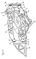
- the device for holding a camera system on moving objects has a base body 1 designed as a double parallelogram, which is made up of two brackets 2; 3 and 4; 5 and from the two bridge-shaped spacers 8; 9 composed, the bracket 2; 3; 4; 5 on both spacers 8; 9 via the swivel joints 10; 11; 12; 13; 14; 15; 16; 17 are movably attached ( Figure 1 , 2 , 3 ).
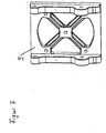
- the rotatable cantilever arm 25 for attaching the camera system is attached to the spacer 9 and devices for attachment to a vehicle are attached to the spacer 8 ( Figure 6 , 7th , 8th ).
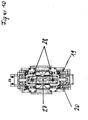
- brackets 2; 3; 4; 5 are mounted diagonally to support the carriage 18, which supports the guides 19; 20 has, on which the two parts 23; 24 of the eddy current brake 22 can move longitudinally ( Figure 4 , 5 ).
- the lower part 24 of the eddy current brake 22 is suspended from the bracket 26 so that it can be adjusted higher.
- the spring (s) 21 clamped in the longitudinal direction in the upper area of the slide 18 ensure via a spindle-shaped adjustment that the entire holder with the camera system is in a horizontal position without the eddy current brake 22 being switched on.
- the controller 27 and at least one drive 28 are attached to the bracket 26 of the lower part 24 of the eddy current brake 22 ( Figure 10 ).
- the control 27 and the drive 28 ensure that the longitudinal adjustment of the carriage 18 on the guides 19; 20 as well as the height adjustment of the lower part 24 of the eddy current brake 22 in the upper part 23 of the eddy current brake 22 in or out, a fine-tuning of the entire bracket including the camera system in the horizontal can take place when the vehicle moves on any surface.
Description
Die Erfindung betrifft eine Vorrichtung zur Halterung eines Kamerasystems, vorzugsweise einer Halterung zur Anbringung des Kamerasystems an bewegten Objekten, wobei die Halterung als Dämpfungselement an den bewegten Objekten befestigt ist.The invention relates to a device for holding a camera system, preferably a holding device for attaching the camera system to moving objects, the holding device being attached to the moving objects as a damping element.
Für das Herstellen von Film-, Fernseh-, Video- oder Werbeaufnahmen ist es notwendig, die verwendeten Kameras auf Halterungen oder Stativköpfen zu befestigen, die in mehreren Achsen verschwenkbar sind.For the production of film, television, video or advertising recordings, it is necessary to attach the cameras used to brackets or tripod heads that can be pivoted in several axes.
Eine Schwenk- und Nickfunktion ist dabei ein bekannter Stand der Technik (zum Beispiel
Das Verschwenken der Halterungssysteme inklusive der Kameras kann dabei manuell als auch mittels verschiedener Motorantriebe durchgeführt werden. Üblicherweise werden hierfür Schrittmotoren verwendet, die über eine Rotationswelle und eine Steuerschaltung zum Steuern der Schwenk-/Kippfunktion verwendet werden. Das Verwenden von Impulszählern ist ebenfalls als bekannt anzusehen.The pivoting of the mounting systems including the cameras can be carried out manually as well as by means of various motor drives. Usually, stepper motors are used for this, which are used via a rotary shaft and a control circuit to control the pan / tilt function. The use of pulse counters is also to be regarded as known.
Aus der
Die
Ebenfalls bekannt ist ein Kamerahalter für Fahrzeuge mit einer Vibrationsdämpfung, wobei ein oder mehrere Gas- oder Öldruckstoßdämpfer mit Federn oder Federelementen zur Vibrationsdämpfung in einem scharnierförmigen Halter gegenüber einem Scharnierdrehpunkt angeordnet sind (
Die
Sie weist zwei Schwenkachsen und zwei Motoreinheiten mit Microschrittmotoren auf und ist getriebelos aufgebaut.It has two swivel axes and two motor units with micro step motors and is gearless.
Die
Aus der
Die
Die Vorrichtung ist für High-Speed-Aufnahmen ungeeignet, da sie über keinen Verwackelschutz verfügt. Als Kameratechnik ist nur eine Mini-Kamera (GoPro) einsetzbar und keine professionelle High-Speed-Kamera. Die gesamte Leichtbau-Konstruktion ist vorzugsweise auf die Verwendung in Mini-Helikoptern (Drohnen) ausgelegt. Eine geschlossene Doppelkäfig-Ausführung ist realisiert. In der
Die
Alle bekannten Kamerahalterungen weisen folgende Nachteile auf:
- 1. Eine dreidimensionale Beweglichkeit ist entweder gar nicht oder nur technisch sehr aufwendig und teuer realisierbar.
- 2. Es entstehen Vibrationen an der Halterung, die die Kamera und damit die Aufnahmequalität erheblich beeinflussen.
- 3. Aufgrund der technisch aufwendigen Konstruktionen sind die Halterungen nur mit großem Aufwand zu transportieren und zusätzlich empfindlich gegen Transportschäden.
- 4. Es sind teure Versicherungen notwendig.
- 5. Aufgrund der hohen Herstellungskosten existieren nur eine sehr begrenzte Anzahl an derartigen Halterungen, die teuer gekauft oder geleast werden müssen.
- 6. Die meisten Halterungen sind nicht oder nur bedingt und aufwendig an Fahrzeugen oder Flugkörpern oder Booten anzubringen und erfüllen dann in unzureichender Art die notwendigen Anforderungen zur sicheren Befestigung.
- 7. Die bekannten professionellen Halterungen für bewegliche Aufnahmen weisen ein sehr hohes Eigengewicht auf.
- 8. Die bekannten Halterungen weisen nicht die gleiche Stabilität, eine unzureichende Vibrations- und Schwingungsdämpfung sowie ungenügende flexiblen Anbringungsmöglichkeiten auf.
- 1. A three-dimensional mobility is either not possible at all or only technically very complex and expensive.
- 2. There are vibrations on the bracket that have a significant impact on the camera and thus the recording quality.
- 3. Due to the technically complex constructions, the brackets can only be transported with great effort and are also sensitive to transport damage.
- 4. Expensive insurance is necessary.
- 5. Because of the high manufacturing costs, there are only a very limited number of such holders, which have to be bought or leased at great expense.
- 6. Most of the brackets cannot be attached to vehicles, missiles or boats, or only to a limited extent and at great expense then insufficiently the necessary requirements for secure fastening.
- 7. The well-known professional mounts for movable recordings have a very high dead weight.
- 8. The known brackets do not have the same stability, insufficient vibration and vibration damping and insufficient flexible mounting options.
Der Erfindung liegt die Aufgabe zugrunde, eine Halterung für vorzugsweise bewegliche Kameraaufnahmen bereitzustellen, die sicher und einfach an beweglichen Objekten zu befestigen ist und auch bei hohen Geschwindigkeiten sowie im Off-Road-Bereich, eine sehr gute vibrationsarme Aufnahmequalität ermöglicht.The invention is based on the object of providing a holder for preferably moving camera recordings that can be securely and easily attached to moving objects and that enables very good, low-vibration recording quality even at high speeds and in the off-road area.
Die Erfindung löst die Aufgabe dadurch, dass
die Halterung einen als doppeltes Parallelogramm ausgeführten Grundkörper aufweist,
- wobei der Grundkörper an seinen beiden Seiten jeweils zwei seitliche Bügel besitzt, zwischen denen diagonal zwei Wellen und an den jeweiligen Enden der Bügel zwei brückenförmig ausgebildete Abstandshalter angeordnet sind und die seitlichen Bügel an beiden Abstandshaltern jeweils über Drehgelenke befestigt sind,
- wobei zwischen zwei Drehgelenken der Abstandshalter ein an den Wellen diagonal gelenkig angeordneter Schlitten befestigt ist, der auf Führungen zwischen den brückenförmigen Abstandshaltern längsbeweglich ausgeführt ist und neben der mindestens einen Feder mindestens eine zweigeteilte Wirbelstrombremse aufweist, deren beide Teile gleitend ineinander geführt sind,
- wobei an einem der brückenförmigen Abstandshalter eine Befestigung zur Fixierung am beweglichen Objekt und am anderen der brückenförmigen Abstandshalter ein Kragarm zur Aufnahme des Kamerasystems angeordnet ist.
the holder has a basic body designed as a double parallelogram,
- The base body has two lateral brackets on each of its two sides, between which two shafts are arranged diagonally and two bridge-shaped spacers are arranged at the respective ends of the brackets and the lateral brackets are fastened to both spacers via swivel joints,
- wherein between two swivel joints of the spacers a slide is mounted diagonally articulated on the shafts, which is designed to be longitudinally movable on guides between the bridge-shaped spacers and, in addition to the at least one spring, has at least one two-part eddy current brake, the two parts of which are slid into one another
- wherein a fastening for fixation on the moving object is arranged on one of the bridge-shaped spacers and a cantilever arm for receiving the camera system is arranged on the other of the bridge-shaped spacers.
Der untere Teil der Wirbelstrombremse ist dabei am Schlitten über eine Halterung abgehangen, wobei die Abhängung abgewinkelt ausgeführt ist.The lower part of the eddy current brake is suspended from the slide via a bracket, the suspension being angled.
Am unteren Teil der mindestens einen Wirbelstrombremse sind an deren Unterbodenbereich die Steuerung und mindestens ein Antrieb befestigt, sodass beide Teile der Wirbelstrombremse höhen- und längsverstellbar gleitend ineinander geführt sind.The control and at least one drive are attached to the lower part of the at least one eddy current brake on its underbody area, so that both parts of the eddy current brake are guided into one another so that they can be adjusted in height and length.
Die mindestens eine Feder ist über eine Spindel oder dergleichen einstellbar ausgeführt ist. Durch die Verstellung der Feder, die als Spiral- oder Gasdruckfeder ausgeführt sein kann, wird abgesichert, dass der optimale Arbeitsbereich der Halterung exakt in einer waagerechten Position erreicht wird.The at least one spring is designed to be adjustable via a spindle or the like. By adjusting the spring, which can be designed as a spiral or gas pressure spring, it is ensured that the optimal working range of the bracket is reached exactly in a horizontal position.
Im bewegten Zustand und auf verschiedenen Untergründen erfolgt das waagerechte Feintuning und eine weiche Dämpfung des Kamerasystems über die Steuerung durch eine Veränderung der Eindringtiefe und der Längsverschiebung der beiden Teile der Magneten am Schlitten.In the moving state and on different surfaces, the horizontal fine-tuning and soft damping of the camera system is carried out via the control by changing the penetration depth and the longitudinal displacement of the two parts of the magnets on the slide.
Mittels beidseitig an den Außenseiten der Wirbelstrombremse angeordneter Abschirmplatten erfolgt eine Abschirmung des Magnetfeldes, sodass empfindliche Geräte (Handys) keinen Schaden nehmen können.The magnetic field is shielded by means of shielding plates arranged on both sides of the outside of the eddy current brake, so that sensitive devices (cell phones) cannot be damaged.
Der Kragarm ist drehbar ausgeführt, sodass das Kamerasystem entweder auf der Oberseite des waagerechten Teils des Kragarms oder auf der Unterseite des waagerechten Teils des Kragarms befestigt werden kann.The cantilever arm is designed to be rotatable so that the camera system can be attached either to the top of the horizontal part of the cantilever arm or to the underside of the horizontal part of the cantilever arm.
- durch die erfindungsgemäße Konstruktion des Grundkörpers der Halterung als doppeltes Parallelogramm in käfigartiger Ausführung, ist es möglich, ein Dämpfungssystem in dessen Inneren anzuordnen, wodurch die gesamte Konstruktion mehrfach gelenkig jede Bewegung des Kamerasystems auf jedem Untergrund sowie bei wechselnden Geschwindigkeiten ausschwingen kannDue to the inventive construction of the base body of the bracket as a double parallelogram in a cage-like design, it is possible to arrange a damping system inside, whereby the entire construction can swing out multiple articulated movements of the camera system on any surface and at changing speeds
- die erfindungsgemäße Anbringung des Schlittens auf zwei zwischen den jeweiligen beiden seitlichen Bügeln diagonal angeordneten Wellen gewährleistet, dass der zweigeteilte Schlitten längsverschieblich ausgeführt werden kannthe attachment of the slide according to the invention on two shafts arranged diagonally between the respective two lateral brackets ensures that the two-part slide can be designed to be longitudinally displaceable
- mittels der einstellbaren Federn kann das Kamerasystem an der Halterung exakt waagerecht ausgerichtet und federnd gelagert werdenBy means of the adjustable springs, the camera system can be aligned exactly horizontally on the bracket and be resiliently mounted
- die zweigeteilte Ausführung der Wirbelstrombremse auf zwei längs- und höhenbeweglichen Schlittenteilen gewährleistet, dass die Magneten gleitend ineinander geführt werden könnenThe two-part design of the eddy current brake on two longitudinally and vertically movable slide parts ensures that the magnets can slide into one another
- durch die erfindungsgemäße Steuerung wird abgesichert, dass in kürzester Zeit eine der jeweiligen Gegebenheit angepasste Dämpfung der Konstruktion in den waagerechten Arbeitsbereich erfolgen kann, indem die Magneten der Wirbelstrombremse sich entweder tiefer oder weniger tief und längsverschieblich auf den Führungen des Schlittens ineinander bewegen können, sodass ein Feintuning stattfindetThe control according to the invention ensures that in the shortest possible time a damping of the construction adapted to the respective situation can take place in the horizontal working area, in that the magnets of the eddy current brake can move either deeper or less deep and longitudinally displaceable on the guides of the slide so that a Fine tuning takes place
- die Aufnahmequalität des Kamerasystems ist durch die erfindungsgemäße Lösung extrem verwackel- sowie schwingungs- und vibrationsfreithe recording quality of the camera system is extremely blurring and vibration and vibration-free due to the solution according to the invention
- das Kamerasystem ist dabei nach einer kaum wahrnehmbaren Dämpfung stets in waagerechter Positionthe camera system is always in a horizontal position after a barely perceptible attenuation
- es entstehen Outdoor-Aufnahmen von sich schnell bewegenden Land-, Luft- und Wasser-Fahrzeugen von bestechender Qualitätoutdoor recordings of fast moving land, air and water vehicles of impressive quality are created
- dabei ist die Konstruktion so gewählt, dass stets eine hohe Stabilität und Dauerbeständigkeit bei vertretbaren Kosten gewährleistet istThe construction is chosen in such a way that a high level of stability and durability is always guaranteed at a reasonable cost
- die Halterung lässt sich problemlos an jedem Fahrzeug über Bügel, Streben, Schellen oder Saugnäpfe befestigenthe bracket can be easily attached to any vehicle using brackets, struts, clamps or suction cups
- 1 - Grundkörper1 - basic body
- 2 - Bügel2 - bracket
- 3 - Bügel3 - bracket
- 4 - Bügel4 - bracket
- 5 - Bügel5 - bracket
- 6 - Welle6 - wave
- 7 - Welle7 - wave
- 8 - Abstandshalter8 - spacers
- 9 - Abstandshalter9 - spacers
- 10 - Drehgelenk10 - swivel joint
- 11 - Drehgelenk11 - swivel joint
- 12 - Drehgelenk12 - swivel joint
- 13 - Drehgelenk13 - swivel joint
- 14 - Drehgelenk14 - swivel joint
- 15 - Drehgelenk15 - swivel joint
- 16 - Drehgelenk16 - swivel joint
- 17 - Drehgelenk17 - swivel joint
- 18 - Schlitten18 - sled
- 19 - Führung19 - leadership
- 20 - Führung20 - leadership
- 21 - Feder21 - spring
- 22 - Wirbelstrombremse22 - Eddy current brake
- 23 - oberer Teil23 - upper part
- 24 - unterer Teil24 - lower part
- 25 - Kragarm25 - cantilever
- 26 - Halterung26 - bracket
- 27 - Steuerung27 - control
- 28 - Antrieb28 - drive
- 29 - Abschirmplatte29 - shielding plate
- 30 - Abschirmplatte30 - shielding plate
- 31 - Spindel31 - spindle
Die Erfindung soll nachstehend anhand eines Ausführungsbeispiels näher erläutert werden.The invention is to be explained in more detail below using an exemplary embodiment.
Dabei zeigen:
-
Figur 1 - die Halterung in 3-D-Ansicht schräg von hinten -
Figur 2 - die Halterung in 3-D-Ansicht schräg von vorn -
Figur 3 - die Halterung in der Seitenansicht -
Figur 4 - den zweigeteilten Schlitten in 3-D-Ansicht schräg von vorn -
Figur 5 - den Schlitten in der Seitenansicht -
Figur 6 - einen brückenförmigen Abstandshalter in 3-D-Ansicht -
Figur 7 - einen brückenförmigen Abstandshalter in 3-D-Ansicht -
Figur 8 - den Kragarm in 3-D-Ansicht -
Figur 9 - das entstehende Magnetfeld der Wirbelstrombremse -
Figur 10 - den Schlitten mit Steuerung und Antrieb von unten
-
Figure 1 - The bracket in 3-D view at an angle from behind -
Figure 2 - The bracket in 3-D view at an angle from the front -
Figure 3 - the bracket in the side view -
Figure 4 - The two-part slide in a 3-D view at an angle from the front -
Figure 5 - the slide in the side view -
Figure 6 - a bridge-shaped spacer in 3-D view -
Figure 7 - a bridge-shaped spacer in 3-D view -
Figure 8 - the cantilever arm in 3-D view -
Figure 9 - the resulting magnetic field of the eddy current brake -
Figure 10 - the slide with control and drive from below
Die Vorrichtung zur Halterung eines Kamerasystems an bewegten Objekten weist einen als doppeltes Parallelogramm ausgeführten Grundkörper 1 auf, der sich aus an seinen beiden Seiten jeweils zwei Bügeln 2; 3 und 4; 5 sowie aus den zwei brückenförmigen Abstandshaltern 8; 9 zusammensetzt, wobei die Bügel 2; 3; 4; 5 jeweils an beiden Abstandshaltern 8; 9 über die Drehgelenke 10; 11; 12; 13; 14; 15; 16; 17 beweglich befestigt sind (
Dabei ist am Abstandshalter 9 der drehbar ausgeführte Kragarm 25 zur Befestigung des Kamerasystems und am Abstandshalter 8 Vorrichtungen zur Anbringung an einem Fahrzeug befestigt (
Zwischen den Bügeln 2; 3; 4; 5 sind diagonal zwei Wellen zur Lagerung des Schlittens 18 angebracht, der die Führungen 19; 20 aufweist, auf denen sich die beiden Teile 23; 24 der Wirbelstrombremse 22 längsseitig bewegen können (
Dabei ist der untere Teil 24 der Wirbelstrombremse 22 über die Halterung 26 höherverstellbar abgehangen.The
Die im oberen Bereich des Schlittens 18 in Längsrichtung eingespannten Feder(n) 21 sichern über eine spindelförmige Verstellmöglichkeit ab, dass sich die gesamte Halterung mit dem Kamerasystem in einer waagerechten Position befindet, ohne dass die Wirbelstrombremse 22 eingeschaltet ist.The spring (s) 21 clamped in the longitudinal direction in the upper area of the
An der Halterung 26 des unteren Teiles 24 der Wirbelstrombremse 22 ist die Steuerung 27 und mindestens ein Antrieb 28 befestigt (
Zum Schutz vor Schädigungen von Handys durch austretende Magnetfeldern aus der Wirbelstrombremse 22 ist an deren Längsseiten jeweils eine Abschirmplatte 29; 30 befestigt (
Claims (8)
- A device for mounting a camera system on moving objects, wherein the mounting is fastened on the moving objects as a damping element and comprises at least one spring as well as a controller und a drive,• wherein the mounting comprises a basic body (1) realised as a double parallelogram,• wherein the basic body (1), on its two sides, has two lateral brackets (2; 3; 4; 5) each, between which two shafts (6; 7) are diagonally arranged and the respective ends of the brackets (2; 3; 4; 5) have two bridge-shaped distance pieces (8; 9) arranged on them and the lateral brackets (2; 3; 4, 5) are fastened to the two distance pieces (8; 9) via rotary joints (10; 11; 12; 13; 14; 15; 16; 17) respectively,
characterised in that• a diagonally articulated slide (18) is fastened to the shafts (6; 7) between the rotary joints (10; 11; 12; 13; 14; 15; 16; 17) of the distance pieces (8; 9), the slide being realised so as to be longitudinally movable on guides (19; 20) between the bridge-shaped distances pieces (8; 9) and comprising, apart from the at least one spring (21), at least one two-part eddy current brake (22), the two parts (23; 24) of which are guided so as to slide into each other,• wherein one of the bridge-shaped distances pieces (8) has a mount for fixing on the moving object and the other of the bridge-shaped distance pieces (9) has a cantilever arm (25) for receiving the camera system arranged on it. - The device according to claim 1, characterised in that the lower part (24) of the eddy current brake (22) is realised on the slide (18) so as to be suspended therefrom via a mounting (26).
- The device according to claims 1 and 2, characterised in that the controller (27) and at least one drive (28) are fastened to the lower part (24) of the eddy current brake (22).
- The device according to claims 1 to 3, characterised in that both parts (23; 24) of the eddy current brake (22) are guided into each other in a length-adjustable manner.
- The device according to claims 1 to 4, characterised in that both parts (23; 24) of the eddy current brake (22) are guided into each other in a height-adjustable manner.
- The device according to claim 1, characterised in that the at least one spring (21) is designed so as to be adjustable via a spindle (31) or similar.
- The device according to claim 1, characterised in that the cantilever arm (25) is designed so as to be rotatable.
- The device according to claims 1 to 5, characterised in that a shielding plate (29; 30) is arranged on each of the two longitudinal sides of the eddy current brake (22).
Applications Claiming Priority (1)
| Application Number | Priority Date | Filing Date | Title |
|---|---|---|---|
| DE102018009606.9A DE102018009606B3 (en) | 2018-12-06 | 2018-12-06 | Device for holding a camera system on moving objects |
Publications (2)
| Publication Number | Publication Date |
|---|---|
| EP3663628A1 EP3663628A1 (en) | 2020-06-10 |
| EP3663628B1 true EP3663628B1 (en) | 2021-05-05 |
Family
ID=68806069
Family Applications (1)
| Application Number | Title | Priority Date | Filing Date |
|---|---|---|---|
| EP19000537.1A Active EP3663628B1 (en) | 2018-12-06 | 2019-11-28 | Device for fixing a camera system to moving objects |
Country Status (2)
| Country | Link |
|---|---|
| EP (1) | EP3663628B1 (en) |
| DE (1) | DE102018009606B3 (en) |
Cited By (1)
| Publication number | Priority date | Publication date | Assignee | Title |
|---|---|---|---|---|
| DE202023001065U1 (en) | 2023-05-13 | 2023-07-07 | Mark Fellinger | Device for protecting a camera lens from contamination |
Families Citing this family (2)
| Publication number | Priority date | Publication date | Assignee | Title |
|---|---|---|---|---|
| KR20220039420A (en) * | 2020-09-22 | 2022-03-29 | 세메스 주식회사 | Probe station |
| CN113720840B (en) * | 2021-08-12 | 2024-02-09 | 定西市农业科学研究院 | Oat variety stalk lodging-resistant measuring device and application method thereof |
Family Cites Families (12)
| Publication number | Priority date | Publication date | Assignee | Title |
|---|---|---|---|---|
| IT1301726B1 (en) | 1998-06-16 | 2000-07-07 | Movie Engineering S R L | METHOD AND EQUIPMENT FOR REMOTE CONTROL ON THREE AXES OF A CAMERA OR CAMERA. |
| JP2003131311A (en) | 2001-10-22 | 2003-05-09 | Elmo Co Ltd | Pan and tilt camera device |
| DE10208413B4 (en) | 2002-02-27 | 2004-01-29 | Georg Thoma | Swiveling tripod head for a camera |
| DE10310459A1 (en) * | 2003-03-07 | 2004-09-16 | Carl Zeiss | Stand assembly for medical optical instrument holder unit and fourth hinged arm coupled by means of toothed transmission in such way that with movement of first arm the orientation of front arm of holder unit is not altered |
| US7209176B2 (en) | 2004-02-19 | 2007-04-24 | Chapman/Leonard Studio Equipment | Three-axis remote camera head |
| US8179078B2 (en) | 2005-04-27 | 2012-05-15 | Sidman Adam D | Handheld or vehicle-mounted platform stabilization system |
| EP1887274A1 (en) | 2005-06-03 | 2008-02-13 | Andrés Vallés Navarro | Film camera head |
| DE102006014441B4 (en) | 2006-03-29 | 2008-01-17 | Paragon Ag | Adjustment device for remotely controlled or immediate adjustment of aggregates |
| ES2345807B1 (en) | 2009-03-31 | 2011-07-26 | Alfredo Valles Navarro | STABILIZING DEVICE OF A BEAM OF LIGHT OR IMAGES. |
| JP6389121B2 (en) | 2011-09-09 | 2018-09-12 | エスゼット ディージェイアイ オスモ テクノロジー カンパニー リミテッドSZ DJI Osmo Technology Co., Ltd. | 3-axis stand for use in small unmanned aircraft |
| DE202013007276U1 (en) | 2013-08-10 | 2013-09-23 | Clemens Hinkeldey | Camera mount for vehicles |
| EP3176489A1 (en) * | 2015-12-05 | 2017-06-07 | Marco Paulussen | Mobile vibration-free camera mounting |
-
2018
- 2018-12-06 DE DE102018009606.9A patent/DE102018009606B3/en not_active Expired - Fee Related
-
2019
- 2019-11-28 EP EP19000537.1A patent/EP3663628B1/en active Active
Cited By (1)
| Publication number | Priority date | Publication date | Assignee | Title |
|---|---|---|---|---|
| DE202023001065U1 (en) | 2023-05-13 | 2023-07-07 | Mark Fellinger | Device for protecting a camera lens from contamination |
Also Published As
| Publication number | Publication date |
|---|---|
| EP3663628A1 (en) | 2020-06-10 |
| DE102018009606B3 (en) | 2019-12-24 |
Similar Documents
| Publication | Publication Date | Title |
|---|---|---|
| EP3663628B1 (en) | Device for fixing a camera system to moving objects | |
| DE102018009279B3 (en) | Device for holding a camera or other components | |
| DE102008014853A1 (en) | Rotary-wing aircraft | |
| DE202005014393U1 (en) | Mounting bracket for e.g. studio headlight, has clamp supports arranged at its end sections for admission of headlight housing, where distance between supports is adjustable by using spindle drive that is provided with safety clutch | |
| EP2863101A2 (en) | Camera rig, hand-held camera rig, support head, image recording device, method for creating a recording, screen holder and method for viewing a recording | |
| DE102009041285B4 (en) | Height positioning device for presentation systems | |
| DE102013113849A1 (en) | Carrying jig, which is commonly used for a trunk lid and a tailgate | |
| DE102015107483A1 (en) | Camera stabilization device and camera mounting device therefor | |
| EP2145565A2 (en) | Height positioning device for a presentation device | |
| DE102016110522A1 (en) | Holder for flat roughly rectangular devices such as tablet computers or smartphones | |
| EP0202399A1 (en) | Stand for an optical observation apparatus | |
| EP2792448B1 (en) | Machining station for structural components of aircraft | |
| DE202010004747U1 (en) | Mounting device for stereoscopic Aufnahmigigs | |
| DE202017105193U1 (en) | Seat for a motor vehicle | |
| DE202021001556U1 (en) | Device for holding a camera system | |
| DE102014016987A1 (en) | Device for movably mounting a camera | |
| DE602005001186T2 (en) | Weight balance device for tripod heads for film or TV recording | |
| DE102006008193B4 (en) | Headlights for vehicles | |
| DE102017112081A1 (en) | Seat for a motor vehicle | |
| DE202014009181U1 (en) | Device for movably mounting a camera | |
| WO2008113683A1 (en) | Display device and projector holding device | |
| DE102016205520A1 (en) | Turning device, processing device and method for handling a workpiece | |
| DE4423586C2 (en) | Monopod tripod | |
| EP3176489A1 (en) | Mobile vibration-free camera mounting | |
| DE602004010476T2 (en) | Framework for a workplace for the assembly of a bumper, and workplace for the assembly of bumpers |
Legal Events
| Date | Code | Title | Description |
|---|---|---|---|
| PUAI | Public reference made under article 153(3) epc to a published international application that has entered the european phase |
Free format text: ORIGINAL CODE: 0009012 |
|
| STAA | Information on the status of an ep patent application or granted ep patent |
Free format text: STATUS: THE APPLICATION HAS BEEN PUBLISHED |
|
| AK | Designated contracting states |
Kind code of ref document: A1 Designated state(s): AL AT BE BG CH CY CZ DE DK EE ES FI FR GB GR HR HU IE IS IT LI LT LU LV MC MK MT NL NO PL PT RO RS SE SI SK SM TR |
|
| AX | Request for extension of the european patent |
Extension state: BA ME |
|
| STAA | Information on the status of an ep patent application or granted ep patent |
Free format text: STATUS: REQUEST FOR EXAMINATION WAS MADE |
|
| 17P | Request for examination filed |
Effective date: 20201202 |
|
| GRAP | Despatch of communication of intention to grant a patent |
Free format text: ORIGINAL CODE: EPIDOSNIGR1 |
|
| STAA | Information on the status of an ep patent application or granted ep patent |
Free format text: STATUS: GRANT OF PATENT IS INTENDED |
|
| INTG | Intention to grant announced |
Effective date: 20210203 |
|
| GRAS | Grant fee paid |
Free format text: ORIGINAL CODE: EPIDOSNIGR3 |
|
| GRAA | (expected) grant |
Free format text: ORIGINAL CODE: 0009210 |
|
| STAA | Information on the status of an ep patent application or granted ep patent |
Free format text: STATUS: THE PATENT HAS BEEN GRANTED |
|
| AK | Designated contracting states |
Kind code of ref document: B1 Designated state(s): AL AT BE BG CH CY CZ DE DK EE ES FI FR GB GR HR HU IE IS IT LI LT LU LV MC MK MT NL NO PL PT RO RS SE SI SK SM TR |
|
| REG | Reference to a national code |
Ref country code: GB Ref legal event code: FG4D Free format text: NOT ENGLISH |
|
| REG | Reference to a national code |
Ref country code: CH Ref legal event code: EP |
|
| REG | Reference to a national code |
Ref country code: AT Ref legal event code: REF Ref document number: 1390235 Country of ref document: AT Kind code of ref document: T Effective date: 20210515 |
|
| REG | Reference to a national code |
Ref country code: IE Ref legal event code: FG4D Free format text: LANGUAGE OF EP DOCUMENT: GERMAN |
|
| REG | Reference to a national code |
Ref country code: DE Ref legal event code: R096 Ref document number: 502019001326 Country of ref document: DE |
|
| REG | Reference to a national code |
Ref country code: LT Ref legal event code: MG9D |
|
| PG25 | Lapsed in a contracting state [announced via postgrant information from national office to epo] |
Ref country code: BG Free format text: LAPSE BECAUSE OF FAILURE TO SUBMIT A TRANSLATION OF THE DESCRIPTION OR TO PAY THE FEE WITHIN THE PRESCRIBED TIME-LIMIT Effective date: 20210805 Ref country code: HR Free format text: LAPSE BECAUSE OF FAILURE TO SUBMIT A TRANSLATION OF THE DESCRIPTION OR TO PAY THE FEE WITHIN THE PRESCRIBED TIME-LIMIT Effective date: 20210505 Ref country code: LT Free format text: LAPSE BECAUSE OF FAILURE TO SUBMIT A TRANSLATION OF THE DESCRIPTION OR TO PAY THE FEE WITHIN THE PRESCRIBED TIME-LIMIT Effective date: 20210505 Ref country code: FI Free format text: LAPSE BECAUSE OF FAILURE TO SUBMIT A TRANSLATION OF THE DESCRIPTION OR TO PAY THE FEE WITHIN THE PRESCRIBED TIME-LIMIT Effective date: 20210505 |
|
| PG25 | Lapsed in a contracting state [announced via postgrant information from national office to epo] |
Ref country code: GR Free format text: LAPSE BECAUSE OF FAILURE TO SUBMIT A TRANSLATION OF THE DESCRIPTION OR TO PAY THE FEE WITHIN THE PRESCRIBED TIME-LIMIT Effective date: 20210806 Ref country code: IS Free format text: LAPSE BECAUSE OF FAILURE TO SUBMIT A TRANSLATION OF THE DESCRIPTION OR TO PAY THE FEE WITHIN THE PRESCRIBED TIME-LIMIT Effective date: 20210905 Ref country code: LV Free format text: LAPSE BECAUSE OF FAILURE TO SUBMIT A TRANSLATION OF THE DESCRIPTION OR TO PAY THE FEE WITHIN THE PRESCRIBED TIME-LIMIT Effective date: 20210505 Ref country code: PL Free format text: LAPSE BECAUSE OF FAILURE TO SUBMIT A TRANSLATION OF THE DESCRIPTION OR TO PAY THE FEE WITHIN THE PRESCRIBED TIME-LIMIT Effective date: 20210505 Ref country code: NO Free format text: LAPSE BECAUSE OF FAILURE TO SUBMIT A TRANSLATION OF THE DESCRIPTION OR TO PAY THE FEE WITHIN THE PRESCRIBED TIME-LIMIT Effective date: 20210805 Ref country code: SE Free format text: LAPSE BECAUSE OF FAILURE TO SUBMIT A TRANSLATION OF THE DESCRIPTION OR TO PAY THE FEE WITHIN THE PRESCRIBED TIME-LIMIT Effective date: 20210505 Ref country code: RS Free format text: LAPSE BECAUSE OF FAILURE TO SUBMIT A TRANSLATION OF THE DESCRIPTION OR TO PAY THE FEE WITHIN THE PRESCRIBED TIME-LIMIT Effective date: 20210505 Ref country code: PT Free format text: LAPSE BECAUSE OF FAILURE TO SUBMIT A TRANSLATION OF THE DESCRIPTION OR TO PAY THE FEE WITHIN THE PRESCRIBED TIME-LIMIT Effective date: 20210906 |
|
| REG | Reference to a national code |
Ref country code: NL Ref legal event code: MP Effective date: 20210505 |
|
| PG25 | Lapsed in a contracting state [announced via postgrant information from national office to epo] |
Ref country code: NL Free format text: LAPSE BECAUSE OF FAILURE TO SUBMIT A TRANSLATION OF THE DESCRIPTION OR TO PAY THE FEE WITHIN THE PRESCRIBED TIME-LIMIT Effective date: 20210505 |
|
| PG25 | Lapsed in a contracting state [announced via postgrant information from national office to epo] |
Ref country code: SK Free format text: LAPSE BECAUSE OF FAILURE TO SUBMIT A TRANSLATION OF THE DESCRIPTION OR TO PAY THE FEE WITHIN THE PRESCRIBED TIME-LIMIT Effective date: 20210505 Ref country code: ES Free format text: LAPSE BECAUSE OF FAILURE TO SUBMIT A TRANSLATION OF THE DESCRIPTION OR TO PAY THE FEE WITHIN THE PRESCRIBED TIME-LIMIT Effective date: 20210505 Ref country code: EE Free format text: LAPSE BECAUSE OF FAILURE TO SUBMIT A TRANSLATION OF THE DESCRIPTION OR TO PAY THE FEE WITHIN THE PRESCRIBED TIME-LIMIT Effective date: 20210505 Ref country code: SM Free format text: LAPSE BECAUSE OF FAILURE TO SUBMIT A TRANSLATION OF THE DESCRIPTION OR TO PAY THE FEE WITHIN THE PRESCRIBED TIME-LIMIT Effective date: 20210505 Ref country code: RO Free format text: LAPSE BECAUSE OF FAILURE TO SUBMIT A TRANSLATION OF THE DESCRIPTION OR TO PAY THE FEE WITHIN THE PRESCRIBED TIME-LIMIT Effective date: 20210505 Ref country code: DK Free format text: LAPSE BECAUSE OF FAILURE TO SUBMIT A TRANSLATION OF THE DESCRIPTION OR TO PAY THE FEE WITHIN THE PRESCRIBED TIME-LIMIT Effective date: 20210505 Ref country code: CZ Free format text: LAPSE BECAUSE OF FAILURE TO SUBMIT A TRANSLATION OF THE DESCRIPTION OR TO PAY THE FEE WITHIN THE PRESCRIBED TIME-LIMIT Effective date: 20210505 |
|
| REG | Reference to a national code |
Ref country code: DE Ref legal event code: R097 Ref document number: 502019001326 Country of ref document: DE |
|
| PLBE | No opposition filed within time limit |
Free format text: ORIGINAL CODE: 0009261 |
|
| STAA | Information on the status of an ep patent application or granted ep patent |
Free format text: STATUS: NO OPPOSITION FILED WITHIN TIME LIMIT |
|
| 26N | No opposition filed |
Effective date: 20220208 |
|
| PG25 | Lapsed in a contracting state [announced via postgrant information from national office to epo] |
Ref country code: IS Free format text: LAPSE BECAUSE OF FAILURE TO SUBMIT A TRANSLATION OF THE DESCRIPTION OR TO PAY THE FEE WITHIN THE PRESCRIBED TIME-LIMIT Effective date: 20210905 Ref country code: AL Free format text: LAPSE BECAUSE OF FAILURE TO SUBMIT A TRANSLATION OF THE DESCRIPTION OR TO PAY THE FEE WITHIN THE PRESCRIBED TIME-LIMIT Effective date: 20210505 |
|
| REG | Reference to a national code |
Ref country code: DE Ref legal event code: R119 Ref document number: 502019001326 Country of ref document: DE |
|
| PG25 | Lapsed in a contracting state [announced via postgrant information from national office to epo] |
Ref country code: MC Free format text: LAPSE BECAUSE OF FAILURE TO SUBMIT A TRANSLATION OF THE DESCRIPTION OR TO PAY THE FEE WITHIN THE PRESCRIBED TIME-LIMIT Effective date: 20210505 |
|
| PG25 | Lapsed in a contracting state [announced via postgrant information from national office to epo] |
Ref country code: LU Free format text: LAPSE BECAUSE OF NON-PAYMENT OF DUE FEES Effective date: 20211128 Ref country code: IT Free format text: LAPSE BECAUSE OF FAILURE TO SUBMIT A TRANSLATION OF THE DESCRIPTION OR TO PAY THE FEE WITHIN THE PRESCRIBED TIME-LIMIT Effective date: 20210505 Ref country code: BE Free format text: LAPSE BECAUSE OF NON-PAYMENT OF DUE FEES Effective date: 20211130 |
|
| REG | Reference to a national code |
Ref country code: BE Ref legal event code: MM Effective date: 20211130 |
|
| PG25 | Lapsed in a contracting state [announced via postgrant information from national office to epo] |
Ref country code: IE Free format text: LAPSE BECAUSE OF NON-PAYMENT OF DUE FEES Effective date: 20211128 Ref country code: DE Free format text: LAPSE BECAUSE OF NON-PAYMENT OF DUE FEES Effective date: 20220601 |
|
| PG25 | Lapsed in a contracting state [announced via postgrant information from national office to epo] |
Ref country code: FR Free format text: LAPSE BECAUSE OF NON-PAYMENT OF DUE FEES Effective date: 20211130 |
|
| PG25 | Lapsed in a contracting state [announced via postgrant information from national office to epo] |
Ref country code: CY Free format text: LAPSE BECAUSE OF FAILURE TO SUBMIT A TRANSLATION OF THE DESCRIPTION OR TO PAY THE FEE WITHIN THE PRESCRIBED TIME-LIMIT Effective date: 20210505 |
|
| REG | Reference to a national code |
Ref country code: CH Ref legal event code: PL |
|
| PG25 | Lapsed in a contracting state [announced via postgrant information from national office to epo] |
Ref country code: LI Free format text: LAPSE BECAUSE OF NON-PAYMENT OF DUE FEES Effective date: 20221130 Ref country code: HU Free format text: LAPSE BECAUSE OF FAILURE TO SUBMIT A TRANSLATION OF THE DESCRIPTION OR TO PAY THE FEE WITHIN THE PRESCRIBED TIME-LIMIT; INVALID AB INITIO Effective date: 20191128 Ref country code: CH Free format text: LAPSE BECAUSE OF NON-PAYMENT OF DUE FEES Effective date: 20221130 |
|
| PG25 | Lapsed in a contracting state [announced via postgrant information from national office to epo] |
Ref country code: MK Free format text: LAPSE BECAUSE OF FAILURE TO SUBMIT A TRANSLATION OF THE DESCRIPTION OR TO PAY THE FEE WITHIN THE PRESCRIBED TIME-LIMIT Effective date: 20210505 |