EP3663598A1 - Bearing and steering mechanism - Google Patents
Bearing and steering mechanism Download PDFInfo
- Publication number
- EP3663598A1 EP3663598A1 EP18840701.9A EP18840701A EP3663598A1 EP 3663598 A1 EP3663598 A1 EP 3663598A1 EP 18840701 A EP18840701 A EP 18840701A EP 3663598 A1 EP3663598 A1 EP 3663598A1
- Authority
- EP
- European Patent Office
- Prior art keywords
- radius
- elastic ring
- bush body
- bush
- bearing
- Prior art date
- Legal status (The legal status is an assumption and is not a legal conclusion. Google has not performed a legal analysis and makes no representation as to the accuracy of the status listed.)
- Granted
Links
- 230000002093 peripheral effect Effects 0.000 claims abstract description 52
- 230000000694 effects Effects 0.000 abstract description 6
- 230000015572 biosynthetic process Effects 0.000 abstract 1
- 229920003002 synthetic resin Polymers 0.000 description 3
- 239000000057 synthetic resin Substances 0.000 description 3
- 229930182556 Polyacetal Natural products 0.000 description 1
- 230000002349 favourable effect Effects 0.000 description 1
- 229920006122 polyamide resin Polymers 0.000 description 1
- 229920013716 polyethylene resin Polymers 0.000 description 1
- 229920006324 polyoxymethylene Polymers 0.000 description 1
- 229920005989 resin Polymers 0.000 description 1
- 239000011347 resin Substances 0.000 description 1
- 229920002725 thermoplastic elastomer Polymers 0.000 description 1
Images


Classifications
-
- B—PERFORMING OPERATIONS; TRANSPORTING
- B62—LAND VEHICLES FOR TRAVELLING OTHERWISE THAN ON RAILS
- B62D—MOTOR VEHICLES; TRAILERS
- B62D3/00—Steering gears
- B62D3/02—Steering gears mechanical
- B62D3/12—Steering gears mechanical of rack-and-pinion type
- B62D3/126—Steering gears mechanical of rack-and-pinion type characterised by the rack
-
- F—MECHANICAL ENGINEERING; LIGHTING; HEATING; WEAPONS; BLASTING
- F16—ENGINEERING ELEMENTS AND UNITS; GENERAL MEASURES FOR PRODUCING AND MAINTAINING EFFECTIVE FUNCTIONING OF MACHINES OR INSTALLATIONS; THERMAL INSULATION IN GENERAL
- F16C—SHAFTS; FLEXIBLE SHAFTS; ELEMENTS OR CRANKSHAFT MECHANISMS; ROTARY BODIES OTHER THAN GEARING ELEMENTS; BEARINGS
- F16C17/00—Sliding-contact bearings for exclusively rotary movement
- F16C17/02—Sliding-contact bearings for exclusively rotary movement for radial load only
-
- F—MECHANICAL ENGINEERING; LIGHTING; HEATING; WEAPONS; BLASTING
- F16—ENGINEERING ELEMENTS AND UNITS; GENERAL MEASURES FOR PRODUCING AND MAINTAINING EFFECTIVE FUNCTIONING OF MACHINES OR INSTALLATIONS; THERMAL INSULATION IN GENERAL
- F16C—SHAFTS; FLEXIBLE SHAFTS; ELEMENTS OR CRANKSHAFT MECHANISMS; ROTARY BODIES OTHER THAN GEARING ELEMENTS; BEARINGS
- F16C25/00—Bearings for exclusively rotary movement adjustable for wear or play
- F16C25/02—Sliding-contact bearings
- F16C25/04—Sliding-contact bearings self-adjusting
-
- F—MECHANICAL ENGINEERING; LIGHTING; HEATING; WEAPONS; BLASTING
- F16—ENGINEERING ELEMENTS AND UNITS; GENERAL MEASURES FOR PRODUCING AND MAINTAINING EFFECTIVE FUNCTIONING OF MACHINES OR INSTALLATIONS; THERMAL INSULATION IN GENERAL
- F16C—SHAFTS; FLEXIBLE SHAFTS; ELEMENTS OR CRANKSHAFT MECHANISMS; ROTARY BODIES OTHER THAN GEARING ELEMENTS; BEARINGS
- F16C27/00—Elastic or yielding bearings or bearing supports, for exclusively rotary movement
- F16C27/06—Elastic or yielding bearings or bearing supports, for exclusively rotary movement by means of parts of rubber or like materials
- F16C27/063—Sliding contact bearings
-
- F—MECHANICAL ENGINEERING; LIGHTING; HEATING; WEAPONS; BLASTING
- F16—ENGINEERING ELEMENTS AND UNITS; GENERAL MEASURES FOR PRODUCING AND MAINTAINING EFFECTIVE FUNCTIONING OF MACHINES OR INSTALLATIONS; THERMAL INSULATION IN GENERAL
- F16C—SHAFTS; FLEXIBLE SHAFTS; ELEMENTS OR CRANKSHAFT MECHANISMS; ROTARY BODIES OTHER THAN GEARING ELEMENTS; BEARINGS
- F16C29/00—Bearings for parts moving only linearly
- F16C29/002—Elastic or yielding linear bearings or bearing supports
-
- F—MECHANICAL ENGINEERING; LIGHTING; HEATING; WEAPONS; BLASTING
- F16—ENGINEERING ELEMENTS AND UNITS; GENERAL MEASURES FOR PRODUCING AND MAINTAINING EFFECTIVE FUNCTIONING OF MACHINES OR INSTALLATIONS; THERMAL INSULATION IN GENERAL
- F16C—SHAFTS; FLEXIBLE SHAFTS; ELEMENTS OR CRANKSHAFT MECHANISMS; ROTARY BODIES OTHER THAN GEARING ELEMENTS; BEARINGS
- F16C29/00—Bearings for parts moving only linearly
- F16C29/02—Sliding-contact bearings
-
- B—PERFORMING OPERATIONS; TRANSPORTING
- B62—LAND VEHICLES FOR TRAVELLING OTHERWISE THAN ON RAILS
- B62D—MOTOR VEHICLES; TRAILERS
- B62D3/00—Steering gears
- B62D3/02—Steering gears mechanical
- B62D3/12—Steering gears mechanical of rack-and-pinion type
-
- F—MECHANICAL ENGINEERING; LIGHTING; HEATING; WEAPONS; BLASTING
- F16—ENGINEERING ELEMENTS AND UNITS; GENERAL MEASURES FOR PRODUCING AND MAINTAINING EFFECTIVE FUNCTIONING OF MACHINES OR INSTALLATIONS; THERMAL INSULATION IN GENERAL
- F16C—SHAFTS; FLEXIBLE SHAFTS; ELEMENTS OR CRANKSHAFT MECHANISMS; ROTARY BODIES OTHER THAN GEARING ELEMENTS; BEARINGS
- F16C2326/00—Articles relating to transporting
- F16C2326/20—Land vehicles
- F16C2326/24—Steering systems, e.g. steering rods or columns
-
- F—MECHANICAL ENGINEERING; LIGHTING; HEATING; WEAPONS; BLASTING
- F16—ENGINEERING ELEMENTS AND UNITS; GENERAL MEASURES FOR PRODUCING AND MAINTAINING EFFECTIVE FUNCTIONING OF MACHINES OR INSTALLATIONS; THERMAL INSULATION IN GENERAL
- F16C—SHAFTS; FLEXIBLE SHAFTS; ELEMENTS OR CRANKSHAFT MECHANISMS; ROTARY BODIES OTHER THAN GEARING ELEMENTS; BEARINGS
- F16C2361/00—Apparatus or articles in engineering in general
- F16C2361/61—Toothed gear systems, e.g. support of pinion shafts
-
- F—MECHANICAL ENGINEERING; LIGHTING; HEATING; WEAPONS; BLASTING
- F16—ENGINEERING ELEMENTS AND UNITS; GENERAL MEASURES FOR PRODUCING AND MAINTAINING EFFECTIVE FUNCTIONING OF MACHINES OR INSTALLATIONS; THERMAL INSULATION IN GENERAL
- F16C—SHAFTS; FLEXIBLE SHAFTS; ELEMENTS OR CRANKSHAFT MECHANISMS; ROTARY BODIES OTHER THAN GEARING ELEMENTS; BEARINGS
- F16C35/00—Rigid support of bearing units; Housings, e.g. caps, covers
- F16C35/02—Rigid support of bearing units; Housings, e.g. caps, covers in the case of sliding-contact bearings
-
- F—MECHANICAL ENGINEERING; LIGHTING; HEATING; WEAPONS; BLASTING
- F16—ENGINEERING ELEMENTS AND UNITS; GENERAL MEASURES FOR PRODUCING AND MAINTAINING EFFECTIVE FUNCTIONING OF MACHINES OR INSTALLATIONS; THERMAL INSULATION IN GENERAL
- F16C—SHAFTS; FLEXIBLE SHAFTS; ELEMENTS OR CRANKSHAFT MECHANISMS; ROTARY BODIES OTHER THAN GEARING ELEMENTS; BEARINGS
- F16C43/00—Assembling bearings
- F16C43/02—Assembling sliding-contact bearings
-
- F—MECHANICAL ENGINEERING; LIGHTING; HEATING; WEAPONS; BLASTING
- F16—ENGINEERING ELEMENTS AND UNITS; GENERAL MEASURES FOR PRODUCING AND MAINTAINING EFFECTIVE FUNCTIONING OF MACHINES OR INSTALLATIONS; THERMAL INSULATION IN GENERAL
- F16H—GEARING
- F16H55/00—Elements with teeth or friction surfaces for conveying motion; Worms, pulleys or sheaves for gearing mechanisms
- F16H55/02—Toothed members; Worms
- F16H55/26—Racks
- F16H55/28—Special devices for taking up backlash
- F16H2055/281—Cylindrical or half-cylindrical bushings around the rack, e.g. using special wedges to reduce play
Definitions
- the present invention relates to a bearing, and in particular to a bearing suitable for a rack bush used in a rack-and-pinion steering mechanism.
- the Patent Literature 1 describes a rack bush used in a rack-and-pinion steering mechanism.
- This rack bush is housed in a circular cylindrical housing in a state that movement in the axial direction is restricted, and supports the load applied to a rack bar while allowing movement of the rack bar in the axial direction.
- the rack bush comprises: a circular cylindrical bearing body, which can be freely expanded and contracted in the radial direction, and into which the rack bar is inserted; and elastic rings, which are mounted on the bearing body and bias the bearing body inward in the radial direction.
- the bearing body is made of synthetic resin, and mounting grooves for mounting the elastic rings are formed in the outer peripheral surface of the bearing body, each in the circumferential direction.
- the bearing body is contracted in diameter by the elastic rings so that the rack bar inserted in the bearing body is tightened.
- the clearance between the inner peripheral surface of the bearing body and the outer peripheral surface of the rack bar is made to be zero, and thus it is possible to prevent generation of unpleasant sound owing to collision between the inner peripheral surface of the bearing body and the outer peripheral surface of the rack bar. Further, it is possible to prevent variation in the friction torque caused by a dimension error of the outer diameter of the rack bar.
- Patent Literature 1 Japanese Unexamined Patent Application Laid-Open No. 2008-151289
- the rack bush described in the Patent Literature 1 is housed in the housing with the elastic rings mounted on the bearing body being abutted against the inner peripheral surface of the housing, the elastic rings are compressively deformed and moved within the housing owing to the reaction force from the tires inputted into the rack bar. Accordingly, the time lag from the steering operation to actual change of the directions of the tires becomes larger, and this affects feeling of steering operation unfavorably.
- the present invention has been made taking the above conditions into consideration, and an object of the invention is to provide a bearing suitable for a rack bush that can reduce a bad effect on the feeling of steering operation.
- a mounting groove for mounting an elastic ring is formed in the circumferential direction in the outer peripheral surface of a bush body through which a rack bar is inserted, so as to be provided with a large-diameter part where the groove bottom in the circumferential direction has a first radius and a small-diameter part where the groove bottom in the circumferential direction has a second radius smaller than the first radius.
- a sum of the first radius and the wire diameter of the elastic body forming the elastic ring is larger than the radius of the outer peripheral surface of the bush body while a sum of the second radius and the wire diameter of the elastic body forming the elastic ring is smaller than or equal to the radius of the outer peripheral surface of the bush body.
- the present invention provides a bearing, comprising:
- a rack-and-pinion steering mechanism comprising:
- the mounting groove for mounting the elastic ring has the large-diameter part where the groove bottom in the circumferential direction has a first radius and a small diameter part where the groove bottom in the circumferential direction has a second radius smaller than the first radius.
- an elastic ring protruding part where the elastic ring protrudes largely from the outer peripheral surface of the bush body and an elastic ring embedded part where the elastic ring is embedded in or protrudes small from the outer peripheral part of the bush body.
- the present invention can provide a rack bush that can reduce the effect on the feeling of steering operation.
- Fig. 1 is a partial cross-section view of a part of a rack-and-pinion steering mechanism according to the present embodiment.
- the rack-and-pinion steering mechanism of the present embodiment comprises: a rack bush 1, which supports a load applied to a rack bar 5 while allowing movement of the rack bar 5 in the direction of the axis O; and a cylindrical housing 4, which houses the rack bush 1 while restricting movement of the rack bush 1 in the direction of the axis O.
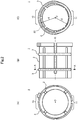
- Figs. 2(A) and 2(B) are respectively a front view and a side view of the rack bush 1
- Fig. 2(C) is an A-A cross-section view of the rack bush 1 shown in Fig. 2(B) .
- the rack bush 1 comprises: a bush body 2 through which the rack bar 5 is inserted; and elastic rings 3 mounted on the bush body 2.
- the present embodiment shows an example in which two elastic rings 3 are mounted on the bush body 2, it is possible that one, three, or more elastic rings 3 are mounted on the bush body 2.
- Figs. 3(A), 3(B), and 3(C) are respectively a front view, a side view, and a back view of the bush body 2
- Fig. 3(D) is a B-B cross-section view of the bush body 2 shown in Fig. 3(A)
- Fig. 3(E) is a C-C cross-section view of the bush body 2 shown in Fig. 3(B) .
- the bush body 2 is formed of synthetic resin having good sliding characteristics such as polyacetal resin, polyamide resin, or polyethylene resin, and is a cylindrical member which can be freely expanded and contracted in the radial direction.
- the bush body 2 comprises: a sliding surface 21, which is formed in an inner peripheral surface 20 and comes in sliding contact with an outer peripheral surface 50 of the rack bar 5 inserted; a plurality of first slits 25 and second slits 26, which are arranged alternately in the circumferential direction at regular intervals; an engagement protrusion 27, which is formed on an outer peripheral surface 22; and mounting grooves 28, which are formed in the outer peripheral surface 22 in the circumferential direction in order to mount the elastic rings 3.
- the first slits 25 are each formed along the direction of the axis O from one end surface 23 toward the other end surface 24, and the second slits 26 are each formed along the direction of the axis O from the other end surface 24 toward the one end surface 23.
- the bush body 2 can be deformed in the diameter contracting direction owing to the plurality of first slits 25 and second slits 26 arranged alternately in the circumferential direction at regular intervals.
- the engagement protrusion 27 protrudes outward in the radial direction from the outer peripheral surface 22 on the side of the one end surface 23, and is received in an engagement recess (not shown) which is formed to cut off the inner peripheral surface 40 at one end surface 41 of the housing 4.
- the rack bush 1 housed in the housing 4 is restricted in rotation around the axis O.
- a ring-shaped lid 6 is attached to the one end surface 41 of the housing 4 in a state that the engagement protrusion 27 is received in the engagement recess of the housing 4.
- the rack bush 1 housed in the housing 4 is restricted in movement in the direction of the axis O (See Fig. 1 ).
- Each of the mounting grooves 28 is formed in the outer peripheral surface 22 along the circumferential direction, and has a large-diameter part 280 where the groove bottom 29 in the circumferential direction has a first radius r1 and a small-diameter part 281 where the groove bottom 29 in the circumferential direction has a second radius r2 smaller than the first radius r1.
- the radius of the outer peripheral surface 22 as r0 and the wire diameter of the elastic body forming the elastic ring 3 as d (See Fig. 4 )
- the first radius r1 is set so that r1 + d > r0.
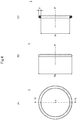
- Figs. 4(A) and 4(B) are respectively a front view and a side view of each elastic ring 3, and Fig. 4(C) is a D-D cross-section view of the elastic ring 3 shown in Fig. 4(A) .
- Each elastic ring 3 is an annular member formed of an elastic body such as synthetic resin, thermoplastic elastomer, or the like, and the inner circumference ⁇ Ri on the side of the inner diameter Ri is shorter than the circumference of the groove bottom 29 of the mounting groove 28 of the bush body 2. Further, the outer diameter Re is larger than the inner diameter Rj of the housing 4 (See Fig. 1 ).
- the circumference ⁇ Ri of the elastic ring 3 on the side of the inner diameter Ri is shorter than the circumference of the groove bottom 29 of the mounting groove 28 of the bush body 2.
- the elastic ring 3 biases the bush body 2 in the direction of contracting the diameter of the bush body 2 and tightens the rack bar 5 inserted in the bush body 2.
- the outer diameter Re of the elastic ring 3 is larger than the inner diameter Rj of the housing 4. Therefore, when the rack bush 1 is housed in the housing 4, the elastic ring 3 comes in pressed contact with the inner peripheral surface 40 of the housing 4, and accordingly is compressively deformed. As a result, the rack bush 1 is fitted in the housing 4.
- a reaction force supporting surface 42 is the inner peripheral surface 40 of the housing 4 opposed to the input direction of the reaction force N inputted to the rack bar 5 from a tire (not shown) via a tie rod (not shown) linked to the rack bar 5, and is an area including the site that generates the greatest reaction force to the reaction force N inputted to the rack bar 5 in the inner peripheral surface 40 of the housing 4.
- the rack bush 1 of the above configuration is positioned by the engagement between the engagement protrusion 27 of the bush body 2 and the engagement recess (not shown) of the housing 4 so that the small-diameter parts 281 of the mounting grooves 28 of the bush body 2 are positioned on the side of the reaction force supporting surface 42, or in other words, the elastic ring embedded parts 11 are positioned on the side of the reaction force supporting surface 42.
- each of the mounting grooves 28 of the bush body 2 has the large-diameter part 280 where the groove bottom in the circumferential direction has the first radius r1 and the small-diameter part 281 where the groove bottom in the circumferential direction has the second radius r2 smaller than the first radius r1.
- the rack bush 1 has the elastic protruding parts 10, in each of which the elastic ring 3 protrudes largely from the outer peripheral surface 22 of the bush body 2, and the elastic ring embedded parts 11, in each of which the elastic ring 3 is embedded in the outer peripheral surface 22 of the bush body 2.
- the rack bush 1 is housed in the housing 4, being positioned so that the elastic ring embedded parts 11 are positioned on the side of the reaction force supporting surface 42.
- the outer peripheral surface 22 of the bush body 2 is abutted against the inner peripheral surface 40 of the housing 4 without intervention of the elastic rings 3, and there is no gap between the outer peripheral surface 22 of the bush body 2 and the inner peripheral surface 40 of the housing 4.
- This improves the rigidity on the side of the reaction force supporting surface 42 and can suppress movement of the rack bar 5 within the housing 4 owing to the reaction force N of a tire. Thereby, the time lag from steering operation to actual change of the tire direction is reduced.
- the present embodiment can provide the rack bush 1 that reduces the effect on the feeling of steering operation.
- the present invention is not limited to the above embodiment, and can be varied variously.
- the present invention is not limited to this.
- the second radius r2 of the groove bottom 29 in the circumferential direction at the small-diameter part 281 of the mounting groove 28 is set so that the elastic ring 3 is embedded in the outer peripheral surface 22 of the bush body 2 at the elastic ring embedded part 11 or the amount of protrusion of the elastic ring 3 from the outer peripheral surface 22 of the bush body 2 is smaller than that at the elastic ring protruding part 10.
- the gap between the outer peripheral surface 22 of the bush body 2 and the inner peripheral surface 40 of the housing 4 is made smaller on the side of the reaction force supporting surface 42 of the housing 4, and movement of the rack bar 5 inside the housing 4 owing to the tire's reaction force N is suppressed. Accordingly, the time lag from steering operation to actual change of the tire direction is reduced.
- the first slits 25 and the second slits 26 can be omitted from the bush body 2 on the side of the elastic ring protruding parts 10 (the large-diameter parts 280 of the mounting grooves 28).
- the first slits 25 and the second slits 26 can be arranged only on the side of the elastic ring embedded parts 11 (the small-diameter parts 281 of the mounting grooves 28).
- a plurality of first slits 25 are formed in the bush body 2 along the direction of the axis O from the one end surface 23 toward the other end surface 24, and a plurality of second slits 26 are formed along the direction of the axis O from the other end surface 24 toward the one end surface 23.
- the present invention is not limited to this. It is good enough if the bush body 2 can be freely expanded and contracted in radial direction.
- the bush body 2 may have only the first slits 25 or only the second slits 26.
- the bush body 2 has the cylindrical shape. However, it is good enough if the bush body 2 has a tubular shape adapted to the shape of the rack bar 5 to be inserted.
- 1, 1A rack bush; 2: bush body; 3: elastic ring; 4: housing; 5: rack bar; 6: lid; 10: elastic ring protruding part; 11: elastic ring embedded part; 20: inner peripheral surface of the bush body 2; 21: sliding surface of the bush body 2; 22: outer peripheral surface of the bush body 2; 23, 24: end surface of the bush body 2; 25: first slit; 26: second slit; 27: engagement part; 28: mounting groove; 29: groove bottom of the mounting groove 28; 40: inner peripheral surface of the housing 4; 41: end surface of the housing 4; 42: reaction force supporting surface of the housing 4; 43: reaction force supporting surface opposed surface of the housing 4; 280: large-diameter part of the mounting groove 28; and 281: small-diameter part of the mounting groove.
Landscapes
- Engineering & Computer Science (AREA)
- General Engineering & Computer Science (AREA)
- Mechanical Engineering (AREA)
- Chemical & Material Sciences (AREA)
- Combustion & Propulsion (AREA)
- Transportation (AREA)
- Support Of The Bearing (AREA)
- Sliding-Contact Bearings (AREA)
- Bearings For Parts Moving Linearly (AREA)
Abstract
Description
- The present invention relates to a bearing, and in particular to a bearing suitable for a rack bush used in a rack-and-pinion steering mechanism.
- The
Patent Literature 1 describes a rack bush used in a rack-and-pinion steering mechanism. This rack bush is housed in a circular cylindrical housing in a state that movement in the axial direction is restricted, and supports the load applied to a rack bar while allowing movement of the rack bar in the axial direction. The rack bush comprises: a circular cylindrical bearing body, which can be freely expanded and contracted in the radial direction, and into which the rack bar is inserted; and elastic rings, which are mounted on the bearing body and bias the bearing body inward in the radial direction. The bearing body is made of synthetic resin, and mounting grooves for mounting the elastic rings are formed in the outer peripheral surface of the bearing body, each in the circumferential direction. - According to this rack bush, the bearing body is contracted in diameter by the elastic rings so that the rack bar inserted in the bearing body is tightened. As a result, the clearance between the inner peripheral surface of the bearing body and the outer peripheral surface of the rack bar is made to be zero, and thus it is possible to prevent generation of unpleasant sound owing to collision between the inner peripheral surface of the bearing body and the outer peripheral surface of the rack bar. Further, it is possible to prevent variation in the friction torque caused by a dimension error of the outer diameter of the rack bar.
- Patent Literature 1: Japanese Unexamined Patent Application Laid-Open No.
2008-151289 - When a steering shaft is rotated by steering operation in a rack-and-pinion steering mechanism, the rotational movement of the steering shaft is converted into the linear movement of the rack bar owing to engagement between a pinion gear formed in the end portion of the steering shaft and a rack gear formed in the rack bar. As a result, tie rods interlocked with the rack bar give torque for rotating tires around their kingpins to steering knuckles via the tie rod ends. At that time, reaction force from the tires is inputted into the rack bar via the steering knuckles, the tie rod ends, and the tie rods.
- Here, since the rack bush described in the
Patent Literature 1 is housed in the housing with the elastic rings mounted on the bearing body being abutted against the inner peripheral surface of the housing, the elastic rings are compressively deformed and moved within the housing owing to the reaction force from the tires inputted into the rack bar. Accordingly, the time lag from the steering operation to actual change of the directions of the tires becomes larger, and this affects feeling of steering operation unfavorably. - The present invention has been made taking the above conditions into consideration, and an object of the invention is to provide a bearing suitable for a rack bush that can reduce a bad effect on the feeling of steering operation.
- To solve the above problems, according to the present invention, a mounting groove for mounting an elastic ring is formed in the circumferential direction in the outer peripheral surface of a bush body through which a rack bar is inserted, so as to be provided with a large-diameter part where the groove bottom in the circumferential direction has a first radius and a small-diameter part where the groove bottom in the circumferential direction has a second radius smaller than the first radius. Here, it is favorable that a sum of the first radius and the wire diameter of the elastic body forming the elastic ring is larger than the radius of the outer peripheral surface of the bush body while a sum of the second radius and the wire diameter of the elastic body forming the elastic ring is smaller than or equal to the radius of the outer peripheral surface of the bush body.
- For example, the present invention provides a bearing, comprising:
- a bush body which can be freely expanded and contracted in a radial direction; and
- an elastic ring mounted on the bush body;
- the bush body has a mounting groove formed in an outer peripheral surface in a circumferential direction for mounting the elastic ring; and
- the mounting groove has:
- a large-diameter part where a groove bottom in a circumferential direction of the mounting groove has a first radius; and
- a small-diameter part where the groove bottom in the circumferential direction has a second radius smaller than the first radius.
- Further, the present invention provides a rack-and-pinion steering mechanism, comprising:
- the above-mentioned bearing, which supports a load applied to a rack bar while allowing movement of the rack bar in an axial direction; and
- a cylindrical housing, which houses the bearing while restricting movement of the bearing in the axial direction;
- wherein, the bearing is housed in the housing so that the small-diameter part of the mounting groove faces a reaction force supporting surface which is an inner peripheral surface of the housing opposed to an input direction of a reaction force inputted to the rack bar from a tire via a tie rod linked to the rack bar.
- According to the present invention, the mounting groove for mounting the elastic ring has the large-diameter part where the groove bottom in the circumferential direction has a first radius and a small diameter part where the groove bottom in the circumferential direction has a second radius smaller than the first radius. As a result, there are formed an elastic ring protruding part where the elastic ring protrudes largely from the outer peripheral surface of the bush body and an elastic ring embedded part where the elastic ring is embedded in or protrudes small from the outer peripheral part of the bush body. By mounting the rack bush in the housing so that the elastic ring embedded part is opposed to the reaction force supporting surface, which is the inner peripheral surface of the housing in opposition to the input direction of reaction force inputted to the rack bar from a tire via a tie rod, it is possible to reduce the gap between the outer peripheral surface of the bush body and the reaction force supporting surface. Accordingly, the rigidity against reaction force of tire is improved, and movement of the rack bar within the housing owing to the reaction force of tire can be restricted, and therefore the time lag from steering operation to actual change of the tire direction is reduced. Further, in the present invention, since it is not necessary to shorten the circumference of the elastic ring on the inner peripheral side to strengthen tightening of the rack bar for improvement of the rigidity against reaction force of tire, the sliding characteristics of the rack bush are not affected. Thus, the present invention can provide a rack bush that can reduce the effect on the feeling of steering operation.
-
-
Fig. 1 is a partial cross-section view of a part of a rack-and-pinion steering mechanism according to one embodiment of the present invention; -
Figs. 2(A) and 2(B) are respectively a front view and a side view of arack bush 1, andFig. 2(C) is an A-A cross-section view of therack bush 1 shown inFig. 2(B) ; -
Figs. 3(A), 3(B), and 3(C) are respectively a front view, a side view, and a back view of abush body 2,Fig. 3(D) is a B-B cross-section view of thebush body 2 shown inFig. 3(A), and Fig. 3(E) is a C-C cross-section view of thebush body 2 shown inFig. 3(B) ; -
Figs. 4(A) and 4(B) are respectively a front view and a side view of anelastic ring 3, andFig. 4(C) is a D-D cross-section view of theelastic ring 3 shown inFig. 4(A) ; and -
Figs. 5(A) and 5(B) are respectively a front view and a side view of avariant 1A of therack bush 1, andFig. 5(C) is an E-E cross-section view of thevariant 1A of therack bush 1 shown inFig. 5(B) . - In the following, one embodiment of the present invention will be described referring to the drawings.
-
Fig. 1 is a partial cross-section view of a part of a rack-and-pinion steering mechanism according to the present embodiment. - As shown in the figure, the rack-and-pinion steering mechanism of the present embodiment comprises: a
rack bush 1, which supports a load applied to arack bar 5 while allowing movement of therack bar 5 in the direction of the axis O; and a cylindrical housing 4, which houses therack bush 1 while restricting movement of therack bush 1 in the direction of the axis O. -
Figs. 2(A) and 2(B) are respectively a front view and a side view of therack bush 1, andFig. 2(C) is an A-A cross-section view of therack bush 1 shown inFig. 2(B) . - As shown in the figures, the
rack bush 1 comprises: abush body 2 through which therack bar 5 is inserted; andelastic rings 3 mounted on thebush body 2. Although the present embodiment shows an example in which twoelastic rings 3 are mounted on thebush body 2, it is possible that one, three, or moreelastic rings 3 are mounted on thebush body 2. -
Figs. 3(A), 3(B), and 3(C) are respectively a front view, a side view, and a back view of thebush body 2,Fig. 3(D) is a B-B cross-section view of thebush body 2 shown inFig. 3(A), and Fig. 3(E) is a C-C cross-section view of thebush body 2 shown inFig. 3(B) . - The
bush body 2 is formed of synthetic resin having good sliding characteristics such as polyacetal resin, polyamide resin, or polyethylene resin, and is a cylindrical member which can be freely expanded and contracted in the radial direction. As shown in the figure, thebush body 2 comprises: asliding surface 21, which is formed in an innerperipheral surface 20 and comes in sliding contact with an outerperipheral surface 50 of therack bar 5 inserted; a plurality offirst slits 25 andsecond slits 26, which are arranged alternately in the circumferential direction at regular intervals; anengagement protrusion 27, which is formed on an outerperipheral surface 22; and mountinggrooves 28, which are formed in the outerperipheral surface 22 in the circumferential direction in order to mount theelastic rings 3. - The
first slits 25 are each formed along the direction of the axis O from oneend surface 23 toward theother end surface 24, and thesecond slits 26 are each formed along the direction of the axis O from theother end surface 24 toward the oneend surface 23. Thebush body 2 can be deformed in the diameter contracting direction owing to the plurality offirst slits 25 andsecond slits 26 arranged alternately in the circumferential direction at regular intervals. - The
engagement protrusion 27 protrudes outward in the radial direction from the outerperipheral surface 22 on the side of the oneend surface 23, and is received in an engagement recess (not shown) which is formed to cut off the innerperipheral surface 40 at oneend surface 41 of the housing 4. By this arrangement, therack bush 1 housed in the housing 4 is restricted in rotation around the axis O. Further, a ring-shaped lid 6 is attached to the oneend surface 41 of the housing 4 in a state that theengagement protrusion 27 is received in the engagement recess of the housing 4. As a result, therack bush 1 housed in the housing 4 is restricted in movement in the direction of the axis O (SeeFig. 1 ). - Each of the
mounting grooves 28 is formed in the outerperipheral surface 22 along the circumferential direction, and has a large-diameter part 280 where thegroove bottom 29 in the circumferential direction has a first radius r1 and a small-diameter part 281 where thegroove bottom 29 in the circumferential direction has a second radius r2 smaller than the first radius r1. Here, expressing the radius of the outerperipheral surface 22 as r0 and the wire diameter of the elastic body forming theelastic ring 3 as d (SeeFig. 4 ), the first radius r1 is set so that r1 + d > r0. On the other hand, the second radius r2 is set so that r2 + d <= r0. As a result, in therack bush 1, there are formed an elasticring protruding part 10, where theelastic ring 3 protrudes largely from the outerperipheral surface 22 of thebush body 2, and an elastic ring embeddedpart 11, where theelastic ring 3 is embedded in the outerperipheral surface 22 of the bush body 2 (SeeFig. 2 ). -
Figs. 4(A) and 4(B) are respectively a front view and a side view of eachelastic ring 3, andFig. 4(C) is a D-D cross-section view of theelastic ring 3 shown inFig. 4(A) . - Each
elastic ring 3 is an annular member formed of an elastic body such as synthetic resin, thermoplastic elastomer, or the like, and the inner circumference πRi on the side of the inner diameter Ri is shorter than the circumference of thegroove bottom 29 of the mountinggroove 28 of thebush body 2. Further, the outer diameter Re is larger than the inner diameter Rj of the housing 4 (SeeFig. 1 ). - The circumference πRi of the
elastic ring 3 on the side of the inner diameter Ri is shorter than the circumference of thegroove bottom 29 of the mountinggroove 28 of thebush body 2. Thus, when theelastic ring 3 is mounted in the mountinggroove 28 of thebush body 2, theelastic ring 3 biases thebush body 2 in the direction of contracting the diameter of thebush body 2 and tightens therack bar 5 inserted in thebush body 2. Further, the outer diameter Re of theelastic ring 3 is larger than the inner diameter Rj of the housing 4. Therefore, when therack bush 1 is housed in the housing 4, theelastic ring 3 comes in pressed contact with the innerperipheral surface 40 of the housing 4, and accordingly is compressively deformed. As a result, therack bush 1 is fitted in the housing 4. - In
Fig. 1 , a reactionforce supporting surface 42 is the innerperipheral surface 40 of the housing 4 opposed to the input direction of the reaction force N inputted to therack bar 5 from a tire (not shown) via a tie rod (not shown) linked to therack bar 5, and is an area including the site that generates the greatest reaction force to the reaction force N inputted to therack bar 5 in the innerperipheral surface 40 of the housing 4. Therack bush 1 of the above configuration is positioned by the engagement between theengagement protrusion 27 of thebush body 2 and the engagement recess (not shown) of the housing 4 so that the small-diameter parts 281 of the mountinggrooves 28 of thebush body 2 are positioned on the side of the reactionforce supporting surface 42, or in other words, the elastic ring embeddedparts 11 are positioned on the side of the reactionforce supporting surface 42. - Herein above, one embodiment of the present invention has been described.
- In the present embodiment, each of the mounting
grooves 28 of thebush body 2 has the large-diameter part 280 where the groove bottom in the circumferential direction has the first radius r1 and the small-diameter part 281 where the groove bottom in the circumferential direction has the second radius r2 smaller than the first radius r1. Accordingly, therack bush 1 has the elastic protrudingparts 10, in each of which theelastic ring 3 protrudes largely from the outerperipheral surface 22 of thebush body 2, and the elastic ring embeddedparts 11, in each of which theelastic ring 3 is embedded in the outerperipheral surface 22 of thebush body 2. Therack bush 1 is housed in the housing 4, being positioned so that the elastic ring embeddedparts 11 are positioned on the side of the reactionforce supporting surface 42. - Accordingly, on the side of the reaction
force supporting surface 42 of the housing 4, the outerperipheral surface 22 of thebush body 2 is abutted against the innerperipheral surface 40 of the housing 4 without intervention of theelastic rings 3, and there is no gap between the outerperipheral surface 22 of thebush body 2 and the innerperipheral surface 40 of the housing 4. This improves the rigidity on the side of the reactionforce supporting surface 42 and can suppress movement of therack bar 5 within the housing 4 owing to the reaction force N of a tire. Thereby, the time lag from steering operation to actual change of the tire direction is reduced. - Further, it is not necessary to shorten the circumference of each
elastic ring 3 on the side of the inner diameter Ri to tighten more firmly therack bar 5 in order to improve the rigidity on the reactionforce supporting surface 42. Accordingly, the sliding characteristics of therack bush 1 are not affected. - Thus, the present embodiment can provide the
rack bush 1 that reduces the effect on the feeling of steering operation. - Further, in comparison with the conventional rack bush whose mounting grooves have groove bottoms of a constant radius with respect to the circumferential direction (that is to say, groove bottoms each of a perfect circle), it is possible to increase the compressive deformation amount of the elastic body forming each
elastic ring 3 on the side of the reaction force supporting surface opposedsurface 43 which is the innerperipheral surface 40 of the housing 4 opposed to the reactionforce supporting surface 42 across the axis O, and the spring force as the reaction force is applied toward the inner peripheral surface of therack bush 1. Accordingly, the rigidity is improved not only on the side of the reactionforce supporting surface 42 but also on the side of the reaction force supporting surface opposedsurface 43, and the effect on the feeling of steering operation can be further reduced. - The present invention is not limited to the above embodiment, and can be varied variously.
- For example, in the above embodiment, expressing the radius of the outer
peripheral surface 22 of thebush body 2 as r0 and the wire diameter of the elastic body forming eachelastic ring 3 as d, the second radius r2 of the groove bottom 29 in the circumferential direction at the small-diameter part 281 of the mounting groove 8 is set so that r2 + d <= r0. The present invention, however, is not limited to this. - It is sufficient that the second radius r2 of the groove bottom 29 in the circumferential direction at the small-
diameter part 281 of the mountinggroove 28 is set so that theelastic ring 3 is embedded in the outerperipheral surface 22 of thebush body 2 at the elastic ring embeddedpart 11 or the amount of protrusion of theelastic ring 3 from the outerperipheral surface 22 of thebush body 2 is smaller than that at the elasticring protruding part 10. By this arrangement, the gap between the outerperipheral surface 22 of thebush body 2 and the innerperipheral surface 40 of the housing 4 is made smaller on the side of the reactionforce supporting surface 42 of the housing 4, and movement of therack bar 5 inside the housing 4 owing to the tire's reaction force N is suppressed. Accordingly, the time lag from steering operation to actual change of the tire direction is reduced. - Further, in the above embodiment, as shown in a
variant 1A of therack bush 1 shown inFigs. 5(A) - 5(C) , thefirst slits 25 and thesecond slits 26 can be omitted from thebush body 2 on the side of the elastic ring protruding parts 10 (the large-diameter parts 280 of the mounting grooves 28). In other words, thefirst slits 25 and thesecond slits 26 can be arranged only on the side of the elastic ring embedded parts 11 (the small-diameter parts 281 of the mounting grooves 28). By this arrangement, it is possible to avoid escape of the elastically-deformedelastic rings 3 into thefirst slits 25 and the second slits 26 on the side of the reaction force supporting surface opposedsurface 43 and to increase furthermore the compressive deformation amount of the elastic body forming eachelastic ring 3. Thereby, the reaction force of theelastic rings 3 on the side of the reaction force supporting surface opposedsurface 43 becomes larger, and the rigidity on the side of the reaction force supporting surface opposedsurface 43 is improved furthermore. - Further, in the above embodiment, a plurality of
first slits 25 are formed in thebush body 2 along the direction of the axis O from the oneend surface 23 toward theother end surface 24, and a plurality ofsecond slits 26 are formed along the direction of the axis O from theother end surface 24 toward the oneend surface 23. The present invention, however, is not limited to this. It is good enough if thebush body 2 can be freely expanded and contracted in radial direction. For example, thebush body 2 may have only thefirst slits 25 or only thesecond slits 26. Further, in the above embodiment, thebush body 2 has the cylindrical shape. However, it is good enough if thebush body 2 has a tubular shape adapted to the shape of therack bar 5 to be inserted. - Further, the above embodiment has been described taking an example of rack bush used in a rack-and-pinion steering mechanism. The present invention is not limited to this, and can be widely applied to a bearing for supporting a load of an inserted axial member.
- 1, 1A: rack bush; 2: bush body; 3: elastic ring; 4: housing; 5: rack bar; 6: lid; 10: elastic ring protruding part; 11: elastic ring embedded part; 20: inner peripheral surface of the
bush body 2; 21: sliding surface of thebush body 2; 22: outer peripheral surface of thebush body 2; 23, 24: end surface of thebush body 2; 25: first slit; 26: second slit; 27: engagement part; 28: mounting groove; 29: groove bottom of the mountinggroove 28; 40: inner peripheral surface of the housing 4; 41: end surface of the housing 4; 42: reaction force supporting surface of the housing 4; 43: reaction force supporting surface opposed surface of the housing 4; 280: large-diameter part of the mountinggroove 28; and 281: small-diameter part of the mounting groove.
Claims (6)
- A bearing, comprising:a bush body which can be freely expanded and contracted in radial direction; andan elastic ring mounted on the bush body;wherein:the bush body has a mounting groove formed in an outer peripheral surface in a circumferential direction for mounting the elastic ring; andthe mounting groove has:a large-diameter part where a radius of a groove bottom of the mounting groove is a first radius; anda small-diameter part where a radius of the groove bottom is a second radius smaller than the first radius.
- A bearing of Claim 1, wherein:
an amount of protrusion of the elastic ring from the large-diameter part is larger than an amount of protrusion from the small-diameter part. - A bearing of Claim 1, wherein:a sum of the first radius and a wire diameter of an elastic body forming the elastic ring is larger than a radius of the outer peripheral surface of the bush body; anda sum of the second radius and the wire diameter of the elastic body forming the elastic ring is smaller than or equal to the radius of the outer peripheral surface of the bush body.
- A bearing of one of Claims 1 - 3, wherein:
the bush body has slits, each of which is formed from one end surface toward the other end surface. - A bearing of Claim 4, wherein:
the slits are arranged in a circumferential direction of the bush body on the side of the small-diameter part of the mounting groove. - A rack-and-pinion steering mechanism, comprising:a bearing of one of Claims 1 - 5, which supports a load applied to a rack bar while allowing movement of the rack bar in an axial direction; anda cylindrical housing, which houses the bearing while restricting movement of the bearing in the axial direction;wherein, the bearing is housed in the housing so that the small-diameter part of the mounting groove faces a reaction force supporting surface which is an inner peripheral surface of the housing opposed to an input direction of a reaction force inputted to the rack bar from a tire via a tie rod linked to the rack bar.
Applications Claiming Priority (2)
| Application Number | Priority Date | Filing Date | Title |
|---|---|---|---|
| JP2017151134A JP6783719B2 (en) | 2017-08-03 | 2017-08-03 | Bearing and steering mechanism |
| PCT/JP2018/028735 WO2019026928A1 (en) | 2017-08-03 | 2018-07-31 | Bearing and steering mechanism |
Publications (3)
| Publication Number | Publication Date |
|---|---|
| EP3663598A1 true EP3663598A1 (en) | 2020-06-10 |
| EP3663598A4 EP3663598A4 (en) | 2021-05-05 |
| EP3663598B1 EP3663598B1 (en) | 2021-11-17 |
Family
ID=65232795
Family Applications (1)
| Application Number | Title | Priority Date | Filing Date |
|---|---|---|---|
| EP18840701.9A Active EP3663598B1 (en) | 2017-08-03 | 2018-07-31 | Bearing and steering mechanism |
Country Status (5)
| Country | Link |
|---|---|
| US (1) | US11548546B2 (en) |
| EP (1) | EP3663598B1 (en) |
| JP (1) | JP6783719B2 (en) |
| CN (1) | CN110998110B (en) |
| WO (1) | WO2019026928A1 (en) |
Families Citing this family (7)
| Publication number | Priority date | Publication date | Assignee | Title |
|---|---|---|---|---|
| JP6934801B2 (en) * | 2017-10-20 | 2021-09-15 | マツダ株式会社 | Rack bush and steering mechanism |
| US10837677B2 (en) * | 2018-09-05 | 2020-11-17 | Ojjo, Inc. | Multi-piece truss legs and related couplers |
| JP7324607B2 (en) * | 2019-04-15 | 2023-08-10 | マツダ株式会社 | steering device |
| JP7344027B2 (en) * | 2019-07-12 | 2023-09-13 | Kyb株式会社 | steering device |
| US11313508B2 (en) * | 2019-09-04 | 2022-04-26 | Raytheon Company | Radial positioning device |
| US11293488B1 (en) | 2021-07-02 | 2022-04-05 | Alfredo A. Ciotola | Compressively resilient bushing |
| CN114537508A (en) * | 2022-02-28 | 2022-05-27 | 重庆长安汽车股份有限公司 | Mechanical steering gear assembly of automobile |
Family Cites Families (21)
| Publication number | Priority date | Publication date | Assignee | Title |
|---|---|---|---|---|
| JP2005178482A (en) | 2003-12-17 | 2005-07-07 | Koyo Seiko Co Ltd | Steering device |
| JP4935080B2 (en) * | 2006-01-16 | 2012-05-23 | 株式会社ジェイテクト | Bush bearing and automotive rack-pinion steering apparatus using the same |
| US7665747B2 (en) * | 2006-10-13 | 2010-02-23 | Gm Global Technology Operations, Inc. | Steering gear assembly having rack bushing |
| JP4940931B2 (en) | 2006-12-19 | 2012-05-30 | オイレス工業株式会社 | Plain bearing |
| JP5167754B2 (en) * | 2007-10-18 | 2013-03-21 | オイレス工業株式会社 | Bush bearing |
| JP5481777B2 (en) * | 2007-10-23 | 2014-04-23 | 株式会社ジェイテクト | Bearing mechanism with sliding bearing |
| JP5141339B2 (en) * | 2008-03-31 | 2013-02-13 | オイレス工業株式会社 | Bush bearing and automotive rack-pinion steering apparatus using the same |
| JP5461350B2 (en) * | 2010-09-08 | 2014-04-02 | 株式会社ショーワ | Plain bearing |
| JP2014047833A (en) * | 2012-08-30 | 2014-03-17 | Oiles Ind Co Ltd | Bush bearing and rack-and-pinion type steering gear of automobile using bush bearing |
| US9663137B2 (en) | 2013-06-05 | 2017-05-30 | Nsk Ltd. | Guide bush and rack-and-pinion steering gear unit |
| JP2015013562A (en) | 2013-07-04 | 2015-01-22 | 株式会社ジェイテクト | Steering device |
| JP6150119B2 (en) | 2013-07-22 | 2017-06-21 | 株式会社ジェイテクト | Rack bush |
| JP6034812B2 (en) * | 2014-01-23 | 2016-11-30 | 株式会社ショーワ | Bush bearing structure |
| JP6434327B2 (en) * | 2015-02-03 | 2018-12-05 | オイレス工業株式会社 | Plain bearing |
| JP6572624B2 (en) * | 2015-05-20 | 2019-09-11 | オイレス工業株式会社 | Sliding bearing and bearing mechanism including the same |
| JP2017019414A (en) * | 2015-07-10 | 2017-01-26 | 株式会社ジェイテクト | Rack Bush |
| JP2017087972A (en) * | 2015-11-10 | 2017-05-25 | 株式会社ジェイテクト | Steering shaft support structure |
| JP2019027559A (en) * | 2017-08-02 | 2019-02-21 | オイレス工業株式会社 | Bearing and steering mechanism |
| JP6934801B2 (en) * | 2017-10-20 | 2021-09-15 | マツダ株式会社 | Rack bush and steering mechanism |
| CN109131535A (en) * | 2018-08-15 | 2019-01-04 | 重庆长安汽车股份有限公司 | A kind of steering gear rack bushing and the steering assembly comprising the bushing |
| JP7324607B2 (en) * | 2019-04-15 | 2023-08-10 | マツダ株式会社 | steering device |
-
2017
- 2017-08-03 JP JP2017151134A patent/JP6783719B2/en active Active
-
2018
- 2018-07-31 EP EP18840701.9A patent/EP3663598B1/en active Active
- 2018-07-31 CN CN201880048476.9A patent/CN110998110B/en active Active
- 2018-07-31 US US16/635,184 patent/US11548546B2/en active Active
- 2018-07-31 WO PCT/JP2018/028735 patent/WO2019026928A1/en unknown
Also Published As
| Publication number | Publication date |
|---|---|
| US11548546B2 (en) | 2023-01-10 |
| JP6783719B2 (en) | 2020-11-11 |
| EP3663598A4 (en) | 2021-05-05 |
| US20200346681A1 (en) | 2020-11-05 |
| EP3663598B1 (en) | 2021-11-17 |
| WO2019026928A1 (en) | 2019-02-07 |
| CN110998110B (en) | 2021-12-17 |
| CN110998110A (en) | 2020-04-10 |
| JP2019027575A (en) | 2019-02-21 |
Similar Documents
| Publication | Publication Date | Title |
|---|---|---|
| EP3663598B1 (en) | Bearing and steering mechanism | |
| US11254347B2 (en) | Rack bush and steering mechanism | |
| US10259488B2 (en) | Steering system | |
| EP2202129B1 (en) | Bearing mechanism with slide bearing | |
| EP1394426B1 (en) | Sliding bearing and bearing mechanism having the same | |
| US7926378B2 (en) | Rack and pinion type power steering apparatus | |
| EP3168115A1 (en) | Steered shaft support structure | |
| JP7156379B2 (en) | Rack and pinion type steering gear unit | |
| EP3299647B1 (en) | Slide bearing and bearing mechanism provided with same | |
| JP2019027559A (en) | Bearing and steering mechanism | |
| US11873031B2 (en) | Rack and pinion steering gear unit | |
| JP2017007428A (en) | Rack and pinion type steering device | |
| JPH0425610A (en) | Spherical sliding bush | |
| US10520073B2 (en) | Gear wheel | |
| JP2019019952A (en) | Slide bearing |
Legal Events
| Date | Code | Title | Description |
|---|---|---|---|
| STAA | Information on the status of an ep patent application or granted ep patent |
Free format text: STATUS: THE INTERNATIONAL PUBLICATION HAS BEEN MADE |
|
| PUAI | Public reference made under article 153(3) epc to a published international application that has entered the european phase |
Free format text: ORIGINAL CODE: 0009012 |
|
| STAA | Information on the status of an ep patent application or granted ep patent |
Free format text: STATUS: REQUEST FOR EXAMINATION WAS MADE |
|
| 17P | Request for examination filed |
Effective date: 20200122 |
|
| AK | Designated contracting states |
Kind code of ref document: A1 Designated state(s): AL AT BE BG CH CY CZ DE DK EE ES FI FR GB GR HR HU IE IS IT LI LT LU LV MC MK MT NL NO PL PT RO RS SE SI SK SM TR |
|
| AX | Request for extension of the european patent |
Extension state: BA ME |
|
| DAV | Request for validation of the european patent (deleted) | ||
| DAX | Request for extension of the european patent (deleted) | ||
| A4 | Supplementary search report drawn up and despatched |
Effective date: 20210406 |
|
| RIC1 | Information provided on ipc code assigned before grant |
Ipc: F16C 25/04 20060101AFI20210329BHEP Ipc: B62D 3/12 20060101ALI20210329BHEP Ipc: F16C 17/02 20060101ALI20210329BHEP Ipc: F16C 29/02 20060101ALI20210329BHEP Ipc: F16C 29/00 20060101ALI20210329BHEP |
|
| GRAP | Despatch of communication of intention to grant a patent |
Free format text: ORIGINAL CODE: EPIDOSNIGR1 |
|
| STAA | Information on the status of an ep patent application or granted ep patent |
Free format text: STATUS: GRANT OF PATENT IS INTENDED |
|
| RIC1 | Information provided on ipc code assigned before grant |
Ipc: F16C 25/04 20060101AFI20210614BHEP Ipc: B62D 3/12 20060101ALI20210614BHEP Ipc: F16C 17/02 20060101ALI20210614BHEP Ipc: F16C 29/02 20060101ALI20210614BHEP Ipc: F16C 29/00 20060101ALI20210614BHEP |
|
| INTG | Intention to grant announced |
Effective date: 20210705 |
|
| GRAS | Grant fee paid |
Free format text: ORIGINAL CODE: EPIDOSNIGR3 |
|
| GRAA | (expected) grant |
Free format text: ORIGINAL CODE: 0009210 |
|
| STAA | Information on the status of an ep patent application or granted ep patent |
Free format text: STATUS: THE PATENT HAS BEEN GRANTED |
|
| AK | Designated contracting states |
Kind code of ref document: B1 Designated state(s): AL AT BE BG CH CY CZ DE DK EE ES FI FR GB GR HR HU IE IS IT LI LT LU LV MC MK MT NL NO PL PT RO RS SE SI SK SM TR |
|
| REG | Reference to a national code |
Ref country code: GB Ref legal event code: FG4D |
|
| REG | Reference to a national code |
Ref country code: DE Ref legal event code: R096 Ref document number: 602018026966 Country of ref document: DE |
|
| REG | Reference to a national code |
Ref country code: IE Ref legal event code: FG4D |
|
| REG | Reference to a national code |
Ref country code: AT Ref legal event code: REF Ref document number: 1448291 Country of ref document: AT Kind code of ref document: T Effective date: 20211215 |
|
| REG | Reference to a national code |
Ref country code: LT Ref legal event code: MG9D |
|
| REG | Reference to a national code |
Ref country code: NL Ref legal event code: MP Effective date: 20211117 |
|
| REG | Reference to a national code |
Ref country code: AT Ref legal event code: MK05 Ref document number: 1448291 Country of ref document: AT Kind code of ref document: T Effective date: 20211117 |
|
| PG25 | Lapsed in a contracting state [announced via postgrant information from national office to epo] |
Ref country code: RS Free format text: LAPSE BECAUSE OF FAILURE TO SUBMIT A TRANSLATION OF THE DESCRIPTION OR TO PAY THE FEE WITHIN THE PRESCRIBED TIME-LIMIT Effective date: 20211117 Ref country code: LT Free format text: LAPSE BECAUSE OF FAILURE TO SUBMIT A TRANSLATION OF THE DESCRIPTION OR TO PAY THE FEE WITHIN THE PRESCRIBED TIME-LIMIT Effective date: 20211117 Ref country code: FI Free format text: LAPSE BECAUSE OF FAILURE TO SUBMIT A TRANSLATION OF THE DESCRIPTION OR TO PAY THE FEE WITHIN THE PRESCRIBED TIME-LIMIT Effective date: 20211117 Ref country code: BG Free format text: LAPSE BECAUSE OF FAILURE TO SUBMIT A TRANSLATION OF THE DESCRIPTION OR TO PAY THE FEE WITHIN THE PRESCRIBED TIME-LIMIT Effective date: 20220217 Ref country code: AT Free format text: LAPSE BECAUSE OF FAILURE TO SUBMIT A TRANSLATION OF THE DESCRIPTION OR TO PAY THE FEE WITHIN THE PRESCRIBED TIME-LIMIT Effective date: 20211117 |
|
| PG25 | Lapsed in a contracting state [announced via postgrant information from national office to epo] |
Ref country code: IS Free format text: LAPSE BECAUSE OF FAILURE TO SUBMIT A TRANSLATION OF THE DESCRIPTION OR TO PAY THE FEE WITHIN THE PRESCRIBED TIME-LIMIT Effective date: 20220317 Ref country code: SE Free format text: LAPSE BECAUSE OF FAILURE TO SUBMIT A TRANSLATION OF THE DESCRIPTION OR TO PAY THE FEE WITHIN THE PRESCRIBED TIME-LIMIT Effective date: 20211117 Ref country code: PT Free format text: LAPSE BECAUSE OF FAILURE TO SUBMIT A TRANSLATION OF THE DESCRIPTION OR TO PAY THE FEE WITHIN THE PRESCRIBED TIME-LIMIT Effective date: 20220317 Ref country code: PL Free format text: LAPSE BECAUSE OF FAILURE TO SUBMIT A TRANSLATION OF THE DESCRIPTION OR TO PAY THE FEE WITHIN THE PRESCRIBED TIME-LIMIT Effective date: 20211117 Ref country code: NO Free format text: LAPSE BECAUSE OF FAILURE TO SUBMIT A TRANSLATION OF THE DESCRIPTION OR TO PAY THE FEE WITHIN THE PRESCRIBED TIME-LIMIT Effective date: 20220217 Ref country code: NL Free format text: LAPSE BECAUSE OF FAILURE TO SUBMIT A TRANSLATION OF THE DESCRIPTION OR TO PAY THE FEE WITHIN THE PRESCRIBED TIME-LIMIT Effective date: 20211117 Ref country code: LV Free format text: LAPSE BECAUSE OF FAILURE TO SUBMIT A TRANSLATION OF THE DESCRIPTION OR TO PAY THE FEE WITHIN THE PRESCRIBED TIME-LIMIT Effective date: 20211117 Ref country code: HR Free format text: LAPSE BECAUSE OF FAILURE TO SUBMIT A TRANSLATION OF THE DESCRIPTION OR TO PAY THE FEE WITHIN THE PRESCRIBED TIME-LIMIT Effective date: 20211117 Ref country code: GR Free format text: LAPSE BECAUSE OF FAILURE TO SUBMIT A TRANSLATION OF THE DESCRIPTION OR TO PAY THE FEE WITHIN THE PRESCRIBED TIME-LIMIT Effective date: 20220218 Ref country code: ES Free format text: LAPSE BECAUSE OF FAILURE TO SUBMIT A TRANSLATION OF THE DESCRIPTION OR TO PAY THE FEE WITHIN THE PRESCRIBED TIME-LIMIT Effective date: 20211117 |
|
| PG25 | Lapsed in a contracting state [announced via postgrant information from national office to epo] |
Ref country code: SM Free format text: LAPSE BECAUSE OF FAILURE TO SUBMIT A TRANSLATION OF THE DESCRIPTION OR TO PAY THE FEE WITHIN THE PRESCRIBED TIME-LIMIT Effective date: 20211117 Ref country code: SK Free format text: LAPSE BECAUSE OF FAILURE TO SUBMIT A TRANSLATION OF THE DESCRIPTION OR TO PAY THE FEE WITHIN THE PRESCRIBED TIME-LIMIT Effective date: 20211117 Ref country code: RO Free format text: LAPSE BECAUSE OF FAILURE TO SUBMIT A TRANSLATION OF THE DESCRIPTION OR TO PAY THE FEE WITHIN THE PRESCRIBED TIME-LIMIT Effective date: 20211117 Ref country code: EE Free format text: LAPSE BECAUSE OF FAILURE TO SUBMIT A TRANSLATION OF THE DESCRIPTION OR TO PAY THE FEE WITHIN THE PRESCRIBED TIME-LIMIT Effective date: 20211117 Ref country code: DK Free format text: LAPSE BECAUSE OF FAILURE TO SUBMIT A TRANSLATION OF THE DESCRIPTION OR TO PAY THE FEE WITHIN THE PRESCRIBED TIME-LIMIT Effective date: 20211117 Ref country code: CZ Free format text: LAPSE BECAUSE OF FAILURE TO SUBMIT A TRANSLATION OF THE DESCRIPTION OR TO PAY THE FEE WITHIN THE PRESCRIBED TIME-LIMIT Effective date: 20211117 |
|
| REG | Reference to a national code |
Ref country code: DE Ref legal event code: R097 Ref document number: 602018026966 Country of ref document: DE |
|
| PLBE | No opposition filed within time limit |
Free format text: ORIGINAL CODE: 0009261 |
|
| STAA | Information on the status of an ep patent application or granted ep patent |
Free format text: STATUS: NO OPPOSITION FILED WITHIN TIME LIMIT |
|
| 26N | No opposition filed |
Effective date: 20220818 |
|
| PG25 | Lapsed in a contracting state [announced via postgrant information from national office to epo] |
Ref country code: AL Free format text: LAPSE BECAUSE OF FAILURE TO SUBMIT A TRANSLATION OF THE DESCRIPTION OR TO PAY THE FEE WITHIN THE PRESCRIBED TIME-LIMIT Effective date: 20211117 |
|
| PG25 | Lapsed in a contracting state [announced via postgrant information from national office to epo] |
Ref country code: SI Free format text: LAPSE BECAUSE OF FAILURE TO SUBMIT A TRANSLATION OF THE DESCRIPTION OR TO PAY THE FEE WITHIN THE PRESCRIBED TIME-LIMIT Effective date: 20211117 |
|
| PG25 | Lapsed in a contracting state [announced via postgrant information from national office to epo] |
Ref country code: MC Free format text: LAPSE BECAUSE OF FAILURE TO SUBMIT A TRANSLATION OF THE DESCRIPTION OR TO PAY THE FEE WITHIN THE PRESCRIBED TIME-LIMIT Effective date: 20211117 |
|
| REG | Reference to a national code |
Ref country code: CH Ref legal event code: PL |
|
| GBPC | Gb: european patent ceased through non-payment of renewal fee |
Effective date: 20220731 |
|
| REG | Reference to a national code |
Ref country code: BE Ref legal event code: MM Effective date: 20220731 |
|
| PG25 | Lapsed in a contracting state [announced via postgrant information from national office to epo] |
Ref country code: LU Free format text: LAPSE BECAUSE OF NON-PAYMENT OF DUE FEES Effective date: 20220731 Ref country code: LI Free format text: LAPSE BECAUSE OF NON-PAYMENT OF DUE FEES Effective date: 20220731 Ref country code: FR Free format text: LAPSE BECAUSE OF NON-PAYMENT OF DUE FEES Effective date: 20220731 Ref country code: CH Free format text: LAPSE BECAUSE OF NON-PAYMENT OF DUE FEES Effective date: 20220731 |
|
| PG25 | Lapsed in a contracting state [announced via postgrant information from national office to epo] |
Ref country code: IT Free format text: LAPSE BECAUSE OF FAILURE TO SUBMIT A TRANSLATION OF THE DESCRIPTION OR TO PAY THE FEE WITHIN THE PRESCRIBED TIME-LIMIT Effective date: 20211117 Ref country code: GB Free format text: LAPSE BECAUSE OF NON-PAYMENT OF DUE FEES Effective date: 20220731 Ref country code: BE Free format text: LAPSE BECAUSE OF NON-PAYMENT OF DUE FEES Effective date: 20220731 |
|
| PG25 | Lapsed in a contracting state [announced via postgrant information from national office to epo] |
Ref country code: IE Free format text: LAPSE BECAUSE OF NON-PAYMENT OF DUE FEES Effective date: 20220731 |
|
| PGFP | Annual fee paid to national office [announced via postgrant information from national office to epo] |
Ref country code: DE Payment date: 20230607 Year of fee payment: 6 |
|
| PG25 | Lapsed in a contracting state [announced via postgrant information from national office to epo] |
Ref country code: MK Free format text: LAPSE BECAUSE OF FAILURE TO SUBMIT A TRANSLATION OF THE DESCRIPTION OR TO PAY THE FEE WITHIN THE PRESCRIBED TIME-LIMIT Effective date: 20211117 Ref country code: CY Free format text: LAPSE BECAUSE OF FAILURE TO SUBMIT A TRANSLATION OF THE DESCRIPTION OR TO PAY THE FEE WITHIN THE PRESCRIBED TIME-LIMIT Effective date: 20211117 |
|
| PG25 | Lapsed in a contracting state [announced via postgrant information from national office to epo] |
Ref country code: HU Free format text: LAPSE BECAUSE OF FAILURE TO SUBMIT A TRANSLATION OF THE DESCRIPTION OR TO PAY THE FEE WITHIN THE PRESCRIBED TIME-LIMIT; INVALID AB INITIO Effective date: 20180731 |
|
| PG25 | Lapsed in a contracting state [announced via postgrant information from national office to epo] |
Ref country code: MT Free format text: LAPSE BECAUSE OF FAILURE TO SUBMIT A TRANSLATION OF THE DESCRIPTION OR TO PAY THE FEE WITHIN THE PRESCRIBED TIME-LIMIT Effective date: 20211117 |