EP3663534B1 - Haltevorrichtung einer kühlleitung für turbotriebwerkgehäuse - Google Patents
Haltevorrichtung einer kühlleitung für turbotriebwerkgehäuse Download PDFInfo
- Publication number
- EP3663534B1 EP3663534B1 EP19212270.3A EP19212270A EP3663534B1 EP 3663534 B1 EP3663534 B1 EP 3663534B1 EP 19212270 A EP19212270 A EP 19212270A EP 3663534 B1 EP3663534 B1 EP 3663534B1
- Authority
- EP
- European Patent Office
- Prior art keywords
- fixing frame
- casing
- holding
- cooling
- holding device
- Prior art date
- Legal status (The legal status is an assumption and is not a legal conclusion. Google has not performed a legal analysis and makes no representation as to the accuracy of the status listed.)
- Active
Links
Images

Classifications
-
- F—MECHANICAL ENGINEERING; LIGHTING; HEATING; WEAPONS; BLASTING
- F01—MACHINES OR ENGINES IN GENERAL; ENGINE PLANTS IN GENERAL; STEAM ENGINES
- F01D—NON-POSITIVE DISPLACEMENT MACHINES OR ENGINES, e.g. STEAM TURBINES
- F01D3/00—Machines or engines with axial-thrust balancing effected by working-fluid
- F01D3/02—Machines or engines with axial-thrust balancing effected by working-fluid characterised by having one fluid flow in one axial direction and another fluid flow in the opposite direction
-
- F—MECHANICAL ENGINEERING; LIGHTING; HEATING; WEAPONS; BLASTING
- F01—MACHINES OR ENGINES IN GENERAL; ENGINE PLANTS IN GENERAL; STEAM ENGINES
- F01D—NON-POSITIVE DISPLACEMENT MACHINES OR ENGINES, e.g. STEAM TURBINES
- F01D25/00—Component parts, details, or accessories, not provided for in, or of interest apart from, other groups
- F01D25/08—Cooling; Heating; Heat-insulation
- F01D25/12—Cooling
-
- F—MECHANICAL ENGINEERING; LIGHTING; HEATING; WEAPONS; BLASTING
- F01—MACHINES OR ENGINES IN GENERAL; ENGINE PLANTS IN GENERAL; STEAM ENGINES
- F01D—NON-POSITIVE DISPLACEMENT MACHINES OR ENGINES, e.g. STEAM TURBINES
- F01D11/00—Preventing or minimising internal leakage of working-fluid, e.g. between stages
- F01D11/08—Preventing or minimising internal leakage of working-fluid, e.g. between stages for sealing space between rotor blade tips and stator
- F01D11/14—Adjusting or regulating tip-clearance, i.e. distance between rotor-blade tips and stator casing
- F01D11/20—Actively adjusting tip-clearance
- F01D11/24—Actively adjusting tip-clearance by selectively cooling-heating stator or rotor components
-
- F—MECHANICAL ENGINEERING; LIGHTING; HEATING; WEAPONS; BLASTING
- F01—MACHINES OR ENGINES IN GENERAL; ENGINE PLANTS IN GENERAL; STEAM ENGINES
- F01D—NON-POSITIVE DISPLACEMENT MACHINES OR ENGINES, e.g. STEAM TURBINES
- F01D25/00—Component parts, details, or accessories, not provided for in, or of interest apart from, other groups
- F01D25/08—Cooling; Heating; Heat-insulation
- F01D25/14—Casings modified therefor
-
- F—MECHANICAL ENGINEERING; LIGHTING; HEATING; WEAPONS; BLASTING
- F01—MACHINES OR ENGINES IN GENERAL; ENGINE PLANTS IN GENERAL; STEAM ENGINES
- F01D—NON-POSITIVE DISPLACEMENT MACHINES OR ENGINES, e.g. STEAM TURBINES
- F01D25/00—Component parts, details, or accessories, not provided for in, or of interest apart from, other groups
- F01D25/28—Supporting or mounting arrangements, e.g. for turbine casing
-
- F—MECHANICAL ENGINEERING; LIGHTING; HEATING; WEAPONS; BLASTING
- F01—MACHINES OR ENGINES IN GENERAL; ENGINE PLANTS IN GENERAL; STEAM ENGINES
- F01D—NON-POSITIVE DISPLACEMENT MACHINES OR ENGINES, e.g. STEAM TURBINES
- F01D5/00—Blades; Blade-carrying members; Heating, heat-insulating, cooling or antivibration means on the blades or the members
- F01D5/02—Blade-carrying members, e.g. rotors
- F01D5/08—Heating, heat-insulating or cooling means
-
- F—MECHANICAL ENGINEERING; LIGHTING; HEATING; WEAPONS; BLASTING
- F01—MACHINES OR ENGINES IN GENERAL; ENGINE PLANTS IN GENERAL; STEAM ENGINES
- F01D—NON-POSITIVE DISPLACEMENT MACHINES OR ENGINES, e.g. STEAM TURBINES
- F01D9/00—Stators
- F01D9/06—Fluid supply conduits to nozzles or the like
- F01D9/065—Fluid supply or removal conduits traversing the working fluid flow, e.g. for lubrication-, cooling-, or sealing fluids
-
- F—MECHANICAL ENGINEERING; LIGHTING; HEATING; WEAPONS; BLASTING
- F02—COMBUSTION ENGINES; HOT-GAS OR COMBUSTION-PRODUCT ENGINE PLANTS
- F02C—GAS-TURBINE PLANTS; AIR INTAKES FOR JET-PROPULSION PLANTS; CONTROLLING FUEL SUPPLY IN AIR-BREATHING JET-PROPULSION PLANTS
- F02C7/00—Features, components parts, details or accessories, not provided for in, or of interest apart form groups F02C1/00 - F02C6/00; Air intakes for jet-propulsion plants
-
- F—MECHANICAL ENGINEERING; LIGHTING; HEATING; WEAPONS; BLASTING
- F16—ENGINEERING ELEMENTS AND UNITS; GENERAL MEASURES FOR PRODUCING AND MAINTAINING EFFECTIVE FUNCTIONING OF MACHINES OR INSTALLATIONS; THERMAL INSULATION IN GENERAL
- F16L—PIPES; JOINTS OR FITTINGS FOR PIPES; SUPPORTS FOR PIPES, CABLES OR PROTECTIVE TUBING; MEANS FOR THERMAL INSULATION IN GENERAL
- F16L3/00—Supports for pipes, cables or protective tubing, e.g. hangers, holders, clamps, cleats, clips, brackets
- F16L3/02—Supports for pipes, cables or protective tubing, e.g. hangers, holders, clamps, cleats, clips, brackets partly surrounding the pipes, cables or protective tubing
-
- F—MECHANICAL ENGINEERING; LIGHTING; HEATING; WEAPONS; BLASTING
- F05—INDEXING SCHEMES RELATING TO ENGINES OR PUMPS IN VARIOUS SUBCLASSES OF CLASSES F01-F04
- F05D—INDEXING SCHEME FOR ASPECTS RELATING TO NON-POSITIVE-DISPLACEMENT MACHINES OR ENGINES, GAS-TURBINES OR JET-PROPULSION PLANTS
- F05D2260/00—Function
- F05D2260/30—Retaining components in desired mutual position
- F05D2260/38—Retaining components in desired mutual position by a spring, i.e. spring loaded or biased towards a certain position
-
- Y—GENERAL TAGGING OF NEW TECHNOLOGICAL DEVELOPMENTS; GENERAL TAGGING OF CROSS-SECTIONAL TECHNOLOGIES SPANNING OVER SEVERAL SECTIONS OF THE IPC; TECHNICAL SUBJECTS COVERED BY FORMER USPC CROSS-REFERENCE ART COLLECTIONS [XRACs] AND DIGESTS
- Y02—TECHNOLOGIES OR APPLICATIONS FOR MITIGATION OR ADAPTATION AGAINST CLIMATE CHANGE
- Y02T—CLIMATE CHANGE MITIGATION TECHNOLOGIES RELATED TO TRANSPORTATION
- Y02T50/00—Aeronautics or air transport
- Y02T50/60—Efficient propulsion technologies, e.g. for aircraft
Definitions
- the present invention relates to the field of turbomachines, in particular for aircraft, and relates more particularly to a device for holding at least one cooling tube of a turbomachine crankcase cooling system.
- a cooling device which comprises a set of cooling tubes, also called cooling ramps, pierced with holes and arranged outside the casing, most often by surrounding said casing, so that air, sucked in upstream of the turbomachine with respect to the direction of flow of the gases in the turbomachine, is sent towards the external face of the casing.
- the cooling system may further comprise several boxes, arranged around the casing to supply the cooling tubes with air.
- Cooling systems of the LPTCC (“Low Pressure Turbine Clearance Control” in English language, for the clearance control for low pressure turbine) type are known.
- the LPTCC system can be controlled by the FADEC (acronym for Full Authority Digital Engine Control, which designates a full authority digital engine governor for an aircraft engine); we then speak of active control, the system then being designated by the acronym LPTACC.
- the LPTCC system is referred to as passive control. Its main function is to regulate the rotor/stator clearance between the parts of the low pressure turbine by modulating the air flow taken from the secondary flow for cooling the low pressure turbine casing.
- the cooling tubes of the LPTCC or LPTACC systems are, for example, held in position around the casing by the supply boxes and by fixing brackets, integral with the casing.
- the fixing brackets can be fixing plates, generally radially flat plates under which fixing collars, also called shower collars, are fixed.
- the fixing collars surround the cooling tubes and guarantee their positioning around the crankcase.
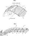
- the figure 1 shows a perspective view of a cooling system 1 for the low pressure turbine casing of a turbomachine according to the state of the art.
- the figures 1 and 2 show a turbomachine casing 2, a cooling system 1 for cooling the casing 2 comprising a plurality of cooling tubes 3, a supply box 4 supplying air to the plurality of cooling tubes, a plurality of mounting brackets 5 for holding the cooling tubes 3 in position around the casing 2.
- the figure 2 shows a partial sectional view of the crankcase cooling system 1 turbomachine according to the state of the art.
- the figure 2 shows more particularly a fixing support under which is fixed a plurality of collars 6, each collar 6 surrounding a cooling tube 3.
- a certain clearance (in the radial direction of the turbine) is provided between the fixing collars or the tubes cooling tube and the external casing casing, in particular to avoid any contact between the parts (mounting collars, cooling tubes, casing) which could cause damage.
- the clearance between the cooling tubes and the outer casing casing must be as small as possible to position the cooling tubes as close as possible to the casing casing and thus promote its cooling.
- the current technical difficulty is to find a good compromise of radial positioning of the cooling tubes to avoid contact of the parts while making the cooling system as efficient as possible thanks to the smallest possible air gap between the cooling tubes and the crankcase.
- a minimum clearance is difficult to guarantee and to control because the housing and the cooling tubes are large diameter parts and the various intermediate parts intervening in the maintenance of the tubes cause an accumulation of tolerances which consequently increase the minimum clearance. eligible.
- the patent US689603 8 describes a ventilation assembly, intended to cool a stator ring of a turbomachine, ends on gas blowing ramps composed of symmetrical half-shells joined by welding at their opposite edges, and united by distributors essentially composed cylindrical coils playing the role of spacers placed between the ramps and welded to them. Finally, the flexible holding means comprising rulers make it possible to complete the assembly of the ramps to the ring.
- Another solution consists in providing an adjustment means configured to make it possible to adjust the relative position of a holding element of a cooling tube with respect to the fixing support.
- an adjustment means configured to make it possible to adjust the relative position of a holding element of a cooling tube with respect to the fixing support.
- such a solution requires fine, long and tedious adjustment when mounting each holding element.
- the object of the present invention is to remedy the drawbacks of the state of the art by proposing a holding device which is easy to mount, does not require adjustment, and which makes it possible to maintain an air gap which is minimal while avoiding contacts between the cooling tubes and the turbomachine casing, despite any expansion of the elements of the turbomachine that may occur during operation.
- the subject of the invention is a device for holding at least one cooling tube of a turbomachine casing cooling system, the casing extending around an axial direction of the turbomachine, the device support comprising a fixing support adapted to be secured to the casing radially externally with respect to the casing, a holding element configured to hold the cooling tube, and a connecting assembly arranged between the holding element and the support fixing, remarkable in that the connecting assembly extends on either side of the fixing support, defining with respect to the fixing support an external part of the connecting assembly radially external to the fixing support and a part internal of the connecting assembly, radially internal to the fixing support, on the side of the casing, the connecting assembly comprising a connecting piece extending through an opening of the fixing support tion from the external part to the internal part, the internal part radially inside the fixing support being secured to the retaining element while the external part comprises an elastic return element biased in compression towards the fixing support by the connecting part, in which the holding element is configured to hold two axially adjacent cooling tubes, and
- the invention also relates to a turbine engine for an aircraft comprising a casing extending around an axial direction of the turbine engine, and a cooling system according to the invention, the cooling system comprising a holding device comprising a fixing support secured to the casing radially externally relative to the casing, at least one cooling tube being arranged radially externally relative to the casing between the casing and the fixing support of the holding device.
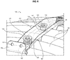
- the figure 3 and 4 illustrate a non-limiting example of a cooling system 100 for a casing 10 of a turbomachine according to one possible embodiment of the invention.
- the cooling system 100 is mounted around the casing 10 of a low pressure turbine.
- the cooling system 100 comprises several cooling tubes 120 mounted around the casing 10.
- the casing 10 extends around an axial direction of the turbomachine, and the cooling tubes 120 extend transversely to this axial direction, and are distributed along the circumference of the housing 10.
- the cooling system 100 also includes holding devices 101 of the cooling tubes 120 for positioning and maintaining the cooling tubes 120 around the housing 10.
- the cooling system 100 in the example shown is an LPTACC cooling device.
- the cooling tubes 120 and the holding device 101 constitute the cooling system 100 of the casing 10 of the low pressure turbine.
- Such a system can also be applied to an LPTC cooling device, or to any other turbomachine crankcase cooling system.
- the two cooling tubes 120 have orifices not visible on the figure 3 and 4 .
- the supply boxes supply relatively cool air with respect to the housing 10 to the cooling tubes 120, which send the air thus available to the outer face 11 of the housing 10 through the orifices (not visible in the figure).
- power boxes are distributed along the circumference of the cooling device.
- each zone of the cooling tubes 120 is supplied with air by a nearby supply box, which makes it possible to have an air flow sent via the orifices of the cooling tubes 120 sufficient whatever the considered zone of the tubes. cooling 120.
- the holding device 101 notably comprises a fixing support 104, here taking the form of a fixing plate, having a main part 105, a first end 106, and a second end (not shown).
- the fixing support 104 is secured to the casing 10 radially externally with respect to the casing 10.
- the ends 106 of the fixing support 104 may have fixing means such as holes 107 accommodating bolts or rivets, in order to allow fixing of the fixing support 104 integrally with the casing, possibly by means of intermediate structures. It is possible for the holes 107 to have an oblong shape, with a greater dimension in one direction (typically in the axial direction), in order to allow free expansion of the casing 10 with respect to the fixing support 104 in this direction.
- the holding device 101 comprises several holding elements 160 for the cooling tube 120.
- Each holding element 160 allows the attachment of at least one cooling tube 120.
- the holding element 160 is for example a holding support or a preformed retaining plate.
- the holding element 160 extends around a part of the circumference of a cooling tube 120, typically in the shape of a half-ring, and leaves free another part of the circumference of the cooling tube 120 intended to face the casing 10 of the turbomachine.
- the holding element 160 partially covers the periphery of the cooling tubes 120 and only a radially outer part of the cooling tubes 120, in particular the periphery of the cooling tubes 120 facing the mounting bracket 104. It is at this level that the holding element 160 is secured to the cooling tube 120, for example by brazing.
- the holding element can thus have a central part 161 that is generally planar and two portions 162, 163 in the shape of half-rings intended to match and to cover, at least partially, the annular shape of two adjacent cooling tubes 120 .
- the cooling tubes 120 are secured to the holding element 160 for example by brazing.
- the holding element 160 advantageously makes it possible to secure the cooling tubes at the level of a radially outer part of the cooling tubes, that is to say on the fixing support 104 side, in particular so as to avoid the presence of a part or an additional element between the cooling tube 120 and the casing 10, and so as to be able to bring the cooling tubes 120 closer to the casing 10 for the optimization of the cooling of the latter.
- the holding element 160 makes it possible to secure two cooling tubes 120 by means of the same and single holding element 160.
- two tubes are held and positioned cooling tubes 120 axially adjacent by making only one opening 108 in the mounting bracket 104.
- the mounting bracket 104 will have fewer openings 108 and less hanging zone than a mounting bracket according to the state of the art.
- it is also envisaged to produce a retaining element making it possible to individually secure a cooling tube so as to improve the precision of adjustment of the radial position of the cooling tubes 120 with respect to the casing 10.
- the holding device 101 also comprises a connection assembly 140 between the holding element 101 and the fixing support 104, the function of which is to provide the mechanical connection between the holding element 101 and the fixing support 104.
- the retaining element 101 must support at least one cooling tube 120 radially above the casing 10 leaving a clearance J between a cooling tube 120 and the outer surface 11 of the casing 10, and must therefore to do this be supported by mounting bracket 104.
- the connecting assembly 140 extends on either side of the mounting bracket 104, through the opening 108, which defines with respect to the mounting bracket 104 an outer part 141 of the connecting assembly 140, radially external to the fixing support 104, and an internal part 142 of the connection assembly, radially internal to the fixing support 104, on the side of the casing 10 of the turbomachine.
- the link assembly 140 includes a link piece 150 extending through the opening 108 of the mounting bracket 104, from the outer part 141 to the inner part 142 of the link assembly 140.
- the inner part 142 is integral with the retaining element 160.
- the connecting piece 150 can be a screw comprising a threaded body, and the internal part 142 can comprise a tapped receiving element 144 in which the threaded body of the the screw constituting the connecting element 150.
- the connecting piece 150 can pass through a hole in the holding element 160 and thus extend from one side radially inside the holding element 160, i.e. say in the direction of the housing 10.
- the receiving element 144 can then be arranged on the side radially internal to the holding element 160, so as to hold the holding element 160.
- the receiving element 144 can typically be a nut screwed onto one end of the screw 150, bearing against the radial face internal element of the holding element 160.
- the internal part 142 of the connecting piece is placed between two axially adjacent cooling tubes 120 .
- one end of the connecting piece 150 extends from the side radially internal to the retaining element 160 between the two axially adjacent cooling tubes 120 secured to the retaining element 160.
- the hole in the retaining element 160 which is crossed by the connecting piece is then provided in the central part 161 which joins the two portions 162, 163 in the form of half-rings.
- the link assembly 140 includes a sleeve 145 extending into the outer portion of the link assembly.
- the sleeve 145 has in its center a passage in which the connecting piece 150 extends.
- the sleeve 145 has a circular section.
- the sleeve 145 forms an abutment in the radially internal direction for the connecting piece 150.
- the connecting piece 150 has at its radially outer end a head 151 defined by an enlarged section, and the sleeve 145 has a shoulder 146 forming a stop in the radially internal direction for the head 151 of the connecting piece.
- the sleeve 145 comprises a first part having a wide section allowing the passage of the connecting piece 150, including its head 151, and preferably also allowing the passage of a tool for installing the connecting piece. 150, such as for example a tightening key engaged with the head 151.
- This first part is extended radially inwards by a second part having a narrow section, allowing the passage of one end of the connecting piece 150 but prohibiting the passage of the head 151, the transition between the first part and the second part of the sleeve 145 forming the shoulder 146.
- the second part of the sleeve 145 passes through the opening 108, thus protecting the connecting part 150.
- the second part of the sleeve 145 can then come into contact with the retaining part 160 on its radially outer face.
- the connecting piece 150 When fitting the connecting assembly 140, it is therefore sufficient to introduce the connecting piece 150 into the socket until the head 151 is in abutment against the shoulder 146. In the case where the connecting piece is a screw, this abutment can thus mark the screwing limit by naturally limiting it. It is therefore a very simple assembly requiring no adjustment. It is also possible to apply a predetermined tightening torque, for example the same for all the parts, which is not an adjustment torque. Alternatively, it would be possible to provide that the sleeve 145 and the connecting piece 150 form a single piece. Preferably, however, the sleeve 145 and the connecting piece 150 are separate.
- the connecting assembly 140 comprises in its outer part 141 an elastic return element biased in compression towards the fixing support 104 by the connecting part 150.
- the elastic return element preferably takes the form of a spring 170, as depicted on the figure 3 and 4 .
- the spring 170 is preferably disposed around the sleeve 145.
- the sleeve 145 forms an abutment in the radially outer direction for the spring 170.
- the sleeve has a flange 147 projecting in a direction opposite to the center of the sleeve 145 through which the connecting piece 150 passes, and the spring 170 is arranged between this flange 147 and the fixing support 104.
- this flange 147 extending from the outer end of the sleeve 145.
- the spring 170 is compressed in the direction of the mounting bracket 104 by the connecting piece 150.
- the action of the spring 170 makes it possible to guarantee that is exerted on the mounting bracket 104 a pressure allowing the plating of the connection assembly 140 on this fixing support 104, while authorizing a movement between the connection assembly 140 and this fixing support 104.
- the constant plating even during the movement makes it possible to guarantee the maintenance a game J between a cooling tube 120 and the housing 10, which can therefore be considered minimal.
- opening 108 in the fixing support 104 has a section greater than the section of the part of the connection assembly 140 passing through this opening 108, such that linkage assembly 140 is movable relative to mounting bracket 104, allowing free circumferential and/or radial expansion of cooling tubes 120 relative to mounting bracket 104.
- opening 108 has an oblong or oval cross-section, that is, with a larger dimension in one direction than in other directions.
- the opening of the fixing support 104 has in the circumferential direction of the turbomachine a dimension at least 1.5 times greater than its dimension in a direction (eg typically in the axial direction) perpendicular to the circumferential direction of the turbomachinery.
- This opening 108 thus allows movements of the sleeve 145 which passes through it in a plane orthogonal to the axis of the opening 108 and therefore also movements of the holding element 160 which is secured to the sleeve 145 by the part connecting 150. These movements allow the differential expansion of the cooling tubes 120 relative to the housing 10 during operation.
- the holding device may comprise an external support element 155 in the external part of the connection assembly 140, placed against the external face of the fixing support 104, on which the spring 170 presses.
- 155 is for example a metal washer.
- the external support element 155 is not integral with the sleeve 145.
- the external support element is not fixed to the fixing support 104, and therefore allows by its sliding on the surface of the fixing support 104 , the movement of the connection assembly 140 relative to the mounting bracket 104.
- An internal support element 156 may be present in the internal part 142 of the connection assembly, placed against the internal face of the fixing support 104 and separating the holding element 160 and said internal face of the fixing support 104.
- the internal support element 156 comprises an orifice facing the opening 108 of the fixing support 104.
- the internal support element 156 can for example be a metal washer.
- the internal support element 156 is not fixed to the fixing support 104, and therefore allows, by its sliding on the internal surface of the fixing support 104, the movement of the assembly 140 with respect to the mounting bracket 104.
- the internal support element 156 makes it possible to prevent the wear of the holding element 160 against the internal surface of the mounting bracket 104. It also makes it possible to guarantee a spacing of a determined distance between the retaining element 160 and the fixing support 104, avoiding providing a margin of tolerance for the clearance J between the cooling tubes 120 and the outer face 11 of the casing 10.
- the external support element 155 and the internal support element 156 can be used as possible adjustment variables (by their respective thicknesses or by their mere presence or absence) to obtain the desired clearance J. They can thus be used to rectify the shapes of other elements of the cooling system 100 which would impact the clearance J.
- the thickness of the external support element 155 and/or the internal support element 156 can be adapted to any variations in the distance between the mounting bracket 104 and the outer face 11 of the casing 10, in order to compensate for them. These elements can also be used as adjustment wedges during assembly if necessary.
- the holding elements 160 cooling tubes 120 are fixed to the cooling tubes 120, for example by brazing.
- various elements can be pre-assembled on the fixing support 104 before mounting the latter on the casing 10. It is for example possible to arrange the external support elements 155 therein with the orifices facing the opening 108, then to set up the springs 170 on these external support elements 155.
- the sleeves 145 are then introduced into the openings 108 so that the springs are compressed by the flanges 147 of the sleeves 145.
- the connecting pieces 150 are then put in place in the sockets 145, and come into engagement with the clamping element 142 of the internal part of the connecting assembly 140. The tightening of the connecting pieces 150 makes the socket 145 integral with the holding element 160.
- the connecting piece 150 is a screw
- the head 151 comes into abutment against the shoulder 146 of the sleeve 145.
- the sleeve 145 is then driven in the radially internal direction, through the opening 108, until it comes in abutment against the holding element 160. It is then no longer possible to tighten the connecting piece 150.
- the cooling system 100 consisting of the holding device 101 and the cooling tubes 120 can then be put in place on the casing 10, for example by using fixing means such as holes 107 present at the ends 106 of the fixing support 104.
- the installation of the retaining device 101 therefore does not require any particular adjustment to ensure an appropriate clearance J (in the radial direction of the turbine) between a cooling tube 120 and the outer face 11 of the casing 10.
- the clearance J is determined by the dimensions of the constituent elements of the holding device 101.
- the assembly of the holding device 101 is therefore greatly simplified. It suffices, for example, to screw the connecting piece 150 until it locks.
- the absence of the retaining element 160 between the cooling tube 120 and the casing 10 also means that a less thickness is to be taken into account for the dimensioning of the cooling system 100, facilitating this dimensioning and making it more precise, again making it possible to provide a minimum clearance J.
Landscapes
- Engineering & Computer Science (AREA)
- General Engineering & Computer Science (AREA)
- Mechanical Engineering (AREA)
- Chemical & Material Sciences (AREA)
- Combustion & Propulsion (AREA)
- Physics & Mathematics (AREA)
- Fluid Mechanics (AREA)
- Turbine Rotor Nozzle Sealing (AREA)
- Clamps And Clips (AREA)
- Structures Of Non-Positive Displacement Pumps (AREA)
Claims (12)
- Haltevorrichtung (101) mindestens einer Kühlleitung (120) eines Kühlsystems (100) eines Turbotriebwerkgehäuses (10), wobei sich die Haltevorrichtung (101) um eine Achse herum erstreckt, die eine axiale Richtung definiert, und eine Befestigungshalterung (104) beinhaltet, die angepasst ist, um fest mit dem Gehäuse (10) verbunden zu werden, und radial außerhalb in Bezug auf das Gehäuse (10) angeordnet ist, ein Halteelement (160), das konfiguriert ist, um die Kühlleitung (120) zu halten, und eine Verbindungseinheit (140), die das Halteelement (160) und die Befestigungshalterung (104) verbindet,
dadurch gekennzeichnet, dass sich die Verbindungseinheit (140) beiderseits der Befestigungshalterung (104) erstreckt, in Bezug auf die Befestigungshalterung (104) ein Außenteil (141) der Verbindungseinheit, radial außerhalb der Befestigungshalterung (104), und ein Innenteil (142) der Verbindungseinheit, radial innerhalb der Befestigungshalterung (104) definiert, wobei die Verbindungseinheit (140) auf Seiten des Gehäuses (10) ein Verbindungsstück (150) umfasst, das sich durch eine Öffnung (108) der Befestigungshalterung (104) hindurch, vom Außenteil (141) bis zum Innenteil (142) erstreckt, wobei das Innenteil (142) radial innerhalb der Befestigungshalterung (104) fest mit dem Halteelement (160) verbunden ist, während das Außenteil (141) ein elastisches Rückstellelement (170) umfasst, das in Richtung der Befestigungshalterung (104) durch das Verbindungsstück (150) druckbeansprucht ist, wobei das Halteelement (160) konfiguriert ist, um zwei axial benachbarte Kühlleitungen (120) zu halten, und das Innenteil (142) der Verbindungseinheit zwischen zwei axial benachbarten Kühlleitungen (120) angeordnet ist. - Haltevorrichtung nach Anspruch 1, wobei die Öffnung (108) der Befestigungshalterung (104) einen Querschnitt aufweist, der größer als der Querschnitt des Teils der Verbindungseinheit (140) ist, der diese Öffnung (108) durchquert, um eine Bewegung zwischen der Verbindungseinheit (140) und der Halterung (104) zu erlauben, wobei die Öffnung (108) der Befestigungshalterung (104) eine längliche Form aufweist, wobei die Öffnung (108) der Befestigungshalterung (104) in der Umfangsrichtung eine Abmessung mindestens 1,5 Mal größer als ihre Abmessung in der axialen Richtung aufweist.
- Haltevorrichtung nach einem der Ansprüche 1 bis 2, eine Hülse (145) umfassend, die sich in dem Außenteil (141) der Verbindungseinheit (160) erstreckt, wobei die Hülse einen Anschlag in der radial inneren Richtung für das Verbindungsstück (150) bildet, und einen Anschlag in der radial äußeren Richtung für das elastische Rückstellelement (170) bildet, wobei das Verbindungsstück (150) an seinem radial äußeren Ende einen Kopf (151) aufweist, der durch einen erweiterten Querschnitt definiert wird, und die Hülse (145) einen Ansatz (146) aufweist, der einen Anschlag in der radial inneren Richtung für den Kopf des Verbindungsstücks (150) bildet, und wobei die Hülse einen Kragen (147) aufweist, und das elastische Rückstellelement (170) zwischen diesem Kragen (147) und der Befestigungshalterung (104) angeordnet ist.
- Haltevorrichtung nach einem der Ansprüche 1 bis 3, wobei das Verbindungsstück (150) eine Schraube ist, die einen Gewindekörper umfasst, und das Innenteil ein Aufnahmeelement mit Innengewinde (144) umfasst, das auf der radial inneren Seite zum Halteelement (160) angeordnet ist, und in das der Gewindekörper der Schraube geschraubt ist.
- Haltevorrichtung nach einem der Ansprüche 1 bis 4, umfassend ein äußeres Auflageelement (155) in dem Außenteil (141) der Verbindungseinheit (140), das an der Außenseite der Befestigungshalterung (104) angeordnet ist, an der das elastische Rückstellelement (170) anliegt.
- Haltevorrichtung nach einem der Ansprüche 1 bis 5, umfassend ein inneres Auflageelement (156) im Innenteil (142) der Verbindungseinheit (140), das an der Innenseite der Befestigungshalterung (104) angeordnet ist, und das Halteelement (160) und die Innenseite der Befestigungshalterung (104) trennt.
- Haltevorrichtung nach einem der Ansprüche 1 bis 6, wobei das Halteelement (160) die Umrandung der Kühlleitungen (120) teilweise abdeckt, und sich um einen Teil des Umfangs einer Kühlleitung (120) entsprechend einer Habringform erstreckt.
- Haltevorrichtung nach einem der Ansprüche 1 bis 7, wobei sich das Halteelement (160) um einen Teil des Umfangs einer Kühlleitung herum erstreckt, und einen anderen Teil des Umfangs der Kühlleitung freilässt, der dazu bestimmt ist, in Richtung des Gehäuses (10) zu weisen.
- Haltevorrichtung nach einem der Ansprüche 1 bis 8, wobei das Halteelement ein im Allgemeinen flacher Mittelteil (161) und zwei Abschnitte (162, 163) in Form von Halbringen aufweist, die dazu bestimmt sind, sich an die Ringform der beiden benachbarten Kühlleitungen (120) anzulegen und diese zu bedecken.
- Haltevorrichtung nach Anspruch 9, wobei ein Loch des Halteelements (160), das von dem Verbindungsstück (150) durchquert wird, in dem Mittelteil (161) eingerichtet ist, der die beiden Abschnitte (162, 163) in Form von Halbringen vereinigt.
- Kühlsystem (100) eines Turbotriebwerkgehäuses, umfassend:- eine Vielzahl von Kühlleitungen (120),- eine Haltevorrichtung (101) nach einem der vorstehenden Ansprüche, wobei das Halteelement (160) zwei axial benachbarte Kühlleitungen hält.
- Turbotriebwerk für ein Luftfahrzeug, umfassend ein Gehäuse (10), das sich um eine axiale Richtung des Turbotriebwerks herum erstreckt, und ein Kühlsystem (100) nach dem vorstehenden Anspruch, wobei die Befestigungshalterung (104) radial außerhalb in Bezug auf das Gehäuse (10) fest mit dem Gehäuse (10) verbunden ist, wobei die Vielzahl von Kühlleitungen (120), radial außerhalb in Bezug auf das Gehäuse (10), zwischen dem Gehäuse (10) und der Befestigungshalterung (104) angeordnet sind.
Applications Claiming Priority (1)
| Application Number | Priority Date | Filing Date | Title |
|---|---|---|---|
| FR1872452A FR3089560B1 (fr) | 2018-12-06 | 2018-12-06 | Dispositif de maintien d'un tube de refroidissement pour carter de turbomachine |
Publications (2)
| Publication Number | Publication Date |
|---|---|
| EP3663534A1 EP3663534A1 (de) | 2020-06-10 |
| EP3663534B1 true EP3663534B1 (de) | 2022-11-09 |
Family
ID=67383803
Family Applications (1)
| Application Number | Title | Priority Date | Filing Date |
|---|---|---|---|
| EP19212270.3A Active EP3663534B1 (de) | 2018-12-06 | 2019-11-28 | Haltevorrichtung einer kühlleitung für turbotriebwerkgehäuse |
Country Status (4)
| Country | Link |
|---|---|
| US (1) | US11555405B2 (de) |
| EP (1) | EP3663534B1 (de) |
| CN (1) | CN111287808B (de) |
| FR (1) | FR3089560B1 (de) |
Cited By (1)
| Publication number | Priority date | Publication date | Assignee | Title |
|---|---|---|---|---|
| WO2025088276A1 (fr) | 2023-10-26 | 2025-05-01 | Safran Aircraft Engines | Dispositif de refroidissement par jets d'air d'un carter de turbine et turbomachine comportant un tel dispositif |
Families Citing this family (2)
| Publication number | Priority date | Publication date | Assignee | Title |
|---|---|---|---|---|
| FR3127012B1 (fr) * | 2021-09-14 | 2024-11-08 | Safran Aircraft Engines | Douille pour boitier de distribution d’air de turbomachine |
| FR3137406A1 (fr) * | 2022-07-04 | 2024-01-05 | Safran Aircraft Engines | Carter de turbine de turboreacteur equipe de dispositifs mobiles de fixation de tubes de refroidissement |
Family Cites Families (13)
| Publication number | Priority date | Publication date | Assignee | Title |
|---|---|---|---|---|
| US5271588A (en) * | 1992-07-17 | 1993-12-21 | General Electric Company | Multi-piece tube clamp |
| FR2816352B1 (fr) * | 2000-11-09 | 2003-01-31 | Snecma Moteurs | Ensemble de ventilation d'un anneau de stator |
| US9341074B2 (en) * | 2012-07-25 | 2016-05-17 | General Electric Company | Active clearance control manifold system |
| FR2995022B1 (fr) * | 2012-09-04 | 2017-11-24 | Snecma | Dispositif de fixation d'un systeme de refroidissement pour carter de turboreacteur d'aeronef |
| FR3002590B1 (fr) * | 2013-02-26 | 2015-04-03 | Snecma | Dispositif de refroidissement pour carter de turboreacteur d'aeronef comportant un dispositif de maintien |
| US20150233496A1 (en) * | 2014-02-19 | 2015-08-20 | Entertainment Structural Products | Multi-Connection Truss Pick |
| FR3021700B1 (fr) | 2014-05-27 | 2016-07-01 | Snecma | Dispositif de maintien d'un tube de refroidissement pour carter de turboreacteur |
| FR3040429B1 (fr) * | 2015-08-27 | 2019-06-07 | Safran Aircraft Engines | Dispositif de fixation des rampes de refroidissement par jets d'air du carter d'une turbine de turbomachine |
| FR3058460B1 (fr) * | 2016-11-08 | 2018-11-09 | Safran Aircraft Engines | Ensemble de raccordement pour le refroidissement d'une turbine de turbomachine |
| FR3073007B1 (fr) * | 2017-10-27 | 2019-09-27 | Safran Aircraft Engines | Dispositif de maintien d'un tube de refroidissement pour carter de turbomachine |
| FR3077097B1 (fr) * | 2018-01-22 | 2020-08-07 | Safran Aircraft Engines | Dispositif de refroidissement pour une turbine d'une turbomachine |
| FR3079560B1 (fr) * | 2018-04-03 | 2020-10-09 | Safran Aircraft Engines | Dispositif de refroidissement pour une turbine d'une turbomachine |
| FR3079874B1 (fr) * | 2018-04-09 | 2020-03-13 | Safran Aircraft Engines | Dispositif de refroidissement pour une turbine d'une turbomachine |
-
2018
- 2018-12-06 FR FR1872452A patent/FR3089560B1/fr not_active Expired - Fee Related
-
2019
- 2019-11-28 EP EP19212270.3A patent/EP3663534B1/de active Active
- 2019-12-05 US US16/704,031 patent/US11555405B2/en active Active
- 2019-12-05 CN CN201911232089.3A patent/CN111287808B/zh active Active
Cited By (2)
| Publication number | Priority date | Publication date | Assignee | Title |
|---|---|---|---|---|
| WO2025088276A1 (fr) | 2023-10-26 | 2025-05-01 | Safran Aircraft Engines | Dispositif de refroidissement par jets d'air d'un carter de turbine et turbomachine comportant un tel dispositif |
| FR3154755A1 (fr) * | 2023-10-26 | 2025-05-02 | Safran Aircraft Engines | Dispositif de refroidissement par jets d’air d’un carter de turbine et turbomachine comportant un tel dispositif |
Also Published As
| Publication number | Publication date |
|---|---|
| US11555405B2 (en) | 2023-01-17 |
| CN111287808A (zh) | 2020-06-16 |
| EP3663534A1 (de) | 2020-06-10 |
| US20200182058A1 (en) | 2020-06-11 |
| FR3089560B1 (fr) | 2021-01-22 |
| FR3089560A1 (fr) | 2020-06-12 |
| CN111287808B (zh) | 2022-05-24 |
Similar Documents
| Publication | Publication Date | Title |
|---|---|---|
| EP3663534B1 (de) | Haltevorrichtung einer kühlleitung für turbotriebwerkgehäuse | |
| EP3701128B1 (de) | Rückhaltevorrichtung für ein kühlrohr für ein turbomaschinengehäuse | |
| FR3018548A1 (fr) | Turboreacteur a conduit de decharge | |
| EP3230602B1 (de) | Ring zur steuerung einer phase von leitschaufeln mit variablen einstellungen für einen turbinenmotor | |
| EP3074611B1 (de) | Vorrichtung zur zentrierung und führung der rotation einer turbinenmotorwelle mit verbessertem mittel zum zurückhalten des äusseren lagerrings | |
| EP3775501B1 (de) | Kühlvorrichtung für eine turbine einer turbomaschine | |
| EP3775498B1 (de) | Kühlvorrichtung für eine turbine eines turbinenmotors | |
| FR2949518A1 (fr) | Compresseur de turbomachine ayant des injecteurs d'air | |
| EP3084140B1 (de) | Führungsarm für gegenstände mit länglicher form, insbesondere für eine turbomaschine | |
| FR3077097A1 (fr) | Dispositif de refroidissement pour une turbine d'une turbomachine | |
| EP3204654A1 (de) | Zusammenbau von zwei teilen mit abnehmbarem zentriersitz für ein flugzeugturbinentriebwerk | |
| EP3638891B1 (de) | Unverlierbare schraubendüse | |
| FR3026827A1 (fr) | Chambre de combustion de turbomachine | |
| EP1538306A1 (de) | Bindungsvorrichtung zwischen einer Leitschaufel und ihrer Kühlmittelkammer in einer Turbomaschine | |
| EP4010563B1 (de) | Prallkühlvorrichtung für ein turbomaschinen-aussengehäuse und turbomaschine mit entsprechender vorrichtung | |
| FR2942638A1 (fr) | Secteur angulaire de redresseur pour compresseur de turbomachine | |
| FR2988436A1 (fr) | Dispositif de guidage d'une bougie d'allumage | |
| FR3051014A1 (fr) | Ensemble pour turbomachine comprenant un distributeur, un element de structure de turbomachine, et un dispositif de fixation | |
| WO2018002480A1 (fr) | Ensemble de fixation d'un distributeur a un element de structure d'une turbomachine | |
| EP3384193B1 (de) | Vorrichtung zur begrenzung des lösens einer mutter in einem turbinenmotor | |
| FR3119646A1 (fr) | Rotor de turbomachine | |
| FR3081533A1 (fr) | Dispositif de fixation et de maintien d'au moins un harnais electrique dans une turbomachine | |
| FR3092616A1 (fr) | Dispositif de fixation et de maintien d’au moins une conduite sur un élément de turbomachine | |
| FR2944089A1 (fr) | Accrochage de chambre annulaire de combustion | |
| FR3105996A1 (fr) | Organe de verrouillage destiné à l’assemblage d’une première pièce et d’une seconde pièce d’une turbomachine |
Legal Events
| Date | Code | Title | Description |
|---|---|---|---|
| PUAI | Public reference made under article 153(3) epc to a published international application that has entered the european phase |
Free format text: ORIGINAL CODE: 0009012 |
|
| STAA | Information on the status of an ep patent application or granted ep patent |
Free format text: STATUS: REQUEST FOR EXAMINATION WAS MADE |
|
| 17P | Request for examination filed |
Effective date: 20191128 |
|
| AK | Designated contracting states |
Kind code of ref document: A1 Designated state(s): AL AT BE BG CH CY CZ DE DK EE ES FI FR GB GR HR HU IE IS IT LI LT LU LV MC MK MT NL NO PL PT RO RS SE SI SK SM TR |
|
| AX | Request for extension of the european patent |
Extension state: BA ME |
|
| GRAP | Despatch of communication of intention to grant a patent |
Free format text: ORIGINAL CODE: EPIDOSNIGR1 |
|
| STAA | Information on the status of an ep patent application or granted ep patent |
Free format text: STATUS: GRANT OF PATENT IS INTENDED |
|
| GRAS | Grant fee paid |
Free format text: ORIGINAL CODE: EPIDOSNIGR3 |
|
| INTG | Intention to grant announced |
Effective date: 20220906 |
|
| GRAA | (expected) grant |
Free format text: ORIGINAL CODE: 0009210 |
|
| STAA | Information on the status of an ep patent application or granted ep patent |
Free format text: STATUS: THE PATENT HAS BEEN GRANTED |
|
| AK | Designated contracting states |
Kind code of ref document: B1 Designated state(s): AL AT BE BG CH CY CZ DE DK EE ES FI FR GB GR HR HU IE IS IT LI LT LU LV MC MK MT NL NO PL PT RO RS SE SI SK SM TR |
|
| REG | Reference to a national code |
Ref country code: GB Ref legal event code: FG4D Free format text: NOT ENGLISH |
|
| REG | Reference to a national code |
Ref country code: CH Ref legal event code: EP Ref country code: AT Ref legal event code: REF Ref document number: 1530505 Country of ref document: AT Kind code of ref document: T Effective date: 20221115 |
|
| REG | Reference to a national code |
Ref country code: DE Ref legal event code: R096 Ref document number: 602019021655 Country of ref document: DE |
|
| REG | Reference to a national code |
Ref country code: IE Ref legal event code: FG4D Free format text: LANGUAGE OF EP DOCUMENT: FRENCH |
|
| REG | Reference to a national code |
Ref country code: LT Ref legal event code: MG9D |
|
| REG | Reference to a national code |
Ref country code: NL Ref legal event code: MP Effective date: 20221109 |
|
| REG | Reference to a national code |
Ref country code: AT Ref legal event code: MK05 Ref document number: 1530505 Country of ref document: AT Kind code of ref document: T Effective date: 20221109 |
|
| PG25 | Lapsed in a contracting state [announced via postgrant information from national office to epo] |
Ref country code: SE Free format text: LAPSE BECAUSE OF FAILURE TO SUBMIT A TRANSLATION OF THE DESCRIPTION OR TO PAY THE FEE WITHIN THE PRESCRIBED TIME-LIMIT Effective date: 20221109 Ref country code: PT Free format text: LAPSE BECAUSE OF FAILURE TO SUBMIT A TRANSLATION OF THE DESCRIPTION OR TO PAY THE FEE WITHIN THE PRESCRIBED TIME-LIMIT Effective date: 20230309 Ref country code: NO Free format text: LAPSE BECAUSE OF FAILURE TO SUBMIT A TRANSLATION OF THE DESCRIPTION OR TO PAY THE FEE WITHIN THE PRESCRIBED TIME-LIMIT Effective date: 20230209 Ref country code: LT Free format text: LAPSE BECAUSE OF FAILURE TO SUBMIT A TRANSLATION OF THE DESCRIPTION OR TO PAY THE FEE WITHIN THE PRESCRIBED TIME-LIMIT Effective date: 20221109 Ref country code: FI Free format text: LAPSE BECAUSE OF FAILURE TO SUBMIT A TRANSLATION OF THE DESCRIPTION OR TO PAY THE FEE WITHIN THE PRESCRIBED TIME-LIMIT Effective date: 20221109 Ref country code: ES Free format text: LAPSE BECAUSE OF FAILURE TO SUBMIT A TRANSLATION OF THE DESCRIPTION OR TO PAY THE FEE WITHIN THE PRESCRIBED TIME-LIMIT Effective date: 20221109 Ref country code: AT Free format text: LAPSE BECAUSE OF FAILURE TO SUBMIT A TRANSLATION OF THE DESCRIPTION OR TO PAY THE FEE WITHIN THE PRESCRIBED TIME-LIMIT Effective date: 20221109 |
|
| PG25 | Lapsed in a contracting state [announced via postgrant information from national office to epo] |
Ref country code: RS Free format text: LAPSE BECAUSE OF FAILURE TO SUBMIT A TRANSLATION OF THE DESCRIPTION OR TO PAY THE FEE WITHIN THE PRESCRIBED TIME-LIMIT Effective date: 20221109 Ref country code: PL Free format text: LAPSE BECAUSE OF FAILURE TO SUBMIT A TRANSLATION OF THE DESCRIPTION OR TO PAY THE FEE WITHIN THE PRESCRIBED TIME-LIMIT Effective date: 20221109 Ref country code: LV Free format text: LAPSE BECAUSE OF FAILURE TO SUBMIT A TRANSLATION OF THE DESCRIPTION OR TO PAY THE FEE WITHIN THE PRESCRIBED TIME-LIMIT Effective date: 20221109 Ref country code: IS Free format text: LAPSE BECAUSE OF FAILURE TO SUBMIT A TRANSLATION OF THE DESCRIPTION OR TO PAY THE FEE WITHIN THE PRESCRIBED TIME-LIMIT Effective date: 20230309 Ref country code: HR Free format text: LAPSE BECAUSE OF FAILURE TO SUBMIT A TRANSLATION OF THE DESCRIPTION OR TO PAY THE FEE WITHIN THE PRESCRIBED TIME-LIMIT Effective date: 20221109 Ref country code: GR Free format text: LAPSE BECAUSE OF FAILURE TO SUBMIT A TRANSLATION OF THE DESCRIPTION OR TO PAY THE FEE WITHIN THE PRESCRIBED TIME-LIMIT Effective date: 20230210 |
|
| PG25 | Lapsed in a contracting state [announced via postgrant information from national office to epo] |
Ref country code: NL Free format text: LAPSE BECAUSE OF FAILURE TO SUBMIT A TRANSLATION OF THE DESCRIPTION OR TO PAY THE FEE WITHIN THE PRESCRIBED TIME-LIMIT Effective date: 20221109 |
|
| REG | Reference to a national code |
Ref country code: CH Ref legal event code: PL |
|
| REG | Reference to a national code |
Ref country code: BE Ref legal event code: MM Effective date: 20221130 |
|
| PG25 | Lapsed in a contracting state [announced via postgrant information from national office to epo] |
Ref country code: SM Free format text: LAPSE BECAUSE OF FAILURE TO SUBMIT A TRANSLATION OF THE DESCRIPTION OR TO PAY THE FEE WITHIN THE PRESCRIBED TIME-LIMIT Effective date: 20221109 Ref country code: RO Free format text: LAPSE BECAUSE OF FAILURE TO SUBMIT A TRANSLATION OF THE DESCRIPTION OR TO PAY THE FEE WITHIN THE PRESCRIBED TIME-LIMIT Effective date: 20221109 Ref country code: LI Free format text: LAPSE BECAUSE OF NON-PAYMENT OF DUE FEES Effective date: 20221130 Ref country code: EE Free format text: LAPSE BECAUSE OF FAILURE TO SUBMIT A TRANSLATION OF THE DESCRIPTION OR TO PAY THE FEE WITHIN THE PRESCRIBED TIME-LIMIT Effective date: 20221109 Ref country code: DK Free format text: LAPSE BECAUSE OF FAILURE TO SUBMIT A TRANSLATION OF THE DESCRIPTION OR TO PAY THE FEE WITHIN THE PRESCRIBED TIME-LIMIT Effective date: 20221109 Ref country code: CZ Free format text: LAPSE BECAUSE OF FAILURE TO SUBMIT A TRANSLATION OF THE DESCRIPTION OR TO PAY THE FEE WITHIN THE PRESCRIBED TIME-LIMIT Effective date: 20221109 Ref country code: CH Free format text: LAPSE BECAUSE OF NON-PAYMENT OF DUE FEES Effective date: 20221130 |
|
| REG | Reference to a national code |
Ref country code: DE Ref legal event code: R097 Ref document number: 602019021655 Country of ref document: DE |
|
| PG25 | Lapsed in a contracting state [announced via postgrant information from national office to epo] |
Ref country code: SK Free format text: LAPSE BECAUSE OF FAILURE TO SUBMIT A TRANSLATION OF THE DESCRIPTION OR TO PAY THE FEE WITHIN THE PRESCRIBED TIME-LIMIT Effective date: 20221109 Ref country code: LU Free format text: LAPSE BECAUSE OF NON-PAYMENT OF DUE FEES Effective date: 20221128 Ref country code: AL Free format text: LAPSE BECAUSE OF FAILURE TO SUBMIT A TRANSLATION OF THE DESCRIPTION OR TO PAY THE FEE WITHIN THE PRESCRIBED TIME-LIMIT Effective date: 20221109 |
|
| PLBE | No opposition filed within time limit |
Free format text: ORIGINAL CODE: 0009261 |
|
| STAA | Information on the status of an ep patent application or granted ep patent |
Free format text: STATUS: NO OPPOSITION FILED WITHIN TIME LIMIT |
|
| 26N | No opposition filed |
Effective date: 20230810 |
|
| PG25 | Lapsed in a contracting state [announced via postgrant information from national office to epo] |
Ref country code: IE Free format text: LAPSE BECAUSE OF NON-PAYMENT OF DUE FEES Effective date: 20221128 |
|
| PG25 | Lapsed in a contracting state [announced via postgrant information from national office to epo] |
Ref country code: SI Free format text: LAPSE BECAUSE OF FAILURE TO SUBMIT A TRANSLATION OF THE DESCRIPTION OR TO PAY THE FEE WITHIN THE PRESCRIBED TIME-LIMIT Effective date: 20221109 Ref country code: BE Free format text: LAPSE BECAUSE OF NON-PAYMENT OF DUE FEES Effective date: 20221130 |
|
| PG25 | Lapsed in a contracting state [announced via postgrant information from national office to epo] |
Ref country code: HU Free format text: LAPSE BECAUSE OF FAILURE TO SUBMIT A TRANSLATION OF THE DESCRIPTION OR TO PAY THE FEE WITHIN THE PRESCRIBED TIME-LIMIT; INVALID AB INITIO Effective date: 20191128 |
|
| PG25 | Lapsed in a contracting state [announced via postgrant information from national office to epo] |
Ref country code: CY Free format text: LAPSE BECAUSE OF FAILURE TO SUBMIT A TRANSLATION OF THE DESCRIPTION OR TO PAY THE FEE WITHIN THE PRESCRIBED TIME-LIMIT Effective date: 20221109 |
|
| PG25 | Lapsed in a contracting state [announced via postgrant information from national office to epo] |
Ref country code: MK Free format text: LAPSE BECAUSE OF FAILURE TO SUBMIT A TRANSLATION OF THE DESCRIPTION OR TO PAY THE FEE WITHIN THE PRESCRIBED TIME-LIMIT Effective date: 20221109 Ref country code: IT Free format text: LAPSE BECAUSE OF FAILURE TO SUBMIT A TRANSLATION OF THE DESCRIPTION OR TO PAY THE FEE WITHIN THE PRESCRIBED TIME-LIMIT Effective date: 20221109 |
|
| PG25 | Lapsed in a contracting state [announced via postgrant information from national office to epo] |
Ref country code: MC Free format text: LAPSE BECAUSE OF FAILURE TO SUBMIT A TRANSLATION OF THE DESCRIPTION OR TO PAY THE FEE WITHIN THE PRESCRIBED TIME-LIMIT Effective date: 20221109 |
|
| PG25 | Lapsed in a contracting state [announced via postgrant information from national office to epo] |
Ref country code: MC Free format text: LAPSE BECAUSE OF FAILURE TO SUBMIT A TRANSLATION OF THE DESCRIPTION OR TO PAY THE FEE WITHIN THE PRESCRIBED TIME-LIMIT Effective date: 20221109 |
|
| PG25 | Lapsed in a contracting state [announced via postgrant information from national office to epo] |
Ref country code: BG Free format text: LAPSE BECAUSE OF FAILURE TO SUBMIT A TRANSLATION OF THE DESCRIPTION OR TO PAY THE FEE WITHIN THE PRESCRIBED TIME-LIMIT Effective date: 20221109 |
|
| PG25 | Lapsed in a contracting state [announced via postgrant information from national office to epo] |
Ref country code: MT Free format text: LAPSE BECAUSE OF FAILURE TO SUBMIT A TRANSLATION OF THE DESCRIPTION OR TO PAY THE FEE WITHIN THE PRESCRIBED TIME-LIMIT Effective date: 20221109 |
|
| PG25 | Lapsed in a contracting state [announced via postgrant information from national office to epo] |
Ref country code: TR Free format text: LAPSE BECAUSE OF FAILURE TO SUBMIT A TRANSLATION OF THE DESCRIPTION OR TO PAY THE FEE WITHIN THE PRESCRIBED TIME-LIMIT Effective date: 20221109 |
|
| PGFP | Annual fee paid to national office [announced via postgrant information from national office to epo] |
Ref country code: DE Payment date: 20251118 Year of fee payment: 7 |
|
| PGFP | Annual fee paid to national office [announced via postgrant information from national office to epo] |
Ref country code: GB Payment date: 20251125 Year of fee payment: 7 |
|
| PGFP | Annual fee paid to national office [announced via postgrant information from national office to epo] |
Ref country code: FR Payment date: 20251125 Year of fee payment: 7 |