EP3663534B1 - Dispositif de maintien d'un tube de refroidissement pour carter de turbomachine - Google Patents
Dispositif de maintien d'un tube de refroidissement pour carter de turbomachine Download PDFInfo
- Publication number
- EP3663534B1 EP3663534B1 EP19212270.3A EP19212270A EP3663534B1 EP 3663534 B1 EP3663534 B1 EP 3663534B1 EP 19212270 A EP19212270 A EP 19212270A EP 3663534 B1 EP3663534 B1 EP 3663534B1
- Authority
- EP
- European Patent Office
- Prior art keywords
- fixing frame
- casing
- holding
- cooling
- holding device
- Prior art date
- Legal status (The legal status is an assumption and is not a legal conclusion. Google has not performed a legal analysis and makes no representation as to the accuracy of the status listed.)
- Active
Links
Images

Classifications
-
- F—MECHANICAL ENGINEERING; LIGHTING; HEATING; WEAPONS; BLASTING
- F01—MACHINES OR ENGINES IN GENERAL; ENGINE PLANTS IN GENERAL; STEAM ENGINES
- F01D—NON-POSITIVE DISPLACEMENT MACHINES OR ENGINES, e.g. STEAM TURBINES
- F01D3/00—Machines or engines with axial-thrust balancing effected by working-fluid
- F01D3/02—Machines or engines with axial-thrust balancing effected by working-fluid characterised by having one fluid flow in one axial direction and another fluid flow in the opposite direction
-
- F—MECHANICAL ENGINEERING; LIGHTING; HEATING; WEAPONS; BLASTING
- F01—MACHINES OR ENGINES IN GENERAL; ENGINE PLANTS IN GENERAL; STEAM ENGINES
- F01D—NON-POSITIVE DISPLACEMENT MACHINES OR ENGINES, e.g. STEAM TURBINES
- F01D25/00—Component parts, details, or accessories, not provided for in, or of interest apart from, other groups
- F01D25/08—Cooling; Heating; Heat-insulation
- F01D25/12—Cooling
-
- F—MECHANICAL ENGINEERING; LIGHTING; HEATING; WEAPONS; BLASTING
- F01—MACHINES OR ENGINES IN GENERAL; ENGINE PLANTS IN GENERAL; STEAM ENGINES
- F01D—NON-POSITIVE DISPLACEMENT MACHINES OR ENGINES, e.g. STEAM TURBINES
- F01D11/00—Preventing or minimising internal leakage of working-fluid, e.g. between stages
- F01D11/08—Preventing or minimising internal leakage of working-fluid, e.g. between stages for sealing space between rotor blade tips and stator
- F01D11/14—Adjusting or regulating tip-clearance, i.e. distance between rotor-blade tips and stator casing
- F01D11/20—Actively adjusting tip-clearance
- F01D11/24—Actively adjusting tip-clearance by selectively cooling-heating stator or rotor components
-
- F—MECHANICAL ENGINEERING; LIGHTING; HEATING; WEAPONS; BLASTING
- F01—MACHINES OR ENGINES IN GENERAL; ENGINE PLANTS IN GENERAL; STEAM ENGINES
- F01D—NON-POSITIVE DISPLACEMENT MACHINES OR ENGINES, e.g. STEAM TURBINES
- F01D25/00—Component parts, details, or accessories, not provided for in, or of interest apart from, other groups
- F01D25/08—Cooling; Heating; Heat-insulation
- F01D25/14—Casings modified therefor
-
- F—MECHANICAL ENGINEERING; LIGHTING; HEATING; WEAPONS; BLASTING
- F01—MACHINES OR ENGINES IN GENERAL; ENGINE PLANTS IN GENERAL; STEAM ENGINES
- F01D—NON-POSITIVE DISPLACEMENT MACHINES OR ENGINES, e.g. STEAM TURBINES
- F01D25/00—Component parts, details, or accessories, not provided for in, or of interest apart from, other groups
- F01D25/28—Supporting or mounting arrangements, e.g. for turbine casing
-
- F—MECHANICAL ENGINEERING; LIGHTING; HEATING; WEAPONS; BLASTING
- F01—MACHINES OR ENGINES IN GENERAL; ENGINE PLANTS IN GENERAL; STEAM ENGINES
- F01D—NON-POSITIVE DISPLACEMENT MACHINES OR ENGINES, e.g. STEAM TURBINES
- F01D5/00—Blades; Blade-carrying members; Heating, heat-insulating, cooling or antivibration means on the blades or the members
- F01D5/02—Blade-carrying members, e.g. rotors
- F01D5/08—Heating, heat-insulating or cooling means
-
- F—MECHANICAL ENGINEERING; LIGHTING; HEATING; WEAPONS; BLASTING
- F01—MACHINES OR ENGINES IN GENERAL; ENGINE PLANTS IN GENERAL; STEAM ENGINES
- F01D—NON-POSITIVE DISPLACEMENT MACHINES OR ENGINES, e.g. STEAM TURBINES
- F01D9/00—Stators
- F01D9/06—Fluid supply conduits to nozzles or the like
- F01D9/065—Fluid supply or removal conduits traversing the working fluid flow, e.g. for lubrication-, cooling-, or sealing fluids
-
- F—MECHANICAL ENGINEERING; LIGHTING; HEATING; WEAPONS; BLASTING
- F02—COMBUSTION ENGINES; HOT-GAS OR COMBUSTION-PRODUCT ENGINE PLANTS
- F02C—GAS-TURBINE PLANTS; AIR INTAKES FOR JET-PROPULSION PLANTS; CONTROLLING FUEL SUPPLY IN AIR-BREATHING JET-PROPULSION PLANTS
- F02C7/00—Features, components parts, details or accessories, not provided for in, or of interest apart form groups F02C1/00 - F02C6/00; Air intakes for jet-propulsion plants
-
- F—MECHANICAL ENGINEERING; LIGHTING; HEATING; WEAPONS; BLASTING
- F16—ENGINEERING ELEMENTS AND UNITS; GENERAL MEASURES FOR PRODUCING AND MAINTAINING EFFECTIVE FUNCTIONING OF MACHINES OR INSTALLATIONS; THERMAL INSULATION IN GENERAL
- F16L—PIPES; JOINTS OR FITTINGS FOR PIPES; SUPPORTS FOR PIPES, CABLES OR PROTECTIVE TUBING; MEANS FOR THERMAL INSULATION IN GENERAL
- F16L3/00—Supports for pipes, cables or protective tubing, e.g. hangers, holders, clamps, cleats, clips, brackets
- F16L3/02—Supports for pipes, cables or protective tubing, e.g. hangers, holders, clamps, cleats, clips, brackets partly surrounding the pipes, cables or protective tubing
-
- F—MECHANICAL ENGINEERING; LIGHTING; HEATING; WEAPONS; BLASTING
- F05—INDEXING SCHEMES RELATING TO ENGINES OR PUMPS IN VARIOUS SUBCLASSES OF CLASSES F01-F04
- F05D—INDEXING SCHEME FOR ASPECTS RELATING TO NON-POSITIVE-DISPLACEMENT MACHINES OR ENGINES, GAS-TURBINES OR JET-PROPULSION PLANTS
- F05D2260/00—Function
- F05D2260/30—Retaining components in desired mutual position
- F05D2260/38—Retaining components in desired mutual position by a spring, i.e. spring loaded or biased towards a certain position
-
- Y—GENERAL TAGGING OF NEW TECHNOLOGICAL DEVELOPMENTS; GENERAL TAGGING OF CROSS-SECTIONAL TECHNOLOGIES SPANNING OVER SEVERAL SECTIONS OF THE IPC; TECHNICAL SUBJECTS COVERED BY FORMER USPC CROSS-REFERENCE ART COLLECTIONS [XRACs] AND DIGESTS
- Y02—TECHNOLOGIES OR APPLICATIONS FOR MITIGATION OR ADAPTATION AGAINST CLIMATE CHANGE
- Y02T—CLIMATE CHANGE MITIGATION TECHNOLOGIES RELATED TO TRANSPORTATION
- Y02T50/00—Aeronautics or air transport
- Y02T50/60—Efficient propulsion technologies, e.g. for aircraft
Definitions
- the present invention relates to the field of turbomachines, in particular for aircraft, and relates more particularly to a device for holding at least one cooling tube of a turbomachine crankcase cooling system.
- a cooling device which comprises a set of cooling tubes, also called cooling ramps, pierced with holes and arranged outside the casing, most often by surrounding said casing, so that air, sucked in upstream of the turbomachine with respect to the direction of flow of the gases in the turbomachine, is sent towards the external face of the casing.
- the cooling system may further comprise several boxes, arranged around the casing to supply the cooling tubes with air.
- Cooling systems of the LPTCC (“Low Pressure Turbine Clearance Control” in English language, for the clearance control for low pressure turbine) type are known.
- the LPTCC system can be controlled by the FADEC (acronym for Full Authority Digital Engine Control, which designates a full authority digital engine governor for an aircraft engine); we then speak of active control, the system then being designated by the acronym LPTACC.
- the LPTCC system is referred to as passive control. Its main function is to regulate the rotor/stator clearance between the parts of the low pressure turbine by modulating the air flow taken from the secondary flow for cooling the low pressure turbine casing.
- the cooling tubes of the LPTCC or LPTACC systems are, for example, held in position around the casing by the supply boxes and by fixing brackets, integral with the casing.
- the fixing brackets can be fixing plates, generally radially flat plates under which fixing collars, also called shower collars, are fixed.
- the fixing collars surround the cooling tubes and guarantee their positioning around the crankcase.
- the figure 1 shows a perspective view of a cooling system 1 for the low pressure turbine casing of a turbomachine according to the state of the art.
- the figures 1 and 2 show a turbomachine casing 2, a cooling system 1 for cooling the casing 2 comprising a plurality of cooling tubes 3, a supply box 4 supplying air to the plurality of cooling tubes, a plurality of mounting brackets 5 for holding the cooling tubes 3 in position around the casing 2.
- the figure 2 shows a partial sectional view of the crankcase cooling system 1 turbomachine according to the state of the art.
- the figure 2 shows more particularly a fixing support under which is fixed a plurality of collars 6, each collar 6 surrounding a cooling tube 3.
- a certain clearance (in the radial direction of the turbine) is provided between the fixing collars or the tubes cooling tube and the external casing casing, in particular to avoid any contact between the parts (mounting collars, cooling tubes, casing) which could cause damage.
- the clearance between the cooling tubes and the outer casing casing must be as small as possible to position the cooling tubes as close as possible to the casing casing and thus promote its cooling.
- the current technical difficulty is to find a good compromise of radial positioning of the cooling tubes to avoid contact of the parts while making the cooling system as efficient as possible thanks to the smallest possible air gap between the cooling tubes and the crankcase.
- a minimum clearance is difficult to guarantee and to control because the housing and the cooling tubes are large diameter parts and the various intermediate parts intervening in the maintenance of the tubes cause an accumulation of tolerances which consequently increase the minimum clearance. eligible.
- the patent US689603 8 describes a ventilation assembly, intended to cool a stator ring of a turbomachine, ends on gas blowing ramps composed of symmetrical half-shells joined by welding at their opposite edges, and united by distributors essentially composed cylindrical coils playing the role of spacers placed between the ramps and welded to them. Finally, the flexible holding means comprising rulers make it possible to complete the assembly of the ramps to the ring.
- Another solution consists in providing an adjustment means configured to make it possible to adjust the relative position of a holding element of a cooling tube with respect to the fixing support.
- an adjustment means configured to make it possible to adjust the relative position of a holding element of a cooling tube with respect to the fixing support.
- such a solution requires fine, long and tedious adjustment when mounting each holding element.
- the object of the present invention is to remedy the drawbacks of the state of the art by proposing a holding device which is easy to mount, does not require adjustment, and which makes it possible to maintain an air gap which is minimal while avoiding contacts between the cooling tubes and the turbomachine casing, despite any expansion of the elements of the turbomachine that may occur during operation.
- the subject of the invention is a device for holding at least one cooling tube of a turbomachine casing cooling system, the casing extending around an axial direction of the turbomachine, the device support comprising a fixing support adapted to be secured to the casing radially externally with respect to the casing, a holding element configured to hold the cooling tube, and a connecting assembly arranged between the holding element and the support fixing, remarkable in that the connecting assembly extends on either side of the fixing support, defining with respect to the fixing support an external part of the connecting assembly radially external to the fixing support and a part internal of the connecting assembly, radially internal to the fixing support, on the side of the casing, the connecting assembly comprising a connecting piece extending through an opening of the fixing support tion from the external part to the internal part, the internal part radially inside the fixing support being secured to the retaining element while the external part comprises an elastic return element biased in compression towards the fixing support by the connecting part, in which the holding element is configured to hold two axially adjacent cooling tubes, and
- the invention also relates to a turbine engine for an aircraft comprising a casing extending around an axial direction of the turbine engine, and a cooling system according to the invention, the cooling system comprising a holding device comprising a fixing support secured to the casing radially externally relative to the casing, at least one cooling tube being arranged radially externally relative to the casing between the casing and the fixing support of the holding device.
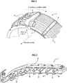
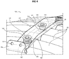
- the figure 3 and 4 illustrate a non-limiting example of a cooling system 100 for a casing 10 of a turbomachine according to one possible embodiment of the invention.
- the cooling system 100 is mounted around the casing 10 of a low pressure turbine.
- the cooling system 100 comprises several cooling tubes 120 mounted around the casing 10.
- the casing 10 extends around an axial direction of the turbomachine, and the cooling tubes 120 extend transversely to this axial direction, and are distributed along the circumference of the housing 10.
- the cooling system 100 also includes holding devices 101 of the cooling tubes 120 for positioning and maintaining the cooling tubes 120 around the housing 10.
- the cooling system 100 in the example shown is an LPTACC cooling device.
- the cooling tubes 120 and the holding device 101 constitute the cooling system 100 of the casing 10 of the low pressure turbine.
- Such a system can also be applied to an LPTC cooling device, or to any other turbomachine crankcase cooling system.
- the two cooling tubes 120 have orifices not visible on the figure 3 and 4 .
- the supply boxes supply relatively cool air with respect to the housing 10 to the cooling tubes 120, which send the air thus available to the outer face 11 of the housing 10 through the orifices (not visible in the figure).
- power boxes are distributed along the circumference of the cooling device.
- each zone of the cooling tubes 120 is supplied with air by a nearby supply box, which makes it possible to have an air flow sent via the orifices of the cooling tubes 120 sufficient whatever the considered zone of the tubes. cooling 120.
- the holding device 101 notably comprises a fixing support 104, here taking the form of a fixing plate, having a main part 105, a first end 106, and a second end (not shown).
- the fixing support 104 is secured to the casing 10 radially externally with respect to the casing 10.
- the ends 106 of the fixing support 104 may have fixing means such as holes 107 accommodating bolts or rivets, in order to allow fixing of the fixing support 104 integrally with the casing, possibly by means of intermediate structures. It is possible for the holes 107 to have an oblong shape, with a greater dimension in one direction (typically in the axial direction), in order to allow free expansion of the casing 10 with respect to the fixing support 104 in this direction.
- the holding device 101 comprises several holding elements 160 for the cooling tube 120.
- Each holding element 160 allows the attachment of at least one cooling tube 120.
- the holding element 160 is for example a holding support or a preformed retaining plate.
- the holding element 160 extends around a part of the circumference of a cooling tube 120, typically in the shape of a half-ring, and leaves free another part of the circumference of the cooling tube 120 intended to face the casing 10 of the turbomachine.
- the holding element 160 partially covers the periphery of the cooling tubes 120 and only a radially outer part of the cooling tubes 120, in particular the periphery of the cooling tubes 120 facing the mounting bracket 104. It is at this level that the holding element 160 is secured to the cooling tube 120, for example by brazing.
- the holding element can thus have a central part 161 that is generally planar and two portions 162, 163 in the shape of half-rings intended to match and to cover, at least partially, the annular shape of two adjacent cooling tubes 120 .
- the cooling tubes 120 are secured to the holding element 160 for example by brazing.
- the holding element 160 advantageously makes it possible to secure the cooling tubes at the level of a radially outer part of the cooling tubes, that is to say on the fixing support 104 side, in particular so as to avoid the presence of a part or an additional element between the cooling tube 120 and the casing 10, and so as to be able to bring the cooling tubes 120 closer to the casing 10 for the optimization of the cooling of the latter.
- the holding element 160 makes it possible to secure two cooling tubes 120 by means of the same and single holding element 160.
- two tubes are held and positioned cooling tubes 120 axially adjacent by making only one opening 108 in the mounting bracket 104.
- the mounting bracket 104 will have fewer openings 108 and less hanging zone than a mounting bracket according to the state of the art.
- it is also envisaged to produce a retaining element making it possible to individually secure a cooling tube so as to improve the precision of adjustment of the radial position of the cooling tubes 120 with respect to the casing 10.
- the holding device 101 also comprises a connection assembly 140 between the holding element 101 and the fixing support 104, the function of which is to provide the mechanical connection between the holding element 101 and the fixing support 104.
- the retaining element 101 must support at least one cooling tube 120 radially above the casing 10 leaving a clearance J between a cooling tube 120 and the outer surface 11 of the casing 10, and must therefore to do this be supported by mounting bracket 104.
- the connecting assembly 140 extends on either side of the mounting bracket 104, through the opening 108, which defines with respect to the mounting bracket 104 an outer part 141 of the connecting assembly 140, radially external to the fixing support 104, and an internal part 142 of the connection assembly, radially internal to the fixing support 104, on the side of the casing 10 of the turbomachine.
- the link assembly 140 includes a link piece 150 extending through the opening 108 of the mounting bracket 104, from the outer part 141 to the inner part 142 of the link assembly 140.
- the inner part 142 is integral with the retaining element 160.
- the connecting piece 150 can be a screw comprising a threaded body, and the internal part 142 can comprise a tapped receiving element 144 in which the threaded body of the the screw constituting the connecting element 150.
- the connecting piece 150 can pass through a hole in the holding element 160 and thus extend from one side radially inside the holding element 160, i.e. say in the direction of the housing 10.
- the receiving element 144 can then be arranged on the side radially internal to the holding element 160, so as to hold the holding element 160.
- the receiving element 144 can typically be a nut screwed onto one end of the screw 150, bearing against the radial face internal element of the holding element 160.
- the internal part 142 of the connecting piece is placed between two axially adjacent cooling tubes 120 .
- one end of the connecting piece 150 extends from the side radially internal to the retaining element 160 between the two axially adjacent cooling tubes 120 secured to the retaining element 160.
- the hole in the retaining element 160 which is crossed by the connecting piece is then provided in the central part 161 which joins the two portions 162, 163 in the form of half-rings.
- the link assembly 140 includes a sleeve 145 extending into the outer portion of the link assembly.
- the sleeve 145 has in its center a passage in which the connecting piece 150 extends.
- the sleeve 145 has a circular section.
- the sleeve 145 forms an abutment in the radially internal direction for the connecting piece 150.
- the connecting piece 150 has at its radially outer end a head 151 defined by an enlarged section, and the sleeve 145 has a shoulder 146 forming a stop in the radially internal direction for the head 151 of the connecting piece.
- the sleeve 145 comprises a first part having a wide section allowing the passage of the connecting piece 150, including its head 151, and preferably also allowing the passage of a tool for installing the connecting piece. 150, such as for example a tightening key engaged with the head 151.
- This first part is extended radially inwards by a second part having a narrow section, allowing the passage of one end of the connecting piece 150 but prohibiting the passage of the head 151, the transition between the first part and the second part of the sleeve 145 forming the shoulder 146.
- the second part of the sleeve 145 passes through the opening 108, thus protecting the connecting part 150.
- the second part of the sleeve 145 can then come into contact with the retaining part 160 on its radially outer face.
- the connecting piece 150 When fitting the connecting assembly 140, it is therefore sufficient to introduce the connecting piece 150 into the socket until the head 151 is in abutment against the shoulder 146. In the case where the connecting piece is a screw, this abutment can thus mark the screwing limit by naturally limiting it. It is therefore a very simple assembly requiring no adjustment. It is also possible to apply a predetermined tightening torque, for example the same for all the parts, which is not an adjustment torque. Alternatively, it would be possible to provide that the sleeve 145 and the connecting piece 150 form a single piece. Preferably, however, the sleeve 145 and the connecting piece 150 are separate.
- the connecting assembly 140 comprises in its outer part 141 an elastic return element biased in compression towards the fixing support 104 by the connecting part 150.
- the elastic return element preferably takes the form of a spring 170, as depicted on the figure 3 and 4 .
- the spring 170 is preferably disposed around the sleeve 145.
- the sleeve 145 forms an abutment in the radially outer direction for the spring 170.
- the sleeve has a flange 147 projecting in a direction opposite to the center of the sleeve 145 through which the connecting piece 150 passes, and the spring 170 is arranged between this flange 147 and the fixing support 104.
- this flange 147 extending from the outer end of the sleeve 145.
- the spring 170 is compressed in the direction of the mounting bracket 104 by the connecting piece 150.
- the action of the spring 170 makes it possible to guarantee that is exerted on the mounting bracket 104 a pressure allowing the plating of the connection assembly 140 on this fixing support 104, while authorizing a movement between the connection assembly 140 and this fixing support 104.
- the constant plating even during the movement makes it possible to guarantee the maintenance a game J between a cooling tube 120 and the housing 10, which can therefore be considered minimal.
- opening 108 in the fixing support 104 has a section greater than the section of the part of the connection assembly 140 passing through this opening 108, such that linkage assembly 140 is movable relative to mounting bracket 104, allowing free circumferential and/or radial expansion of cooling tubes 120 relative to mounting bracket 104.
- opening 108 has an oblong or oval cross-section, that is, with a larger dimension in one direction than in other directions.
- the opening of the fixing support 104 has in the circumferential direction of the turbomachine a dimension at least 1.5 times greater than its dimension in a direction (eg typically in the axial direction) perpendicular to the circumferential direction of the turbomachinery.
- This opening 108 thus allows movements of the sleeve 145 which passes through it in a plane orthogonal to the axis of the opening 108 and therefore also movements of the holding element 160 which is secured to the sleeve 145 by the part connecting 150. These movements allow the differential expansion of the cooling tubes 120 relative to the housing 10 during operation.
- the holding device may comprise an external support element 155 in the external part of the connection assembly 140, placed against the external face of the fixing support 104, on which the spring 170 presses.
- 155 is for example a metal washer.
- the external support element 155 is not integral with the sleeve 145.
- the external support element is not fixed to the fixing support 104, and therefore allows by its sliding on the surface of the fixing support 104 , the movement of the connection assembly 140 relative to the mounting bracket 104.
- An internal support element 156 may be present in the internal part 142 of the connection assembly, placed against the internal face of the fixing support 104 and separating the holding element 160 and said internal face of the fixing support 104.
- the internal support element 156 comprises an orifice facing the opening 108 of the fixing support 104.
- the internal support element 156 can for example be a metal washer.
- the internal support element 156 is not fixed to the fixing support 104, and therefore allows, by its sliding on the internal surface of the fixing support 104, the movement of the assembly 140 with respect to the mounting bracket 104.
- the internal support element 156 makes it possible to prevent the wear of the holding element 160 against the internal surface of the mounting bracket 104. It also makes it possible to guarantee a spacing of a determined distance between the retaining element 160 and the fixing support 104, avoiding providing a margin of tolerance for the clearance J between the cooling tubes 120 and the outer face 11 of the casing 10.
- the external support element 155 and the internal support element 156 can be used as possible adjustment variables (by their respective thicknesses or by their mere presence or absence) to obtain the desired clearance J. They can thus be used to rectify the shapes of other elements of the cooling system 100 which would impact the clearance J.
- the thickness of the external support element 155 and/or the internal support element 156 can be adapted to any variations in the distance between the mounting bracket 104 and the outer face 11 of the casing 10, in order to compensate for them. These elements can also be used as adjustment wedges during assembly if necessary.
- the holding elements 160 cooling tubes 120 are fixed to the cooling tubes 120, for example by brazing.
- various elements can be pre-assembled on the fixing support 104 before mounting the latter on the casing 10. It is for example possible to arrange the external support elements 155 therein with the orifices facing the opening 108, then to set up the springs 170 on these external support elements 155.
- the sleeves 145 are then introduced into the openings 108 so that the springs are compressed by the flanges 147 of the sleeves 145.
- the connecting pieces 150 are then put in place in the sockets 145, and come into engagement with the clamping element 142 of the internal part of the connecting assembly 140. The tightening of the connecting pieces 150 makes the socket 145 integral with the holding element 160.
- the connecting piece 150 is a screw
- the head 151 comes into abutment against the shoulder 146 of the sleeve 145.
- the sleeve 145 is then driven in the radially internal direction, through the opening 108, until it comes in abutment against the holding element 160. It is then no longer possible to tighten the connecting piece 150.
- the cooling system 100 consisting of the holding device 101 and the cooling tubes 120 can then be put in place on the casing 10, for example by using fixing means such as holes 107 present at the ends 106 of the fixing support 104.
- the installation of the retaining device 101 therefore does not require any particular adjustment to ensure an appropriate clearance J (in the radial direction of the turbine) between a cooling tube 120 and the outer face 11 of the casing 10.
- the clearance J is determined by the dimensions of the constituent elements of the holding device 101.
- the assembly of the holding device 101 is therefore greatly simplified. It suffices, for example, to screw the connecting piece 150 until it locks.
- the absence of the retaining element 160 between the cooling tube 120 and the casing 10 also means that a less thickness is to be taken into account for the dimensioning of the cooling system 100, facilitating this dimensioning and making it more precise, again making it possible to provide a minimum clearance J.
Landscapes
- Engineering & Computer Science (AREA)
- General Engineering & Computer Science (AREA)
- Mechanical Engineering (AREA)
- Chemical & Material Sciences (AREA)
- Combustion & Propulsion (AREA)
- Physics & Mathematics (AREA)
- Fluid Mechanics (AREA)
- Turbine Rotor Nozzle Sealing (AREA)
- Clamps And Clips (AREA)
- Structures Of Non-Positive Displacement Pumps (AREA)
Description
- La présente invention se rapporte au domaine des turbomachines, notamment pour aéronef, et concerne plus particulièrement un dispositif de maintien d'au moins un tube de refroidissement d'un système de refroidissement de carter de turbomachine.
- Pour assurer le refroidissement de certains carters, et notamment de carter de turbine basse pression, on prévoit un dispositif de refroidissement qui comprend un ensemble de tubes de refroidissement, également appelés rampes de refroidissement, percés de trous et disposés à l'extérieur du carter, le plus souvent en entourant ledit carter, de telle sorte que de l'air, aspiré en amont de la turbomachine par rapport à la direction d'écoulement des gaz dans la turbomachine, est envoyé vers la face externe du carter. Le système de refroidissement peut comprendre en outre plusieurs boitiers, disposés autour du carter pour alimenter en air les tubes de refroidissement.
- On connait des systèmes de refroidissement de type LPTCC ("Low Pressure Turbine Clearance Control" en langue anglaise, pour le contrôle des jeux pour turbine basse pression). Le système LPTCC peut être commandé par le FADEC (acronyme anglais de Full Authority Digital Engine Control, qui désigne un régulateur numérique de moteur à pleine autorité pour moteur d'aéronef) ; on parle alors de contrôle actif, le système étant alors désigné par l'acronyme LPTACC. Lorsqu'il n'est pas contrôlé par le FADEC, on parle de contrôle passif pour le système LPTCC. Sa fonction principale est de réguler le jeu rotor/stator entre les pièces de la turbine basse pression en modulant le débit d'air prélevé du flux secondaire pour le refroidissement du carter de turbine basse pression.
- Les tubes de refroidissement des systèmes LPTCC ou LPTACC, sont par exemple maintenus en position autour du carter par les boitiers d'alimentation et par des supports de fixation, solidaires du carter. Les supports de fixation peuvent être des tôles de fixation, généralement des tôles planes radialement sous lesquelles viennent se fixer des colliers de fixation, également appelés colliers à douche. Les colliers de fixation entourent les tubes de refroidissement et garantissent leur positionnement autour du carter.
- A cet effet, la
figure 1 montre une vue en perspective d'un système de refroidissement 1 pour carter de turbine basse pression d'une turbomachine selon l'état de la technique. Lesfigures 1 et 2 montrent un carter 2 de turbomachine, un système de refroidissement 1 pour le refroidissement du carter 2 comportant une pluralité de tubes de refroidissement 3, un boîtier d'alimentation 4 alimentant en air la pluralité de tubes de refroidissement, une pluralité de supports de fixation 5 pour le maintien en position des tubes de refroidissement 3 autour du carter 2. - La
figure 2 montre une vue partielle en coupe du système de refroidissement 1 pour carter de turbomachine selon l'état de la technique. Lafigure 2 montre plus particulièrement un support de fixation sous lequel vient se fixer une pluralité de colliers 6, chaque collier 6 entourant un tube de refroidissement 3. Un certain jeu (dans le sens radial de la turbine) est ménagé entre les colliers de fixation ou les tubes de refroidissement et l'enveloppe externe du carter notamment pour éviter tout contact des pièces (colliers de fixation, tubes de refroidissement, carter) qui pourrait occasionner des dommages. - Toutefois, le jeu entre les tubes de refroidissement et l'enveloppe externe du carter doit être le plus restreint possible pour positionner les tubes de refroidissement au plus près de l'enveloppe du carter et ainsi favoriser son refroidissement.
- En pratique, les contraintes technologiques, techniques, comme notamment les tolérances des pièces, les phénomènes vibratoires en fonctionnement, les dilatations des pièces en fonctionnement, imposent d'éloigner les tubes de refroidissement pour éviter tout contact entre les colliers de fixation (ou les tubes de refroidissement) qui pourrait endommager les pièces en contact, et notamment l'enveloppe externe du carter.
- La difficulté technique actuelle est de trouver un bon compromis de positionnement radial des tubes de refroidissement permettant d'éviter le contact des pièces tout en rendant le système de refroidissement le plus efficace possible grâce à un entrefer le plus petit possible entre les tubes de refroidissement et le carter. En effet, un jeu minimal est difficile à garantir et à maîtriser car le carter et les tubes de refroidissement sont des pièces de grand diamètre et les différentes pièces intermédiaires intervenant dans le maintien des tubes provoquent une accumulation des tolérances qui augmentent par conséquent le jeu minimal admissible.
- II a été notamment présenté différentes solutions permettant de mieux répondre à certaines contraintes. La demande de brevet français publiée sous le numéro
FR3021700 A1 - Le brevet
US689603 8 décrit un ensemble de ventilation, destinée à refroidir un anneau de stator d'une turbomachine, finit sur des rampes de soufflage de gaz composées de demi-coquilles symétriques jointes par soudage à leurs bordures opposées, et unies par des distributeurs composés pour l'essentiel de bobines cylindriques jouant le rôle d'entretoises placées entre les rampes et soudées à elles. Enfin, les moyens de maintien souple comprenant des règles permettent de compléter l'assemblage des rampes à l'anneau. - Toutefois, dans certaines situations et dans certaines configurations de turbomachine, les solutions connues ne sont pas complètement satisfaisantes et les contraintes d'efficacité de refroidissement imposent de réduire les jeux. Dans ces situations, des contacts entre les colliers de fixation et l'enveloppe de carter peuvent apparaître.
- Une autre solution consiste à prévoir un moyen de réglage configuré pour permettre de régler la position relative d'un élément de maintien d'un tube de refroidissement par rapport au support de fixation. Toutefois, une telle solution requiert un réglage fin, long et fastidieux lors du montage de chaque élément de maintien.
- La présente invention a pour but de remédier aux inconvénients de l'état de la technique en proposant un dispositif de maintien qui soit facile à monter, ne nécessite pas de réglage, et qui permet de maintenir un entrefer qui soit minimal tout en évitant des contacts entre les tubes de refroidissement et le carter de turbomachine, malgré les éventuelles dilatations des éléments de la turbomachine pouvant survenir en fonctionnement.
- A cet effet, l'invention a pour objet un dispositif de maintien d'au moins un tube de refroidissement d'un système de refroidissement de carter de turbomachine, le carter s'étendant autour d'une direction axiale de la turbomachine, le dispositif de maintien comportant un support de fixation adapté pour être solidarisé au carter de façon radialement externe par rapport au carter, un élément de maintien configuré pour maintenir le tube de refroidissement, et un ensemble de liaison disposé entre l'élément de maintien et le support de fixation, remarquable en ce que l'ensemble de liaison s'étend de part et d'autre du support de fixation, définissant par rapport au support de fixation une partie externe de l'ensemble de liaison radialement extérieure au support de fixation et une partie interne de l'ensemble de liaison, radialement intérieure au support de fixation, du côté du carter, l'ensemble de liaison comprenant une pièce de liaison s'étendant à travers une ouverture du support de fixation depuis la partie externe jusqu'à la partie interne, la partie interne radialement intérieure au support de fixation étant solidaire de l'élément de maintien tandis que la partie externe comprend un élément de rappel élastique sollicité en compression en direction du support de fixation par la pièce de liaison, dans lequel l'élément de maintien est configuré pour maintenir deux tubes de refroidissement axialement adjacents, et la partie interne de l'ensemble de liaison est disposée entre deux tubes de refroidissement axialement adjacents.
- Le dispositif est avantageusement complété par les caractéristiques suivantes, prises seules ou en une quelconque de leur combinaison techniquement possible :
- l'ouverture du support de fixation présente une section supérieure à la section de la partie de l'ensemble de liaison traversant cette ouverture, de sorte à autoriser un déplacement entre l'ensemble de liaison et le support, l'ouverture du support de fixation présentant une forme oblongue, l'ouverture du support de fixation présentant dans la direction circonférentielle une dimension au moins 1,5 fois supérieure à sa dimension dans la direction axiale ;
- le dispositif comprend une douille s'étendant dans la partie externe de l'ensemble de liaison, la douille formant butée dans la direction radialement interne pour la pièce de liaison, et formant butée dans la direction radialement externe pour l'élément de rappel élastique, dans lequel dans lequel la pièce de liaison présente à son extrémité radialement externe une tête définie par une section élargie, et la douille présente un épaulement formant butée dans la direction radialement interne pour la tête de la pièce de liaison, et dans lequel la douille présente une collerette et l'élément de rappel élastique est disposé entre cette collerette et le support de fixation ;
- la pièce de liaison est une vis comprenant un corps fileté, et la partie interne comprend un élément d'accueil taraudé disposé du côté radialement interne à l'élément de maintien, et dans lequel est vissé le corps fileté de la vis ;
- le dispositif comprend un élément externe d'appui dans la partie externe de l'ensemble de liaison, disposé contre la face externe du support de fixation, sur lequel appuie l'élément de rappel élastique ;
- le dispositif comprend un élément interne d'appui dans la partie interne de l'ensemble de liaison, disposé contre la face interne du support de fixation et séparant l'élément de maintien et ladite face interne du support de fixation ;
- l'élément de maintien vient recouvrir partiellement le pourtour des tubes de refroidissement et s'étend autour d'une partie de la circonférence d'un tube de refroidissement selon une forme de demi-anneau ;
- l'élément de maintien s'étend autour d'une partie de la circonférence d'un tube de refroidissement et laisse libre une autre partie de la circonférence du tube de refroidissement destinée à faire face au carter ;
- l'élément de maintien présente une partie centrale globalement plane et deux portions en forme de demi-anneaux destinées à épouser et à recouvrir, au moins partiellement, la forme annulaire des deux tubes de refroidissement adjacents ;
- un trou de l'élément de maintien traversé par la pièce de liaison est ménagé dans la partie centrale qui joint les deux portions en forme de demi-anneaux.
- L'invention concerne également un système de refroidissement de carter de turbomachine, comportant :
- au moins un tube de refroidissement,
- un dispositif de maintien selon l'invention, l'élément de maintien du dispositif de maintien maintenant deux tubes de refroidissement axialement adjacents.
- L'invention concerne également une turbomachine pour aéronef comprenant un carter s'étendant autour d'une direction axiale de la turbomachine, et un système de refroidissement selon l'invention, le système de refroidissement comprenant un dispositif de maintien comportant un support de fixation solidarisé au carter de façon radialement externe par rapport au carter, au moins un tube de refroidissement étant disposé de façon radialement externe par rapport au carter entre le carter et le support de fixation du dispositif de maintien.
- L'invention sera mieux comprise, grâce à la description ci-après, qui se rapporte à un exemple de réalisation préféré, donné à titre d'exemple non limitatif et expliqué avec référence aux dessins schématiques annexés, dans lesquels :
- la
figure 1 , déjà discutée, illustre une vue en perspective d'un système de refroidissement pour carter de turbine basse pression d'une turbomachine selon l'état de la technique, - la
figure. 2 , déjà discutée, illustre une vue en coupe d'un exemple de système de refroidissement pour carter de turbomachine de l'état de la technique, - la
figure 3 illustre une vue en coupe partielle d'un exemple de système de refroidissement pour carter de turbomachine selon un mode de réalisation possible de l'invention, - la
figure 4 illustre une vue en perspective d'un exemple de système de refroidissement pour carter de turbomachine selon un mode de réalisation possible de l'invention. - Les
figures 3 et4 illustrent un exemple non limitatif de système de refroidissement 100 pour un carter 10 de turbomachine selon un mode de réalisation possible de l'invention. Typiquement, et comme dans cet exemple, le système de refroidissement 100 est monté autour du carter 10 d'une turbine basse pression. - Le système de refroidissement 100 comprend plusieurs tubes de refroidissement 120 montés autour du carter 10. Le carter 10 s'étend autour d'une direction axiale de la turbomachine, et les tubes de refroidissement 120 s'étendent transversalement à cette direction axiale, et sont distribués le long de la circonférence du carter 10. Le système de refroidissement 100 comprend également des dispositifs de maintien 101 des tubes de refroidissement 120 pour le positionnement et le maintien des tubes de refroidissement 120 autour du carter 10.
- Le système de refroidissement 100 dans l'exemple représenté est un dispositif de refroidissement LPTACC. Avec typiquement des boîtiers d'alimentation, non représentés sur les
figures 3 et4 mais similaires au boîtier d'alimentation 4 de lafigure. 1 , les tubes de refroidissement 120 et le dispositif de maintien 101 constituent le système de refroidissement 100 du carter 10 de turbine basse pression. Un tel système peut également s'appliquer à un dispositif de refroidissement LPTC, ou à tout autre système de refroidissement de carter de turbomachine. - Classiquement, les deux tubes de refroidissement 120 présentent des orifices non visibles sur les
figures 3 et4 . En fonctionnement, les boîtiers d'alimentation alimentent en air relativement frais par rapport au carter 10 les tubes de refroidissement 120, qui envoient vers la face extérieure 11 du carter 10 l'air ainsi disponible au travers des orifices (non visibles sur la figure). Typiquement, les boîtiers d'alimentation sont distribués le long de la circonférence du dispositif de refroidissement. Ainsi, chaque zone des tubes de refroidissement 120 est alimentée en air par un boîtier d'alimentation proche, ce qui permet d'avoir un débit d'air envoyé via les orifices des tubes de refroidissement 120 suffisant quelle que soit la zone considérée des tubes de refroidissement 120. - Le dispositif de maintien 101 comprend notamment un support de fixation 104, prenant ici la forme d'une tôle de fixation, présentant une partie principale 105, une première extrémité 106, et une seconde extrémité (non représentée). Le support de fixation 104 est solidarisé au carter 10 de façon radialement externe par rapport au carter 10. A cet effet, les extrémités 106 du support de fixation 104 peuvent présenter des moyens de fixations tels que des trous 107 accueillant des boulons ou des rivets, afin de permettre la fixation du support de fixation 104 solidairement au carter, éventuellement par l'intermédiaire de structures intermédiaires. Il est possible que les trous 107 présentent une forme oblongue, avec une dimension supérieure dans une direction (typiquement dans la direction axiale), afin de permettre une libre dilatation du carter 10 par rapport au support de fixation 104 dans cette direction.
- Le dispositif de maintien 101 comprend plusieurs éléments de maintien 160 de tube de refroidissement 120. Chaque élément de maintien 160 permet l'accroche d'au moins un tube de refroidissement 120. L'élément de maintien 160 est par exemple un support de maintien ou une plaque de maintien préformée.
- Avantageusement, l'élément de maintien 160 s'étend autour d'une partie de la circonférence d'un tube de refroidissement 120, typiquement en forme de demi-anneau, et laisse libre une autre partie de la circonférence du tube de refroidissement 120 destinée à faire face au carter 10 de turbomachine. L'élément de maintien 160 vient recouvrir partiellement le pourtour des tubes de refroidissement 120 et uniquement une partie radialement externe des tubes de refroidissement 120, notamment le pourtour des tubes de refroidissement 120 en regard du support de fixation 104. C'est à ce niveau que l'élément de maintien 160 est rendu solidaire du tube de refroidissement 120, par exemple par brasage.
- L'élément de maintien peut ainsi présenter une partie centrale 161 globalement plane et deux portions 162, 163 en forme de demi-anneaux destinées à épouser et à recouvrir, au moins partiellement, la forme annulaire de deux tubes de refroidissement 120 adjacents. Les tubes de refroidissement 120 sont solidarisés sur l'élément de maintien 160 par exemple par brasage. L'élément de maintien 160 permet avantageusement de solidariser les tubes de refroidissement au niveau d'une partie radialement externe des tubes de refroidissement, c'est-à-dire côté support de fixation 104, notamment de manière à éviter la présence d'une pièce ou d'un élément supplémentaire entre le tube de refroidissement 120 et le carter 10, et de manière à pouvoir rapprocher davantage les tubes de refroidissement 120 du carter 10 pour l'optimisation du refroidissement de celui-ci.
- Avantageusement, l'élément de maintien 160, tel que représenté, permet de solidariser deux tubes de refroidissement 120 au moyen d'un même et unique élément de maintien 160. Dans ce mode de réalisation, on réalise un maintien et un positionnement de deux tubes de refroidissement 120 axialement adjacents en réalisant uniquement une ouverture 108 dans le support de fixation 104. Ainsi, pour une turbomachine donnée avec un nombre de tube de refroidissement donné, le support de fixation 104 selon l'invention présentera moins d'ouverture 108 et moins de zone d'accroché qu'un support de fixation selon l'état de la technique. Toutefois, il est également envisagé de réaliser un élément de maintien permettant de solidariser individuellement un tube de refroidissement de manière à améliorer la précision de réglage de la position radiale des tubes de refroidissement 120 par rapport au carter 10.
- Le dispositif de maintien 101 comprend également un ensemble de liaison 140 entre l'élément de maintien 101 et le support de fixation 104, qui a pour fonction de réaliser la liaison mécanique entre l'élément de maintien 101 et le support de fixation 104. En effet, l'élément de maintien 101 doit supporter au moins un tube de refroidissement 120 radialement au-dessus du carter 10 en laissant un jeu J entre un tube de refroidissement 120 et la surface externe 11 du carter 10, et doit donc pour ce faire être supporté par le support de fixation 104.
- L'ensemble de liaison 140 s'étend de part et d'autre du support de fixation 104, à travers l'ouverture 108, ce qui définit par rapport au support de fixation 104 une partie externe 141 de l'ensemble de liaison 140, radialement extérieure au support de fixation 104, et une partie interne 142 de l'ensemble de liaison, radialement intérieur au support de fixation 104, du côté du carter 10 de la turbomachine.
- L'ensemble de liaison 140 comprend une pièce de liaison 150 s'étendant à travers l'ouverture 108 du support de fixation 104, depuis la partie externe 141 jusqu'à la partie interne 142 de l'ensemble de liaison 140. La partie interne 142 est solidaire de l'élément de maintien 160. En particulier, la pièce de liaison 150 peut être une vis comprenant un corps fileté, et la partie interne 142 peut comprendre un élément d'accueil 144 taraudé dans lequel est vissé le corps fileté de la vis constituant l'élément de liaison 150. La pièce de liaison 150 peut traverser un trou de l'élément de maintien 160 et ainsi s'étendre d'un côté radialement interne à l'élément de maintien 160, c'est-à-dire en direction du carter 10. L'élément d'accueil 144 peut alors être disposé du côté radialement interne à l'élément de maintien 160, de sorte à maintenir l'élément de maintien 160. L'élément d'accueil 144 peut typiquement être un écrou vissé sur une extrémité de la vis 150, venant en appui sur la face radialement interne de l'élément de maintien 160.
- De préférence, la partie interne 142 de la pièce de liaison est disposée entre deux tubes de refroidissement 120 axialement adjacents. Ainsi, une extrémité de la pièce de liaison 150 s'étend du côté radialement interne à l'élément de maintien 160 entre les deux tubes de refroidissement 120 axialement adjacents solidaires de l'élément de maintien 160. Le trou de l'élément de maintien 160 qui est traversé par la pièce de liaison est alors ménagé dans la partie centrale 161 qui joint les deux portions 162, 163 en forme de demi-anneaux.
- L'ensemble de liaison 140 comprend une douille 145 s'étendant dans la partie externe de l'ensemble de liaison. La douille 145 présente en son centre un passage dans lequel s'étend la pièce de liaison 150. De préférence, la douille 145 présente une section circulaire. La douille 145 forme une butée dans la direction radialement interne pour la pièce de liaison 150. A cet effet, la pièce de liaison 150 présente à son extrémité radialement externe une tête 151 définie par une section élargie, et la douille 145 présente un épaulement 146 formant butée dans la direction radialement interne pour la tête 151 de la pièce de liaison.
- Plus précisément, la douille 145 comporte une première partie présentant une section large autorisant le passage de la pièce de liaison 150, y compris sa tête 151, et de préférence autorisant également le passage d'un outil de mise en place de la pièce de liaison 150, comme par exemple une clé de serrage en prise avec la tête 151. Cette première partie est prolongée radialement vers l'intérieur par une seconde partie présentant une section étroite, autorisant le passage d'une extrémité de la pièce de liaison 150 mais interdisant le passage de la tête 151, la transition entre la première partie et la deuxième partie de la douille 145 formant l'épaulement 146. De préférence, et comme illustré, la seconde partie de la douille 145 traverse l'ouverture 108, protégeant ainsi la pièce de liaison 150. La seconde partie de la douille 145 peut alors venir au contact de la pièce de maintien 160 sur sa face radialement extérieure.
- Lors de la mise en place de l'ensemble de liaison 140, il suffit donc d'introduire la pièce de liaison 150 dans la douille jusqu'à ce que la tête 151 soit en butée contre l'épaulement 146. Dans le cas où la pièce de liaison est une vis, cette butée peut ainsi marquer la limite de vissage en limitant naturellement celui-ci. Il s'agit donc d'un montage très simple ne requérant aucun réglage. Il est également possible d'appliquer un couple de serrage prédéterminé, par exemple le même pour toutes les pièces, qui ne soit pas un couple de réglage. Alternativement, il serait possible de prévoir que la douille 145 et la pièce de liaison 150 forme une seule pièce. De préférence toutefois, la douille 145 et la pièce de liaison 150 sont distinctes.
- L'ensemble de liaison 140 comprend dans sa partie externe 141 un élément de rappel élastique sollicité en compression en direction du support de fixation 104 par la pièce de liaison 150. L'élément de rappel élastique prend préférentiellement la forme d'un ressort 170, tel que représenté sur les
figures 3 et4 . Le ressort 170 est de préférence disposé autour de la douille 145. La douille 145 forme butée dans la direction radialement externe pour le ressort 170. Pour ce faire, et la douille présente une collerette 147 faisant saillie dans une direction opposée au centre de la douille 145 par lequel passe la pièce de liaison 150, et le ressort 170 est disposé entre cette collerette 147 et le support de fixation 104. De préférence, comme visible sur lafigure 4 , cette collerette 147 s'étendant depuis l'extrémité externe de la douille 145. - C'est par l'intermédiaire de la douille 145 que le ressort 170 est comprimé en direction du support de fixation 104 par la pièce de liaison 150. L'action du ressort 170 permet de garantir que s'exerce sur le support de fixation 104 une pression permettant le placage de l'ensemble de liaison 140 sur ce support de fixation 104, tout en autorisant un déplacement entre l'ensemble de liaison 140 et ce support de fixation 104. Le placage constant même lors du déplacement permet de garantir le maintien d'un jeu J entre un tube de refroidissement 120 et le carter 10, qui peut dès lors être envisagé minimal.
- Ce déplacement de l'ensemble de liaison 140 est en outre rendu possible par le fait que l'ouverture 108 dans le support de fixation 104 présente une section supérieure à la section de la partie de l'ensemble de liaison 140 traversant cette ouverture 108, de sorte que l'ensemble de liaison 140 est mobile par rapport au support de fixation 104, ce qui permet la libre dilatation circonférentielle et/ou radiale des tubes de refroidissement 120 par rapport au support de fixation 104. De préférence, l'ouverture 108 présente une section de forme oblongue ou ovale, c'est-à-dire avec une dimension plus grande dans une direction que dans d'autres directions. Par exemple, l'ouverture du support de fixation 104 présente dans la direction circonférentielle de la turbomachine une dimension au moins 1,5 fois supérieure à sa dimension dans une direction (e.g. typiquement dans la direction axiale) perpendiculaire à la direction circonférentielle de la turbomachine.
- Cette ouverture 108 autorise ainsi des déplacements de la douille 145 qui la traverse dans un plan orthogonal à l'axe de l'ouverture 108 et donc également des déplacements de l'élément de maintien 160 qui est rendu solidaire de la douille 145 par la pièce de liaison 150. Ces déplacements autorisent les dilatations différentielles des tubes de refroidissement 120 par rapport au carter 10 lors du fonctionnement.
- Le dispositif de maintien peut comprendre un élément externe d'appui 155 dans la partie externe de l'ensemble de liaison 140, disposé contre la face externe du support de fixation 104, sur lequel appuie le ressort 170. L'élément externe d'appui 155 est par exemple une rondelle métallique. L'élément externe d'appui 155 n'est pas solidaire de la douille 145. L'élément externe d'appui n'est pas fixé au support de fixation 104, et autorise donc par son glissement sur la surface du support de fixation 104, le déplacement de l'ensemble de liaison 140 par rapport au support de fixation 104.
- Un élément interne d'appui 156 peut être présent dans la partie interne 142 de l'ensemble de liaison, disposé contre la face interne du support de fixation 104 et séparant l'élément de maintien 160 et ladite face interne du support de fixation 104. L'élément interne d'appui 156 comprend un orifice faisant face à l'ouverture 108 du support de fixation 104. L'élément interne d'appui 156 peut par exemple être une rondelle métallique. Comme l'élément externe d'appui 155, l'élément interne d'appui 156 n'est pas fixé au support de fixation 104, et autorise donc, par son glissement sur la surface interne du support de fixation 104, le déplacement de l'ensemble de liaison 140 par rapport au support de fixation 104. L'élément interne d'appui 156 permet d'éviter l'usure de l'élément de maintien 160 contre la surface interne du support de fixation 104. Il permet également de garantir un écartement d'une distance déterminée entre l'élément de maintien 160 et le support de fixation 104, évitant de prévoir une marge de tolérance pour le jeu J entre les tubes de refroidissement 120 et la face extérieure 11 du carter 10.
- L'élément externe d'appui 155 et l'élément interne d'appui 156 peuvent être utilisées comme variables d'ajustement éventuelles (par leurs épaisseurs respectives ou par leur simple présence ou absence) pour obtenir le jeu J désiré. On peut ainsi les utiliser pour rectifier les formes d'autres éléments du système de refroidissement 100 qui impacteraient le jeu J. Par exemple, l'épaisseur de l'élément externe d'appui 155 et/ou l'élément interne d'appui 156 peut être adaptée à d'éventuelles variations de la distance entre le support de fixation 104 et la face extérieure 11 du carter 10, afin de les compenser. Ces éléments peuvent également être utilisés comme cale de réglage au montage si besoin.
- Lors de la mise en place du système de refroidissement 100, les éléments de maintien 160 des tubes de refroidissement 120 sont fixés aux tubes de refroidissement 120, par exemple par brasage. Avantageusement, différents éléments peuvent être préassemblés sur le support de fixation 104 avant le montage de celui-ci sur le carter 10. Il est par exemple possible d'y disposer les éléments externes d'appui 155 avec les orifices en face de l'ouverture 108, puis de mettre en place les ressorts 170 sur ces éléments externes d'appui 155. Les douilles 145 sont ensuite introduites dans les ouvertures 108 de sorte que les ressorts soient compressés par les collerettes 147 des douilles 145. Les pièces de liaison 150 sont alors mises en place dans les douilles 145, et viennent en prise avec l'élément de serrage 142 de la partie interne de l'ensemble de liaison 140. Le serrage des pièces de liaison 150 rend la douille 145 solidaire de l'élément de maintien 160. Plus précisément, dans le cas typique où la pièce de liaison 150 est une vis, il suffit de visser la vis jusqu'à son blocage. Lors du serrage d'une pièce de liaison 150, la tête 151 vient en butée contre l'épaulement 146 de la douille 145. La douille 145 est alors entraînée dans la direction radialement interne, à travers l'ouverture 108, jusqu'à venir en butée contre l'élément de maintien 160. Il n'est alors plus possible de serrer la pièce de liaison 150. Le système de refroidissement 100 constitué par le dispositif de maintien 101 et les tubes de refroidissement 120 peut alors être mis en place sur le carter 10, par exemple en utilisant les moyens de fixation tels que des trous 107 présents aux extrémités 106 du support de fixation 104.
- La partie externe 141 et la partie interne 142 de l'ensemble de liaison 140 sont alors solidarisées par la pièce de liaison 150, et maintiennent l'élément de maintien 160 par rapport au support de fixation 104, et donc le jeu J entre un tube de refroidissement 120 et la face extérieure 11 du carter 10, tout en permettant un déplacement relatif entre:
- d'une part l'ensemble de liaison 140, l'élément de maintien 160, et le tube de refroidissement 120, et
- d'autre part le support de fixation 104 et le carter 10.
- La mise en place du dispositif de maintien 101 ne requiert donc pas de réglage particulier pour assurer un jeu J (dans le sens radial de la turbine) approprié entre un tube de refroidissement 120 et la face extérieure 11 du carter 10. Le jeu J est déterminé par les dimensions des éléments constitutifs du dispositif de maintien 101. Le montage du dispositif de maintien 101 est donc grandement simplifié. Il suffit par exemple de visser jusqu'à son blocage la pièce de liaison 150.
- De plus, il est alors possible de prévoir un jeu J minimal, puisque celui-ci est garanti par le dispositif de maintien 101, et qu'il n'est donc plus nécessaire de prévoir une marge de tolérance. Eventuellement, en choisissant les caractéristiques (notamment l'épaisseur) des éléments d'appui 155, 156 pour les utiliser en tant que cale de réglage (pour gérer les dérogations par exemple), il est possible de réduire encore les tolérances sur le J.
- En outre, l'élément de maintien 160 d'un tube de refroidissement 120 laissant libre la partie du tube de refroidissement 120 qui fait face au carter 10, le refroidissement du carter 10 est amélioré, d'autant plus qu'il est possible de rapprocher ainsi le tube de refroidissement du carter 120. L'absence de l'élément de maintien 160 entre le tube de refroidissement 120 et le carter 10 signifie également qu'une épaisseur en moins est à prendre en compte pour le dimensionnement du système de refroidissement 100, facilitant ce dimensionnement et le rendant plus précis, permettant là encore de prévoir un jeu J minimal.
Claims (12)
- Dispositif de maintien (101) d'au moins un tube de refroidissement (120) d'un système de refroidissement (100) de carter (10) de turbomachine, le dispositif de maintien (101) s'étendant autour d'un axe définissant une direction axiale et comportant un support de fixation (104) adapté pour être solidarisé au carter (10) en étant disposé de façon radialement externe par rapport au carter (10), un élément de maintien (160) configuré pour maintenir le tube de refroidissement (120), et un ensemble de liaison (140) qui relie l'élément de maintien (160) et le support de fixation (104),
caractérisé en ce que l'ensemble de liaison (140) s'étend de part et d'autre du support de fixation (104), définissant par rapport au support de fixation (104) une partie externe (141) de l'ensemble de liaison radialement extérieure au support de fixation (104) et une partie interne (142) de l'ensemble de liaison, radialement intérieure au support de fixation (104), du côté du carter (10), l'ensemble de liaison (140) comprenant une pièce de liaison (150) s'étendant à travers une ouverture (108) du support de fixation (104) depuis la partie externe (141) jusqu'à la partie interne (142), la partie interne (142) radialement intérieure au support de fixation (104) étant solidaire de l'élément de maintien (160) tandis que la partie externe (141) comprend un élément de rappel élastique (170) sollicité en compression en direction du support de fixation (104) par la pièce de liaison (150), dans lequel l'élément de maintien (160) est configuré pour maintenir deux tubes de refroidissement (120) axialement adjacents, et la partie interne (142) de l'ensemble de liaison est disposée entre deux tubes de refroidissement (120) axialement adjacents. - Dispositif de maintien selon la revendication 1, dans lequel l'ouverture (108) du support de fixation (104) présente une section supérieure à la section de la partie de l'ensemble de liaison (140) traversant cette ouverture (108), de sorte à autoriser un déplacement entre l'ensemble de liaison (140) et le support (104), l'ouverture (108) du support de fixation (104) présentant une forme oblongue, l'ouverture (108) du support de fixation (104) présentant dans la direction circonférentielle une dimension au moins 1,5 fois supérieure à sa dimension dans la direction axiale.
- Dispositif de maintien selon l'une des revendications 1 à 2, comprenant une douille (145) s'étendant dans la partie externe (141) de l'ensemble de liaison (160), la douille formant butée dans la direction radialement interne pour la pièce de liaison (150), et formant butée dans la direction radialement externe pour l'élément de rappel élastique (170), dans lequel dans lequel la pièce de liaison (150) présente à son extrémité radialement externe une tête (151) définie par une section élargie, et la douille (145) présente un épaulement (146) formant butée dans la direction radialement interne pour la tête de la pièce de liaison (150), et dans lequel la douille présente une collerette (147) et l'élément de rappel élastique (170) est disposé entre cette collerette (147) et le support de fixation (104).
- Dispositif de maintien selon l'une des revendications 1 à 3, dans lequel la pièce de liaison (150) est une vis comprenant un corps fileté, et la partie interne comprend un élément d'accueil (144) taraudé disposé du côté radialement interne à l'élément de maintien (160), et dans lequel est vissé le corps fileté de la vis.
- Dispositif de maintien selon l'une des revendications 1 à 4, comprenant un élément externe d'appui (155) dans la partie externe (141) de l'ensemble de liaison (140), disposé contre la face externe du support de fixation (104), sur lequel appuie l'élément de rappel élastique (170).
- Dispositif de maintien selon l'une des revendications 1 à 5, comprenant un élément interne d'appui (156) dans la partie interne (142) de l'ensemble de liaison (140), disposé contre la face interne du support de fixation (104) et séparant l'élément de maintien (160) et ladite face interne du support de fixation (104).
- Dispositif de maintien selon l'une des revendications 1 à 6, dans lequel l'élément de maintien (160) vient recouvrir partiellement le pourtour des tubes de refroidissement (120) et s'étend autour d'une partie de la circonférence d'un tube de refroidissement (120) selon une forme de demi-anneau.
- Dispositif de maintien selon l'une des revendications 1 à 7, dans lequel l'élément de maintien (160) s'étend autour d'une partie de la circonférence d'un tube de refroidissement et laisse libre une autre partie de la circonférence du tube de refroidissement destinée à faire face au carter (10).
- Dispositif de maintien selon l'une des revendications 1 à 8, dans lequel l'élément de maintien présente une partie centrale (161) globalement plane et deux portions (162, 163) en forme de demi-anneaux destinées à épouser et à recouvrir, au moins partiellement, la forme annulaire des deux tubes de refroidissement (120) adjacents.
- Dispositif de maintien selon la revendication 9, dans lequel un trou de l'élément de maintien (160) traversé par la pièce de liaison (150) est ménagé dans la partie centrale (161) qui joint les deux portions (162, 163) en forme de demi-anneaux.
- Système (100) de refroidissement de carter de turbomachine, comportant :- une pluralité de tubes de refroidissement (120),- un dispositif de maintien (101) selon l'une des revendications précédentes, l'élément de maintien (160) maintenant deux tubes de refroidissement axialement adjacents.
- Turbomachine pour aéronef comprenant un carter (10) s'étendant autour d'une direction axiale de la turbomachine, et un système de refroidissement (100) selon la revendication précédente, le support de fixation (104) étant solidarisé au carter (10) de façon radialement externe par rapport au carter (10), la pluralité de tubes de refroidissement (120) étant disposée de façon radialement externe par rapport au carter (10) entre le carter (10) et le support de fixation (104).
Applications Claiming Priority (1)
| Application Number | Priority Date | Filing Date | Title |
|---|---|---|---|
| FR1872452A FR3089560B1 (fr) | 2018-12-06 | 2018-12-06 | Dispositif de maintien d'un tube de refroidissement pour carter de turbomachine |
Publications (2)
| Publication Number | Publication Date |
|---|---|
| EP3663534A1 EP3663534A1 (fr) | 2020-06-10 |
| EP3663534B1 true EP3663534B1 (fr) | 2022-11-09 |
Family
ID=67383803
Family Applications (1)
| Application Number | Title | Priority Date | Filing Date |
|---|---|---|---|
| EP19212270.3A Active EP3663534B1 (fr) | 2018-12-06 | 2019-11-28 | Dispositif de maintien d'un tube de refroidissement pour carter de turbomachine |
Country Status (4)
| Country | Link |
|---|---|
| US (1) | US11555405B2 (fr) |
| EP (1) | EP3663534B1 (fr) |
| CN (1) | CN111287808B (fr) |
| FR (1) | FR3089560B1 (fr) |
Cited By (1)
| Publication number | Priority date | Publication date | Assignee | Title |
|---|---|---|---|---|
| WO2025088276A1 (fr) | 2023-10-26 | 2025-05-01 | Safran Aircraft Engines | Dispositif de refroidissement par jets d'air d'un carter de turbine et turbomachine comportant un tel dispositif |
Families Citing this family (2)
| Publication number | Priority date | Publication date | Assignee | Title |
|---|---|---|---|---|
| FR3127012B1 (fr) * | 2021-09-14 | 2024-11-08 | Safran Aircraft Engines | Douille pour boitier de distribution d’air de turbomachine |
| FR3137406A1 (fr) * | 2022-07-04 | 2024-01-05 | Safran Aircraft Engines | Carter de turbine de turboreacteur equipe de dispositifs mobiles de fixation de tubes de refroidissement |
Family Cites Families (13)
| Publication number | Priority date | Publication date | Assignee | Title |
|---|---|---|---|---|
| US5271588A (en) * | 1992-07-17 | 1993-12-21 | General Electric Company | Multi-piece tube clamp |
| FR2816352B1 (fr) * | 2000-11-09 | 2003-01-31 | Snecma Moteurs | Ensemble de ventilation d'un anneau de stator |
| US9341074B2 (en) * | 2012-07-25 | 2016-05-17 | General Electric Company | Active clearance control manifold system |
| FR2995022B1 (fr) * | 2012-09-04 | 2017-11-24 | Snecma | Dispositif de fixation d'un systeme de refroidissement pour carter de turboreacteur d'aeronef |
| FR3002590B1 (fr) * | 2013-02-26 | 2015-04-03 | Snecma | Dispositif de refroidissement pour carter de turboreacteur d'aeronef comportant un dispositif de maintien |
| US20150233496A1 (en) * | 2014-02-19 | 2015-08-20 | Entertainment Structural Products | Multi-Connection Truss Pick |
| FR3021700B1 (fr) * | 2014-05-27 | 2016-07-01 | Snecma | Dispositif de maintien d'un tube de refroidissement pour carter de turboreacteur |
| FR3040429B1 (fr) * | 2015-08-27 | 2019-06-07 | Safran Aircraft Engines | Dispositif de fixation des rampes de refroidissement par jets d'air du carter d'une turbine de turbomachine |
| FR3058460B1 (fr) * | 2016-11-08 | 2018-11-09 | Safran Aircraft Engines | Ensemble de raccordement pour le refroidissement d'une turbine de turbomachine |
| FR3073007B1 (fr) * | 2017-10-27 | 2019-09-27 | Safran Aircraft Engines | Dispositif de maintien d'un tube de refroidissement pour carter de turbomachine |
| FR3077097B1 (fr) * | 2018-01-22 | 2020-08-07 | Safran Aircraft Engines | Dispositif de refroidissement pour une turbine d'une turbomachine |
| FR3079560B1 (fr) * | 2018-04-03 | 2020-10-09 | Safran Aircraft Engines | Dispositif de refroidissement pour une turbine d'une turbomachine |
| FR3079874B1 (fr) * | 2018-04-09 | 2020-03-13 | Safran Aircraft Engines | Dispositif de refroidissement pour une turbine d'une turbomachine |
-
2018
- 2018-12-06 FR FR1872452A patent/FR3089560B1/fr not_active Expired - Fee Related
-
2019
- 2019-11-28 EP EP19212270.3A patent/EP3663534B1/fr active Active
- 2019-12-05 US US16/704,031 patent/US11555405B2/en active Active
- 2019-12-05 CN CN201911232089.3A patent/CN111287808B/zh active Active
Cited By (2)
| Publication number | Priority date | Publication date | Assignee | Title |
|---|---|---|---|---|
| WO2025088276A1 (fr) | 2023-10-26 | 2025-05-01 | Safran Aircraft Engines | Dispositif de refroidissement par jets d'air d'un carter de turbine et turbomachine comportant un tel dispositif |
| FR3154755A1 (fr) * | 2023-10-26 | 2025-05-02 | Safran Aircraft Engines | Dispositif de refroidissement par jets d’air d’un carter de turbine et turbomachine comportant un tel dispositif |
Also Published As
| Publication number | Publication date |
|---|---|
| FR3089560B1 (fr) | 2021-01-22 |
| FR3089560A1 (fr) | 2020-06-12 |
| US11555405B2 (en) | 2023-01-17 |
| CN111287808B (zh) | 2022-05-24 |
| EP3663534A1 (fr) | 2020-06-10 |
| CN111287808A (zh) | 2020-06-16 |
| US20200182058A1 (en) | 2020-06-11 |
Similar Documents
| Publication | Publication Date | Title |
|---|---|---|
| EP3663534B1 (fr) | Dispositif de maintien d'un tube de refroidissement pour carter de turbomachine | |
| EP3701128B1 (fr) | Dispositif de maintien d'un tube de refroidissement pour carter de turbomachine | |
| EP3230602B1 (fr) | Anneau de commande d'un étage d'aubes à calage variable pour une turbomachine | |
| EP3074611B1 (fr) | Dispositif pour le centrage et le guidage en rotation d'un arbre de turbomachine comprenant des moyens améliorés de rétention de bague extérieure de palier | |
| EP3775501B1 (fr) | Dispositif de refroidissement pour une turbine d'une turbomachine | |
| EP3775498B1 (fr) | Dispositif de refroidissement pour une turbine d'une turbomachine | |
| FR2949518A1 (fr) | Compresseur de turbomachine ayant des injecteurs d'air | |
| EP3084140B1 (fr) | Bras de guidage d'éléments de forme allongée, en particulier pour une turbomachine | |
| FR3077097A1 (fr) | Dispositif de refroidissement pour une turbine d'une turbomachine | |
| EP3204654A1 (fr) | Assemblage de deux pièces comprenant une coupelle de centrage amovible pour turbomachine d'aéronef | |
| EP3638891B1 (fr) | Gicleur a vis captive | |
| FR2884868A1 (fr) | Dispositif d'alimentation en carburant d'une chambre de combustion dans une turbomachine | |
| FR3026827A1 (fr) | Chambre de combustion de turbomachine | |
| EP2598803A2 (fr) | Systeme d'injection de carburant pour turbo-reacteur et procede d'assemblage d'un tel systeme d'injection | |
| FR2970755A1 (fr) | Dispositif de galet tendeur de courroie et procede d'assemblage associe | |
| EP4010563B1 (fr) | Dispositif de refroidissement par jets d'air d'un carter externe de turbomachine et turbomachine équipée d'un tel dispositif | |
| FR2942638A1 (fr) | Secteur angulaire de redresseur pour compresseur de turbomachine | |
| FR2988436A1 (fr) | Dispositif de guidage d'une bougie d'allumage | |
| FR3051014A1 (fr) | Ensemble pour turbomachine comprenant un distributeur, un element de structure de turbomachine, et un dispositif de fixation | |
| WO2018002480A1 (fr) | Ensemble de fixation d'un distributeur a un element de structure d'une turbomachine | |
| EP3384193B1 (fr) | Dispositif de limitation de desserrage d'un ecrou dans une turbomachine | |
| FR3119646A1 (fr) | Rotor de turbomachine | |
| FR3081533A1 (fr) | Dispositif de fixation et de maintien d'au moins un harnais electrique dans une turbomachine | |
| FR2944089A1 (fr) | Accrochage de chambre annulaire de combustion | |
| FR3105996A1 (fr) | Organe de verrouillage destiné à l’assemblage d’une première pièce et d’une seconde pièce d’une turbomachine |
Legal Events
| Date | Code | Title | Description |
|---|---|---|---|
| PUAI | Public reference made under article 153(3) epc to a published international application that has entered the european phase |
Free format text: ORIGINAL CODE: 0009012 |
|
| STAA | Information on the status of an ep patent application or granted ep patent |
Free format text: STATUS: REQUEST FOR EXAMINATION WAS MADE |
|
| 17P | Request for examination filed |
Effective date: 20191128 |
|
| AK | Designated contracting states |
Kind code of ref document: A1 Designated state(s): AL AT BE BG CH CY CZ DE DK EE ES FI FR GB GR HR HU IE IS IT LI LT LU LV MC MK MT NL NO PL PT RO RS SE SI SK SM TR |
|
| AX | Request for extension of the european patent |
Extension state: BA ME |
|
| GRAP | Despatch of communication of intention to grant a patent |
Free format text: ORIGINAL CODE: EPIDOSNIGR1 |
|
| STAA | Information on the status of an ep patent application or granted ep patent |
Free format text: STATUS: GRANT OF PATENT IS INTENDED |
|
| GRAS | Grant fee paid |
Free format text: ORIGINAL CODE: EPIDOSNIGR3 |
|
| INTG | Intention to grant announced |
Effective date: 20220906 |
|
| GRAA | (expected) grant |
Free format text: ORIGINAL CODE: 0009210 |
|
| STAA | Information on the status of an ep patent application or granted ep patent |
Free format text: STATUS: THE PATENT HAS BEEN GRANTED |
|
| AK | Designated contracting states |
Kind code of ref document: B1 Designated state(s): AL AT BE BG CH CY CZ DE DK EE ES FI FR GB GR HR HU IE IS IT LI LT LU LV MC MK MT NL NO PL PT RO RS SE SI SK SM TR |
|
| REG | Reference to a national code |
Ref country code: GB Ref legal event code: FG4D Free format text: NOT ENGLISH |
|
| REG | Reference to a national code |
Ref country code: CH Ref legal event code: EP Ref country code: AT Ref legal event code: REF Ref document number: 1530505 Country of ref document: AT Kind code of ref document: T Effective date: 20221115 |
|
| REG | Reference to a national code |
Ref country code: DE Ref legal event code: R096 Ref document number: 602019021655 Country of ref document: DE |
|
| REG | Reference to a national code |
Ref country code: IE Ref legal event code: FG4D Free format text: LANGUAGE OF EP DOCUMENT: FRENCH |
|
| REG | Reference to a national code |
Ref country code: LT Ref legal event code: MG9D |
|
| REG | Reference to a national code |
Ref country code: NL Ref legal event code: MP Effective date: 20221109 |
|
| REG | Reference to a national code |
Ref country code: AT Ref legal event code: MK05 Ref document number: 1530505 Country of ref document: AT Kind code of ref document: T Effective date: 20221109 |
|
| PG25 | Lapsed in a contracting state [announced via postgrant information from national office to epo] |
Ref country code: SE Free format text: LAPSE BECAUSE OF FAILURE TO SUBMIT A TRANSLATION OF THE DESCRIPTION OR TO PAY THE FEE WITHIN THE PRESCRIBED TIME-LIMIT Effective date: 20221109 Ref country code: PT Free format text: LAPSE BECAUSE OF FAILURE TO SUBMIT A TRANSLATION OF THE DESCRIPTION OR TO PAY THE FEE WITHIN THE PRESCRIBED TIME-LIMIT Effective date: 20230309 Ref country code: NO Free format text: LAPSE BECAUSE OF FAILURE TO SUBMIT A TRANSLATION OF THE DESCRIPTION OR TO PAY THE FEE WITHIN THE PRESCRIBED TIME-LIMIT Effective date: 20230209 Ref country code: LT Free format text: LAPSE BECAUSE OF FAILURE TO SUBMIT A TRANSLATION OF THE DESCRIPTION OR TO PAY THE FEE WITHIN THE PRESCRIBED TIME-LIMIT Effective date: 20221109 Ref country code: FI Free format text: LAPSE BECAUSE OF FAILURE TO SUBMIT A TRANSLATION OF THE DESCRIPTION OR TO PAY THE FEE WITHIN THE PRESCRIBED TIME-LIMIT Effective date: 20221109 Ref country code: ES Free format text: LAPSE BECAUSE OF FAILURE TO SUBMIT A TRANSLATION OF THE DESCRIPTION OR TO PAY THE FEE WITHIN THE PRESCRIBED TIME-LIMIT Effective date: 20221109 Ref country code: AT Free format text: LAPSE BECAUSE OF FAILURE TO SUBMIT A TRANSLATION OF THE DESCRIPTION OR TO PAY THE FEE WITHIN THE PRESCRIBED TIME-LIMIT Effective date: 20221109 |
|
| PG25 | Lapsed in a contracting state [announced via postgrant information from national office to epo] |
Ref country code: RS Free format text: LAPSE BECAUSE OF FAILURE TO SUBMIT A TRANSLATION OF THE DESCRIPTION OR TO PAY THE FEE WITHIN THE PRESCRIBED TIME-LIMIT Effective date: 20221109 Ref country code: PL Free format text: LAPSE BECAUSE OF FAILURE TO SUBMIT A TRANSLATION OF THE DESCRIPTION OR TO PAY THE FEE WITHIN THE PRESCRIBED TIME-LIMIT Effective date: 20221109 Ref country code: LV Free format text: LAPSE BECAUSE OF FAILURE TO SUBMIT A TRANSLATION OF THE DESCRIPTION OR TO PAY THE FEE WITHIN THE PRESCRIBED TIME-LIMIT Effective date: 20221109 Ref country code: IS Free format text: LAPSE BECAUSE OF FAILURE TO SUBMIT A TRANSLATION OF THE DESCRIPTION OR TO PAY THE FEE WITHIN THE PRESCRIBED TIME-LIMIT Effective date: 20230309 Ref country code: HR Free format text: LAPSE BECAUSE OF FAILURE TO SUBMIT A TRANSLATION OF THE DESCRIPTION OR TO PAY THE FEE WITHIN THE PRESCRIBED TIME-LIMIT Effective date: 20221109 Ref country code: GR Free format text: LAPSE BECAUSE OF FAILURE TO SUBMIT A TRANSLATION OF THE DESCRIPTION OR TO PAY THE FEE WITHIN THE PRESCRIBED TIME-LIMIT Effective date: 20230210 |
|
| PG25 | Lapsed in a contracting state [announced via postgrant information from national office to epo] |
Ref country code: NL Free format text: LAPSE BECAUSE OF FAILURE TO SUBMIT A TRANSLATION OF THE DESCRIPTION OR TO PAY THE FEE WITHIN THE PRESCRIBED TIME-LIMIT Effective date: 20221109 |
|
| REG | Reference to a national code |
Ref country code: CH Ref legal event code: PL |
|
| REG | Reference to a national code |
Ref country code: BE Ref legal event code: MM Effective date: 20221130 |
|
| PG25 | Lapsed in a contracting state [announced via postgrant information from national office to epo] |
Ref country code: SM Free format text: LAPSE BECAUSE OF FAILURE TO SUBMIT A TRANSLATION OF THE DESCRIPTION OR TO PAY THE FEE WITHIN THE PRESCRIBED TIME-LIMIT Effective date: 20221109 Ref country code: RO Free format text: LAPSE BECAUSE OF FAILURE TO SUBMIT A TRANSLATION OF THE DESCRIPTION OR TO PAY THE FEE WITHIN THE PRESCRIBED TIME-LIMIT Effective date: 20221109 Ref country code: LI Free format text: LAPSE BECAUSE OF NON-PAYMENT OF DUE FEES Effective date: 20221130 Ref country code: EE Free format text: LAPSE BECAUSE OF FAILURE TO SUBMIT A TRANSLATION OF THE DESCRIPTION OR TO PAY THE FEE WITHIN THE PRESCRIBED TIME-LIMIT Effective date: 20221109 Ref country code: DK Free format text: LAPSE BECAUSE OF FAILURE TO SUBMIT A TRANSLATION OF THE DESCRIPTION OR TO PAY THE FEE WITHIN THE PRESCRIBED TIME-LIMIT Effective date: 20221109 Ref country code: CZ Free format text: LAPSE BECAUSE OF FAILURE TO SUBMIT A TRANSLATION OF THE DESCRIPTION OR TO PAY THE FEE WITHIN THE PRESCRIBED TIME-LIMIT Effective date: 20221109 Ref country code: CH Free format text: LAPSE BECAUSE OF NON-PAYMENT OF DUE FEES Effective date: 20221130 |
|
| REG | Reference to a national code |
Ref country code: DE Ref legal event code: R097 Ref document number: 602019021655 Country of ref document: DE |
|
| PG25 | Lapsed in a contracting state [announced via postgrant information from national office to epo] |
Ref country code: SK Free format text: LAPSE BECAUSE OF FAILURE TO SUBMIT A TRANSLATION OF THE DESCRIPTION OR TO PAY THE FEE WITHIN THE PRESCRIBED TIME-LIMIT Effective date: 20221109 Ref country code: LU Free format text: LAPSE BECAUSE OF NON-PAYMENT OF DUE FEES Effective date: 20221128 Ref country code: AL Free format text: LAPSE BECAUSE OF FAILURE TO SUBMIT A TRANSLATION OF THE DESCRIPTION OR TO PAY THE FEE WITHIN THE PRESCRIBED TIME-LIMIT Effective date: 20221109 |
|
| PLBE | No opposition filed within time limit |
Free format text: ORIGINAL CODE: 0009261 |
|
| STAA | Information on the status of an ep patent application or granted ep patent |
Free format text: STATUS: NO OPPOSITION FILED WITHIN TIME LIMIT |
|
| 26N | No opposition filed |
Effective date: 20230810 |
|
| PG25 | Lapsed in a contracting state [announced via postgrant information from national office to epo] |
Ref country code: IE Free format text: LAPSE BECAUSE OF NON-PAYMENT OF DUE FEES Effective date: 20221128 |
|
| PG25 | Lapsed in a contracting state [announced via postgrant information from national office to epo] |
Ref country code: SI Free format text: LAPSE BECAUSE OF FAILURE TO SUBMIT A TRANSLATION OF THE DESCRIPTION OR TO PAY THE FEE WITHIN THE PRESCRIBED TIME-LIMIT Effective date: 20221109 Ref country code: BE Free format text: LAPSE BECAUSE OF NON-PAYMENT OF DUE FEES Effective date: 20221130 |
|
| PG25 | Lapsed in a contracting state [announced via postgrant information from national office to epo] |
Ref country code: HU Free format text: LAPSE BECAUSE OF FAILURE TO SUBMIT A TRANSLATION OF THE DESCRIPTION OR TO PAY THE FEE WITHIN THE PRESCRIBED TIME-LIMIT; INVALID AB INITIO Effective date: 20191128 |
|
| PG25 | Lapsed in a contracting state [announced via postgrant information from national office to epo] |
Ref country code: CY Free format text: LAPSE BECAUSE OF FAILURE TO SUBMIT A TRANSLATION OF THE DESCRIPTION OR TO PAY THE FEE WITHIN THE PRESCRIBED TIME-LIMIT Effective date: 20221109 |
|
| PG25 | Lapsed in a contracting state [announced via postgrant information from national office to epo] |
Ref country code: MK Free format text: LAPSE BECAUSE OF FAILURE TO SUBMIT A TRANSLATION OF THE DESCRIPTION OR TO PAY THE FEE WITHIN THE PRESCRIBED TIME-LIMIT Effective date: 20221109 Ref country code: IT Free format text: LAPSE BECAUSE OF FAILURE TO SUBMIT A TRANSLATION OF THE DESCRIPTION OR TO PAY THE FEE WITHIN THE PRESCRIBED TIME-LIMIT Effective date: 20221109 |
|
| PG25 | Lapsed in a contracting state [announced via postgrant information from national office to epo] |
Ref country code: MC Free format text: LAPSE BECAUSE OF FAILURE TO SUBMIT A TRANSLATION OF THE DESCRIPTION OR TO PAY THE FEE WITHIN THE PRESCRIBED TIME-LIMIT Effective date: 20221109 |
|
| PG25 | Lapsed in a contracting state [announced via postgrant information from national office to epo] |
Ref country code: MC Free format text: LAPSE BECAUSE OF FAILURE TO SUBMIT A TRANSLATION OF THE DESCRIPTION OR TO PAY THE FEE WITHIN THE PRESCRIBED TIME-LIMIT Effective date: 20221109 |
|
| PG25 | Lapsed in a contracting state [announced via postgrant information from national office to epo] |
Ref country code: BG Free format text: LAPSE BECAUSE OF FAILURE TO SUBMIT A TRANSLATION OF THE DESCRIPTION OR TO PAY THE FEE WITHIN THE PRESCRIBED TIME-LIMIT Effective date: 20221109 |
|
| PG25 | Lapsed in a contracting state [announced via postgrant information from national office to epo] |
Ref country code: MT Free format text: LAPSE BECAUSE OF FAILURE TO SUBMIT A TRANSLATION OF THE DESCRIPTION OR TO PAY THE FEE WITHIN THE PRESCRIBED TIME-LIMIT Effective date: 20221109 |
|
| PG25 | Lapsed in a contracting state [announced via postgrant information from national office to epo] |
Ref country code: TR Free format text: LAPSE BECAUSE OF FAILURE TO SUBMIT A TRANSLATION OF THE DESCRIPTION OR TO PAY THE FEE WITHIN THE PRESCRIBED TIME-LIMIT Effective date: 20221109 |
|
| PGFP | Annual fee paid to national office [announced via postgrant information from national office to epo] |
Ref country code: DE Payment date: 20251118 Year of fee payment: 7 |
|
| PGFP | Annual fee paid to national office [announced via postgrant information from national office to epo] |
Ref country code: GB Payment date: 20251125 Year of fee payment: 7 |
|
| PGFP | Annual fee paid to national office [announced via postgrant information from national office to epo] |
Ref country code: FR Payment date: 20251125 Year of fee payment: 7 |