EP3663477B1 - Ceiling system and building system comprising such ceiling system - Google Patents
Ceiling system and building system comprising such ceiling system Download PDFInfo
- Publication number
- EP3663477B1 EP3663477B1 EP18209786.5A EP18209786A EP3663477B1 EP 3663477 B1 EP3663477 B1 EP 3663477B1 EP 18209786 A EP18209786 A EP 18209786A EP 3663477 B1 EP3663477 B1 EP 3663477B1
- Authority
- EP
- European Patent Office
- Prior art keywords
- plenum
- ceiling
- partition wall
- space
- building system
- Prior art date
- Legal status (The legal status is an assumption and is not a legal conclusion. Google has not performed a legal analysis and makes no representation as to the accuracy of the status listed.)
- Active
Links
- 238000005192 partition Methods 0.000 claims description 101
- 238000009408 flooring Methods 0.000 claims description 70
- 238000000605 extraction Methods 0.000 claims description 5
- 229910052602 gypsum Inorganic materials 0.000 claims description 5
- 239000010440 gypsum Substances 0.000 claims description 5
- 239000000463 material Substances 0.000 claims description 4
- 239000011490 mineral wool Substances 0.000 claims description 4
- 210000002268 wool Anatomy 0.000 claims description 4
- 238000005286 illumination Methods 0.000 claims description 3
- 239000002184 metal Substances 0.000 claims description 3
- 229910052751 metal Inorganic materials 0.000 claims description 3
- 239000002245 particle Substances 0.000 claims description 3
- 239000002023 wood Substances 0.000 claims description 3
- 239000002557 mineral fiber Substances 0.000 claims 1
- 238000009423 ventilation Methods 0.000 description 9
- 239000002657 fibrous material Substances 0.000 description 4
- 239000000835 fiber Substances 0.000 description 3
- 230000006978 adaptation Effects 0.000 description 2
- 238000000034 method Methods 0.000 description 2
- 238000012986 modification Methods 0.000 description 2
- 230000004048 modification Effects 0.000 description 2
- 239000005030 aluminium foil Substances 0.000 description 1
- 230000015572 biosynthetic process Effects 0.000 description 1
- 230000001419 dependent effect Effects 0.000 description 1
- 239000011521 glass Substances 0.000 description 1
- 229910052500 inorganic mineral Inorganic materials 0.000 description 1
- 238000009434 installation Methods 0.000 description 1
- 239000011707 mineral Substances 0.000 description 1
- 230000000149 penetrating effect Effects 0.000 description 1
- 238000000638 solvent extraction Methods 0.000 description 1
- 239000004575 stone Substances 0.000 description 1
Images

Classifications
-
- E—FIXED CONSTRUCTIONS
- E04—BUILDING
- E04B—GENERAL BUILDING CONSTRUCTIONS; WALLS, e.g. PARTITIONS; ROOFS; FLOORS; CEILINGS; INSULATION OR OTHER PROTECTION OF BUILDINGS
- E04B9/00—Ceilings; Construction of ceilings, e.g. false ceilings; Ceiling construction with regard to insulation
- E04B9/02—Ceilings; Construction of ceilings, e.g. false ceilings; Ceiling construction with regard to insulation having means for ventilation or vapour discharge
-
- E—FIXED CONSTRUCTIONS
- E04—BUILDING
- E04B—GENERAL BUILDING CONSTRUCTIONS; WALLS, e.g. PARTITIONS; ROOFS; FLOORS; CEILINGS; INSULATION OR OTHER PROTECTION OF BUILDINGS
- E04B2/00—Walls, e.g. partitions, for buildings; Wall construction with regard to insulation; Connections specially adapted to walls
- E04B2/72—Non-load-bearing walls of elements of relatively thin form with respect to the thickness of the wall
-
- E—FIXED CONSTRUCTIONS
- E04—BUILDING
- E04B—GENERAL BUILDING CONSTRUCTIONS; WALLS, e.g. PARTITIONS; ROOFS; FLOORS; CEILINGS; INSULATION OR OTHER PROTECTION OF BUILDINGS
- E04B9/00—Ceilings; Construction of ceilings, e.g. false ceilings; Ceiling construction with regard to insulation
- E04B9/008—Ceilings; Construction of ceilings, e.g. false ceilings; Ceiling construction with regard to insulation with means for connecting partition walls or panels to the ceilings
-
- F—MECHANICAL ENGINEERING; LIGHTING; HEATING; WEAPONS; BLASTING
- F24—HEATING; RANGES; VENTILATING
- F24F—AIR-CONDITIONING; AIR-HUMIDIFICATION; VENTILATION; USE OF AIR CURRENTS FOR SCREENING
- F24F13/00—Details common to, or for air-conditioning, air-humidification, ventilation or use of air currents for screening
- F24F13/02—Ducting arrangements
- F24F13/0227—Ducting arrangements using parts of the building, e.g. air ducts inside the floor, walls or ceiling of a building
-
- F—MECHANICAL ENGINEERING; LIGHTING; HEATING; WEAPONS; BLASTING
- F24—HEATING; RANGES; VENTILATING
- F24F—AIR-CONDITIONING; AIR-HUMIDIFICATION; VENTILATION; USE OF AIR CURRENTS FOR SCREENING
- F24F13/00—Details common to, or for air-conditioning, air-humidification, ventilation or use of air currents for screening
- F24F13/02—Ducting arrangements
- F24F13/0272—Modules for easy installation or transport
-
- F—MECHANICAL ENGINEERING; LIGHTING; HEATING; WEAPONS; BLASTING
- F24—HEATING; RANGES; VENTILATING
- F24F—AIR-CONDITIONING; AIR-HUMIDIFICATION; VENTILATION; USE OF AIR CURRENTS FOR SCREENING
- F24F13/00—Details common to, or for air-conditioning, air-humidification, ventilation or use of air currents for screening
- F24F13/02—Ducting arrangements
- F24F13/06—Outlets for directing or distributing air into rooms or spaces, e.g. ceiling air diffuser
-
- E—FIXED CONSTRUCTIONS
- E04—BUILDING
- E04B—GENERAL BUILDING CONSTRUCTIONS; WALLS, e.g. PARTITIONS; ROOFS; FLOORS; CEILINGS; INSULATION OR OTHER PROTECTION OF BUILDINGS
- E04B9/00—Ceilings; Construction of ceilings, e.g. false ceilings; Ceiling construction with regard to insulation
- E04B9/006—Ceilings; Construction of ceilings, e.g. false ceilings; Ceiling construction with regard to insulation with means for hanging lighting fixtures or other appliances to the framework of the ceiling
Definitions
- the present invention relates to a building system and more specifically to such a building system comprising a ceiling system in a building space defined by a structural ceiling and a flooring.
- a building such as a commercial building may comprise one or more building spaces defined by a structural ceiling and a flooring of the building.
- a suspended ceiling may be arranged below the structural ceiling defining a flooring space between the suspended ceiling and the flooring.
- the flooring may be partitioned into a plurality of areas or rooms by means of partition walls.
- the building space may be provided with equipment for ventilation and lighting, and the equipment is arranged to provide desired conditions in each area or room of the flooring space.
- the equipment is often arranged in the plenum space defined between the structural ceiling and the suspended ceiling.
- the distribution of rooms or areas in the flooring space may be changed several times during the life time of the building, and each change of room layout often necessitates changes in the equipment for ventilation and lighting.
- each change of room layout often necessitates changes in the equipment for ventilation and lighting.
- a change in the room layout may be time consuming to execute and may also affect the daily operation in the entire flooring space while the refurbishing work is ongoing.
- the object of the present invention is to provide a building system providing an efficient infrastructure in a building.
- Another object is to provide such a building system enabling efficient room ventilation for a building space and which facilitates adaptations in an existing room layout.
- a building system comprising a building space defined by a structural ceiling and a flooring of a building, and a ceiling system, the ceiling system comprising an air permeable suspended ceiling arranged below the structural ceiling, wherein a plenum space is formed between the suspended ceiling and the structural ceiling and a flooring space is formed between the flooring and the suspended ceiling, and a plurality of partition wall sections, the plurality of partition wall sections being arranged in the plenum space, extending between the structural ceiling and the suspended ceiling and forming a plurality of plenum modules distributed across the plenum space.
- plenum modules comprising equipment in the form of a supply air device for each plenum module in combination with the provision of an air permeable suspended ceiling allows for controlled delivery of supply air to the part of the flooring space situated below the associated plenum module by means of diffuse ceiling ventilation.
- the plenum module forms a defined part of the plenum space, and the plenum module thus forms an enclosed pressure zone for the supply air.
- One or more plenum modules may be utilized when partitioning a room in the flooring space simply by aligning the partition walls defining the room with suitable partition wall sections of the one or more plenum modules. As described above, each plenum module forms an enclosed pressure zone for the supply air delivered to the plenum module, and thus the delivery of supply air to the room via diffuse ceiling ventilation may be uniform and controlled also in the case the room extends over two or more plenum modules.
- each partition wall of the plurality of partition walls is aligned with an associated partition wall section of the plurality of partition wall sections, a versatile building system is provided allowing for easy adaptation of the room layout in the flooring space.
- the equipment of at least one plenum module may further comprise an exhaust air device for extraction of exhaust air from the flooring space.
- an exhaust air device for extraction of air from the flooring space.
- extraction of air from a room extending across one or more plenum modules not having any exhaust air device may be accomplished by means of an exhaust air devices arranged in partition walls providing an air flow path to a room extending across one or more plenum modules comprising an exhaust air device.
- each plenum module may be associated with a sensor arrangement for collecting sensor data from a part of the flooring space situated below the associated plenum module, wherein a control unit may be arranged to receive the sensor data from the sensor arrangements for control of the equipment of each plenum module.
- the control unit may comprise a control box arranged in each plenum module arranged to receive the sensor data from the associated sensor arrangement.
- the control unit may further comprise steering boxes, wherein each steering box is arranged to receive the sensor data as input data from a group of control boxes.
- Each steering box may comprise a CPU arranged to control the equipment of the associated plenum modules based on the received input data.
- the plurality of plenum modules may comprise a plenum module group having a rectangular shape, enabling the design of a room layout comprising rooms of conventional rectangular shape.
- the partition wall section may be utilized for securing a partition wall aligned with the same.
- the partition wall may be indirectly secured in the partition wall section via the suspended ceiling.
- the partition wall may adjoin the lower edge surface and be directly secured in the partition wall section.
- Each plenum module 9 forms a closed space defined by the structural ceiling 2, the suspended ceiling 5 and the associated partition wall sections 6.
- the plenum module 9 to the right in the figure is also defined by a wall section of the building.
- the plurality of partition wall sections 6 may be separately formed from the structural ceiling 2, or may be integrally formed with the structural ceiling 2.
- the partition wall sections 6 are illustrated by dashed lines and define a plurality of plenum modules 9 distributed across the plenum space 7. More specifically, the plenum modules 9 are distributed in accordance with a plenum module layout forming a modularization layout of the flooring space 8.
- the plenum module layout forming the modularization layout corresponds to the extension of the partition wall sections 6 in combination with the wall sections 15 of the building. It is understood that some plenum modules also may be defined by other building elements, such as stairwells or elevator shafts, and that the plenum module layout in such cases also is affected by these building elements.
- One plenum module has an elongated rectangular shape corresponding to a corridor module of the modularization layout.
- the equipment further comprises a lighting device 16 for illumination of a part of the flooring space 8 situated below the associated plenum module 9.
- the lighting devices 16 of the plenum modules 9 comprised in the plenum module group having a rectangular shape and unitary size each comprises two light units 17, and the elongated rectangular plenum module 9 comprises nine light units 17.
- Each control box 22 is coupled to the sensor arrangement 18 of the associated plenum module 9 and is arranged to receive sensor data from the sensor arrangement 18 and to transfer the sensor data as input data to the associated steering box 21.
- a first room located in the lower left hand corner of the building space extends over four consecutive plenum modules 9.
- the sensor arrangements 18 of the plenum modules 9 have accordingly been adjusted in accordance with the size of the first room, and more specifically, three PIR-sensors and three CO 2 -sensors have been disconnected from the associated connections boxes 22 such that only one PIR-sensor 19 and one CO 2 -sensor 20 remain active for obtaining sensor data from the first room. Corresponding amendments have been made for the remaining rooms and areas.
- the ceiling system facilitates modifications in the room layout at a later stage. For instance, if were to be decided that the relatively large first room should be converted into two rooms, this may easily be accomplished by erecting an additional partition wall in the first room in accordance with the modularization layout and by adjusting the sensor arrangements such that a CO 2 -sensor and a PIR-sensor are provided for each room, and also by implementing the new sensor arrangement set up in the steering box coupled to the associated connection boxes.
- the partition wall sections 6 have been disclosed as having such an extension that the lower edge surface 10 of each partition wall section 6 extends beyond the front surface 11 of the suspended ceiling 5.
- Such a design provides a clear indication of the modularization layout which is visible from the flooring space 8 and which makes it easy to align partition walls 14 with the associated partition wall sections 6.
Description
- The present invention relates to a building system and more specifically to such a building system comprising a ceiling system in a building space defined by a structural ceiling and a flooring.
- A building such as a commercial building may comprise one or more building spaces defined by a structural ceiling and a flooring of the building. A suspended ceiling may be arranged below the structural ceiling defining a flooring space between the suspended ceiling and the flooring. The flooring may be partitioned into a plurality of areas or rooms by means of partition walls.
- The building space may be provided with equipment for ventilation and lighting, and the equipment is arranged to provide desired conditions in each area or room of the flooring space. The equipment is often arranged in the plenum space defined between the structural ceiling and the suspended ceiling.
- The distribution of rooms or areas in the flooring space, i.e. the room layout, may be changed several times during the life time of the building, and each change of room layout often necessitates changes in the equipment for ventilation and lighting. Thus, even a little change in the room layout relating to only a minor part of the flooring space may result in a change with regard to the equipment for ventilation and lighting affecting the entire flooring space. As a consequence, a change in the room layout may be time consuming to execute and may also affect the daily operation in the entire flooring space while the refurbishing work is ongoing.
-
- In view of that stated above, the object of the present invention is to provide a building system providing an efficient infrastructure in a building.
- Another object is to provide such a building system enabling efficient room ventilation for a building space and which facilitates adaptations in an existing room layout.
- To achieve at least one of the above objects and also other objects that will be evident from the following description, a building system having the features defined in claim 1 is provided according to the present invention. Preferred embodiments of the building system will be evident from the dependent claims.
- More specifically, there is provided according to the present invention a building system comprising a building space defined by a structural ceiling and a flooring of a building, and a ceiling system, the ceiling system comprising an air permeable suspended ceiling arranged below the structural ceiling, wherein a plenum space is formed between the suspended ceiling and the structural ceiling and a flooring space is formed between the flooring and the suspended ceiling, and a plurality of partition wall sections, the plurality of partition wall sections being arranged in the plenum space, extending between the structural ceiling and the suspended ceiling and forming a plurality of plenum modules distributed across the plenum space. The building system further comprising a plurality of partition walls arranged in the flooring space extending from the flooring to the suspended ceiling, wherein each partition wall of the plurality of partition walls is aligned with an associated partition wall section of the plurality of partition wall sections, wherein each of the plurality of plenum modules forms a closed space defined by the structural ceiling, the suspended ceiling and the associated partition wall sections. Each of the plurality of plenum modules comprises equipment, the equipment of each plenum module comprising a supply air device for delivery of supply air to the associated plenum module for pressurization thereof such that the supply air delivered to the plenum module is supplied to the flooring space through the air permeable suspended ceiling.
- The provision of a plurality of plenum modules comprising equipment in the form of a supply air device for each plenum module in combination with the provision of an air permeable suspended ceiling allows for controlled delivery of supply air to the part of the flooring space situated below the associated plenum module by means of diffuse ceiling ventilation. The plenum module forms a defined part of the plenum space, and the plenum module thus forms an enclosed pressure zone for the supply air. The supply air delivered to the plenum module by means of the supply air device is then allowed to diffuse or penetrate through the air permeable suspended ceiling and enter the flooring space below over a large area, resulting in a flow of the supply air with no concentrated jet region, thereby providing high ventilation capacity while avoiding the creation of thermal discomfort such as draught even if the supply air temperature is different from the room temperature and the air flow is high. Thus, the ceiling system allows for a controlled ventilation of the flooring space providing good air quality and thermal comfort.
- One or more plenum modules may be utilized when partitioning a room in the flooring space simply by aligning the partition walls defining the room with suitable partition wall sections of the one or more plenum modules. As described above, each plenum module forms an enclosed pressure zone for the supply air delivered to the plenum module, and thus the delivery of supply air to the room via diffuse ceiling ventilation may be uniform and controlled also in the case the room extends over two or more plenum modules.
- The ceiling system facilitates changes in the room layout of the flooring space since additional partition walls may be erected at a later stage and aligned with unused partition wall sections in the plenum space such that the modular feature of the ceiling system is maintained. Correspondingly, partition walls may be removed at a later stage. A change in room layout does thus not require major changes of the ceiling system, and may thus be carried out swiftly. Also, the modular feature of the ceiling system ensures that a change in room layout only concerning a minor part of the flooring space does not affect the daily operation in the entire flooring space while the refurbishing work is ongoing.
- By having a plurality of partition walls arranged in the flooring space extending from the flooring to the ceiling system, wherein each partition wall of the plurality of partition walls is aligned with an associated partition wall section of the plurality of partition wall sections, a versatile building system is provided allowing for easy adaptation of the room layout in the flooring space.
- By each of the plurality of plenum modules forming a closed space defined by the structural ceiling, the suspended ceiling and the associated partition wall sections, pressurization and the formation of a pressure zone inside each plenum module is facilitated, enabling a controlled diffuse ceiling ventilation through the suspended ceiling. The partition wall sections of the plenum modules may be non-air permeable, thereby preventing air leakage from one plenum module to an adjacent plenum module
- According to an embodiment, the plurality of plenum modules may be distributed across the plenum space in accordance with a plenum module layout forming a modularization layout of the flooring space. Hereby, the process of designing the room layout of the flooring space is further facilitated. The modularization layout formed by the plenum module layout indicates the possible positions for erecting partition walls in the flooring space aligned with the partition wall sections in the plenum space such that the advantages of the plenum modules may be utilized. This means that the ceiling system controls the design of the room layout in the flooring space. A later change in room layout is also facilitated as long as the change is done in accordance with the modularization layout provided by the ceiling system. Thus, one bigger room extending over several plenum modules may be converted into several smaller rooms by erecting partition walls inside the bigger room aligned with previous unused partition wall sections associated with the plenum modules. Correspondingly, two or more adjacent rooms may be converted into one big room simply by removing partition walls.
- According to another embodiment of the building system, the equipment of at least one plenum module may further comprise an exhaust air device for extraction of exhaust air from the flooring space. For the case when only some of the plenum modules comprise exhaust air devices, extraction of air from a room extending across one or more plenum modules not having any exhaust air device, may be accomplished by means of an exhaust air devices arranged in partition walls providing an air flow path to a room extending across one or more plenum modules comprising an exhaust air device.
- According to yet another embodiment of the building system, the equipment of each plenum module may further comprise a lighting device for illumination of a part of the flooring space situated below the associated plenum module. By the provision of a lighting device for each plenum module, changes in room layout may easily be carried out without necessitating rewiring of the lighting devices. Each lighting device may comprise one or more light units and may be mounted in or suspended from the suspended ceiling.
- According to yet another embodiment of the building system, each plenum module may be associated with a sensor arrangement for collecting sensor data from a part of the flooring space situated below the associated plenum module, wherein a control unit may be arranged to receive the sensor data from the sensor arrangements for control of the equipment of each plenum module. For instance, the control unit may comprise a control box arranged in each plenum module arranged to receive the sensor data from the associated sensor arrangement. The control unit may further comprise steering boxes, wherein each steering box is arranged to receive the sensor data as input data from a group of control boxes. Each steering box may comprise a CPU arranged to control the equipment of the associated plenum modules based on the received input data.
- The sensor arrangement associated with each plenum module may comprise PIR-sensor, light sensor, temperature sensor, CO2-sensor, gas sensor, particle sensor and/or humidity sensor. Other types of sensors for obtaining relevant sensor data are also conceivable.
- The plurality of plenum modules may comprise a plenum module group having a rectangular shape, enabling the design of a room layout comprising rooms of conventional rectangular shape.
- The plurality of plenum modules may comprise a plenum module group having a unitary size, enabling the design of a room layout comprising rooms having equal size.
- According to yet another embodiment of the building system, at least one partition wall section of the plurality of partition wall section may have a lower edge surface abutting a rear surface of the suspended ceiling. By designing the partition wall sections such that the lower edge surface abuts the rear surface of the suspended ceiling, it is possible to provide an unbroken suspended ceiling extending over the flooring space which may facilitate installation of the suspended ceiling.
- According to yet another embodiment of the building system, at least one partition wall section of the plurality of partition wall section may a lower edge surface extending beyond a front surface of the suspended ceiling. Hereby, the partition wall section provides an indication visible from the flooring space for aligning a partition wall with the partition wall section.
- The partition wall section may be utilized for securing a partition wall aligned with the same. In case the lower edge surface of the partition wall sections abuts the rear surface of the suspended ceiling, the partition wall may be indirectly secured in the partition wall section via the suspended ceiling. On the other hand, in case the lower edge surface extends beyond the front surface of the suspended ceiling, the partition wall may adjoin the lower edge surface and be directly secured in the partition wall section.
- The plurality of partition wall sections may be separately formed from the structural ceiling or may be integrally formed with the structural ceiling.
- According to yet another embodiment of the building system, the suspended ceiling may comprise ceiling tiles made of fiber material, such as mineral wool or wood wool. Hereby, an air permeable suspended ceiling is provided where supply air delivered to the plenum modules may penetrate through the porous structure of the ceiling tiles in a controlled manner and with a controlled pressure drop, and possible also through gaps and other openings in the suspended ceiling, to the flooring space below the plenum modules.
- According to yet another embodiment of the ceiling system, the suspended ceiling may comprise ceiling tiles in the form of perforated panels such as perforated gypsum boards or perforated metal panels. Hereby, an air permeable suspended ceiling is provided where supply air delivered to the plenum modules may penetrate through perforations of the ceiling tiles in a controlled manner and with a controlled pressure drop, and possible also through gaps and other openings in the suspended ceiling, to the flooring space below the plenum modules.
- Generally, all terms used in the claims are to be interpreted according to their ordinary meaning in the technical field, unless explicitly defined otherwise herein. All references to "a/an/the [element, device, component, means, step, etc]" are to be interpreted openly as referring to at least one instance of said element, device, component, means, step, etc., unless explicitly stated otherwise. The steps of any method disclosed herein do not have to be performed in the exact order disclosed, unless explicitly stated.
- The above, as well as additional objects, features and advantages of the present invention, will be better understood through the following illustrative and non-limiting detailed description of preferred embodiments of the present invention, with reference to the appended drawings, where the same reference numerals will be used for similar elements, wherein:
-
Fig.1 is a schematic side view of a building system comprising a building space and a ceiling system. -
Fig. 2 is a schematic top view of a building system with a ceiling system comprising plenum modules distributed according to a plenum module layout forming a modularization layout for a flooring space. -
Fig. 3 is a schematic top view of a building system with a ceiling system according toFig. 2 and partition walls. -
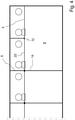
Fig. 4 is a schematic side view comprising an alternative embodiment of the building system. - The present invention will now be described more fully hereinafter with reference to the accompanying drawings, in which currently preferred embodiments of the invention are shown. This invention may, however, be embodied in many different forms and should not be construed as limited to the embodiments set forth herein; rather, these embodiments are provided for thoroughness and completeness, and fully convey the scope of the invention to the skilled person.
-
Fig. 1 illustrates a building system 1 comprising a building space defined by astructural ceiling 2 and aflooring 3 of a building; and a ceiling system 4 arranged the in building space. - The building, such as a commercial building, may comprise one or more floors, and each floor may comprise one or more building spaces.
- The ceiling system 4 comprises an air permeable suspended
ceiling 5 and a plurality ofpartition wall sections 6. - The suspended
ceiling 5 is arranged below thestructural ceiling 2, wherein a plenum space 7 is formed between the suspendedceiling 5 and thestructural ceiling 2 and aflooring space 8 is formed between theflooring 3 and the suspendedceiling 5. - The air permeable suspended
ceiling 5 may comprise ceiling tiles made of fiber material or ceiling tiles made of perforated panel material. The fiber material may be wood wool or mineral wool, such as glass or stone wool. The fiber material may be compressed. The perforated panel material may be perforated gypsum boards or perforated metal panels. - The suspended ceiling system 4 may comprise a grid of profiles (not shown) suspended in the
structural ceiling 2 and supporting the suspendedceiling 5. - The plurality of
partition wall sections 6 is arranged in the plenum space 7 extend between thestructural ceiling 2 and the suspendedceiling 5 such that a plurality ofplenum modules 9 is formed distributed across the plenum space 7. Onesuch plenum module 9 is indicated by dashed lines. - Each
plenum module 9 forms a closed space defined by thestructural ceiling 2, the suspendedceiling 5 and the associatedpartition wall sections 6. Theplenum module 9 to the right in the figure is also defined by a wall section of the building. - The
partition wall section 6 may have alower edge surface 10 below afront surface 11 of the suspendedceiling 5, and in the shown embodiment, allpartition wall sections 5 have such alower edge surface 10 extending beyond thefront surface 11 of the suspendedceiling 5. - The
partition wall sections 6 may be non-air permeable. - The plurality of
partition wall sections 6 may be separately formed from thestructural ceiling 2, or may be integrally formed with thestructural ceiling 2. - As a non-limiting example, a
partition wall section 6 may comprise a frame formed by joists and studs covered by panel elements such as gypsum boards. - As another non-limiting example, a partition wall section may be formed by a fiber element having some flexibility, such as a mineral wool element, supporting a non-air permeable covering, such as aluminium foil. Such a partition wall section made of a fiber element may be wedged into place between the structural ceiling and the suspended ceiling.
- Each
plenum module 9 comprises equipment. More specifically, the equipment of each plenum module comprises asupply air device 12 for delivery of supply air to the associatedplenum module 9. In the shown embodiment of the ceiling system, the equipment of each plenum module also comprises anexhaust air device 13 for extraction of exhaust air from a part of the flooring space situated below the associatedplenum module 9. - Since each
plenum module 9 is pressurized and may form a closed space defined by thestructural ceiling 2, the suspendedceiling 5 and the associatedpartition wall sections 6, supply air delivered to theplenum module 9 will thus in turn be delivered to the part of theflooring space 8 situated below the associatedplenum module 9 in a controlled manner via the air permeable suspended ceiling 5.The building system further comprisespartition walls 14 arranged in theflooring space 8 extending from theflooring 3 to the ceiling system 4, wherein eachpartition wall 14 is aligned with an associatedpartition wall section 6 of the plurality ofpartition wall sections 6. - A partition wall aligned with a partition wall section may be secured in the same. When the lower edge surface of the partition wall section extends beyond the front surface of the suspended ceiling, the partition wall may adjoin the lower edge surface and be directly secured in the partition wall section.
- In
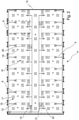
Fig. 2 , to which reference now is also made, the ceiling system 4 arranged in a building space is illustrated from above. - The
partition wall sections 6 are illustrated by dashed lines and define a plurality ofplenum modules 9 distributed across the plenum space 7. More specifically, theplenum modules 9 are distributed in accordance with a plenum module layout forming a modularization layout of theflooring space 8. The plenum module layout forming the modularization layout corresponds to the extension of thepartition wall sections 6 in combination with thewall sections 15 of the building. It is understood that some plenum modules also may be defined by other building elements, such as stairwells or elevator shafts, and that the plenum module layout in such cases also is affected by these building elements. - The plenum module layout may be determined by a modularization property of the building, and the in the shown embodiment the plenum module layout is based on the window layout in the facade of the building.
- The plenum module layout may form a modularization layout for room modules and aisle or corridor modules situated below the associated
plenum modules 9. - In the shown embodiment, a group of
plenum modules 9 has a rectangular shape and a unitary size corresponding to room modules in the modularization layout of theflooring space 8. - One plenum module has an elongated rectangular shape corresponding to a corridor module of the modularization layout.
- The modularization layout of the
flooring space 8 thus indicates the possible positioning ofpartition walls 14 in the flooring space such that thepartition walls 14 are aligned withpartition wall sections 6 arranged in the plenum space 7. Thus, when determining the actual room layout of theflooring space 8, the modularization layout will determine the possible distribution of rooms, areas and aisles. - In the shown embodiment, each
plenum module 9 comprises equipment. - The equipment comprises a
supply air device 12 for delivery of supply air to the associatedplenum module 9. As described above, the supply air will be delivered to the part of theflooring space 8 situated below the associatedplenum module 9 via the air permeable suspendedceiling 5. Thesupply air devices 12 may comprise VAV (variable air volume) dampers and silencers. - The suspended
ceiling 5 may comprise ceiling tiles made of compressed mineral fibre material, and in such a case, the supply air may be delivered to theflooring space 8 by penetrating or diffusing through the porous structure of the ceiling tiles. Alternatively, the suspendedceiling 5 may comprise ceiling tiles made of perforated boards, such as gypsum boards, and in such a case the supply air will be delivered to theflooring space 8 via the perforations in the ceiling tiles. - The equipment of each plenum module further comprises an
exhaust air device 13 for extraction of exhaust air from a part of theflooring space 8 situated below the associatedplenum module 9. - It is understood that each plenum module need not comprise an exhaust air device. For instance, when designing a room layout based on the modularization layout, some rooms may be provided with exhaust devices installed in the partition walls, and the plenum module/modules of such a room does thus not need an exhaust air device arranged in the associated plenum module/modules.
- The equipment further comprises a
lighting device 16 for illumination of a part of theflooring space 8 situated below the associatedplenum module 9. In the shown embodiment, thelighting devices 16 of theplenum modules 9 comprised in the plenum module group having a rectangular shape and unitary size each comprises twolight units 17, and the elongatedrectangular plenum module 9 comprises ninelight units 17. - The plenum module may further be associated with a
sensor arrangement 18 for collecting sensor data from a part of the flooring space 7 situated below the associatedplenum module 9. The sensor arrangement may comprise PIR-sensor, light sensor, temperature sensor, CO2-sensor (20), gas sensor, particle sensor and/or humidity sensor.. It is understood that the sensor arrangement may comprise other types of sensors for obtaining relevant sensor data for control of the equipment. The sensors may be arranged in a part of the suspendedceiling 5 defining the associatedplenum module 9, or may be arranged in the part of theflooring space 8 situated below the associatedplenum module 9. - In the shown embodiment, the
plenum modules 9 of unitary size are each associated with asensor arrangement 18 comprising PIR-sensor 19 and CO2-sensor 20. - The ceiling system 4 may comprise a control unit arranged to receive the input data from the
sensor arrangements 18 for control of the equipment of eachplenum module 9. - In the shown embodiment, the control unit comprises three steering
boxes 21 as well as acontrol box 22 associated with eachplenum module 9 comprised in the plenum module group having a rectangular shape and unitary size. - Each
steering box 21 comprises a CPU, power supply and other necessary components, and is connected to thecontrol boxes 22 of a group of plenum modules. - Each
control box 22 is coupled to thesensor arrangement 18 of the associatedplenum module 9 and is arranged to receive sensor data from thesensor arrangement 18 and to transfer the sensor data as input data to the associatedsteering box 21. - Thus, the
air supply devices 12 may be controlled by the steering boxes 24 based on input data obtained from associatedcontrol boxes 22 comprising sensor data from for instance temperature sensors, PIR-sensors and/or CO2-sensors. Further, thelighting devices 16 may be controlled by thesteering boxes 21 based on input data obtained from associatedcontrol boxes 22 comprising sensor data from for instance PIR-sensors. -
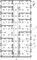
Fig. 3 illustrates a building space comprising the ceiling system, wherein the modularization layout formed by plenum module layout has been utilized for designing the room layout of the flooring space by the provision ofpartition walls 14. - More specifically, a number of
partition walls 14 has been installed in the flooring space and aligned with associatedpartition wall sections 6 for delimiting rooms, areas and a corridor. Thepartition wall sections 6 are indicated by dashed lines, and the installedpartition walls 14 is, as indicated in the figure, aligned with and thus overlaying a selected number of thepartition wall sections 6. - The
sensor arrangements 18 have been adjusted in accordance with room layout. - For instance, in the shown embodiment, a first room located in the lower left hand corner of the building space extends over four
consecutive plenum modules 9. Thesensor arrangements 18 of theplenum modules 9 have accordingly been adjusted in accordance with the size of the first room, and more specifically, three PIR-sensors and three CO2-sensors have been disconnected from the associatedconnections boxes 22 such that only one PIR-sensor 19 and one CO2-sensor 20 remain active for obtaining sensor data from the first room. Corresponding amendments have been made for the remaining rooms and areas. - The overall sensor arrangement set up is implemented in the
steering boxes 21 coupled to the associatedconnection boxes 22 for controlling the equipment. - The ceiling system facilitates modifications in the room layout at a later stage. For instance, if were to be decided that the relatively large first room should be converted into two rooms, this may easily be accomplished by erecting an additional partition wall in the first room in accordance with the modularization layout and by adjusting the sensor arrangements such that a CO2-sensor and a PIR-sensor are provided for each room, and also by implementing the new sensor arrangement set up in the steering box coupled to the associated connection boxes.
- It will be appreciated that the present invention is not limited to the embodiments shown.
- For instance, in the shown embodiments, the
partition wall sections 6 have been disclosed as having such an extension that thelower edge surface 10 of eachpartition wall section 6 extends beyond thefront surface 11 of the suspendedceiling 5. Such a design provides a clear indication of the modularization layout which is visible from theflooring space 8 and which makes it easy to alignpartition walls 14 with the associatedpartition wall sections 6. - However, it is also feasible to arrange the
partition wall sections 6 with lower edge surfaces 10 abutting arear surface 23 of the suspendedceiling 5, as illustrated inFig. 4 . Such a configuration may make it a bit more difficult to align thepartition walls 14 with the associatedpartition wall sections 6, but on the other the configuration allows for provision of an unbroken suspendedceiling 5 which may be more easy to install. Thepartition wall 14 may be indirectly secured in the associatedpartition wall section 6 via the suspendedceiling 5. - Several modifications and variations are thus conceivable within the scope of the invention which thus is exclusively defined by the appended claims.
Claims (15)
- A building system comprising a building space defined by a structural ceiling (2) and a flooring (3) of a building, and a ceiling system (4),the ceiling system (4) comprising an air permeable suspended ceiling (5) arranged below the structural ceiling (2), wherein a plenum space (7) is formed between the suspended ceiling (5) and the structural ceiling (2) and a flooring space (8) is formed between the flooring (3) and the suspended ceiling (5), anda plurality of partition wall sections (6),the plurality of partition wall sections (6) being arranged in the plenum space (7), extending between the structural ceiling (2) and the suspended ceiling (5); and forming a plurality of plenum modules (9) distributed across the plenum space (7),wherein the building system further comprising a plurality of partition walls (14) arranged in the flooring space (8) extending from the flooring (3) to the suspended ceiling (5), wherein each partition wall (14) of the plurality of partition walls (14) is aligned with an associated partition wall section (6) of the plurality of partition wall sections,wherein each of the plurality of plenum modules (9) forms a closed space defined by the structural ceiling (2), the suspended ceiling (5) and the associated partition wall sections (6), andwherein each of the plurality of plenum modules (9) comprises equipment,the equipment of each plenum module (9) comprising a supply air device (12) for delivery of supply air to the associated plenum module (9) for pressurization thereof such that the supply air delivered to the plenum module (9) is supplied to the flooring space (8) through the air permeable suspended ceiling (5).
- The building system according to claim 1, in which the plurality of plenum modules (9) is distributed across the plenum space (7) in accordance with a plenum module layout forming a modularization layout of the flooring space (8).
- The building system according to claim 1 or 2, in which the equipment of at least one plenum module (9) further comprises an exhaust air device (13) for extraction of exhaust air from the flooring space (8).
- The building system according to any one of claims 1-3, in which the equipment of each plenum module (9) further comprises a lighting device (16) for illumination of a part of the flooring space (8) situated below the associated plenum module (9).
- The building system according to any one of claims 1-4, in which each plenum module (9) is associated with a sensor arrangement (18) for collecting sensor data from a part of the flooring space (8) situated below the associated plenum module (9), wherein a control unit is arranged to receive the sensor data from the sensor arrangements (18) for control of the equipment of each plenum module (9).
- The building system according to claim 5, wherein the sensor arrangement (18) comprises PIR-sensor (19), light sensor, temperature sensor, CO2-sensor (20), gas sensor, particle sensor and/or humidity sensor.
- The building system according to any one of claims 1-6, in which the plurality of plenum modules (9) comprises a plenum module group having a rectangular shape.
- The building system according to any one of claims 1-7, in which the plurality of plenum modules (9) comprises a plenum module group having a unitary size.
- The building system according to any one of claims 1-8, wherein at least one partition wall section (6) of the plurality of partition wall sections has a lower edge surface (10) abutting a rear surface (23) of the suspended ceiling (5).
- The building system according to any one of claims 1-9, wherein at least one partition wall section (6) of the plurality of partition wall sections has a lower edge surface (10) extending beyond a front surface (11) of the suspended ceiling (5).
- The building system according to any one of claims 1-10, wherein the plurality of partition wall sections (6) is non-air permeable.
- The building system according to any one of claims 1-11, wherein the plurality of partition wall sections (6) is separately formed from the structural ceiling (2).
- The building system according to any one of claims 1-11, wherein the plurality of partition wall sections (6) is integrally formed with the structural ceiling (2).
- The building system according to any one of claims 1-13, wherein the suspended ceiling (5) comprises ceiling tiles made of mineral fiber material, such as mineral wool or wood wool.
- The building system according to any one of claims 1-14, wherein the suspended ceiling (5) comprises ceiling tiles in the form of perforated panels such as perforated gypsum boards or perforated metal panels.
Priority Applications (6)
| Application Number | Priority Date | Filing Date | Title |
|---|---|---|---|
| PL18209786.5T PL3663477T3 (en) | 2018-12-03 | 2018-12-03 | Ceiling system and building system comprising such ceiling system |
| DK18209786.5T DK3663477T3 (en) | 2018-12-03 | 2018-12-03 | CEILING SYSTEM AND BUILDING SYSTEM INCLUDING SUCH A CEILING SYSTEM |
| EP18209786.5A EP3663477B1 (en) | 2018-12-03 | 2018-12-03 | Ceiling system and building system comprising such ceiling system |
| CA3120907A CA3120907A1 (en) | 2018-12-03 | 2019-11-28 | Building system comprising a ceiling system |
| US17/297,797 US20220011007A1 (en) | 2018-12-03 | 2019-11-28 | Building system comprising a ceiling system |
| PCT/EP2019/082877 WO2020114876A1 (en) | 2018-12-03 | 2019-11-28 | Building system comprising a ceiling system |
Applications Claiming Priority (1)
| Application Number | Priority Date | Filing Date | Title |
|---|---|---|---|
| EP18209786.5A EP3663477B1 (en) | 2018-12-03 | 2018-12-03 | Ceiling system and building system comprising such ceiling system |
Publications (2)
| Publication Number | Publication Date |
|---|---|
| EP3663477A1 EP3663477A1 (en) | 2020-06-10 |
| EP3663477B1 true EP3663477B1 (en) | 2022-02-23 |
Family
ID=64650124
Family Applications (1)
| Application Number | Title | Priority Date | Filing Date |
|---|---|---|---|
| EP18209786.5A Active EP3663477B1 (en) | 2018-12-03 | 2018-12-03 | Ceiling system and building system comprising such ceiling system |
Country Status (6)
| Country | Link |
|---|---|
| US (1) | US20220011007A1 (en) |
| EP (1) | EP3663477B1 (en) |
| CA (1) | CA3120907A1 (en) |
| DK (1) | DK3663477T3 (en) |
| PL (1) | PL3663477T3 (en) |
| WO (1) | WO2020114876A1 (en) |
Families Citing this family (1)
| Publication number | Priority date | Publication date | Assignee | Title |
|---|---|---|---|---|
| US11512467B2 (en) * | 2019-07-16 | 2022-11-29 | Exyte Management GmbH | Ceiling module for the construction of a clean room |
Family Cites Families (20)
| Publication number | Priority date | Publication date | Assignee | Title |
|---|---|---|---|---|
| CA1048221A (en) * | 1977-02-25 | 1979-02-13 | Gerard E. Mulvey | Coffered ceiling system |
| US6308480B1 (en) * | 1999-07-12 | 2001-10-30 | Joseph Michael Haney | Ceiling tile dust guard |
| US20070066213A1 (en) * | 2002-05-17 | 2007-03-22 | Andrew Helgeson | Variable air volume time modulated floor terminal |
| US6986708B2 (en) * | 2002-05-17 | 2006-01-17 | Airfixture L.L.C. | Method and apparatus for delivering conditioned air using dual plenums |
| US20160281348A9 (en) * | 2005-05-06 | 2016-09-29 | Best Technologies, Inc. | Modular building utilities systems and methods |
| SE534353C2 (en) * | 2009-10-02 | 2011-07-19 | Flaekt Woods Ab | Cooling beam with VAV function via the control rail |
| CN101718129A (en) * | 2009-11-26 | 2010-06-02 | 徐建光 | Integrated belt of terminal of building functional device and indoor top surface structure |
| US20120240495A1 (en) * | 2011-02-10 | 2012-09-27 | Craig Eychaner | Data Center Ceiling Systems |
| CA2772766A1 (en) * | 2011-03-28 | 2012-09-28 | John Chris Karamanos | Modular building utilities systems and methods |
| US10203129B2 (en) * | 2012-11-07 | 2019-02-12 | Mckinstry Co., Llc | Air diffuser outlet system |
| US20140196488A1 (en) * | 2013-01-17 | 2014-07-17 | Sharp Kabushiki Kaisha | Water harvesting device |
| EP3234274A2 (en) * | 2014-12-18 | 2017-10-25 | Armstrong World Industries, Inc. | Integrated ceiling and light system |
| US9903115B2 (en) * | 2015-10-07 | 2018-02-27 | Sld Technology, Inc. | Airframe system and method of controlling airflow |
| US10935276B2 (en) * | 2015-10-20 | 2021-03-02 | Steven Michalski | Air mixing device |
| US10634382B2 (en) * | 2016-04-25 | 2020-04-28 | Innovative Lighting, Llc. | POE controlled light fixtures with incorporated POE controlled variable conditioned air vents |
| FR3055342A1 (en) * | 2016-08-24 | 2018-03-02 | Jean Marc Scherrer | HANGING PROFILE FOR AIR PASSING AND CEILING ASSEMBLY COMPRISING SUCH A PROFILE |
| SE540486C2 (en) * | 2016-11-28 | 2018-09-25 | Oneday Wall Ab | Communication module for ceiling mounting |
| US11143419B2 (en) * | 2017-02-23 | 2021-10-12 | Mitsubishi Electric Corporation | Air-conditioning apparatus |
| US20180313558A1 (en) * | 2017-04-27 | 2018-11-01 | Cisco Technology, Inc. | Smart ceiling and floor tiles |
| US10246877B1 (en) * | 2018-04-24 | 2019-04-02 | Wobatech Ag | Arrangement for ventilating a laboratory room |
-
2018
- 2018-12-03 DK DK18209786.5T patent/DK3663477T3/en active
- 2018-12-03 EP EP18209786.5A patent/EP3663477B1/en active Active
- 2018-12-03 PL PL18209786.5T patent/PL3663477T3/en unknown
-
2019
- 2019-11-28 CA CA3120907A patent/CA3120907A1/en active Pending
- 2019-11-28 US US17/297,797 patent/US20220011007A1/en active Pending
- 2019-11-28 WO PCT/EP2019/082877 patent/WO2020114876A1/en active Application Filing
Non-Patent Citations (1)
| Title |
|---|
| None * |
Also Published As
| Publication number | Publication date |
|---|---|
| EP3663477A1 (en) | 2020-06-10 |
| PL3663477T3 (en) | 2022-09-12 |
| CA3120907A1 (en) | 2020-06-11 |
| US20220011007A1 (en) | 2022-01-13 |
| DK3663477T3 (en) | 2022-05-02 |
| WO2020114876A1 (en) | 2020-06-11 |
Similar Documents
| Publication | Publication Date | Title |
|---|---|---|
| JP5194987B2 (en) | Duct unit, duct arrangement structure using duct unit and outer wall structure | |
| GB2097032A (en) | A combined ceiling air and services distribution system mechanical chasse and structural roof member | |
| EP3663477B1 (en) | Ceiling system and building system comprising such ceiling system | |
| JP2011185502A (en) | Ventilation air conditioning system and building | |
| JP3503265B2 (en) | Clean room air conditioning system | |
| JP3827431B2 (en) | Construction method of clean room building | |
| US11885145B2 (en) | Hybrid building system, building and method | |
| JPS6111535A (en) | Air-conditioning system | |
| CN104153610B (en) | Plant gas modularity box over all Integration type control panel and installation method thereof | |
| JP2014240570A (en) | Unit type building | |
| JP4026961B2 (en) | Housing ventilation structure | |
| EP1334315A1 (en) | System and method of climate control in a room, a ceiling for this purpose and a method of installation of such system | |
| CN110913657B (en) | Information network machine room and construction method thereof | |
| JPH09318119A (en) | Structure of building having clean room | |
| JP2957300B2 (en) | Multifunctional floor slab with built-in air conditioner | |
| CN215949031U (en) | Assembled concrete test block standard curing room | |
| CN2742329Y (en) | Box type central air conditioner room | |
| JPH07180898A (en) | Method and device for central air-conditioning | |
| JPS62169955A (en) | Floor structure for air conditioning | |
| JP5886784B2 (en) | Unit building | |
| JP2006189197A (en) | Ventilation method for building and ventilation structure of building | |
| CN117803120A (en) | Integrated suspended ceiling with air port and construction method thereof | |
| CN113585819A (en) | Assembled concrete test block standard curing room and installation method thereof | |
| JPH074421Y2 (en) | Partition structure of air conditioner | |
| JPH0355458A (en) | Panel unit type venilating duct |
Legal Events
| Date | Code | Title | Description |
|---|---|---|---|
| PUAI | Public reference made under article 153(3) epc to a published international application that has entered the european phase |
Free format text: ORIGINAL CODE: 0009012 |
|
| STAA | Information on the status of an ep patent application or granted ep patent |
Free format text: STATUS: THE APPLICATION HAS BEEN PUBLISHED |
|
| AK | Designated contracting states |
Kind code of ref document: A1 Designated state(s): AL AT BE BG CH CY CZ DE DK EE ES FI FR GB GR HR HU IE IS IT LI LT LU LV MC MK MT NL NO PL PT RO RS SE SI SK SM TR |
|
| AX | Request for extension of the european patent |
Extension state: BA ME |
|
| STAA | Information on the status of an ep patent application or granted ep patent |
Free format text: STATUS: REQUEST FOR EXAMINATION WAS MADE |
|
| STAA | Information on the status of an ep patent application or granted ep patent |
Free format text: STATUS: EXAMINATION IS IN PROGRESS |
|
| STAA | Information on the status of an ep patent application or granted ep patent |
Free format text: STATUS: EXAMINATION IS IN PROGRESS |
|
| 17P | Request for examination filed |
Effective date: 20201104 |
|
| RBV | Designated contracting states (corrected) |
Designated state(s): AL AT BE BG CH CY CZ DE DK EE ES FI FR GB GR HR HU IE IS IT LI LT LU LV MC MK MT NL NO PL PT RO RS SE SI SK SM TR |
|
| 17Q | First examination report despatched |
Effective date: 20201125 |
|
| GRAP | Despatch of communication of intention to grant a patent |
Free format text: ORIGINAL CODE: EPIDOSNIGR1 |
|
| STAA | Information on the status of an ep patent application or granted ep patent |
Free format text: STATUS: GRANT OF PATENT IS INTENDED |
|
| INTG | Intention to grant announced |
Effective date: 20211019 |
|
| GRAS | Grant fee paid |
Free format text: ORIGINAL CODE: EPIDOSNIGR3 |
|
| GRAA | (expected) grant |
Free format text: ORIGINAL CODE: 0009210 |
|
| STAA | Information on the status of an ep patent application or granted ep patent |
Free format text: STATUS: THE PATENT HAS BEEN GRANTED |
|
| AK | Designated contracting states |
Kind code of ref document: B1 Designated state(s): AL AT BE BG CH CY CZ DE DK EE ES FI FR GB GR HR HU IE IS IT LI LT LU LV MC MK MT NL NO PL PT RO RS SE SI SK SM TR |
|
| REG | Reference to a national code |
Ref country code: GB Ref legal event code: FG4D |
|
| REG | Reference to a national code |
Ref country code: CH Ref legal event code: EP |
|
| REG | Reference to a national code |
Ref country code: AT Ref legal event code: REF Ref document number: 1470580 Country of ref document: AT Kind code of ref document: T Effective date: 20220315 |
|
| REG | Reference to a national code |
Ref country code: IE Ref legal event code: FG4D |
|
| REG | Reference to a national code |
Ref country code: DE Ref legal event code: R096 Ref document number: 602018031166 Country of ref document: DE |
|
| REG | Reference to a national code |
Ref country code: DK Ref legal event code: T3 Effective date: 20220428 |
|
| REG | Reference to a national code |
Ref country code: NL Ref legal event code: FP |
|
| REG | Reference to a national code |
Ref country code: FI Ref legal event code: FGE |
|
| REG | Reference to a national code |
Ref country code: SE Ref legal event code: TRGR |
|
| REG | Reference to a national code |
Ref country code: LT Ref legal event code: MG9D |
|
| REG | Reference to a national code |
Ref country code: AT Ref legal event code: MK05 Ref document number: 1470580 Country of ref document: AT Kind code of ref document: T Effective date: 20220223 |
|
| PG25 | Lapsed in a contracting state [announced via postgrant information from national office to epo] |
Ref country code: RS Free format text: LAPSE BECAUSE OF FAILURE TO SUBMIT A TRANSLATION OF THE DESCRIPTION OR TO PAY THE FEE WITHIN THE PRESCRIBED TIME-LIMIT Effective date: 20220223 Ref country code: PT Free format text: LAPSE BECAUSE OF FAILURE TO SUBMIT A TRANSLATION OF THE DESCRIPTION OR TO PAY THE FEE WITHIN THE PRESCRIBED TIME-LIMIT Effective date: 20220623 Ref country code: NO Free format text: LAPSE BECAUSE OF FAILURE TO SUBMIT A TRANSLATION OF THE DESCRIPTION OR TO PAY THE FEE WITHIN THE PRESCRIBED TIME-LIMIT Effective date: 20220523 Ref country code: LT Free format text: LAPSE BECAUSE OF FAILURE TO SUBMIT A TRANSLATION OF THE DESCRIPTION OR TO PAY THE FEE WITHIN THE PRESCRIBED TIME-LIMIT Effective date: 20220223 Ref country code: HR Free format text: LAPSE BECAUSE OF FAILURE TO SUBMIT A TRANSLATION OF THE DESCRIPTION OR TO PAY THE FEE WITHIN THE PRESCRIBED TIME-LIMIT Effective date: 20220223 Ref country code: ES Free format text: LAPSE BECAUSE OF FAILURE TO SUBMIT A TRANSLATION OF THE DESCRIPTION OR TO PAY THE FEE WITHIN THE PRESCRIBED TIME-LIMIT Effective date: 20220223 Ref country code: BG Free format text: LAPSE BECAUSE OF FAILURE TO SUBMIT A TRANSLATION OF THE DESCRIPTION OR TO PAY THE FEE WITHIN THE PRESCRIBED TIME-LIMIT Effective date: 20220523 |
|
| PG25 | Lapsed in a contracting state [announced via postgrant information from national office to epo] |
Ref country code: LV Free format text: LAPSE BECAUSE OF FAILURE TO SUBMIT A TRANSLATION OF THE DESCRIPTION OR TO PAY THE FEE WITHIN THE PRESCRIBED TIME-LIMIT Effective date: 20220223 Ref country code: GR Free format text: LAPSE BECAUSE OF FAILURE TO SUBMIT A TRANSLATION OF THE DESCRIPTION OR TO PAY THE FEE WITHIN THE PRESCRIBED TIME-LIMIT Effective date: 20220524 Ref country code: AT Free format text: LAPSE BECAUSE OF FAILURE TO SUBMIT A TRANSLATION OF THE DESCRIPTION OR TO PAY THE FEE WITHIN THE PRESCRIBED TIME-LIMIT Effective date: 20220223 |
|
| PG25 | Lapsed in a contracting state [announced via postgrant information from national office to epo] |
Ref country code: IS Free format text: LAPSE BECAUSE OF FAILURE TO SUBMIT A TRANSLATION OF THE DESCRIPTION OR TO PAY THE FEE WITHIN THE PRESCRIBED TIME-LIMIT Effective date: 20220623 |
|
| PG25 | Lapsed in a contracting state [announced via postgrant information from national office to epo] |
Ref country code: SM Free format text: LAPSE BECAUSE OF FAILURE TO SUBMIT A TRANSLATION OF THE DESCRIPTION OR TO PAY THE FEE WITHIN THE PRESCRIBED TIME-LIMIT Effective date: 20220223 Ref country code: SK Free format text: LAPSE BECAUSE OF FAILURE TO SUBMIT A TRANSLATION OF THE DESCRIPTION OR TO PAY THE FEE WITHIN THE PRESCRIBED TIME-LIMIT Effective date: 20220223 Ref country code: RO Free format text: LAPSE BECAUSE OF FAILURE TO SUBMIT A TRANSLATION OF THE DESCRIPTION OR TO PAY THE FEE WITHIN THE PRESCRIBED TIME-LIMIT Effective date: 20220223 Ref country code: EE Free format text: LAPSE BECAUSE OF FAILURE TO SUBMIT A TRANSLATION OF THE DESCRIPTION OR TO PAY THE FEE WITHIN THE PRESCRIBED TIME-LIMIT Effective date: 20220223 Ref country code: CZ Free format text: LAPSE BECAUSE OF FAILURE TO SUBMIT A TRANSLATION OF THE DESCRIPTION OR TO PAY THE FEE WITHIN THE PRESCRIBED TIME-LIMIT Effective date: 20220223 |
|
| REG | Reference to a national code |
Ref country code: DE Ref legal event code: R097 Ref document number: 602018031166 Country of ref document: DE |
|
| PG25 | Lapsed in a contracting state [announced via postgrant information from national office to epo] |
Ref country code: AL Free format text: LAPSE BECAUSE OF FAILURE TO SUBMIT A TRANSLATION OF THE DESCRIPTION OR TO PAY THE FEE WITHIN THE PRESCRIBED TIME-LIMIT Effective date: 20220223 |
|
| PLBE | No opposition filed within time limit |
Free format text: ORIGINAL CODE: 0009261 |
|
| STAA | Information on the status of an ep patent application or granted ep patent |
Free format text: STATUS: NO OPPOSITION FILED WITHIN TIME LIMIT |
|
| 26N | No opposition filed |
Effective date: 20221124 |
|
| PG25 | Lapsed in a contracting state [announced via postgrant information from national office to epo] |
Ref country code: SI Free format text: LAPSE BECAUSE OF FAILURE TO SUBMIT A TRANSLATION OF THE DESCRIPTION OR TO PAY THE FEE WITHIN THE PRESCRIBED TIME-LIMIT Effective date: 20220223 |
|
| PGFP | Annual fee paid to national office [announced via postgrant information from national office to epo] |
Ref country code: PL Payment date: 20221122 Year of fee payment: 5 |
|
| P01 | Opt-out of the competence of the unified patent court (upc) registered |
Effective date: 20230525 |
|
| PG25 | Lapsed in a contracting state [announced via postgrant information from national office to epo] |
Ref country code: IT Free format text: LAPSE BECAUSE OF FAILURE TO SUBMIT A TRANSLATION OF THE DESCRIPTION OR TO PAY THE FEE WITHIN THE PRESCRIBED TIME-LIMIT Effective date: 20220223 |
|
| REG | Reference to a national code |
Ref country code: CH Ref legal event code: PL |
|
| REG | Reference to a national code |
Ref country code: BE Ref legal event code: MM Effective date: 20221231 |
|
| PG25 | Lapsed in a contracting state [announced via postgrant information from national office to epo] |
Ref country code: LU Free format text: LAPSE BECAUSE OF NON-PAYMENT OF DUE FEES Effective date: 20221203 |
|
| PG25 | Lapsed in a contracting state [announced via postgrant information from national office to epo] |
Ref country code: LI Free format text: LAPSE BECAUSE OF NON-PAYMENT OF DUE FEES Effective date: 20221231 Ref country code: IE Free format text: LAPSE BECAUSE OF NON-PAYMENT OF DUE FEES Effective date: 20221203 Ref country code: CH Free format text: LAPSE BECAUSE OF NON-PAYMENT OF DUE FEES Effective date: 20221231 |
|
| PG25 | Lapsed in a contracting state [announced via postgrant information from national office to epo] |
Ref country code: BE Free format text: LAPSE BECAUSE OF NON-PAYMENT OF DUE FEES Effective date: 20221231 |
|
| PGFP | Annual fee paid to national office [announced via postgrant information from national office to epo] |
Ref country code: NL Payment date: 20231123 Year of fee payment: 6 |
|
| PGFP | Annual fee paid to national office [announced via postgrant information from national office to epo] |
Ref country code: GB Payment date: 20231116 Year of fee payment: 6 |
|
| PGFP | Annual fee paid to national office [announced via postgrant information from national office to epo] |
Ref country code: SE Payment date: 20231115 Year of fee payment: 6 Ref country code: FR Payment date: 20231115 Year of fee payment: 6 Ref country code: FI Payment date: 20231116 Year of fee payment: 6 Ref country code: DK Payment date: 20231115 Year of fee payment: 6 Ref country code: DE Payment date: 20231117 Year of fee payment: 6 |
|
| PGFP | Annual fee paid to national office [announced via postgrant information from national office to epo] |
Ref country code: PL Payment date: 20231114 Year of fee payment: 6 |
|
| PG25 | Lapsed in a contracting state [announced via postgrant information from national office to epo] |
Ref country code: HU Free format text: LAPSE BECAUSE OF FAILURE TO SUBMIT A TRANSLATION OF THE DESCRIPTION OR TO PAY THE FEE WITHIN THE PRESCRIBED TIME-LIMIT; INVALID AB INITIO Effective date: 20181203 |