EP3663418A1 - Sintering apparatus and sintering method using same - Google Patents
Sintering apparatus and sintering method using same Download PDFInfo
- Publication number
- EP3663418A1 EP3663418A1 EP17919907.0A EP17919907A EP3663418A1 EP 3663418 A1 EP3663418 A1 EP 3663418A1 EP 17919907 A EP17919907 A EP 17919907A EP 3663418 A1 EP3663418 A1 EP 3663418A1
- Authority
- EP
- European Patent Office
- Prior art keywords
- raw material
- flue gas
- sintering
- steam
- supply
- Prior art date
- Legal status (The legal status is an assumption and is not a legal conclusion. Google has not performed a legal analysis and makes no representation as to the accuracy of the status listed.)
- Withdrawn
Links
Images

Classifications
-
- C—CHEMISTRY; METALLURGY
- C22—METALLURGY; FERROUS OR NON-FERROUS ALLOYS; TREATMENT OF ALLOYS OR NON-FERROUS METALS
- C22B—PRODUCTION AND REFINING OF METALS; PRETREATMENT OF RAW MATERIALS
- C22B1/00—Preliminary treatment of ores or scrap
- C22B1/14—Agglomerating; Briquetting; Binding; Granulating
- C22B1/16—Sintering; Agglomerating
- C22B1/20—Sintering; Agglomerating in sintering machines with movable grates
-
- C—CHEMISTRY; METALLURGY
- C22—METALLURGY; FERROUS OR NON-FERROUS ALLOYS; TREATMENT OF ALLOYS OR NON-FERROUS METALS
- C22B—PRODUCTION AND REFINING OF METALS; PRETREATMENT OF RAW MATERIALS
- C22B1/00—Preliminary treatment of ores or scrap
- C22B1/26—Cooling of roasted, sintered, or agglomerated ores
-
- F—MECHANICAL ENGINEERING; LIGHTING; HEATING; WEAPONS; BLASTING
- F27—FURNACES; KILNS; OVENS; RETORTS
- F27B—FURNACES, KILNS, OVENS OR RETORTS IN GENERAL; OPEN SINTERING OR LIKE APPARATUS
- F27B21/00—Open or uncovered sintering apparatus; Other heat-treatment apparatus of like construction
- F27B21/02—Sintering grates or tables
-
- F—MECHANICAL ENGINEERING; LIGHTING; HEATING; WEAPONS; BLASTING
- F27—FURNACES; KILNS; OVENS; RETORTS
- F27D—DETAILS OR ACCESSORIES OF FURNACES, KILNS, OVENS OR RETORTS, IN SO FAR AS THEY ARE OF KINDS OCCURRING IN MORE THAN ONE KIND OF FURNACE
- F27D17/00—Arrangements for using waste heat; Arrangements for using, or disposing of, waste gases
- F27D17/10—Arrangements for using waste heat
-
- F—MECHANICAL ENGINEERING; LIGHTING; HEATING; WEAPONS; BLASTING
- F27—FURNACES; KILNS; OVENS; RETORTS
- F27D—DETAILS OR ACCESSORIES OF FURNACES, KILNS, OVENS OR RETORTS, IN SO FAR AS THEY ARE OF KINDS OCCURRING IN MORE THAN ONE KIND OF FURNACE
- F27D17/00—Arrangements for using waste heat; Arrangements for using, or disposing of, waste gases
- F27D17/30—Arrangements for extraction or collection of waste gases; Hoods therefor
- F27D17/302—Constructional details of ancillary components, e.g. waste gas conduits or seals
-
- F—MECHANICAL ENGINEERING; LIGHTING; HEATING; WEAPONS; BLASTING
- F27—FURNACES; KILNS; OVENS; RETORTS
- F27D—DETAILS OR ACCESSORIES OF FURNACES, KILNS, OVENS OR RETORTS, IN SO FAR AS THEY ARE OF KINDS OCCURRING IN MORE THAN ONE KIND OF FURNACE
- F27D19/00—Arrangements of controlling devices
-
- F—MECHANICAL ENGINEERING; LIGHTING; HEATING; WEAPONS; BLASTING
- F27—FURNACES; KILNS; OVENS; RETORTS
- F27D—DETAILS OR ACCESSORIES OF FURNACES, KILNS, OVENS OR RETORTS, IN SO FAR AS THEY ARE OF KINDS OCCURRING IN MORE THAN ONE KIND OF FURNACE
- F27D19/00—Arrangements of controlling devices
- F27D2019/0003—Monitoring the temperature or a characteristic of the charge and using it as a controlling value
-
- F—MECHANICAL ENGINEERING; LIGHTING; HEATING; WEAPONS; BLASTING
- F27—FURNACES; KILNS; OVENS; RETORTS
- F27D—DETAILS OR ACCESSORIES OF FURNACES, KILNS, OVENS OR RETORTS, IN SO FAR AS THEY ARE OF KINDS OCCURRING IN MORE THAN ONE KIND OF FURNACE
- F27D19/00—Arrangements of controlling devices
- F27D2019/0028—Regulation
Definitions
- the present invention relates to a sintering apparatus and a sintering method using the same, and more particularly, to a sintering apparatus capable of controlling a combustion process of a raw material, thereby improving a quality and yieldability of the raw material, and a sintering method using the same.
- iron ore, subsidiary materials, and (powder coke, anthracite coal), and the like are put into a drum mixer, mixed and humidified, and then charged into a sintering trailer at a predetermined height. Then, sintering of the sintered mixed materials proceeds by forcibly sucking air from a lower portion after the surface ignition by an ignition furnace, and sintered ore is produced.
- the sintering completed sintered ore is distributed and is cooled in a cooler via a crusher, and the sintered ore, which has a particular size that is easy to be charged into a blast furnace and easy for reaction in the blast furnace, is transferred to the blast furnace, and fine ore that is the sintered ore having a small size is classified into return ore and is used as a sintering raw material again.
- the sintering process is performed by applying sucking force to the sintering trailer by forming a negative pressure in a wind box disposed in a lower portion of the sintering trailer. That is, when a main blower is driven, a negative pressure is formed in the wind box, and the mixed raw material loaded in the sintering trailer is sintered downward while air is sucked from a lower portion in the ignited surface by the formed negative pressure. Then, the sintering completed raw material is cooled by cooler gas injected in the cooler via the crusher.
- the raw material within the sintering trailer has different combustion behaviors depending on each region, and because an upper layer of the raw material is in contact with the outside and is deprived of heat energy by the outside air, the upper layer of the raw material is difficult to increase a temperature compared to a lower layer, and even though the temperature of the upper layer of the raw material is increased, a maintaining time of the high-temperature state of the upper layer of the raw material may be short. Accordingly, since the sintering reaction may insufficiently progress in the upper layer of the raw material, there is a problem in that a quality and yieldability of a produced raw material are degraded.
- the present invention provides a sintering apparatus capable of controlling a sintering process of a raw material, and a sintering method.
- the present invention provides a sintering apparatus capable of improving a quality and yieldability of a raw material, and a sintering method using the same.
- a sintering apparatus includes: a sintering trailer installed to be movable along a sintering path; a cooling unit disposed at one side of the sintering path, and configured to supply cooling gas and cool a raw material discharged from the sintering trailer; a flue gas circulation line configured to suck at least a part of flue gas generated while cooling the raw material in the cooling unit and supply the sucked flue gas to an upper portion of the sintering trailer; and a steam raw material supply unit installed in the flue gas circulation line and configured to supply a steam raw material into the flue gas circulation line.
- the steam raw material supply unit may include: a storage unit configured to store a steam raw material; a control unit connected to the storage unit and configured to control the amount of supply of the steam raw material; and an injection unit connected to the control unit and configured to inject the steam raw material into the flue gas circulation line.
- the injection unit may include a plurality of injection holes communicating with an internal side of the flue gas circulation line.
- the steam raw material supply unit may include: a flue gas flow rate measuring unit configured to measure a flow rate of the flue gas moving inside the flue gas circulation line; and a flue gas temperature measuring unit configured to measure a temperature of the flue gas inside the flue gas circulation line.
- the steam raw material supply unit may further include a steam raw material temperature measuring unit which measures a temperature of the steam raw material stored in the storage unit.
- the control unit may control the amount of supply of the steam raw material according to at least one of a flow rate of the flue gas moving inside the flue gas circulation line, a temperature of the flue gas inside the flue gas circulation line, and a temperature of the steam raw material stored in the storage unit.
- the sintering path may include: a charging section in which the raw material is charged into the sintering trailer; an ignition section which is connected to the charging section and in which the raw material is ignited; and a sintering section which is connected to the ignition section and in which the raw material is sintered, and the flue gas circulation line may be connected to the sintering section adjacent to the ignition section.
- the steam raw material supplied to the flue gas circulation line may contain water, and the flue gas circulation line may supply vapor (H 2 O) to the upper portion of the sintering trailer together with the flue gas.
- a sintering method includes: sintering a raw material within a sintering trailer moving along a sintering path; discharging the sintered raw material from the sintering trailer; supplying cooling gas and cooling the discharged raw material; sucking at least a part of flue gas generated while cooling the raw material; supplying a steam raw material to the sucked flue gas; and vaporizing the steam raw material and supplying the vaporized steam raw material to the raw material charged into the sintering trailer together with the sucked flue gas.
- the supplying of the steam raw material may include: preparing the steam raw material; controlling the amount of supply of the prepared steam raw material; and injecting the steam raw material, of which the amount of supply is controlled, to the sucked flue gas.
- the steam raw material may absorb heat energy of the sucked flue gas and is vaporized into steam.
- the controlling of the amount of supply of the steam raw material may include controlling the amount of supply of the steam raw material to be proportional to a flow rate of the sucked flue gas.
- the controlling of the amount of supply of the steam raw material may include increasing the amount of supply of the steam raw material when a temperature of the sucked flue gas is increased.
- the controlling of the amount of supply of the steam raw material may include increasing the amount of supply of the steam raw material when a temperature of the prepared steam raw material is increased.
- the controlling of the amount of supply of the steam raw material may include controlling the amount of supply of the steam raw material to the range of Equation 1 below.
- Equation 1 0.16 T ⁇ 180 720 ⁇ t Q ⁇ q ⁇ 0.16 T ⁇ 110 650 ⁇ t Q
- Q is a flow rate [g/min] of the sucked flue gas
- T is a temperature [°C] of the sucked flue gas
- t is a temperature [°C] of the prepared steam raw material.
- a raw material is completely combusted by supplying steam together with high-temperature flue gas to an upper portion of a sintering trailer, thereby improving combustion efficiency and decreasing the amount of generation of carbon dioxide (CO 2 ).
- the sintered ore produced in the upper layer of the raw material has improved strength and an increased recovery rate, thereby improving yieldability.
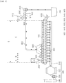
- FIG. 1 is a diagram schematically illustrating a sintering apparatus according to an exemplary embodiment of the present invention
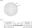
- FIG. 2 is a diagram schematically illustrating an injection unit according to the exemplary embodiment of the present invention.
- a sintering apparatus includes: a sintering trailer 100 installed to be movable along a sintering path S; a cooling unit 700, which is disposed at one side of the sintering path S, and cools a raw material discharged from the sintering trailer 100 by supplying cooling gas; a flue gas circulation line 800, which sucks at least a part of flue gas generated while a raw material is cooled in the cooling unit 700 and supplies the sucked flue gas to an upper portion of the sintering trailer 100; and a steam raw material supply unit 900, which is installed in the flue gas circulation line 800 and supplies a steam raw material into the flue gas circulation line 800.
- the sintering apparatus may further include a charging unit 200 for charging a raw material, an ignition furnace for igniting a raw material, a wind box 400 for sucking air inside the sintering trailer 100, a discharge unit 500 for discharging the sucked air to the outside, and a crusher 600 for crushing the raw material discharged from the sintering trailer 100.
- a charging unit 200 for charging a raw material
- an ignition furnace for igniting a raw material
- a wind box 400 for sucking air inside the sintering trailer 100
- a discharge unit 500 for discharging the sucked air to the outside
- a crusher 600 for crushing the raw material discharged from the sintering trailer 100.
- the sintering trailer 100 is arranged to rotate in a caterpillar manner, and forms a closed loop and moves along a movement path at an upper side and a movement path at a lower side.
- the movement path is formed of the sintering path S at the upper side and a returning path at the lower side, and in the sintering path S, the raw material is charged into the sintering trailer 100 and is ignited and sintered, and in the returning path, the empty sintering trailer 100 which distributes the sintering completed sintered ore moves and is returned to the sintering path S at the upper side.
- FIG. 1 illustrates the structure in which the sintering trailer 100 is arranged only in the sintering path S, but the sintering trailer 100 may be arranged throughout the entire movement paths including the sintering path S and the returning path and move along the movement paths as a matter of course.
- the sintering path S is extended in a longitudinal direction, and the sintering trailer 100 may move in a front direction and a rear direction of the sintering path S. Further, the sintering path S may include a charging section A which is located at the forefront of the sintering path S and in which the charging unit 200 is arranged, so that the raw material is charged into the sintering trailer 100, an ignition section B which is connected to a rear side of the charging section A, in which the ignition furnace 300 is disposed, so that fuel is ignited, and a sintering section C which is located to be connected to the rear side of the ignition section B and in which the raw material is sintered.
- a charging section A which is located at the forefront of the sintering path S and in which the charging unit 200 is arranged, so that the raw material is charged into the sintering trailer 100
- an ignition section B which is connected to a rear side of the charging section A, in which the ignition furnace 300 is disposed, so that fuel is ignited
- the charging section A is the section in which the raw material is charged or fed into the sintering trailer 100
- the ignition section B is the section in which the raw material is ignited
- the sintering section C is the section in which the raw material is sintered by moving flame ignited to an upper surface of the raw material downward.
- the flue gas circulation line 800 to be described below is connected to the sintering section C. That is, one side of the flue gas circulation line 800 is connected to the cooling unit 700, and the other side of the flue gas circulation line 800 is connected to a hood 820 disposed in the sintering section C. Accordingly, the flue gas sucked from the one side of the flue gas circulation line 800 is supplied to the upper portion of the sintering trailer 100 through the hood 820 installed at the other side of the flue gas circulation line 800.
- the sintering trailer 100 is formed with a space in which the raw material is accommodated therein, and a plurality of sintering trailers 100 may be installed in a caterpillar in one direction and move the sintering path S and the returning path. Accordingly, the sintering trailer 100 may charge the raw material into the sintering trailer 100 while moving the sintering path S and the returning path, and then sinter and discharge or distribute the raw material.
- the charging unit 200 is disposed in the charging section A in the sintering path S.
- the charging section may include a region having the same length as a length of the charging unit 200 according to the sintering path S.
- the charging unit 200 may be disposed in the upper portion of the sintering trailer 100, and may include a hopper forming a space in which the raw material is stored therein and a charging chute having an inclined surface so as to form a movement path of the raw material. Accordingly, when the hopper discharges the raw material in the down direction, the raw material may be guided into the sintering trailer 100 through the charging chute at the lower side.
- the ignition furnace 300 is disposed in the ignition section B of the sintering path S.
- the ignition section B may include a region having the same length as a length of the ignition furnace 300 according to the sintering path S.
- the ignition furnace 300 is disposed in the upper portion of the sintering trailer 100 and the rear side of the charging unit 200 to supply flame to the upper surface of the raw material within the sintering trailer 100 and ignite the raw material.
- a plurality of wind boxes 400 is disposed in the lower portion of the sintering trailer 100 along the sintering path S. More particularly, the wind boxes 400 may be provided throughout the sections including the ignition section B and the sintering section C.
- the wind box 400 sucks air in the down direction of the sintering trailer 100. Accordingly, air at the upper side of the sintering trailer 100 passes through the raw material in the sintering trailer 100 and is sucked to the lower wind box 400. Accordingly, the flame ignited to the upper surface of the raw material within the sintering trailer 100 by the air sucked by the wind box 400 moves to the lower surface of the raw material to sinter the raw material.
- the section in which the wind box 400 is provided is not limited thereto, and may be variously formed.
- the discharge unit 500 is connected to the plurality of wind boxes 400 to provide sucking force to the wind boxes 400, and discharges the sucked air to the outside.
- the discharge unit 500 includes a sucking chamber 510 which is connected to the lower portion of the plurality of wind boxes 400 and is formed with a space in which air is accommodated and is movable, a dust collector 520 provided in the sucking chamber 510, a main blower 530 disposed at the rear side of the dust collector 520 based on the air movement path, and a chimney 540 disposed at the rear side of the main blower 530.
- the main blower 530 when the main blower 530 generates sucking force, air is sucked from the upper side to the lower side through the wind box 400, and the sucked air passes through the dust collector 520 and is filtered while moving toward the main blower 530 along the sucking chamber 510 and then is discharged to the chimney 540 via the main blower 530. That is, the main blower 530 forms a negative pressure inside the wind box 400, thereby sucking air in the upper portion of the sintering trailer 100. In this case, air may move from the front side to the rear side within the sucking chamber 510.
- the crusher 600 may be disposed at one side of the sintering path, that is, a portion spaced apart from the rearmost portion of the sintering path. Accordingly, when the sintering is completed and the distributed sintered ore in the form of a lump is supplied to the crusher 600, the sintered ore is crushed by the crusher 600.
- the cooling unit 700 is disposed at one side of the sintering path and supplies cooling gas to the raw material discharged from the sintering trailer 100 and cools the raw material.
- the cooling unit 700 may be disposed while being spaced apart from the crusher 600, and is formed so as to have a space, in which the raw material, that is, the sintered ore, is accommodated, therein. Accordingly, when the sintered ore crushed in the crusher 600 is supplied to the cooling unit 700, the cooling gas may be supplied to the internal space through a cooling gas distributor, such as a nozzle. Accordingly, the cooling gas may absorb heat energy of the sintered ore while being in contact with and passing the sintered ore.
- the sintered ore is sorted to an appropriate size through the process and charged into the blast furnace (not illustrated), and the sintered ore having a small size may be classified into return ore and reused as a sintering raw material.
- the upper layer of the raw material is in contact with the outside and is deprived of heat energy by the outside air, so that upper layer of the raw material is difficult to increase a temperature compared to the lower layer, and even though a temperature is increased, a maintaining time of the high-temperature state may be short. Accordingly, a sintering reaction may insufficiently progress in the upper layer of the raw material, so that a quality and yieldability of the generated raw material may be degraded.
- the sintering apparatus is provided with the flue gas circulation line 800 and the steam raw material supply unit 900 to supply high-temperature flue gas and steam vaporized from the steam raw material to the upper portion of the sintering trailer 100 moving the sintering section C.
- the flue gas circulation line 800 is connected with the cooling unit 700 to serve to suck at least a part of flue gas generated while the cooling unit 700 cools the raw material and supply the sucked flue gas to the upper portion of the sintering trailer 100. More particularly, the flue gas circulation line 800 may suck at least a part of the high-temperature flue gas, which is supplied to the raw material, that is, the sintered ore, and absorbs heat energy within the cooling unit 700, to the upper portion of the sintering trailer 100.
- the flue gas circulation line 800 is extended so that one side thereof is connected to the cooling unit 700 and the other side is connected to the hood 820 disposed in the sintering section C.
- the flue gas circulation line 800 forms a path in which flue gas is accommodated and moves. Accordingly, the flue gas sucked from one side of the flue gas circulation line 800 is supplied to the upper portion of the sintering trailer 100 through the hood 820 installed at the other side of the flue gas circulation line 800 via the flue gas circulation line 800.
- the flue gas absorbs heat energy of the high-temperature raw material, so that the flue gas has a high temperature and includes dust generated in the raw material. Accordingly, when the high-temperature flue gas, which absorbs the heat energy of the raw material by cooling the raw material, is supplied to the upper portion of the sintering trailer 100 through the hood 820, the flue gas supplies heat energy to the charged raw material while passing through the raw material charged into the sintering trailer 100, and thus it is easier to combust the raw material and it is possible to prevent or suppress the temperature of the charged raw material from being decreased during the supply of the high-temperature flue gas.
- the hood 820 is disposed in the upper portion of the sintering trailer 100 within the sintering section C. Further, the hood 820 may be disposed in the sintering section C that is closer to the ignition section B than the rear portion of the sintering path S in the sintering section C. Further, the hood 820 may be extended along the sintering path S, and may be formed to be wider from the top to the bottom. Accordingly, the hood 820 may supply the flue gas from a start point of the sintering section C adjacent to the ignition section B to the upper portion of the sintering trailer 100.
- the flue gas circulation line 800 may further include a line blower 810 disposed in the movement path of the flue gas.
- the line blower 810 serves to provide sucking force to the one side of the flue gas. Accordingly, when the cooling unit 700 supplies cooling gas and the line blower 810 provides sucking force to one side of the flue gas circulation line 800, the cooling gas supplied to the raw material in the cooling unit 700 absorbs heat energy while passing through the raw material to be flue gas and then is sucked to one side of the flue gas circulation line 800, thereby preventing the flue gas from leaking to the outside of the cooling unit 700.
- the steam raw material supply unit 900 is installed in the flue gas circulation line 800 and supplies a steam raw material into the flue gas circulation line 800.
- the steam raw material is the raw material which absorbs heat energy from the flue gas moving inside the flue gas circulation line 800 to be vaporized into steam, and may be a fluid material including water which absorbs heat energy and is vaporized into steam.
- the steam raw material supply unit 900 may include: a storage unit 910 for storing the steam raw material, a control unit 920 connected to the storage unit 910 to control the amount of supply of the steam raw material; and an injection unit 930 connected to the control unit 920 and injects the steam raw material into the flue gas circulation line 800. Further, the steam raw material supply unit 900 may further include: a flue gas flow rate measuring unit 940 for measuring a flow rate of flue gas moving inside the flue gas circulation line 800; and a flue gas temperature measuring unit 950 for measuring a temperature of the flue gas inside the flue gas circulation line 800, and may further include a steam raw material temperature measuring unit (not illustrated) for measuring a temperature of the steam raw material stored in the storage unit 910.
- the flue gas flow rate measuring unit 940, the flue gas temperature measuring unit 950, and the steam raw material temperature measuring unit may be formed of various sensors for performing the functions, respectively.
- the steam raw material is stored in the storage unit 910, and the steam raw material stored in the storage unit 910 is supplied to the injection unit 930 through the control unit 920.
- the steam raw material supplied to the injection unit 930 is supplied into the flue gas circulation line 800, absorbs heat energy from the flue gas moving inside the flue gas circulation line 800, and is vaporized into steam.
- the control unit 920 is connected with the storage unit 910 and controls the amount of supply of the steam raw material supplied from the storage unit 910 to the injection unit 930.
- the control unit 920 may include a flow rate adjusting valve and the like for controlling the amount of supply of the steam raw material supplied from the storage unit 910, and the amount of supply of the steam raw material stored in the storage unit 910 is controlled by the control unit 920 to be supplied to the injection unit 930.
- control unit 920 may control the amount of steam raw material according to at least one of the flow rate of the flue gas moving inside the flue gas circulation line 800, the temperature of the flue gas inside the flue gas circulation line 800, and the temperature of the steam raw material stored in the storage unit 910, and the detailed configuration for controlling the amount of supply of the steam raw material supplied by the control unit 920 will be described below in relation to a sintering method according to an exemplary embodiment of the present invention.
- the injection unit 930 is connected to the control unit 920 to inject the steam raw material into the flue gas circulation line 800.
- the injection unit 930 may be installed to be introduced into the flue gas circulation line 800, or may be installed outside the flue gas circulation line 800 and have a nozzle structure communicating with an internal side of the flue gas circulation line 800, but may also have a structure including a housing which is connected with the control unit 920 to be connected to an external wall of the flue gas circulation line 800, and a plurality of injection holes 935 formed on the external wall of the flue gas circulation line 800.
- the injection unit 930 connected to the external wall of the flue gas circulation line 800 communicates with the inside of the flue gas circulation line 800 through the injection holes 935 and finely injects the steam raw material into the flue gas circulation line 800 through the injection holes 935, so that the steam raw material absorbs heat energy from the flue gas moving inside the flue gas circulation line 800 to be easily vaporized into steam.
- the flue gas absorbs heat energy of the high-temperature raw material, so that the flue gas has a high temperature. Accordingly, the steam raw material supplied from the steam raw material supply unit 900 into the flue gas circulation line 800 absorbs heat energy from at least a part of the high-temperature flue gas and is vaporized into steam. As described above, the steam vaporized from the steam raw material is supplied to the raw material inside the sintering trailer 100 through the hood 820 together with the flue gas sucked from the flue gas circulation line 800.
- the steam raw material may be a fluid material including water.
- the flue gas circulation line 800 supplies vapor (H 2 O) to the upper portion of the sintering trailer 100 together with the flue gas.
- FIG. 3 is a diagram for describing a process of combusting fuel in a sintering process
- FIG. 4 is a diagram illustrating a content of gas discharged in the sintering process.
- Combustion efficiency of fuel in the sintering process is determined by a ratio of carbon dioxide (CO 2 ) to a content of carbon monoxide (CO) and carbon dioxide (CO 2 ).
- CO 2 carbon dioxide
- CO 2 carbon dioxide
- the raw material When vapor is not supplied to the raw material, the raw material is incompletely combusted like a chemical formula illustrated in FIG. 3 , so that carbon monoxide (CO) is discharged. However, when vapor is supplied to the raw material, the vapor reacts carbon monoxide (CO) (H 2 O-CO reaction) discharged during the incomplete combustion to generate hydrogen (H 2 ) and carbon dioxide (CO 2 ). By the reaction, the raw material is completely combusted like a chemical formula illustrated in FIG. 3 and combustion efficiency is improved.
- CO carbon monoxide
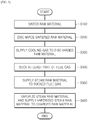
- FIG. 5 is a diagram schematically illustrating a sintering method according to an exemplary embodiment of the present invention.
- the sintering method includes: sintering a raw material within a sintering trailer 100 moving along a sintering path (S100); discharging the sintered raw material from the sintering trailer 100 (S200); supplying cooling gas and cooling the discharged raw material (S300); sucking at least a part of flue gas generated while cooling the raw material (S400); supplying a steam raw material to the sucked flue gas (S500); and vaporizing the steam raw material and supplying the vaporized steam raw material to the raw material charged into the sintering trailer 100 together with the sucked flue gas (S600).
- the sintering of the raw material includes sintering the raw material within the sintering trailer 100 moving along the sintering path.
- a raw material layer is formed by charging the raw material into each of the plurality of sintering trailers 100 through the charging unit 200 by making the plurality of sintering trailers 100 sequentially pass through a lower side of the charging unit 200.
- flame is ignited to an upper portion of the raw material layer by the ignition furnace 300 and each sintering trailer 100 sinters the raw material via a sintering section C.
- the flame of the upper portion of the raw material layer moves downward by sucking force of wind boxes 400 within the sintering section and combusts the raw material to produce sintered ore.
- the discharging of the sintered raw material from the sintering trailer 100 includes discharging the sintering-completed raw material, that is, sintered ore, from the sintering trailer 100.
- the discharged raw material may be crushed and transferred to a cooling unit 700.
- the cooling of the discharged raw material includes cooling the discharged raw material by supplying cooling gas to the discharged raw material.
- the sucking of at least the part of flue gas generated while cooling the raw material (S400) includes sucking at least a part of high-temperature flue gas that is supplied to the sintered ore and absorbs heat energy within the cooling unit 700 from one side of a flue gas circulation line 800.
- the flue gas circulation line 800 is extended so that one side thereof is connected to the cooling unit 700 and the other side thereof is connected to a hood 820 disposed in the sintering section C, so that the flue gas sucked from one side of the flue gas circulation line 800 is supplied to the upper portion of the sintering trailer 100 through the hood 820 installed at the other side of the flue gas circulation line 800 via the flue gas circulation line 800, which has been described above.
- the supplying of the steam raw material to the sucked flue gas (S500) includes supplying the steam raw material into the flue gas circulation line 800 by a steam raw material supply unit 900 installed in the flue gas circulation line 800.
- the steam raw material is the raw material which absorbs heat energy from the flue gas moving inside the flue gas circulation line 800 to be vaporized into steam, and may be a fluid material including water which absorbs heat energy and is vaporized into steam.
- the supplying of the steam raw material may include: preparing the steam raw material; controlling the amount of supply of the prepared steam raw material; and injecting the steam raw material of which the amount of supply is controlled to the sucked flue gas.
- the steam raw material is stored in a storage unit 910 to be prepared, and in the controlling of the amount of supply of the prepared steam raw material, the amount of supply of the steam raw material supplied from the storage unit 910 to an injection unit 930 is controlled through a control unit 920.
- the injecting of the steam raw material, of which the amount of supply is controlled, to the sucked flue gas includes injecting the steam raw material into the flue gas circulation line 800 by the injection unit 930 connected with the control unit 920.
- the steam raw material supplied to the injection unit 930 is supplied into the flue gas circulation line 800, absorbs heat energy from the flue gas moving inside the flue gas circulation line 800, and is vaporized into steam.
- the amount of supply of the steam raw material supplied into the flue gas circulation line 800 may be controlled to be proportional to a flow rate of the flue gas sucked from one side of the flue gas circulation line 800. That is, when a flow rate of the flue gas that is sucked from the cooling unit 700 and moves through the flue gas circulation line 800 is increased, more flue gas moves into the flue gas circulation line 800 and the amount of heat energy of the flue gas is also increased, so that the amount of supply of the steam raw material supplied into the flue gas circulation line 800 may be increased.
- the amount of supply of the steam raw material when a temperature of the sucked flue gas is increased, the amount of supply of the steam raw material may be increased, and even when a temperature of the steam raw material prepared in the storage unit 910 is increased, the amount of supply of the steam raw material may be increased. This is because when the flue gas has a high temperature, the amount of heat energy of the flue gas is increased, and when the stored steam raw material has a high temperature, the amount of heat energy required for vaporizing the steam raw material is decreased.
- the amount of supply of the steam raw material may be controlled according to at least one of a flow rate Q of the flue gas moving inside the flue gas circulation line 800, a temperature T of the flue gas inside the flue gas circulation line 800, and a temperature t of the steam raw material stored in the storage unit 910.
- the amount q of supply of the steam raw material in consideration of the flow rate Q of the flue gas, the temperature T of the flue gas, and the temperature t of the steam raw material may be controlled to the range of Equation 1 below.
- Equation 1 is derived from a correlation between the flow rate Q of the flue gas and the temperature t of the steam raw material and a correlation between the temperature T of the flue gas and the temperature t of the steam raw material, and the amount q of supply of the steam raw material is controlled to the range that is equal to or larger than a minimum value described at the left side of Equation 1 and is equal to or smaller than a maximum value described at the right side.
- the amount q of supply of the steam raw material when the amount q of supply of the steam raw material is smaller than the minimum value described at the left side of Equation 1, the amount of vapor supplied to the upper portion of the sintering trailer 100 from the flue gas circulation line 800 is not sufficient, and when the amount q of supply of the steam raw material is larger than the maximum value described at the right side of Equation 1, the steam raw material, which fails to be sufficiently vaporized within the flue gas circulation line 800, is discharged to the upper portion of the sintering trailer 100 from the flue gas circulation line 800.
- the process of vaporizing the steam raw material supplied from the steam raw material supply unit 900 and supplying the vaporized steam raw material to the sintering trailer 100 together with the sucked flue gas (S600) is performed.
- the steam raw material absorbs heat energy of the sucked flue gas and is vaporized into steam, and by controlling the amount of supply of the steam raw material to the range of Equation 1 as described above, it is possible to efficiently vaporize the steam raw material within the flue gas circulation line 800 by utilizing heat energy of the flue gas moving inside the flue gas circulation line 800 and simultaneously supply the sufficient amount of vapor to the upper portion of the sintering trailer 100.
- a raw material is completely combusted by supplying steam to the upper portion of the sintering trailer 100 together with high-temperature flue gas, thereby improving combustion efficiency and decreasing the amount of carbon dioxide (CO 2 ) generated.
- the sintered ore produced in the upper layer of the raw material has improved strength and an increased recovery rate, thereby improving yieldability.
Landscapes
- Engineering & Computer Science (AREA)
- Mechanical Engineering (AREA)
- Environmental & Geological Engineering (AREA)
- Chemical & Material Sciences (AREA)
- General Engineering & Computer Science (AREA)
- Life Sciences & Earth Sciences (AREA)
- General Life Sciences & Earth Sciences (AREA)
- Geochemistry & Mineralogy (AREA)
- Geology (AREA)
- Manufacturing & Machinery (AREA)
- Materials Engineering (AREA)
- Metallurgy (AREA)
- Organic Chemistry (AREA)
- Waste-Gas Treatment And Other Accessory Devices For Furnaces (AREA)
- Manufacture And Refinement Of Metals (AREA)
- Furnace Details (AREA)
Abstract
Description
- The present invention relates to a sintering apparatus and a sintering method using the same, and more particularly, to a sintering apparatus capable of controlling a combustion process of a raw material, thereby improving a quality and yieldability of the raw material, and a sintering method using the same.
- In general, in a sintering process, iron ore, subsidiary materials, and (powder coke, anthracite coal), and the like are put into a drum mixer, mixed and humidified, and then charged into a sintering trailer at a predetermined height. Then, sintering of the sintered mixed materials proceeds by forcibly sucking air from a lower portion after the surface ignition by an ignition furnace, and sintered ore is produced. Then, the sintering completed sintered ore is distributed and is cooled in a cooler via a crusher, and the sintered ore, which has a particular size that is easy to be charged into a blast furnace and easy for reaction in the blast furnace, is transferred to the blast furnace, and fine ore that is the sintered ore having a small size is classified into return ore and is used as a sintering raw material again.
- The sintering process is performed by applying sucking force to the sintering trailer by forming a negative pressure in a wind box disposed in a lower portion of the sintering trailer. That is, when a main blower is driven, a negative pressure is formed in the wind box, and the mixed raw material loaded in the sintering trailer is sintered downward while air is sucked from a lower portion in the ignited surface by the formed negative pressure. Then, the sintering completed raw material is cooled by cooler gas injected in the cooler via the crusher.
- However, the raw material within the sintering trailer has different combustion behaviors depending on each region, and because an upper layer of the raw material is in contact with the outside and is deprived of heat energy by the outside air, the upper layer of the raw material is difficult to increase a temperature compared to a lower layer, and even though the temperature of the upper layer of the raw material is increased, a maintaining time of the high-temperature state of the upper layer of the raw material may be short. Accordingly, since the sintering reaction may insufficiently progress in the upper layer of the raw material, there is a problem in that a quality and yieldability of a produced raw material are degraded.
- Korean Patent Application Publication No.
10-2014-0016658 - The present invention provides a sintering apparatus capable of controlling a sintering process of a raw material, and a sintering method.
- Further, the present invention provides a sintering apparatus capable of improving a quality and yieldability of a raw material, and a sintering method using the same.
- A sintering apparatus according to an exemplary embodiment of the present invention includes: a sintering trailer installed to be movable along a sintering path; a cooling unit disposed at one side of the sintering path, and configured to supply cooling gas and cool a raw material discharged from the sintering trailer; a flue gas circulation line configured to suck at least a part of flue gas generated while cooling the raw material in the cooling unit and supply the sucked flue gas to an upper portion of the sintering trailer; and a steam raw material supply unit installed in the flue gas circulation line and configured to supply a steam raw material into the flue gas circulation line.
- The steam raw material supply unit may include: a storage unit configured to store a steam raw material; a control unit connected to the storage unit and configured to control the amount of supply of the steam raw material; and an injection unit connected to the control unit and configured to inject the steam raw material into the flue gas circulation line.
- The injection unit may include a plurality of injection holes communicating with an internal side of the flue gas circulation line.
- The steam raw material supply unit may include: a flue gas flow rate measuring unit configured to measure a flow rate of the flue gas moving inside the flue gas circulation line; and a flue gas temperature measuring unit configured to measure a temperature of the flue gas inside the flue gas circulation line.
- The steam raw material supply unit may further include a steam raw material temperature measuring unit which measures a temperature of the steam raw material stored in the storage unit.
- The control unit may control the amount of supply of the steam raw material according to at least one of a flow rate of the flue gas moving inside the flue gas circulation line, a temperature of the flue gas inside the flue gas circulation line, and a temperature of the steam raw material stored in the storage unit.
- The sintering path may include: a charging section in which the raw material is charged into the sintering trailer; an ignition section which is connected to the charging section and in which the raw material is ignited; and a sintering section which is connected to the ignition section and in which the raw material is sintered, and the flue gas circulation line may be connected to the sintering section adjacent to the ignition section.
- The steam raw material supplied to the flue gas circulation line may contain water, and the flue gas circulation line may supply vapor (H2O) to the upper portion of the sintering trailer together with the flue gas.
- Further, a sintering method according to an exemplary embodiment of the present invention includes: sintering a raw material within a sintering trailer moving along a sintering path; discharging the sintered raw material from the sintering trailer; supplying cooling gas and cooling the discharged raw material; sucking at least a part of flue gas generated while cooling the raw material; supplying a steam raw material to the sucked flue gas; and vaporizing the steam raw material and supplying the vaporized steam raw material to the raw material charged into the sintering trailer together with the sucked flue gas.
- The supplying of the steam raw material may include: preparing the steam raw material; controlling the amount of supply of the prepared steam raw material; and injecting the steam raw material, of which the amount of supply is controlled, to the sucked flue gas.
- In the vaporizing of the steam raw material and the supplying of the vaporized steam raw material to the raw material charged into the sintering trailer together with the sucked flue gas, the steam raw material may absorb heat energy of the sucked flue gas and is vaporized into steam.
- The controlling of the amount of supply of the steam raw material may include controlling the amount of supply of the steam raw material to be proportional to a flow rate of the sucked flue gas.
- The controlling of the amount of supply of the steam raw material may include increasing the amount of supply of the steam raw material when a temperature of the sucked flue gas is increased.
- The controlling of the amount of supply of the steam raw material may include increasing the amount of supply of the steam raw material when a temperature of the prepared steam raw material is increased.
- The controlling of the amount of supply of the steam raw material may include controlling the amount of supply of the steam raw material to the range of Equation 1 below.

- According to the sintering apparatus and the sintering method using the same according to the exemplary embodiment of the present invention, a raw material is completely combusted by supplying steam together with high-temperature flue gas to an upper portion of a sintering trailer, thereby improving combustion efficiency and decreasing the amount of generation of carbon dioxide (CO2).
- Further, in generating steam supplied to the upper portion of the sintering trailer, it is possible to sufficiently supply steam to the upper portion of the sintering trailer while minimizing a use of external heat energy by utilizing heat energy of the flue gas discharged in a cooling process of sintered ore.
- In addition, by the foregoing improvement of the combustion efficiency, it is possible to obtain more calories from the same amount of fuel, and by the additional calories obtained in this case, the sintered ore produced in the upper layer of the raw material has improved strength and an increased recovery rate, thereby improving yieldability.
-
-
FIG. 1 is a diagram schematically illustrating a sintering apparatus according to an exemplary embodiment of the present invention. -
FIG. 2 is a diagram schematically illustrating an injection unit according to the exemplary embodiment of the present invention. -
FIG. 3 is a diagram for describing a process of combusting fuel in a sintering process. -
FIG. 4 is a diagram illustrating a content of gas discharged in the sintering process. -
FIG. 5 is a diagram schematically illustrating a sintering method according to an exemplary embodiment of the present invention. - Hereinafter, an exemplary embodiment of the present invention will be described in detail with reference to the accompanying drawings. However,, the present disclosure is not limited to exemplary embodiments disclosed herein but will be implemented in various forms, and the exemplary embodiments are provided so that the present invention is completely disclosed, and a person of ordinary skilled in the art can fully understand the scope of the present invention. Throughout the drawings, like elements are designated by like reference numerals.
-
FIG. 1 is a diagram schematically illustrating a sintering apparatus according to an exemplary embodiment of the present invention, andFIG. 2 is a diagram schematically illustrating an injection unit according to the exemplary embodiment of the present invention. - Referring to
FIGS. 1 and2 , a sintering apparatus according to an exemplary embodiment of the present invention includes: asintering trailer 100 installed to be movable along a sintering path S; acooling unit 700, which is disposed at one side of the sintering path S, and cools a raw material discharged from thesintering trailer 100 by supplying cooling gas; a fluegas circulation line 800, which sucks at least a part of flue gas generated while a raw material is cooled in thecooling unit 700 and supplies the sucked flue gas to an upper portion of thesintering trailer 100; and a steam raw material supply unit 900, which is installed in the fluegas circulation line 800 and supplies a steam raw material into the fluegas circulation line 800. Herein, the sintering apparatus according to the exemplary embodiment of the present invention may further include acharging unit 200 for charging a raw material, an ignition furnace for igniting a raw material, awind box 400 for sucking air inside thesintering trailer 100, adischarge unit 500 for discharging the sucked air to the outside, and acrusher 600 for crushing the raw material discharged from thesintering trailer 100. - The
sintering trailer 100 is arranged to rotate in a caterpillar manner, and forms a closed loop and moves along a movement path at an upper side and a movement path at a lower side. The movement path is formed of the sintering path S at the upper side and a returning path at the lower side, and in the sintering path S, the raw material is charged into thesintering trailer 100 and is ignited and sintered, and in the returning path, the emptysintering trailer 100 which distributes the sintering completed sintered ore moves and is returned to the sintering path S at the upper side.FIG. 1 illustrates the structure in which thesintering trailer 100 is arranged only in the sintering path S, but thesintering trailer 100 may be arranged throughout the entire movement paths including the sintering path S and the returning path and move along the movement paths as a matter of course. - The sintering path S is extended in a longitudinal direction, and the
sintering trailer 100 may move in a front direction and a rear direction of the sintering path S. Further, the sintering path S may include a charging section A which is located at the forefront of the sintering path S and in which thecharging unit 200 is arranged, so that the raw material is charged into thesintering trailer 100, an ignition section B which is connected to a rear side of the charging section A, in which theignition furnace 300 is disposed, so that fuel is ignited, and a sintering section C which is located to be connected to the rear side of the ignition section B and in which the raw material is sintered. That is, the charging section A is the section in which the raw material is charged or fed into thesintering trailer 100, the ignition section B is the section in which the raw material is ignited, and the sintering section C is the section in which the raw material is sintered by moving flame ignited to an upper surface of the raw material downward. - In this case, the flue
gas circulation line 800 to be described below is connected to the sintering section C. That is, one side of the fluegas circulation line 800 is connected to thecooling unit 700, and the other side of the fluegas circulation line 800 is connected to ahood 820 disposed in the sintering section C. Accordingly, the flue gas sucked from the one side of the fluegas circulation line 800 is supplied to the upper portion of thesintering trailer 100 through thehood 820 installed at the other side of the fluegas circulation line 800. - The
sintering trailer 100 is formed with a space in which the raw material is accommodated therein, and a plurality of sinteringtrailers 100 may be installed in a caterpillar in one direction and move the sintering path S and the returning path. Accordingly, thesintering trailer 100 may charge the raw material into thesintering trailer 100 while moving the sintering path S and the returning path, and then sinter and discharge or distribute the raw material. - The
charging unit 200 is disposed in the charging section A in the sintering path S. Herein, the charging section may include a region having the same length as a length of thecharging unit 200 according to the sintering path S. Thecharging unit 200 may be disposed in the upper portion of thesintering trailer 100, and may include a hopper forming a space in which the raw material is stored therein and a charging chute having an inclined surface so as to form a movement path of the raw material. Accordingly, when the hopper discharges the raw material in the down direction, the raw material may be guided into thesintering trailer 100 through the charging chute at the lower side. - The
ignition furnace 300 is disposed in the ignition section B of the sintering path S. Herein, the ignition section B may include a region having the same length as a length of theignition furnace 300 according to the sintering path S. Theignition furnace 300 is disposed in the upper portion of thesintering trailer 100 and the rear side of thecharging unit 200 to supply flame to the upper surface of the raw material within thesintering trailer 100 and ignite the raw material. - A plurality of
wind boxes 400 is disposed in the lower portion of thesintering trailer 100 along the sintering path S. More particularly, thewind boxes 400 may be provided throughout the sections including the ignition section B and the sintering section C. Thewind box 400 sucks air in the down direction of thesintering trailer 100. Accordingly, air at the upper side of thesintering trailer 100 passes through the raw material in thesintering trailer 100 and is sucked to thelower wind box 400. Accordingly, the flame ignited to the upper surface of the raw material within thesintering trailer 100 by the air sucked by thewind box 400 moves to the lower surface of the raw material to sinter the raw material. However, the section in which thewind box 400 is provided is not limited thereto, and may be variously formed. - The
discharge unit 500 is connected to the plurality ofwind boxes 400 to provide sucking force to thewind boxes 400, and discharges the sucked air to the outside. Thedischarge unit 500 includes a suckingchamber 510 which is connected to the lower portion of the plurality ofwind boxes 400 and is formed with a space in which air is accommodated and is movable, adust collector 520 provided in the suckingchamber 510, amain blower 530 disposed at the rear side of thedust collector 520 based on the air movement path, and achimney 540 disposed at the rear side of themain blower 530. Accordingly, when themain blower 530 generates sucking force, air is sucked from the upper side to the lower side through thewind box 400, and the sucked air passes through thedust collector 520 and is filtered while moving toward themain blower 530 along the suckingchamber 510 and then is discharged to thechimney 540 via themain blower 530. That is, themain blower 530 forms a negative pressure inside thewind box 400, thereby sucking air in the upper portion of thesintering trailer 100. In this case, air may move from the front side to the rear side within the suckingchamber 510. - The
crusher 600 may be disposed at one side of the sintering path, that is, a portion spaced apart from the rearmost portion of the sintering path. Accordingly, when the sintering is completed and the distributed sintered ore in the form of a lump is supplied to thecrusher 600, the sintered ore is crushed by thecrusher 600. - The
cooling unit 700 is disposed at one side of the sintering path and supplies cooling gas to the raw material discharged from thesintering trailer 100 and cools the raw material. Thecooling unit 700 may be disposed while being spaced apart from thecrusher 600, and is formed so as to have a space, in which the raw material, that is, the sintered ore, is accommodated, therein. Accordingly, when the sintered ore crushed in thecrusher 600 is supplied to thecooling unit 700, the cooling gas may be supplied to the internal space through a cooling gas distributor, such as a nozzle. Accordingly, the cooling gas may absorb heat energy of the sintered ore while being in contact with and passing the sintered ore. The sintered ore is sorted to an appropriate size through the process and charged into the blast furnace (not illustrated), and the sintered ore having a small size may be classified into return ore and reused as a sintering raw material. - Herein, when the raw material within the
sintering trailer 100 is sintered, the upper layer of the raw material is in contact with the outside and is deprived of heat energy by the outside air, so that upper layer of the raw material is difficult to increase a temperature compared to the lower layer, and even though a temperature is increased, a maintaining time of the high-temperature state may be short. Accordingly, a sintering reaction may insufficiently progress in the upper layer of the raw material, so that a quality and yieldability of the generated raw material may be degraded. Accordingly, the sintering apparatus according to the exemplary embodiment of the present invention is provided with the fluegas circulation line 800 and the steam raw material supply unit 900 to supply high-temperature flue gas and steam vaporized from the steam raw material to the upper portion of thesintering trailer 100 moving the sintering section C. - The flue
gas circulation line 800 is connected with thecooling unit 700 to serve to suck at least a part of flue gas generated while thecooling unit 700 cools the raw material and supply the sucked flue gas to the upper portion of thesintering trailer 100. More particularly, the fluegas circulation line 800 may suck at least a part of the high-temperature flue gas, which is supplied to the raw material, that is, the sintered ore, and absorbs heat energy within thecooling unit 700, to the upper portion of thesintering trailer 100. - The flue
gas circulation line 800 is extended so that one side thereof is connected to thecooling unit 700 and the other side is connected to thehood 820 disposed in the sintering section C. The fluegas circulation line 800 forms a path in which flue gas is accommodated and moves. Accordingly, the flue gas sucked from one side of the fluegas circulation line 800 is supplied to the upper portion of thesintering trailer 100 through thehood 820 installed at the other side of the fluegas circulation line 800 via the fluegas circulation line 800. - The flue gas absorbs heat energy of the high-temperature raw material, so that the flue gas has a high temperature and includes dust generated in the raw material. Accordingly, when the high-temperature flue gas, which absorbs the heat energy of the raw material by cooling the raw material, is supplied to the upper portion of the
sintering trailer 100 through thehood 820, the flue gas supplies heat energy to the charged raw material while passing through the raw material charged into thesintering trailer 100, and thus it is easier to combust the raw material and it is possible to prevent or suppress the temperature of the charged raw material from being decreased during the supply of the high-temperature flue gas. - The
hood 820 is disposed in the upper portion of thesintering trailer 100 within the sintering section C. Further, thehood 820 may be disposed in the sintering section C that is closer to the ignition section B than the rear portion of the sintering path S in the sintering section C. Further, thehood 820 may be extended along the sintering path S, and may be formed to be wider from the top to the bottom. Accordingly, thehood 820 may supply the flue gas from a start point of the sintering section C adjacent to the ignition section B to the upper portion of thesintering trailer 100. - The flue
gas circulation line 800 may further include aline blower 810 disposed in the movement path of the flue gas. Theline blower 810 serves to provide sucking force to the one side of the flue gas. Accordingly, when thecooling unit 700 supplies cooling gas and theline blower 810 provides sucking force to one side of the fluegas circulation line 800, the cooling gas supplied to the raw material in thecooling unit 700 absorbs heat energy while passing through the raw material to be flue gas and then is sucked to one side of the fluegas circulation line 800, thereby preventing the flue gas from leaking to the outside of thecooling unit 700. - The steam raw material supply unit 900 is installed in the flue
gas circulation line 800 and supplies a steam raw material into the fluegas circulation line 800. Herein, the steam raw material is the raw material which absorbs heat energy from the flue gas moving inside the fluegas circulation line 800 to be vaporized into steam, and may be a fluid material including water which absorbs heat energy and is vaporized into steam. - The steam raw material supply unit 900 may include: a
storage unit 910 for storing the steam raw material, acontrol unit 920 connected to thestorage unit 910 to control the amount of supply of the steam raw material; and aninjection unit 930 connected to thecontrol unit 920 and injects the steam raw material into the fluegas circulation line 800. Further, the steam raw material supply unit 900 may further include: a flue gas flowrate measuring unit 940 for measuring a flow rate of flue gas moving inside the fluegas circulation line 800; and a flue gastemperature measuring unit 950 for measuring a temperature of the flue gas inside the fluegas circulation line 800, and may further include a steam raw material temperature measuring unit (not illustrated) for measuring a temperature of the steam raw material stored in thestorage unit 910. The flue gas flowrate measuring unit 940, the flue gastemperature measuring unit 950, and the steam raw material temperature measuring unit may be formed of various sensors for performing the functions, respectively. - The steam raw material is stored in the
storage unit 910, and the steam raw material stored in thestorage unit 910 is supplied to theinjection unit 930 through thecontrol unit 920. Herein, the steam raw material supplied to theinjection unit 930 is supplied into the fluegas circulation line 800, absorbs heat energy from the flue gas moving inside the fluegas circulation line 800, and is vaporized into steam. - The
control unit 920 is connected with thestorage unit 910 and controls the amount of supply of the steam raw material supplied from thestorage unit 910 to theinjection unit 930. Thecontrol unit 920 may include a flow rate adjusting valve and the like for controlling the amount of supply of the steam raw material supplied from thestorage unit 910, and the amount of supply of the steam raw material stored in thestorage unit 910 is controlled by thecontrol unit 920 to be supplied to theinjection unit 930. Herein, thecontrol unit 920 may control the amount of steam raw material according to at least one of the flow rate of the flue gas moving inside the fluegas circulation line 800, the temperature of the flue gas inside the fluegas circulation line 800, and the temperature of the steam raw material stored in thestorage unit 910, and the detailed configuration for controlling the amount of supply of the steam raw material supplied by thecontrol unit 920 will be described below in relation to a sintering method according to an exemplary embodiment of the present invention. - The
injection unit 930 is connected to thecontrol unit 920 to inject the steam raw material into the fluegas circulation line 800. Theinjection unit 930 may be installed to be introduced into the fluegas circulation line 800, or may be installed outside the fluegas circulation line 800 and have a nozzle structure communicating with an internal side of the fluegas circulation line 800, but may also have a structure including a housing which is connected with thecontrol unit 920 to be connected to an external wall of the fluegas circulation line 800, and a plurality of injection holes 935 formed on the external wall of the fluegas circulation line 800. Theinjection unit 930 connected to the external wall of the fluegas circulation line 800 communicates with the inside of the fluegas circulation line 800 through the injection holes 935 and finely injects the steam raw material into the fluegas circulation line 800 through the injection holes 935, so that the steam raw material absorbs heat energy from the flue gas moving inside the fluegas circulation line 800 to be easily vaporized into steam. - The flue gas absorbs heat energy of the high-temperature raw material, so that the flue gas has a high temperature. Accordingly, the steam raw material supplied from the steam raw material supply unit 900 into the flue
gas circulation line 800 absorbs heat energy from at least a part of the high-temperature flue gas and is vaporized into steam. As described above, the steam vaporized from the steam raw material is supplied to the raw material inside thesintering trailer 100 through thehood 820 together with the flue gas sucked from the fluegas circulation line 800. - As described above, the steam raw material may be a fluid material including water. In this case, the flue
gas circulation line 800 supplies vapor (H2O) to the upper portion of thesintering trailer 100 together with the flue gas. -
FIG. 3 is a diagram for describing a process of combusting fuel in a sintering process, andFIG. 4 is a diagram illustrating a content of gas discharged in the sintering process. - Combustion efficiency of fuel in the sintering process is determined by a ratio of carbon dioxide (CO2) to a content of carbon monoxide (CO) and carbon dioxide (CO2). Herein, when the combustion efficiency of the raw material is increased, the amount of calories generated is increased when the same amount of fuel is used, so that real yieldability of the sintered ore may be improved and the amount of carbon dioxide (CO2) generated may be decreased.
- When vapor is not supplied to the raw material, the raw material is incompletely combusted like a chemical formula illustrated in
FIG. 3 , so that carbon monoxide (CO) is discharged. However, when vapor is supplied to the raw material, the vapor reacts carbon monoxide (CO) (H2O-CO reaction) discharged during the incomplete combustion to generate hydrogen (H2) and carbon dioxide (CO2). By the reaction, the raw material is completely combusted like a chemical formula illustrated inFIG. 3 and combustion efficiency is improved. - This can be seen from the experimental result of
FIG. 4 . That is, investigating the amount of carbon dioxide (CO2) and oxygen (O2) discharged illustrated in (a) ofFIG. 4 and the content of discharge gas of carbon monoxide (CO), hydrogen (H2), and methane (CH4) illustrated in (b) ofFIG. 4 , it can be seen that hydrogen (H2) is sharply generated at the end of combustion, and the vapor supplied to the raw material reacts (water-gas reaction) with carbon monoxide (CO) to be decomposed into hydrogen (H2), and combustion efficiency of the raw material is improved through the reaction, and the decomposed hydrogen (H2) is reoxidized at a high temperature and thus effective calories are increased. That is, it is possible to obtain more calories from the same amount of fuel through the improvement of the fuel efficiency, and in this case, and by the additional calories obtained in this case, strength of the sintered ore produced in the upper layer of the raw material is improved and a recovery rate of the sintered ore is increased. - Hereinafter, a sintering method according to an exemplary embodiment of the present invention will be described. Herein, overlapping description to the foregoing contents related to the sintering apparatus according to the exemplary embodiment of the present invention will be omitted.
-
FIG. 5 is a diagram schematically illustrating a sintering method according to an exemplary embodiment of the present invention. - Referring to
FIG. 5 , the sintering method according to the exemplary embodiment of the present invention includes: sintering a raw material within asintering trailer 100 moving along a sintering path (S100); discharging the sintered raw material from the sintering trailer 100 (S200); supplying cooling gas and cooling the discharged raw material (S300); sucking at least a part of flue gas generated while cooling the raw material (S400); supplying a steam raw material to the sucked flue gas (S500); and vaporizing the steam raw material and supplying the vaporized steam raw material to the raw material charged into thesintering trailer 100 together with the sucked flue gas (S600). - The sintering of the raw material (S100) includes sintering the raw material within the
sintering trailer 100 moving along the sintering path. First, a raw material layer is formed by charging the raw material into each of the plurality ofsintering trailers 100 through the chargingunit 200 by making the plurality ofsintering trailers 100 sequentially pass through a lower side of the chargingunit 200. When the plurality ofsintering trailers 100 sequentially passes through the lower side of anignition furnace 300, flame is ignited to an upper portion of the raw material layer by theignition furnace 300 and eachsintering trailer 100 sinters the raw material via a sintering section C. That is, in the process in which thesintering trailer 100 moves along the sintering section C, the flame of the upper portion of the raw material layer moves downward by sucking force ofwind boxes 400 within the sintering section and combusts the raw material to produce sintered ore. - The discharging of the sintered raw material from the sintering trailer 100 (S200) includes discharging the sintering-completed raw material, that is, sintered ore, from the
sintering trailer 100. Herein, the discharged raw material may be crushed and transferred to acooling unit 700. Further, the cooling of the discharged raw material (S300) includes cooling the discharged raw material by supplying cooling gas to the discharged raw material. - The sucking of at least the part of flue gas generated while cooling the raw material (S400) includes sucking at least a part of high-temperature flue gas that is supplied to the sintered ore and absorbs heat energy within the
cooling unit 700 from one side of a fluegas circulation line 800. Herein, the fluegas circulation line 800 is extended so that one side thereof is connected to thecooling unit 700 and the other side thereof is connected to ahood 820 disposed in the sintering section C, so that the flue gas sucked from one side of the fluegas circulation line 800 is supplied to the upper portion of thesintering trailer 100 through thehood 820 installed at the other side of the fluegas circulation line 800 via the fluegas circulation line 800, which has been described above. - The supplying of the steam raw material to the sucked flue gas (S500) includes supplying the steam raw material into the flue
gas circulation line 800 by a steam raw material supply unit 900 installed in the fluegas circulation line 800. Herein, the steam raw material is the raw material which absorbs heat energy from the flue gas moving inside the fluegas circulation line 800 to be vaporized into steam, and may be a fluid material including water which absorbs heat energy and is vaporized into steam. - Herein, the supplying of the steam raw material (S500) may include: preparing the steam raw material; controlling the amount of supply of the prepared steam raw material; and injecting the steam raw material of which the amount of supply is controlled to the sucked flue gas.
- In the preparing of the steam raw material, the steam raw material is stored in a
storage unit 910 to be prepared, and in the controlling of the amount of supply of the prepared steam raw material, the amount of supply of the steam raw material supplied from thestorage unit 910 to aninjection unit 930 is controlled through acontrol unit 920. Further, the injecting of the steam raw material, of which the amount of supply is controlled, to the sucked flue gas includes injecting the steam raw material into the fluegas circulation line 800 by theinjection unit 930 connected with thecontrol unit 920. Herein, the steam raw material supplied to theinjection unit 930 is supplied into the fluegas circulation line 800, absorbs heat energy from the flue gas moving inside the fluegas circulation line 800, and is vaporized into steam. - Herein, in the controlling of the amount of supply of the steam raw material, the amount of supply of the steam raw material supplied into the flue
gas circulation line 800 may be controlled to be proportional to a flow rate of the flue gas sucked from one side of the fluegas circulation line 800. That is, when a flow rate of the flue gas that is sucked from thecooling unit 700 and moves through the fluegas circulation line 800 is increased, more flue gas moves into the fluegas circulation line 800 and the amount of heat energy of the flue gas is also increased, so that the amount of supply of the steam raw material supplied into the fluegas circulation line 800 may be increased. - Further, in the controlling of the amount of supply of the steam raw material, when a temperature of the sucked flue gas is increased, the amount of supply of the steam raw material may be increased, and even when a temperature of the steam raw material prepared in the
storage unit 910 is increased, the amount of supply of the steam raw material may be increased. This is because when the flue gas has a high temperature, the amount of heat energy of the flue gas is increased, and when the stored steam raw material has a high temperature, the amount of heat energy required for vaporizing the steam raw material is decreased. - As described above, in the controlling of the amount of supply of the steam raw material, the amount of supply of the steam raw material may be controlled according to at least one of a flow rate Q of the flue gas moving inside the flue
gas circulation line 800, a temperature T of the flue gas inside the fluegas circulation line 800, and a temperature t of the steam raw material stored in thestorage unit 910. Herein, the amount q of supply of the steam raw material in consideration of the flow rate Q of the flue gas, the temperature T of the flue gas, and the temperature t of the steam raw material may be controlled to the range of Equation 1 below.
- Equation 1 is derived from a correlation between the flow rate Q of the flue gas and the temperature t of the steam raw material and a correlation between the temperature T of the flue gas and the temperature t of the steam raw material, and the amount q of supply of the steam raw material is controlled to the range that is equal to or larger than a minimum value described at the left side of Equation 1 and is equal to or smaller than a maximum value described at the right side. Herein, when the amount q of supply of the steam raw material is smaller than the minimum value described at the left side of Equation 1, the amount of vapor supplied to the upper portion of the
sintering trailer 100 from the fluegas circulation line 800 is not sufficient, and when the amount q of supply of the steam raw material is larger than the maximum value described at the right side of Equation 1, the steam raw material, which fails to be sufficiently vaporized within the fluegas circulation line 800, is discharged to the upper portion of thesintering trailer 100 from the fluegas circulation line 800. - Then, the process of vaporizing the steam raw material supplied from the steam raw material supply unit 900 and supplying the vaporized steam raw material to the
sintering trailer 100 together with the sucked flue gas (S600) is performed. Herein, the steam raw material absorbs heat energy of the sucked flue gas and is vaporized into steam, and by controlling the amount of supply of the steam raw material to the range of Equation 1 as described above, it is possible to efficiently vaporize the steam raw material within the fluegas circulation line 800 by utilizing heat energy of the flue gas moving inside the fluegas circulation line 800 and simultaneously supply the sufficient amount of vapor to the upper portion of thesintering trailer 100. - As described above, according to the sintering apparatus and the sintering method using the same according to the exemplary embodiment of the present invention, a raw material is completely combusted by supplying steam to the upper portion of the
sintering trailer 100 together with high-temperature flue gas, thereby improving combustion efficiency and decreasing the amount of carbon dioxide (CO2) generated. - Further, in generating steam supplied to the upper portion of the
sintering trailer 100, it is possible to sufficiently supply steam to the upper portion of thesintering trailer 100 while minimizing a use of external heat energy by utilizing heat energy of the flue gas discharged in the cooling process of the sintered ore. - In addition, by the foregoing improvement of the combustion efficiency, it is possible to obtain more calories from the same amount of fuel, and by the additional calories obtained in this case, the sintered ore produced in the upper layer of the raw material has improved strength and an increased recovery rate, thereby improving yieldability.
- In the foregoing, the exemplary embodiment of the present invention has been described and illustrated by using the specific terms, but the terms are simply for the purpose of clearly describing the present invention, and it is obvious that the exemplary embodiment of the present invention and the terms may be variously changed and modified without departing from the technical spirit and the scope of the accompanying claims. The modified exemplary embodiments should not be separately understood from the spirit and the scope of the present invention, and should belong to the claims of the present invention.
Claims (15)
- A sintering apparatus comprising:a sintering trailer installed to be movable along a sintering path;a cooling unit disposed at one side of the sintering path, and configured to supply cooling gas and cool a raw material discharged from the sintering trailer;a flue gas circulation line configured to suck at least a part of flue gas generated while cooling the raw material in the cooling unit and supply the sucked flue gas to an upper portion of the sintering trailer; anda steam raw material supply unit installed in the flue gas circulation line and configured to supply a steam raw material into the flue gas circulation line.
- The sintering apparatus of claim 1, wherein the steam raw material supply unit includes:a storage unit configured to store a steam raw material;a control unit connected to the storage unit and configured to control the amount of supply of the steam raw material; andan injection unit connected to the control unit and configured to inject the steam raw material into the flue gas circulation line.
- The sintering apparatus of claim 2, wherein the injection unit includes a plurality of injection holes communicating with an internal side of the flue gas circulation line.
- The sintering apparatus of claim 2, wherein the steam raw material supply unit includes:a flue gas flow rate measuring unit configured to measure a flow rate of the flue gas moving inside the flue gas circulation line; anda flue gas temperature measuring unit configured to measure a temperature of the flue gas inside the flue gas circulation line.
- The sintering apparatus of claim 2, wherein the steam raw material supply unit further includes a steam raw material temperature measuring unit which measures a temperature of the steam raw material stored in the storage unit.
- The sintering apparatus of claim 2, wherein the control unit controls the amount of supply of the steam raw material according to at least one of a flow rate of the flue gas moving inside the flue gas circulation line, a temperature of the flue gas inside the flue gas circulation line, and a temperature of the steam raw material stored in the storage unit.
- The sintering apparatus of claim 1, wherein the sintering path includes:a charging section in which the raw material is charged into the sintering trailer;an ignition section which is connected to the charging section and in which the raw material is ignited; anda sintering section which is connected to the ignition section and in which the raw material is sintered, andthe flue gas circulation line is connected to the sintering section adjacent to the ignition section.
- The sintering apparatus of claim 1, wherein the steam raw material supplied to the flue gas circulation line contains water, and
the flue gas circulation line supplies vapor (H2O) to the upper portion of the sintering trailer together with the flue gas. - A sintering method comprising:sintering a raw material within a sintering trailer moving along a sintering path;discharging the sintered raw material from the sintering trailer;supplying cooling gas and cooling the discharged raw material;sucking at least a part of flue gas generated while cooling the raw material;supplying a steam raw material to the sucked flue gas; andvaporizing the steam raw material and supplying the vaporized steam raw material to the raw material charged into the sintering trailer together with the sucked flue gas.
- The sintering method of claim 9, wherein the supplying of the steam raw material includes:preparing the steam raw material;controlling the amount of supply of the prepared steam raw material; andinjecting the steam raw material, of which the amount of supply is controlled, to the sucked flue gas.
- The method of claim 9, wherein in the vaporizing of the steam raw material and the supplying of the vaporized steam raw material to the raw material charged into the sintering trailer together with the sucked flue gas, the steam raw material absorbs heat energy of the sucked flue gas and is vaporized into steam.
- The sintering method of claim 9, wherein the controlling of the amount of supply of the steam raw material includes controlling the amount of supply of the steam raw material to be proportional to a flow rate of the sucked flue gas.
- The sintering method of claim 9, wherein the controlling of the amount of supply of the steam raw material includes increasing the amount of supply of the steam raw material when a temperature of the sucked flue gas is increased.
- The sintering method of claim 10, wherein the controlling of the amount of supply of the steam raw material includes increasing the amount of supply of the steam raw material when a temperature of the prepared steam raw material is increased.
- The sintering method of claim 9, wherein the controlling of the amount of supply of the steam raw material includes controlling the amount of supply of the steam raw material to the range of Equation 1 below.

Applications Claiming Priority (2)
| Application Number | Priority Date | Filing Date | Title |
|---|---|---|---|
| KR1020170098129A KR101962381B1 (en) | 2017-08-02 | 2017-08-02 | Sintering apparatus and sintering method using the same |
| PCT/KR2017/014396 WO2019027107A1 (en) | 2017-08-02 | 2017-12-08 | Sintering apparatus and sintering method using same |
Publications (2)
| Publication Number | Publication Date |
|---|---|
| EP3663418A4 EP3663418A4 (en) | 2020-06-10 |
| EP3663418A1 true EP3663418A1 (en) | 2020-06-10 |
Family
ID=65233023
Family Applications (1)
| Application Number | Title | Priority Date | Filing Date |
|---|---|---|---|
| EP17919907.0A Withdrawn EP3663418A1 (en) | 2017-08-02 | 2017-12-08 | Sintering apparatus and sintering method using same |
Country Status (5)
| Country | Link |
|---|---|
| EP (1) | EP3663418A1 (en) |
| JP (1) | JP2020529576A (en) |
| KR (1) | KR101962381B1 (en) |
| CN (1) | CN110997953A (en) |
| WO (1) | WO2019027107A1 (en) |
Families Citing this family (3)
| Publication number | Priority date | Publication date | Assignee | Title |
|---|---|---|---|---|
| CN112725615B (en) * | 2020-12-22 | 2021-12-24 | 中冶长天国际工程有限责任公司 | Soaking sintering method based on layered composite heat supply |
| CN116465219B (en) * | 2023-05-26 | 2026-04-28 | 中钢设备有限公司 | An apparatus and method for producing iron ore pellets using low-calorific-value fuel gas. |
| CN118463591B (en) * | 2024-07-09 | 2024-09-13 | 安徽淮海新材料有限责任公司 | A coal gangue belt sintering decarbonization system |
Family Cites Families (10)
| Publication number | Priority date | Publication date | Assignee | Title |
|---|---|---|---|---|
| JPS61204343A (en) * | 1985-03-06 | 1986-09-10 | Nippon Steel Corp | Manufacture of sintered ore |
| JPH06299256A (en) * | 1993-04-13 | 1994-10-25 | Nippon Steel Corp | Operation of exhaust gas circulation sintering machine |
| JP4502349B2 (en) * | 2001-02-23 | 2010-07-14 | 三井造船株式会社 | Exhaust gas treatment apparatus and exhaust gas treatment method |
| KR101022455B1 (en) * | 2003-12-30 | 2011-03-15 | 주식회사 포스코 | Temperature control device for surface layer of sintered ore using waste heat from boiler and temperature control method |
| JP4976721B2 (en) * | 2006-03-30 | 2012-07-18 | 株式会社神戸製鋼所 | Exhaust gas circulation method sintering operation method and apparatus |
| JP2010007977A (en) * | 2008-06-27 | 2010-01-14 | Sumitomo Metal Ind Ltd | Dry type electric dust collection facility for sintering machine and its operation control method |
| JP2012251698A (en) * | 2011-06-01 | 2012-12-20 | Jp Steel Plantech Co | Waste heat recovery equipment of sintered ore cooling device, waste heat recovering method, and sintering machine system |
| KR101378078B1 (en) | 2012-07-30 | 2014-03-25 | 현대제철 주식회사 | Sintering apparatus |
| TWI639805B (en) * | 2014-11-18 | 2018-11-01 | 南韓商波斯可公司 | Sintering equipment and sintering method |
| CN106595327B (en) * | 2017-01-10 | 2019-03-19 | 中钢集团鞍山热能研究院有限公司 | A kind of coordinated type sinter waste heat recycling comprehensive utilization process and system |
-
2017
- 2017-08-02 KR KR1020170098129A patent/KR101962381B1/en active Active
- 2017-12-08 WO PCT/KR2017/014396 patent/WO2019027107A1/en not_active Ceased
- 2017-12-08 CN CN201780093603.2A patent/CN110997953A/en active Pending
- 2017-12-08 EP EP17919907.0A patent/EP3663418A1/en not_active Withdrawn
- 2017-12-08 JP JP2020505395A patent/JP2020529576A/en active Pending
Also Published As
| Publication number | Publication date |
|---|---|
| JP2020529576A (en) | 2020-10-08 |
| EP3663418A4 (en) | 2020-06-10 |
| CN110997953A (en) | 2020-04-10 |
| WO2019027107A1 (en) | 2019-02-07 |
| KR101962381B1 (en) | 2019-03-26 |
| KR20190014379A (en) | 2019-02-12 |
Similar Documents
| Publication | Publication Date | Title |
|---|---|---|
| KR101665066B1 (en) | Apparatus and Method for Manufacturing Sintered Ore | |
| KR101311609B1 (en) | Process for producing sintered ore and sintering apparatus | |
| EP3222953B1 (en) | Sintering apparatus and sintering method | |
| EP3663418A1 (en) | Sintering apparatus and sintering method using same | |
| CN102131941A (en) | Sintered ore manufacturing method and sintering machine | |
| CN105849491B (en) | Manufacture the equipment and the method using the device fabrication sintering deposit of sintering deposit | |
| JP2008291362A (en) | Operation analysis program for dilute gas fuel injection operation into sintering machine and operation analysis and control device for dilute gas fuel injection operation into sintering machine | |
| JP5617531B2 (en) | Combustion method of low calorific value gas by combustion burner and blast furnace operation method | |
| JP5699453B2 (en) | Sintering machine and method for producing sintered ore | |
| JP2013129895A (en) | Sintering machine and method of supplying gas fuel | |
| ITUD20110095A1 (en) | EQUIPMENT AND PROCEDURE FOR THE CONTINUOUS CYCLE THERMOCHEMICAL DECOMPOSITION OF A BIOMASS | |
| JP6504370B2 (en) | Method of producing molten iron by electric furnace | |
| JP5439981B2 (en) | Method for producing sintered ore | |
| JP4911164B2 (en) | Sintering machine and method for producing sintered ore | |
| KR102080705B1 (en) | Method for injecting pulverized coal into oxygen blast furnace | |
| JP6406169B2 (en) | Method for producing sintered ore | |
| JP3395943B2 (en) | Combustion burners used in metallurgical furnaces | |
| JP2011106802A (en) | Method of burning gas of low calorific value by combustion burner and method of operating blast furnace | |
| KR101551599B1 (en) | Iron-containing powder furnace using oxygen burner | |
| JP5439982B2 (en) | Method for producing sintered ore | |
| KR102083535B1 (en) | Operating method and apparatus for blast furnace | |
| KR101561279B1 (en) | Method and apparatus for manufacturing molten iron | |
| JP7728318B2 (en) | Fluidized roasting furnace and fluidized roasting method | |
| JP5803454B2 (en) | Oxygen-gas fuel supply device for sintering machine | |
| JP2010156044A (en) | Method for producing sintered ore and sintering apparatus |
Legal Events
| Date | Code | Title | Description |
|---|---|---|---|
| PUAI | Public reference made under article 153(3) epc to a published international application that has entered the european phase |
Free format text: ORIGINAL CODE: 0009012 |
|
| STAA | Information on the status of an ep patent application or granted ep patent |
Free format text: STATUS: REQUEST FOR EXAMINATION WAS MADE |
|
| 17P | Request for examination filed |
Effective date: 20200124 |
|
| A4 | Supplementary search report drawn up and despatched |
Effective date: 20200403 |
|
| AK | Designated contracting states |
Kind code of ref document: A1 Designated state(s): AL AT BE BG CH CY CZ DE DK EE ES FI FR GB GR HR HU IE IS IT LI LT LU LV MC MK MT NL NO PL PT RO RS SE SI SK SM TR |
|
| AX | Request for extension of the european patent |
Extension state: BA ME |
|
| DAV | Request for validation of the european patent (deleted) | ||
| DAX | Request for extension of the european patent (deleted) | ||
| STAA | Information on the status of an ep patent application or granted ep patent |
Free format text: STATUS: THE APPLICATION IS DEEMED TO BE WITHDRAWN |
|
| 18D | Application deemed to be withdrawn |
Effective date: 20201003 |