EP3663337A1 - Method for improving properties of separator through post-treatment crosslinking and separator thereby - Google Patents
Method for improving properties of separator through post-treatment crosslinking and separator thereby Download PDFInfo
- Publication number
- EP3663337A1 EP3663337A1 EP19785657.8A EP19785657A EP3663337A1 EP 3663337 A1 EP3663337 A1 EP 3663337A1 EP 19785657 A EP19785657 A EP 19785657A EP 3663337 A1 EP3663337 A1 EP 3663337A1
- Authority
- EP
- European Patent Office
- Prior art keywords
- separator
- crosslinking
- peroxydicarbonate
- binder
- inorganic particles
- Prior art date
- Legal status (The legal status is an assumption and is not a legal conclusion. Google has not performed a legal analysis and makes no representation as to the accuracy of the status listed.)
- Pending
Links
- 238000004132 cross linking Methods 0.000 title claims abstract description 61
- 238000000034 method Methods 0.000 title claims abstract description 42
- 239000003999 initiator Substances 0.000 claims abstract description 29
- 230000000704 physical effect Effects 0.000 claims abstract description 25
- 239000010954 inorganic particle Substances 0.000 claims description 55
- 239000011230 binding agent Substances 0.000 claims description 42
- 239000000758 substrate Substances 0.000 claims description 33
- 229920000098 polyolefin Polymers 0.000 claims description 26
- 239000000126 substance Substances 0.000 claims description 25
- 230000008878 coupling Effects 0.000 claims description 20
- 238000010168 coupling process Methods 0.000 claims description 20
- 238000005859 coupling reaction Methods 0.000 claims description 20
- 239000003431 cross linking reagent Substances 0.000 claims description 20
- OZAIFHULBGXAKX-UHFFFAOYSA-N 2-(2-cyanopropan-2-yldiazenyl)-2-methylpropanenitrile Chemical compound N#CC(C)(C)N=NC(C)(C)C#N OZAIFHULBGXAKX-UHFFFAOYSA-N 0.000 claims description 19
- -1 Atofina Chemical compound 0.000 claims description 17
- PNEYBMLMFCGWSK-UHFFFAOYSA-N aluminium oxide Inorganic materials [O-2].[O-2].[O-2].[Al+3].[Al+3] PNEYBMLMFCGWSK-UHFFFAOYSA-N 0.000 claims description 15
- 150000001875 compounds Chemical class 0.000 claims description 15
- 239000002033 PVDF binder Substances 0.000 claims description 12
- 239000011247 coating layer Substances 0.000 claims description 12
- 229910001416 lithium ion Inorganic materials 0.000 claims description 11
- 229920002981 polyvinylidene fluoride Polymers 0.000 claims description 11
- 238000012546 transfer Methods 0.000 claims description 11
- HBBGRARXTFLTSG-UHFFFAOYSA-N Lithium ion Chemical compound [Li+] HBBGRARXTFLTSG-UHFFFAOYSA-N 0.000 claims description 10
- 239000000203 mixture Substances 0.000 claims description 10
- 125000003277 amino group Chemical group 0.000 claims description 9
- QGZKDVFQNNGYKY-UHFFFAOYSA-N Ammonia Chemical compound N QGZKDVFQNNGYKY-UHFFFAOYSA-N 0.000 claims description 8
- 239000007809 chemical reaction catalyst Substances 0.000 claims description 8
- 239000010410 layer Substances 0.000 claims description 7
- 229920002943 EPDM rubber Polymers 0.000 claims description 6
- CDBYLPFSWZWCQE-UHFFFAOYSA-L Sodium Carbonate Chemical compound [Na+].[Na+].[O-]C([O-])=O CDBYLPFSWZWCQE-UHFFFAOYSA-L 0.000 claims description 6
- VHRGRCVQAFMJIZ-UHFFFAOYSA-N cadaverine Chemical compound NCCCCCN VHRGRCVQAFMJIZ-UHFFFAOYSA-N 0.000 claims description 6
- 238000009831 deintercalation Methods 0.000 claims description 6
- 239000004642 Polyimide Substances 0.000 claims description 5
- GWEVSGVZZGPLCZ-UHFFFAOYSA-N Titan oxide Chemical compound O=[Ti]=O GWEVSGVZZGPLCZ-UHFFFAOYSA-N 0.000 claims description 5
- 125000004432 carbon atom Chemical group C* 0.000 claims description 5
- 229910052593 corundum Inorganic materials 0.000 claims description 5
- 150000002978 peroxides Chemical class 0.000 claims description 5
- 229920001721 polyimide Polymers 0.000 claims description 5
- 229910001845 yogo sapphire Inorganic materials 0.000 claims description 5
- 125000001731 2-cyanoethyl group Chemical group [H]C([H])(*)C([H])([H])C#N 0.000 claims description 4
- 229910002706 AlOOH Inorganic materials 0.000 claims description 4
- OMPJBNCRMGITSC-UHFFFAOYSA-N Benzoylperoxide Chemical compound C=1C=CC=CC=1C(=O)OOC(=O)C1=CC=CC=C1 OMPJBNCRMGITSC-UHFFFAOYSA-N 0.000 claims description 4
- YIVJZNGAASQVEM-UHFFFAOYSA-N Lauroyl peroxide Chemical compound CCCCCCCCCCCC(=O)OOC(=O)CCCCCCCCCCC YIVJZNGAASQVEM-UHFFFAOYSA-N 0.000 claims description 4
- CPLXHLVBOLITMK-UHFFFAOYSA-N Magnesium oxide Chemical compound [Mg]=O CPLXHLVBOLITMK-UHFFFAOYSA-N 0.000 claims description 4
- 229920001218 Pullulan Polymers 0.000 claims description 4
- 239000004373 Pullulan Substances 0.000 claims description 4
- 229910021529 ammonia Inorganic materials 0.000 claims description 4
- 235000019400 benzoyl peroxide Nutrition 0.000 claims description 4
- DDMBAIHCDCYZAG-UHFFFAOYSA-N butyl 7,7-dimethyloctaneperoxoate Chemical compound CCCCOOC(=O)CCCCCC(C)(C)C DDMBAIHCDCYZAG-UHFFFAOYSA-N 0.000 claims description 4
- 229910052739 hydrogen Inorganic materials 0.000 claims description 4
- 229920005569 poly(vinylidene fluoride-co-hexafluoropropylene) Polymers 0.000 claims description 4
- 229920000131 polyvinylidene Polymers 0.000 claims description 4
- 235000019423 pullulan Nutrition 0.000 claims description 4
- BFKJFAAPBSQJPD-UHFFFAOYSA-N tetrafluoroethene Chemical group FC(F)=C(F)F BFKJFAAPBSQJPD-UHFFFAOYSA-N 0.000 claims description 4
- 229920002134 Carboxymethyl cellulose Polymers 0.000 claims description 3
- 235000019738 Limestone Nutrition 0.000 claims description 3
- 239000004372 Polyvinyl alcohol Substances 0.000 claims description 3
- 229910021536 Zeolite Inorganic materials 0.000 claims description 3
- 229910000272 alkali metal oxide Inorganic materials 0.000 claims description 3
- 229910000287 alkaline earth metal oxide Inorganic materials 0.000 claims description 3
- HNPSIPDUKPIQMN-UHFFFAOYSA-N dioxosilane;oxo(oxoalumanyloxy)alumane Chemical compound O=[Si]=O.O=[Al]O[Al]=O HNPSIPDUKPIQMN-UHFFFAOYSA-N 0.000 claims description 3
- 229920001973 fluoroelastomer Polymers 0.000 claims description 3
- NAQMVNRVTILPCV-UHFFFAOYSA-N hexane-1,6-diamine Chemical compound NCCCCCCN NAQMVNRVTILPCV-UHFFFAOYSA-N 0.000 claims description 3
- 239000006028 limestone Substances 0.000 claims description 3
- 229920002451 polyvinyl alcohol Polymers 0.000 claims description 3
- 229920000036 polyvinylpyrrolidone Polymers 0.000 claims description 3
- 239000001267 polyvinylpyrrolidone Substances 0.000 claims description 3
- 235000013855 polyvinylpyrrolidone Nutrition 0.000 claims description 3
- 229910000029 sodium carbonate Inorganic materials 0.000 claims description 3
- 239000007787 solid Substances 0.000 claims description 3
- 229920003048 styrene butadiene rubber Polymers 0.000 claims description 3
- 229920005608 sulfonated EPDM Polymers 0.000 claims description 3
- 230000001131 transforming effect Effects 0.000 claims description 3
- 125000005270 trialkylamine group Chemical group 0.000 claims description 3
- 239000010457 zeolite Substances 0.000 claims description 3
- DSPZRAREZHBQMV-UHFFFAOYSA-N (4-butylcyclohexyl) (4-butylcyclohexyl)oxycarbonyloxy carbonate Chemical compound C1CC(CCCC)CCC1OC(=O)OOC(=O)OC1CCC(CCCC)CC1 DSPZRAREZHBQMV-UHFFFAOYSA-N 0.000 claims description 2
- SFSRPABJUZQIEP-UHFFFAOYSA-N (4-hydroxy-4-methylpentyl) 7,7-dimethyloctaneperoxoate Chemical compound C(CCCCCC(C)(C)C)(=O)OOCCCC(O)(C)C SFSRPABJUZQIEP-UHFFFAOYSA-N 0.000 claims description 2
- KXJGSNRAQWDDJT-UHFFFAOYSA-N 1-acetyl-5-bromo-2h-indol-3-one Chemical compound BrC1=CC=C2N(C(=O)C)CC(=O)C2=C1 KXJGSNRAQWDDJT-UHFFFAOYSA-N 0.000 claims description 2
- LTKRLZOWPZIKOF-UHFFFAOYSA-N 2,3,3-trimethylpentan-2-yl 7,7-dimethyloctaneperoxoate Chemical compound CCC(C)(C)C(C)(C)OOC(=O)CCCCCC(C)(C)C LTKRLZOWPZIKOF-UHFFFAOYSA-N 0.000 claims description 2
- MUOYRBYBTJDAOT-UHFFFAOYSA-N 2,4,4-trimethylpentan-2-yl 2,2-dimethylpropaneperoxoate Chemical compound CC(C)(C)CC(C)(C)OOC(=O)C(C)(C)C MUOYRBYBTJDAOT-UHFFFAOYSA-N 0.000 claims description 2
- AVTLBBWTUPQRAY-UHFFFAOYSA-N 2-(2-cyanobutan-2-yldiazenyl)-2-methylbutanenitrile Chemical compound CCC(C)(C#N)N=NC(C)(CC)C#N AVTLBBWTUPQRAY-UHFFFAOYSA-N 0.000 claims description 2
- PFHOSZAOXCYAGJ-UHFFFAOYSA-N 2-[(2-cyano-4-methoxy-4-methylpentan-2-yl)diazenyl]-4-methoxy-2,4-dimethylpentanenitrile Chemical compound COC(C)(C)CC(C)(C#N)N=NC(C)(C#N)CC(C)(C)OC PFHOSZAOXCYAGJ-UHFFFAOYSA-N 0.000 claims description 2
- WYGWHHGCAGTUCH-UHFFFAOYSA-N 2-[(2-cyano-4-methylpentan-2-yl)diazenyl]-2,4-dimethylpentanenitrile Chemical compound CC(C)CC(C)(C#N)N=NC(C)(C#N)CC(C)C WYGWHHGCAGTUCH-UHFFFAOYSA-N 0.000 claims description 2
- ZACVGCNKGYYQHA-UHFFFAOYSA-N 2-ethylhexoxycarbonyloxy 2-ethylhexyl carbonate Chemical compound CCCCC(CC)COC(=O)OOC(=O)OCC(CC)CCCC ZACVGCNKGYYQHA-UHFFFAOYSA-N 0.000 claims description 2
- IFXDUNDBQDXPQZ-UHFFFAOYSA-N 2-methylbutan-2-yl 2-ethylhexaneperoxoate Chemical compound CCCCC(CC)C(=O)OOC(C)(C)CC IFXDUNDBQDXPQZ-UHFFFAOYSA-N 0.000 claims description 2
- TZPIBVMPJXWYDJ-UHFFFAOYSA-N 3,3-dimethoxybutoxycarbonyloxy 3,3-dimethoxybutyl carbonate Chemical compound COC(C)(OC)CCOC(=O)OOC(=O)OCCC(C)(OC)OC TZPIBVMPJXWYDJ-UHFFFAOYSA-N 0.000 claims description 2
- XCKPLVGWGCWOMD-YYEYMFTQSA-N 3-[[(2r,3r,4s,5r,6r)-6-[(2s,3s,4r,5r)-3,4-bis(2-cyanoethoxy)-2,5-bis(2-cyanoethoxymethyl)oxolan-2-yl]oxy-3,4,5-tris(2-cyanoethoxy)oxan-2-yl]methoxy]propanenitrile Chemical compound N#CCCO[C@H]1[C@H](OCCC#N)[C@@H](COCCC#N)O[C@@]1(COCCC#N)O[C@@H]1[C@H](OCCC#N)[C@@H](OCCC#N)[C@H](OCCC#N)[C@@H](COCCC#N)O1 XCKPLVGWGCWOMD-YYEYMFTQSA-N 0.000 claims description 2
- FVAIEHAPKZFAGH-UHFFFAOYSA-N 6,6-dimethylheptanoyl 6,6-dimethylheptaneperoxoate Chemical compound CC(CCCCC(=O)OOC(CCCCC(C)(C)C)=O)(C)C FVAIEHAPKZFAGH-UHFFFAOYSA-N 0.000 claims description 2
- 239000004342 Benzoyl peroxide Substances 0.000 claims description 2
- 229920008347 Cellulose acetate propionate Polymers 0.000 claims description 2
- 229920003171 Poly (ethylene oxide) Polymers 0.000 claims description 2
- XECAHXYUAAWDEL-UHFFFAOYSA-N acrylonitrile butadiene styrene Chemical compound C=CC=C.C=CC#N.C=CC1=CC=CC=C1 XECAHXYUAAWDEL-UHFFFAOYSA-N 0.000 claims description 2
- 239000004676 acrylonitrile butadiene styrene Substances 0.000 claims description 2
- 229920000122 acrylonitrile butadiene styrene Polymers 0.000 claims description 2
- 125000000217 alkyl group Chemical group 0.000 claims description 2
- ZGPBOPXFOJBLIV-UHFFFAOYSA-N butoxycarbonyloxy butyl carbonate Chemical compound CCCCOC(=O)OOC(=O)OCCCC ZGPBOPXFOJBLIV-UHFFFAOYSA-N 0.000 claims description 2
- DTGWMJJKPLJKQD-UHFFFAOYSA-N butyl 2,2-dimethylpropaneperoxoate Chemical compound CCCCOOC(=O)C(C)(C)C DTGWMJJKPLJKQD-UHFFFAOYSA-N 0.000 claims description 2
- 239000001768 carboxy methyl cellulose Substances 0.000 claims description 2
- 235000010948 carboxy methyl cellulose Nutrition 0.000 claims description 2
- 239000008112 carboxymethyl-cellulose Substances 0.000 claims description 2
- DBUPOCYLUHVFHU-UHFFFAOYSA-N carboxyoxy 2,2-diethoxyethyl carbonate Chemical compound CCOC(OCC)COC(=O)OOC(O)=O DBUPOCYLUHVFHU-UHFFFAOYSA-N 0.000 claims description 2
- UPDZRIPMRHNKPZ-UHFFFAOYSA-N carboxyoxy 4,4-dimethoxybutyl carbonate Chemical compound COC(OC)CCCOC(=O)OOC(O)=O UPDZRIPMRHNKPZ-UHFFFAOYSA-N 0.000 claims description 2
- DZHRPMWFJNBPLH-UHFFFAOYSA-N carboxyoxy 6,6-diethoxyhexyl carbonate Chemical compound CCOC(OCC)CCCCCOC(=O)OOC(O)=O DZHRPMWFJNBPLH-UHFFFAOYSA-N 0.000 claims description 2
- IBRAHAYHUASIEH-UHFFFAOYSA-N carboxyoxy hexyl carbonate Chemical compound CCCCCCOC(=O)OOC(O)=O IBRAHAYHUASIEH-UHFFFAOYSA-N 0.000 claims description 2
- 229920002301 cellulose acetate Polymers 0.000 claims description 2
- 229920006217 cellulose acetate butyrate Polymers 0.000 claims description 2
- XJOBOFWTZOKMOH-UHFFFAOYSA-N decanoyl decaneperoxoate Chemical compound CCCCCCCCCC(=O)OOC(=O)CCCCCCCCC XJOBOFWTZOKMOH-UHFFFAOYSA-N 0.000 claims description 2
- 239000005038 ethylene vinyl acetate Substances 0.000 claims description 2
- QWVBGCWRHHXMRM-UHFFFAOYSA-N hexadecoxycarbonyloxy hexadecyl carbonate Chemical compound CCCCCCCCCCCCCCCCOC(=O)OOC(=O)OCCCCCCCCCCCCCCCC QWVBGCWRHHXMRM-UHFFFAOYSA-N 0.000 claims description 2
- MEVZGMVQVYWRNH-UHFFFAOYSA-N hexyl 2,2-dimethylpropaneperoxoate Chemical compound CCCCCCOOC(=O)C(C)(C)C MEVZGMVQVYWRNH-UHFFFAOYSA-N 0.000 claims description 2
- WPPLKRDOKPISSC-UHFFFAOYSA-N pentyl 2,2-dimethylpropaneperoxoate Chemical compound CCCCCOOC(=O)C(C)(C)C WPPLKRDOKPISSC-UHFFFAOYSA-N 0.000 claims description 2
- ZLAJWQIJAVXCAT-UHFFFAOYSA-N pentyl 7,7-dimethyloctaneperoxoate Chemical compound CCCCCOOC(=O)CCCCCC(C)(C)C ZLAJWQIJAVXCAT-UHFFFAOYSA-N 0.000 claims description 2
- 229920001200 poly(ethylene-vinyl acetate) Polymers 0.000 claims description 2
- 229920003229 poly(methyl methacrylate) Polymers 0.000 claims description 2
- 229920002239 polyacrylonitrile Polymers 0.000 claims description 2
- 239000004926 polymethyl methacrylate Substances 0.000 claims description 2
- 229920002689 polyvinyl acetate Polymers 0.000 claims description 2
- 239000011118 polyvinyl acetate Substances 0.000 claims description 2
- BWJUFXUULUEGMA-UHFFFAOYSA-N propan-2-yl propan-2-yloxycarbonyloxy carbonate Chemical compound CC(C)OC(=O)OOC(=O)OC(C)C BWJUFXUULUEGMA-UHFFFAOYSA-N 0.000 claims description 2
- YPVDWEHVCUBACK-UHFFFAOYSA-N propoxycarbonyloxy propyl carbonate Chemical compound CCCOC(=O)OOC(=O)OCCC YPVDWEHVCUBACK-UHFFFAOYSA-N 0.000 claims description 2
- OPQYOFWUFGEMRZ-UHFFFAOYSA-N tert-butyl 2,2-dimethylpropaneperoxoate Chemical compound CC(C)(C)OOC(=O)C(C)(C)C OPQYOFWUFGEMRZ-UHFFFAOYSA-N 0.000 claims description 2
- VNJISVYSDHJQFR-UHFFFAOYSA-N tert-butyl 4,4-dimethylpentaneperoxoate Chemical compound CC(C)(C)CCC(=O)OOC(C)(C)C VNJISVYSDHJQFR-UHFFFAOYSA-N 0.000 claims description 2
- CSKKAINPUYTTRW-UHFFFAOYSA-N tetradecoxycarbonyloxy tetradecyl carbonate Chemical compound CCCCCCCCCCCCCCOC(=O)OOC(=O)OCCCCCCCCCCCCCC CSKKAINPUYTTRW-UHFFFAOYSA-N 0.000 claims description 2
- VYPSYNLAJGMNEJ-UHFFFAOYSA-N Silicium dioxide Chemical compound O=[Si]=O VYPSYNLAJGMNEJ-UHFFFAOYSA-N 0.000 claims 2
- 229910015806 BaTiO2 Inorganic materials 0.000 claims 1
- 229910052681 coesite Inorganic materials 0.000 claims 1
- 229910052906 cristobalite Inorganic materials 0.000 claims 1
- 230000035699 permeability Effects 0.000 claims 1
- 239000000377 silicon dioxide Substances 0.000 claims 1
- 229910052682 stishovite Inorganic materials 0.000 claims 1
- 229910052905 tridymite Inorganic materials 0.000 claims 1
- 238000009413 insulation Methods 0.000 abstract description 16
- 230000001965 increasing effect Effects 0.000 abstract description 12
- ZMANZCXQSJIPKH-UHFFFAOYSA-N Triethylamine Chemical compound CCN(CC)CC ZMANZCXQSJIPKH-UHFFFAOYSA-N 0.000 description 60
- 230000000052 comparative effect Effects 0.000 description 18
- 229910052744 lithium Inorganic materials 0.000 description 14
- 238000005259 measurement Methods 0.000 description 14
- OZAIFHULBGXAKX-VAWYXSNFSA-N AIBN Substances N#CC(C)(C)\N=N\C(C)(C)C#N OZAIFHULBGXAKX-VAWYXSNFSA-N 0.000 description 13
- WHXSMMKQMYFTQS-UHFFFAOYSA-N Lithium Chemical compound [Li] WHXSMMKQMYFTQS-UHFFFAOYSA-N 0.000 description 13
- OKTJSMMVPCPJKN-UHFFFAOYSA-N Carbon Chemical compound [C] OKTJSMMVPCPJKN-UHFFFAOYSA-N 0.000 description 12
- PXHVJJICTQNCMI-UHFFFAOYSA-N Nickel Chemical compound [Ni] PXHVJJICTQNCMI-UHFFFAOYSA-N 0.000 description 11
- 239000008151 electrolyte solution Substances 0.000 description 10
- 238000006243 chemical reaction Methods 0.000 description 8
- 238000000576 coating method Methods 0.000 description 8
- 239000003792 electrolyte Substances 0.000 description 8
- 238000004519 manufacturing process Methods 0.000 description 8
- 239000002002 slurry Substances 0.000 description 8
- 239000011248 coating agent Substances 0.000 description 7
- 239000006258 conductive agent Substances 0.000 description 7
- 229920000642 polymer Polymers 0.000 description 7
- 239000000243 solution Substances 0.000 description 7
- 229910052782 aluminium Inorganic materials 0.000 description 6
- 229910052799 carbon Inorganic materials 0.000 description 6
- 239000000463 material Substances 0.000 description 6
- 229910052759 nickel Inorganic materials 0.000 description 6
- 230000008569 process Effects 0.000 description 6
- 230000008859 change Effects 0.000 description 5
- 238000002474 experimental method Methods 0.000 description 5
- 239000000945 filler Substances 0.000 description 5
- 239000007774 positive electrode material Substances 0.000 description 5
- LFQSCWFLJHTTHZ-UHFFFAOYSA-N Ethanol Chemical compound CCO LFQSCWFLJHTTHZ-UHFFFAOYSA-N 0.000 description 4
- 239000004698 Polyethylene Substances 0.000 description 4
- RTAQQCXQSZGOHL-UHFFFAOYSA-N Titanium Chemical compound [Ti] RTAQQCXQSZGOHL-UHFFFAOYSA-N 0.000 description 4
- XLOMVQKBTHCTTD-UHFFFAOYSA-N Zinc monoxide Chemical compound [Zn]=O XLOMVQKBTHCTTD-UHFFFAOYSA-N 0.000 description 4
- XAGFODPZIPBFFR-UHFFFAOYSA-N aluminium Chemical compound [Al] XAGFODPZIPBFFR-UHFFFAOYSA-N 0.000 description 4
- 229910001593 boehmite Inorganic materials 0.000 description 4
- 229910052802 copper Inorganic materials 0.000 description 4
- 239000010949 copper Substances 0.000 description 4
- 230000000694 effects Effects 0.000 description 4
- 239000010408 film Substances 0.000 description 4
- FAHBNUUHRFUEAI-UHFFFAOYSA-M hydroxidooxidoaluminium Chemical compound O[Al]=O FAHBNUUHRFUEAI-UHFFFAOYSA-M 0.000 description 4
- 150000002500 ions Chemical class 0.000 description 4
- 229910052742 iron Inorganic materials 0.000 description 4
- XEEYBQQBJWHFJM-UHFFFAOYSA-N iron Substances [Fe] XEEYBQQBJWHFJM-UHFFFAOYSA-N 0.000 description 4
- 239000002245 particle Substances 0.000 description 4
- 229920000573 polyethylene Polymers 0.000 description 4
- 229910001220 stainless steel Inorganic materials 0.000 description 4
- 239000010935 stainless steel Substances 0.000 description 4
- XOLBLPGZBRYERU-UHFFFAOYSA-N tin dioxide Chemical compound O=[Sn]=O XOLBLPGZBRYERU-UHFFFAOYSA-N 0.000 description 4
- 239000010936 titanium Substances 0.000 description 4
- 229910052719 titanium Inorganic materials 0.000 description 4
- 229940086542 triethylamine Drugs 0.000 description 4
- 239000004743 Polypropylene Substances 0.000 description 3
- 239000002131 composite material Substances 0.000 description 3
- 238000001035 drying Methods 0.000 description 3
- 229910001679 gibbsite Inorganic materials 0.000 description 3
- 239000011521 glass Substances 0.000 description 3
- 239000007773 negative electrode material Substances 0.000 description 3
- 229920001155 polypropylene Polymers 0.000 description 3
- 238000002360 preparation method Methods 0.000 description 3
- WZCQRUWWHSTZEM-UHFFFAOYSA-N 1,3-phenylenediamine Chemical compound NC1=CC=CC(N)=C1 WZCQRUWWHSTZEM-UHFFFAOYSA-N 0.000 description 2
- ODINCKMPIJJUCX-UHFFFAOYSA-N Calcium oxide Chemical compound [Ca]=O ODINCKMPIJJUCX-UHFFFAOYSA-N 0.000 description 2
- 229920000049 Carbon (fiber) Polymers 0.000 description 2
- RYGMFSIKBFXOCR-UHFFFAOYSA-N Copper Chemical compound [Cu] RYGMFSIKBFXOCR-UHFFFAOYSA-N 0.000 description 2
- 229910020215 Pb(Mg1/3Nb2/3)O3PbTiO3 Inorganic materials 0.000 description 2
- 229910020294 Pb(Zr,Ti)O3 Inorganic materials 0.000 description 2
- 229910020351 Pb1-xLaxZr1-yTiyO3 Inorganic materials 0.000 description 2
- 229910020345 Pb1−xLaxZr1−yTiyO3 Inorganic materials 0.000 description 2
- BQCADISMDOOEFD-UHFFFAOYSA-N Silver Chemical compound [Ag] BQCADISMDOOEFD-UHFFFAOYSA-N 0.000 description 2
- MCMNRKCIXSYSNV-UHFFFAOYSA-N Zirconium dioxide Chemical compound O=[Zr]=O MCMNRKCIXSYSNV-UHFFFAOYSA-N 0.000 description 2
- 150000001336 alkenes Chemical class 0.000 description 2
- 229910045601 alloy Inorganic materials 0.000 description 2
- 239000000956 alloy Substances 0.000 description 2
- WNROFYMDJYEPJX-UHFFFAOYSA-K aluminium hydroxide Chemical compound [OH-].[OH-].[OH-].[Al+3] WNROFYMDJYEPJX-UHFFFAOYSA-K 0.000 description 2
- 229910021502 aluminium hydroxide Inorganic materials 0.000 description 2
- UWCPYKQBIPYOLX-UHFFFAOYSA-N benzene-1,3,5-tricarbonyl chloride Chemical compound ClC(=O)C1=CC(C(Cl)=O)=CC(C(Cl)=O)=C1 UWCPYKQBIPYOLX-UHFFFAOYSA-N 0.000 description 2
- WMWLMWRWZQELOS-UHFFFAOYSA-N bismuth(iii) oxide Chemical compound O=[Bi]O[Bi]=O WMWLMWRWZQELOS-UHFFFAOYSA-N 0.000 description 2
- 229910052796 boron Inorganic materials 0.000 description 2
- 239000004917 carbon fiber Substances 0.000 description 2
- 238000007796 conventional method Methods 0.000 description 2
- 230000007547 defect Effects 0.000 description 2
- GNTDGMZSJNCJKK-UHFFFAOYSA-N divanadium pentaoxide Chemical compound O=[V](=O)O[V](=O)=O GNTDGMZSJNCJKK-UHFFFAOYSA-N 0.000 description 2
- 239000002657 fibrous material Substances 0.000 description 2
- 239000006260 foam Substances 0.000 description 2
- 239000011888 foil Substances 0.000 description 2
- 239000003517 fume Substances 0.000 description 2
- YBMRDBCBODYGJE-UHFFFAOYSA-N germanium dioxide Chemical compound O=[Ge]=O YBMRDBCBODYGJE-UHFFFAOYSA-N 0.000 description 2
- 229910002804 graphite Inorganic materials 0.000 description 2
- 239000010439 graphite Substances 0.000 description 2
- 238000005470 impregnation Methods 0.000 description 2
- 229910000625 lithium cobalt oxide Inorganic materials 0.000 description 2
- 229910002102 lithium manganese oxide Inorganic materials 0.000 description 2
- 229910001386 lithium phosphate Inorganic materials 0.000 description 2
- BFZPBUKRYWOWDV-UHFFFAOYSA-N lithium;oxido(oxo)cobalt Chemical compound [Li+].[O-][Co]=O BFZPBUKRYWOWDV-UHFFFAOYSA-N 0.000 description 2
- VLXXBCXTUVRROQ-UHFFFAOYSA-N lithium;oxido-oxo-(oxomanganiooxy)manganese Chemical compound [Li+].[O-][Mn](=O)O[Mn]=O VLXXBCXTUVRROQ-UHFFFAOYSA-N 0.000 description 2
- 229940018564 m-phenylenediamine Drugs 0.000 description 2
- 229910052749 magnesium Inorganic materials 0.000 description 2
- 239000011777 magnesium Substances 0.000 description 2
- 229910052748 manganese Inorganic materials 0.000 description 2
- 239000011572 manganese Substances 0.000 description 2
- 229910052751 metal Inorganic materials 0.000 description 2
- 239000002184 metal Substances 0.000 description 2
- 229910044991 metal oxide Inorganic materials 0.000 description 2
- 150000004706 metal oxides Chemical class 0.000 description 2
- VNWKTOKETHGBQD-UHFFFAOYSA-N methane Chemical compound C VNWKTOKETHGBQD-UHFFFAOYSA-N 0.000 description 2
- 230000005012 migration Effects 0.000 description 2
- 238000013508 migration Methods 0.000 description 2
- 239000002105 nanoparticle Substances 0.000 description 2
- 239000004745 nonwoven fabric Substances 0.000 description 2
- JRZJOMJEPLMPRA-UHFFFAOYSA-N olefin Natural products CCCCCCCC=C JRZJOMJEPLMPRA-UHFFFAOYSA-N 0.000 description 2
- 229920003023 plastic Polymers 0.000 description 2
- 239000004033 plastic Substances 0.000 description 2
- 239000011148 porous material Substances 0.000 description 2
- 239000000843 powder Substances 0.000 description 2
- 229910052710 silicon Inorganic materials 0.000 description 2
- 229910052709 silver Inorganic materials 0.000 description 2
- 239000004332 silver Substances 0.000 description 2
- BHZCMUVGYXEBMY-UHFFFAOYSA-N trilithium;azanide Chemical compound [Li+].[Li+].[Li+].[NH2-] BHZCMUVGYXEBMY-UHFFFAOYSA-N 0.000 description 2
- TWQULNDIKKJZPH-UHFFFAOYSA-K trilithium;phosphate Chemical compound [Li+].[Li+].[Li+].[O-]P([O-])([O-])=O TWQULNDIKKJZPH-UHFFFAOYSA-K 0.000 description 2
- 239000011701 zinc Substances 0.000 description 2
- 239000011787 zinc oxide Substances 0.000 description 2
- 229910019483 (LiAlTiP)xOy Inorganic materials 0.000 description 1
- 229910000925 Cd alloy Inorganic materials 0.000 description 1
- 229910018039 Cu2V2O7 Inorganic materials 0.000 description 1
- VGGSQFUCUMXWEO-UHFFFAOYSA-N Ethene Chemical compound C=C VGGSQFUCUMXWEO-UHFFFAOYSA-N 0.000 description 1
- 229910017354 Fe2(MoO4)3 Inorganic materials 0.000 description 1
- 229920002153 Hydroxypropyl cellulose Polymers 0.000 description 1
- 229910000733 Li alloy Inorganic materials 0.000 description 1
- 229910007969 Li-Co-Ni Inorganic materials 0.000 description 1
- 229910006570 Li1+xMn2-xO4 Inorganic materials 0.000 description 1
- 229910006628 Li1+xMn2−xO4 Inorganic materials 0.000 description 1
- 229910010228 Li2Mn3MO8 Inorganic materials 0.000 description 1
- 229910007860 Li3.25Ge0.25P0.75S4 Inorganic materials 0.000 description 1
- 229910013043 Li3PO4-Li2S-SiS2 Inorganic materials 0.000 description 1
- 229910013035 Li3PO4-Li2S—SiS2 Inorganic materials 0.000 description 1
- 229910012810 Li3PO4—Li2S-SiS2 Inorganic materials 0.000 description 1
- 229910012797 Li3PO4—Li2S—SiS2 Inorganic materials 0.000 description 1
- 229910010835 LiI-Li2S-P2S5 Inorganic materials 0.000 description 1
- 229910010840 LiI—Li2S—P2S5 Inorganic materials 0.000 description 1
- 229910014172 LiMn2-xMxO2 Inorganic materials 0.000 description 1
- 229910014774 LiMn2O3 Inorganic materials 0.000 description 1
- 229910014437 LiMn2−XMXO2 Inorganic materials 0.000 description 1
- 229910002993 LiMnO2 Inorganic materials 0.000 description 1
- 229910014713 LiMnO3 Inorganic materials 0.000 description 1
- 229910014114 LiNi1-xMxO2 Inorganic materials 0.000 description 1
- 229910014907 LiNi1−xMxO2 Inorganic materials 0.000 description 1
- 229910012970 LiV3O8 Inorganic materials 0.000 description 1
- 229910002097 Lithium manganese(III,IV) oxide Inorganic materials 0.000 description 1
- 229910018413 LixAlyTiz(PO4)3 Inorganic materials 0.000 description 1
- 229910016622 LixFe2O3 Inorganic materials 0.000 description 1
- 229910016838 LixGeyPzSw Inorganic materials 0.000 description 1
- 229910016983 LixLayTiO3 Inorganic materials 0.000 description 1
- 229910014694 LixTiy(PO4)3 Inorganic materials 0.000 description 1
- 229910015103 LixWO2 Inorganic materials 0.000 description 1
- 229910006555 Li—Co—Ni Inorganic materials 0.000 description 1
- 229920000914 Metallic fiber Polymers 0.000 description 1
- MKGYHFFYERNDHK-UHFFFAOYSA-K P(=O)([O-])([O-])[O-].[Ti+4].[Li+] Chemical compound P(=O)([O-])([O-])[O-].[Ti+4].[Li+] MKGYHFFYERNDHK-UHFFFAOYSA-K 0.000 description 1
- PPVYRCKAOVCGRJ-UHFFFAOYSA-K P(=S)([O-])([O-])[O-].[Ge+2].[Li+] Chemical compound P(=S)([O-])([O-])[O-].[Ge+2].[Li+] PPVYRCKAOVCGRJ-UHFFFAOYSA-K 0.000 description 1
- 239000002202 Polyethylene glycol Substances 0.000 description 1
- 229920000265 Polyparaphenylene Polymers 0.000 description 1
- 229910020343 SiS2 Inorganic materials 0.000 description 1
- XUIMIQQOPSSXEZ-UHFFFAOYSA-N Silicon Chemical compound [Si] XUIMIQQOPSSXEZ-UHFFFAOYSA-N 0.000 description 1
- 229910002370 SrTiO3 Inorganic materials 0.000 description 1
- 229920002472 Starch Polymers 0.000 description 1
- ATJFFYVFTNAWJD-UHFFFAOYSA-N Tin Chemical compound [Sn] ATJFFYVFTNAWJD-UHFFFAOYSA-N 0.000 description 1
- QDDVNKWVBSLTMB-UHFFFAOYSA-N [Cu]=O.[Li] Chemical compound [Cu]=O.[Li] QDDVNKWVBSLTMB-UHFFFAOYSA-N 0.000 description 1
- KLARSDUHONHPRF-UHFFFAOYSA-N [Li].[Mn] Chemical compound [Li].[Mn] KLARSDUHONHPRF-UHFFFAOYSA-N 0.000 description 1
- XHCLAFWTIXFWPH-UHFFFAOYSA-N [O-2].[O-2].[O-2].[O-2].[O-2].[V+5].[V+5] Chemical compound [O-2].[O-2].[O-2].[O-2].[O-2].[V+5].[V+5] XHCLAFWTIXFWPH-UHFFFAOYSA-N 0.000 description 1
- 239000006230 acetylene black Substances 0.000 description 1
- 239000011149 active material Substances 0.000 description 1
- 230000032683 aging Effects 0.000 description 1
- 229910001420 alkaline earth metal ion Inorganic materials 0.000 description 1
- HSFWRNGVRCDJHI-UHFFFAOYSA-N alpha-acetylene Natural products C#C HSFWRNGVRCDJHI-UHFFFAOYSA-N 0.000 description 1
- AZDRQVAHHNSJOQ-UHFFFAOYSA-N alumane Chemical class [AlH3] AZDRQVAHHNSJOQ-UHFFFAOYSA-N 0.000 description 1
- CVJYOKLQNGVTIS-UHFFFAOYSA-K aluminum;lithium;titanium(4+);phosphate Chemical compound [Li+].[Al+3].[Ti+4].[O-]P([O-])([O-])=O CVJYOKLQNGVTIS-UHFFFAOYSA-K 0.000 description 1
- LJCFOYOSGPHIOO-UHFFFAOYSA-N antimony pentoxide Inorganic materials O=[Sb](=O)O[Sb](=O)=O LJCFOYOSGPHIOO-UHFFFAOYSA-N 0.000 description 1
- 229910000411 antimony tetroxide Inorganic materials 0.000 description 1
- GHPGOEFPKIHBNM-UHFFFAOYSA-N antimony(3+);oxygen(2-) Chemical compound [O-2].[O-2].[O-2].[Sb+3].[Sb+3] GHPGOEFPKIHBNM-UHFFFAOYSA-N 0.000 description 1
- 238000013459 approach Methods 0.000 description 1
- 239000007864 aqueous solution Substances 0.000 description 1
- 229910021383 artificial graphite Inorganic materials 0.000 description 1
- 238000000429 assembly Methods 0.000 description 1
- 230000000712 assembly Effects 0.000 description 1
- 229910002113 barium titanate Inorganic materials 0.000 description 1
- 229910001680 bayerite Inorganic materials 0.000 description 1
- 230000008901 benefit Effects 0.000 description 1
- 229910000417 bismuth pentoxide Inorganic materials 0.000 description 1
- 229920001400 block copolymer Polymers 0.000 description 1
- OJIJEKBXJYRIBZ-UHFFFAOYSA-N cadmium nickel Chemical compound [Ni].[Cd] OJIJEKBXJYRIBZ-UHFFFAOYSA-N 0.000 description 1
- 239000006229 carbon black Substances 0.000 description 1
- 239000000919 ceramic Substances 0.000 description 1
- CETPSERCERDGAM-UHFFFAOYSA-N ceric oxide Chemical compound O=[Ce]=O CETPSERCERDGAM-UHFFFAOYSA-N 0.000 description 1
- 229910000422 cerium(IV) oxide Inorganic materials 0.000 description 1
- 239000006231 channel black Substances 0.000 description 1
- 229910052804 chromium Inorganic materials 0.000 description 1
- 239000011651 chromium Substances 0.000 description 1
- 239000000084 colloidal system Substances 0.000 description 1
- 229920001940 conductive polymer Polymers 0.000 description 1
- 239000004020 conductor Substances 0.000 description 1
- 238000010276 construction Methods 0.000 description 1
- 229920001577 copolymer Polymers 0.000 description 1
- 238000000151 deposition Methods 0.000 description 1
- 229910001648 diaspore Inorganic materials 0.000 description 1
- NJLLQSBAHIKGKF-UHFFFAOYSA-N dipotassium dioxido(oxo)titanium Chemical compound [K+].[K+].[O-][Ti]([O-])=O NJLLQSBAHIKGKF-UHFFFAOYSA-N 0.000 description 1
- 238000010494 dissociation reaction Methods 0.000 description 1
- 230000005593 dissociations Effects 0.000 description 1
- 239000007772 electrode material Substances 0.000 description 1
- STVZJERGLQHEKB-UHFFFAOYSA-N ethylene glycol dimethacrylate Chemical compound CC(=C)C(=O)OCCOC(=O)C(C)=C STVZJERGLQHEKB-UHFFFAOYSA-N 0.000 description 1
- 230000001747 exhibiting effect Effects 0.000 description 1
- 239000000835 fiber Substances 0.000 description 1
- 238000009292 forward osmosis Methods 0.000 description 1
- 125000000524 functional group Chemical group 0.000 description 1
- 239000006232 furnace black Substances 0.000 description 1
- 229910052732 germanium Inorganic materials 0.000 description 1
- PVADDRMAFCOOPC-UHFFFAOYSA-N germanium monoxide Inorganic materials [Ge]=O PVADDRMAFCOOPC-UHFFFAOYSA-N 0.000 description 1
- 239000003365 glass fiber Substances 0.000 description 1
- CJNBYAVZURUTKZ-UHFFFAOYSA-N hafnium(iv) oxide Chemical compound O=[Hf]=O CJNBYAVZURUTKZ-UHFFFAOYSA-N 0.000 description 1
- 229910052736 halogen Inorganic materials 0.000 description 1
- 150000002367 halogens Chemical class 0.000 description 1
- 229910021385 hard carbon Inorganic materials 0.000 description 1
- 239000001257 hydrogen Substances 0.000 description 1
- 230000002209 hydrophobic effect Effects 0.000 description 1
- 239000001863 hydroxypropyl cellulose Substances 0.000 description 1
- 235000010977 hydroxypropyl cellulose Nutrition 0.000 description 1
- 230000001939 inductive effect Effects 0.000 description 1
- 239000004615 ingredient Substances 0.000 description 1
- 239000011229 interlayer Substances 0.000 description 1
- 239000003273 ketjen black Substances 0.000 description 1
- 239000006233 lamp black Substances 0.000 description 1
- 229910052745 lead Inorganic materials 0.000 description 1
- YADSGOSSYOOKMP-UHFFFAOYSA-N lead dioxide Inorganic materials O=[Pb]=O YADSGOSSYOOKMP-UHFFFAOYSA-N 0.000 description 1
- YEXPOXQUZXUXJW-UHFFFAOYSA-N lead(II) oxide Inorganic materials [Pb]=O YEXPOXQUZXUXJW-UHFFFAOYSA-N 0.000 description 1
- XMFOQHDPRMAJNU-UHFFFAOYSA-N lead(II,IV) oxide Inorganic materials O1[Pb]O[Pb]11O[Pb]O1 XMFOQHDPRMAJNU-UHFFFAOYSA-N 0.000 description 1
- 239000007788 liquid Substances 0.000 description 1
- 239000011244 liquid electrolyte Substances 0.000 description 1
- 239000001989 lithium alloy Substances 0.000 description 1
- 229910000664 lithium aluminum titanium phosphates (LATP) Inorganic materials 0.000 description 1
- 229910000659 lithium lanthanum titanates (LLT) Inorganic materials 0.000 description 1
- 229910003002 lithium salt Inorganic materials 0.000 description 1
- 159000000002 lithium salts Chemical class 0.000 description 1
- VROAXDSNYPAOBJ-UHFFFAOYSA-N lithium;oxido(oxo)nickel Chemical group [Li+].[O-][Ni]=O VROAXDSNYPAOBJ-UHFFFAOYSA-N 0.000 description 1
- URIIGZKXFBNRAU-UHFFFAOYSA-N lithium;oxonickel Chemical compound [Li].[Ni]=O URIIGZKXFBNRAU-UHFFFAOYSA-N 0.000 description 1
- 229920001684 low density polyethylene Polymers 0.000 description 1
- 239000004702 low-density polyethylene Substances 0.000 description 1
- 230000007246 mechanism Effects 0.000 description 1
- 239000012528 membrane Substances 0.000 description 1
- 239000002905 metal composite material Substances 0.000 description 1
- 238000012986 modification Methods 0.000 description 1
- 230000004048 modification Effects 0.000 description 1
- 229910003465 moissanite Inorganic materials 0.000 description 1
- 239000000178 monomer Substances 0.000 description 1
- 229910021382 natural graphite Inorganic materials 0.000 description 1
- QELJHCBNGDEXLD-UHFFFAOYSA-N nickel zinc Chemical compound [Ni].[Zn] QELJHCBNGDEXLD-UHFFFAOYSA-N 0.000 description 1
- GNRSAWUEBMWBQH-UHFFFAOYSA-N nickel(II) oxide Inorganic materials [Ni]=O GNRSAWUEBMWBQH-UHFFFAOYSA-N 0.000 description 1
- 239000000615 nonconductor Substances 0.000 description 1
- 229920000620 organic polymer Polymers 0.000 description 1
- TWNQGVIAIRXVLR-UHFFFAOYSA-N oxo(oxoalumanyloxy)alumane Chemical compound O=[Al]O[Al]=O TWNQGVIAIRXVLR-UHFFFAOYSA-N 0.000 description 1
- 230000000737 periodic effect Effects 0.000 description 1
- 239000012466 permeate Substances 0.000 description 1
- 229910052698 phosphorus Inorganic materials 0.000 description 1
- 229920001197 polyacetylene Polymers 0.000 description 1
- 229920001223 polyethylene glycol Polymers 0.000 description 1
- 229920005596 polymer binder Polymers 0.000 description 1
- 239000002491 polymer binding agent Substances 0.000 description 1
- 239000005518 polymer electrolyte Substances 0.000 description 1
- 239000004627 regenerated cellulose Substances 0.000 description 1
- 238000005096 rolling process Methods 0.000 description 1
- 150000003839 salts Chemical class 0.000 description 1
- 239000010703 silicon Substances 0.000 description 1
- 229910010271 silicon carbide Inorganic materials 0.000 description 1
- 239000007784 solid electrolyte Substances 0.000 description 1
- 239000002904 solvent Substances 0.000 description 1
- 125000006850 spacer group Chemical group 0.000 description 1
- 239000008107 starch Substances 0.000 description 1
- 235000019698 starch Nutrition 0.000 description 1
- 238000003860 storage Methods 0.000 description 1
- 230000035882 stress Effects 0.000 description 1
- 230000008961 swelling Effects 0.000 description 1
- TXEYQDLBPFQVAA-UHFFFAOYSA-N tetrafluoromethane Chemical compound FC(F)(F)F TXEYQDLBPFQVAA-UHFFFAOYSA-N 0.000 description 1
- 239000010409 thin film Substances 0.000 description 1
- QHGNHLZPVBIIPX-UHFFFAOYSA-N tin(II) oxide Inorganic materials [Sn]=O QHGNHLZPVBIIPX-UHFFFAOYSA-N 0.000 description 1
- OGIDPMRJRNCKJF-UHFFFAOYSA-N titanium oxide Inorganic materials [Ti]=O OGIDPMRJRNCKJF-UHFFFAOYSA-N 0.000 description 1
- 229910052723 transition metal Inorganic materials 0.000 description 1
- 150000003624 transition metals Chemical group 0.000 description 1
- 229910001935 vanadium oxide Inorganic materials 0.000 description 1
- 238000009736 wetting Methods 0.000 description 1
- RUDFQVOCFDJEEF-UHFFFAOYSA-N yttrium(III) oxide Inorganic materials [O-2].[O-2].[O-2].[Y+3].[Y+3] RUDFQVOCFDJEEF-UHFFFAOYSA-N 0.000 description 1
- 229910052725 zinc Inorganic materials 0.000 description 1
Images


Classifications
-
- C—CHEMISTRY; METALLURGY
- C08—ORGANIC MACROMOLECULAR COMPOUNDS; THEIR PREPARATION OR CHEMICAL WORKING-UP; COMPOSITIONS BASED THEREON
- C08J—WORKING-UP; GENERAL PROCESSES OF COMPOUNDING; AFTER-TREATMENT NOT COVERED BY SUBCLASSES C08B, C08C, C08F, C08G or C08H
- C08J7/00—Chemical treatment or coating of shaped articles made of macromolecular substances
- C08J7/12—Chemical modification
- C08J7/16—Chemical modification with polymerisable compounds
-
- C—CHEMISTRY; METALLURGY
- C08—ORGANIC MACROMOLECULAR COMPOUNDS; THEIR PREPARATION OR CHEMICAL WORKING-UP; COMPOSITIONS BASED THEREON
- C08J—WORKING-UP; GENERAL PROCESSES OF COMPOUNDING; AFTER-TREATMENT NOT COVERED BY SUBCLASSES C08B, C08C, C08F, C08G or C08H
- C08J5/00—Manufacture of articles or shaped materials containing macromolecular substances
- C08J5/20—Manufacture of shaped structures of ion-exchange resins
- C08J5/22—Films, membranes or diaphragms
- C08J5/2287—After-treatment
-
- C—CHEMISTRY; METALLURGY
- C08—ORGANIC MACROMOLECULAR COMPOUNDS; THEIR PREPARATION OR CHEMICAL WORKING-UP; COMPOSITIONS BASED THEREON
- C08J—WORKING-UP; GENERAL PROCESSES OF COMPOUNDING; AFTER-TREATMENT NOT COVERED BY SUBCLASSES C08B, C08C, C08F, C08G or C08H
- C08J5/00—Manufacture of articles or shaped materials containing macromolecular substances
- C08J5/18—Manufacture of films or sheets
-
- C—CHEMISTRY; METALLURGY
- C08—ORGANIC MACROMOLECULAR COMPOUNDS; THEIR PREPARATION OR CHEMICAL WORKING-UP; COMPOSITIONS BASED THEREON
- C08J—WORKING-UP; GENERAL PROCESSES OF COMPOUNDING; AFTER-TREATMENT NOT COVERED BY SUBCLASSES C08B, C08C, C08F, C08G or C08H
- C08J5/00—Manufacture of articles or shaped materials containing macromolecular substances
- C08J5/20—Manufacture of shaped structures of ion-exchange resins
- C08J5/22—Films, membranes or diaphragms
- C08J5/2206—Films, membranes or diaphragms based on organic and/or inorganic macromolecular compounds
- C08J5/2218—Synthetic macromolecular compounds
- C08J5/2231—Synthetic macromolecular compounds based on macromolecular compounds obtained by reactions involving unsaturated carbon-to-carbon bonds
-
- C—CHEMISTRY; METALLURGY
- C08—ORGANIC MACROMOLECULAR COMPOUNDS; THEIR PREPARATION OR CHEMICAL WORKING-UP; COMPOSITIONS BASED THEREON
- C08J—WORKING-UP; GENERAL PROCESSES OF COMPOUNDING; AFTER-TREATMENT NOT COVERED BY SUBCLASSES C08B, C08C, C08F, C08G or C08H
- C08J7/00—Chemical treatment or coating of shaped articles made of macromolecular substances
- C08J7/04—Coating
- C08J7/0427—Coating with only one layer of a composition containing a polymer binder
-
- C—CHEMISTRY; METALLURGY
- C08—ORGANIC MACROMOLECULAR COMPOUNDS; THEIR PREPARATION OR CHEMICAL WORKING-UP; COMPOSITIONS BASED THEREON
- C08K—Use of inorganic or non-macromolecular organic substances as compounding ingredients
- C08K3/00—Use of inorganic substances as compounding ingredients
- C08K3/18—Oxygen-containing compounds, e.g. metal carbonyls
- C08K3/20—Oxides; Hydroxides
- C08K3/22—Oxides; Hydroxides of metals
-
- C—CHEMISTRY; METALLURGY
- C08—ORGANIC MACROMOLECULAR COMPOUNDS; THEIR PREPARATION OR CHEMICAL WORKING-UP; COMPOSITIONS BASED THEREON
- C08K—Use of inorganic or non-macromolecular organic substances as compounding ingredients
- C08K5/00—Use of organic ingredients
-
- C—CHEMISTRY; METALLURGY
- C08—ORGANIC MACROMOLECULAR COMPOUNDS; THEIR PREPARATION OR CHEMICAL WORKING-UP; COMPOSITIONS BASED THEREON
- C08K—Use of inorganic or non-macromolecular organic substances as compounding ingredients
- C08K5/00—Use of organic ingredients
- C08K5/0008—Organic ingredients according to more than one of the "one dot" groups of C08K5/01 - C08K5/59
- C08K5/0025—Crosslinking or vulcanising agents; including accelerators
-
- C—CHEMISTRY; METALLURGY
- C08—ORGANIC MACROMOLECULAR COMPOUNDS; THEIR PREPARATION OR CHEMICAL WORKING-UP; COMPOSITIONS BASED THEREON
- C08K—Use of inorganic or non-macromolecular organic substances as compounding ingredients
- C08K5/00—Use of organic ingredients
- C08K5/04—Oxygen-containing compounds
- C08K5/14—Peroxides
-
- C—CHEMISTRY; METALLURGY
- C08—ORGANIC MACROMOLECULAR COMPOUNDS; THEIR PREPARATION OR CHEMICAL WORKING-UP; COMPOSITIONS BASED THEREON
- C08K—Use of inorganic or non-macromolecular organic substances as compounding ingredients
- C08K5/00—Use of organic ingredients
- C08K5/16—Nitrogen-containing compounds
- C08K5/17—Amines; Quaternary ammonium compounds
-
- C—CHEMISTRY; METALLURGY
- C08—ORGANIC MACROMOLECULAR COMPOUNDS; THEIR PREPARATION OR CHEMICAL WORKING-UP; COMPOSITIONS BASED THEREON
- C08K—Use of inorganic or non-macromolecular organic substances as compounding ingredients
- C08K5/00—Use of organic ingredients
- C08K5/16—Nitrogen-containing compounds
- C08K5/22—Compounds containing nitrogen bound to another nitrogen atom
- C08K5/23—Azo-compounds
-
- H—ELECTRICITY
- H01—ELECTRIC ELEMENTS
- H01M—PROCESSES OR MEANS, e.g. BATTERIES, FOR THE DIRECT CONVERSION OF CHEMICAL ENERGY INTO ELECTRICAL ENERGY
- H01M50/00—Constructional details or processes of manufacture of the non-active parts of electrochemical cells other than fuel cells, e.g. hybrid cells
- H01M50/40—Separators; Membranes; Diaphragms; Spacing elements inside cells
- H01M50/403—Manufacturing processes of separators, membranes or diaphragms
-
- H—ELECTRICITY
- H01—ELECTRIC ELEMENTS
- H01M—PROCESSES OR MEANS, e.g. BATTERIES, FOR THE DIRECT CONVERSION OF CHEMICAL ENERGY INTO ELECTRICAL ENERGY
- H01M50/00—Constructional details or processes of manufacture of the non-active parts of electrochemical cells other than fuel cells, e.g. hybrid cells
- H01M50/40—Separators; Membranes; Diaphragms; Spacing elements inside cells
- H01M50/409—Separators, membranes or diaphragms characterised by the material
- H01M50/411—Organic material
- H01M50/414—Synthetic resins, e.g. thermoplastics or thermosetting resins
-
- H—ELECTRICITY
- H01—ELECTRIC ELEMENTS
- H01M—PROCESSES OR MEANS, e.g. BATTERIES, FOR THE DIRECT CONVERSION OF CHEMICAL ENERGY INTO ELECTRICAL ENERGY
- H01M50/00—Constructional details or processes of manufacture of the non-active parts of electrochemical cells other than fuel cells, e.g. hybrid cells
- H01M50/40—Separators; Membranes; Diaphragms; Spacing elements inside cells
- H01M50/409—Separators, membranes or diaphragms characterised by the material
- H01M50/446—Composite material consisting of a mixture of organic and inorganic materials
-
- H—ELECTRICITY
- H01—ELECTRIC ELEMENTS
- H01M—PROCESSES OR MEANS, e.g. BATTERIES, FOR THE DIRECT CONVERSION OF CHEMICAL ENERGY INTO ELECTRICAL ENERGY
- H01M50/00—Constructional details or processes of manufacture of the non-active parts of electrochemical cells other than fuel cells, e.g. hybrid cells
- H01M50/40—Separators; Membranes; Diaphragms; Spacing elements inside cells
- H01M50/409—Separators, membranes or diaphragms characterised by the material
- H01M50/449—Separators, membranes or diaphragms characterised by the material having a layered structure
-
- H—ELECTRICITY
- H01—ELECTRIC ELEMENTS
- H01M—PROCESSES OR MEANS, e.g. BATTERIES, FOR THE DIRECT CONVERSION OF CHEMICAL ENERGY INTO ELECTRICAL ENERGY
- H01M50/00—Constructional details or processes of manufacture of the non-active parts of electrochemical cells other than fuel cells, e.g. hybrid cells
- H01M50/40—Separators; Membranes; Diaphragms; Spacing elements inside cells
- H01M50/46—Separators, membranes or diaphragms characterised by their combination with electrodes
- H01M50/461—Separators, membranes or diaphragms characterised by their combination with electrodes with adhesive layers between electrodes and separators
-
- H—ELECTRICITY
- H01—ELECTRIC ELEMENTS
- H01M—PROCESSES OR MEANS, e.g. BATTERIES, FOR THE DIRECT CONVERSION OF CHEMICAL ENERGY INTO ELECTRICAL ENERGY
- H01M50/00—Constructional details or processes of manufacture of the non-active parts of electrochemical cells other than fuel cells, e.g. hybrid cells
- H01M50/40—Separators; Membranes; Diaphragms; Spacing elements inside cells
- H01M50/489—Separators, membranes, diaphragms or spacing elements inside the cells, characterised by their physical properties, e.g. swelling degree, hydrophilicity or shut down properties
- H01M50/494—Tensile strength
-
- C—CHEMISTRY; METALLURGY
- C08—ORGANIC MACROMOLECULAR COMPOUNDS; THEIR PREPARATION OR CHEMICAL WORKING-UP; COMPOSITIONS BASED THEREON
- C08J—WORKING-UP; GENERAL PROCESSES OF COMPOUNDING; AFTER-TREATMENT NOT COVERED BY SUBCLASSES C08B, C08C, C08F, C08G or C08H
- C08J2300/00—Characterised by the use of unspecified polymers
-
- C—CHEMISTRY; METALLURGY
- C08—ORGANIC MACROMOLECULAR COMPOUNDS; THEIR PREPARATION OR CHEMICAL WORKING-UP; COMPOSITIONS BASED THEREON
- C08J—WORKING-UP; GENERAL PROCESSES OF COMPOUNDING; AFTER-TREATMENT NOT COVERED BY SUBCLASSES C08B, C08C, C08F, C08G or C08H
- C08J2323/00—Characterised by the use of homopolymers or copolymers of unsaturated aliphatic hydrocarbons having only one carbon-to-carbon double bond; Derivatives of such polymers
- C08J2323/02—Characterised by the use of homopolymers or copolymers of unsaturated aliphatic hydrocarbons having only one carbon-to-carbon double bond; Derivatives of such polymers not modified by chemical after treatment
- C08J2323/04—Homopolymers or copolymers of ethene
- C08J2323/06—Polyethene
-
- C—CHEMISTRY; METALLURGY
- C08—ORGANIC MACROMOLECULAR COMPOUNDS; THEIR PREPARATION OR CHEMICAL WORKING-UP; COMPOSITIONS BASED THEREON
- C08J—WORKING-UP; GENERAL PROCESSES OF COMPOUNDING; AFTER-TREATMENT NOT COVERED BY SUBCLASSES C08B, C08C, C08F, C08G or C08H
- C08J2327/00—Characterised by the use of homopolymers or copolymers of compounds having one or more unsaturated aliphatic radicals, each having only one carbon-to-carbon double bond, and at least one being terminated by a halogen; Derivatives of such polymers
- C08J2327/02—Characterised by the use of homopolymers or copolymers of compounds having one or more unsaturated aliphatic radicals, each having only one carbon-to-carbon double bond, and at least one being terminated by a halogen; Derivatives of such polymers not modified by chemical after-treatment
- C08J2327/12—Characterised by the use of homopolymers or copolymers of compounds having one or more unsaturated aliphatic radicals, each having only one carbon-to-carbon double bond, and at least one being terminated by a halogen; Derivatives of such polymers not modified by chemical after-treatment containing fluorine atoms
- C08J2327/16—Homopolymers or copolymers of vinylidene fluoride
-
- C—CHEMISTRY; METALLURGY
- C08—ORGANIC MACROMOLECULAR COMPOUNDS; THEIR PREPARATION OR CHEMICAL WORKING-UP; COMPOSITIONS BASED THEREON
- C08J—WORKING-UP; GENERAL PROCESSES OF COMPOUNDING; AFTER-TREATMENT NOT COVERED BY SUBCLASSES C08B, C08C, C08F, C08G or C08H
- C08J2427/00—Characterised by the use of homopolymers or copolymers of compounds having one or more unsaturated aliphatic radicals, each having only one carbon-to-carbon double bond, and at least one being terminated by a halogen; Derivatives of such polymers
- C08J2427/02—Characterised by the use of homopolymers or copolymers of compounds having one or more unsaturated aliphatic radicals, each having only one carbon-to-carbon double bond, and at least one being terminated by a halogen; Derivatives of such polymers not modified by chemical after-treatment
- C08J2427/12—Characterised by the use of homopolymers or copolymers of compounds having one or more unsaturated aliphatic radicals, each having only one carbon-to-carbon double bond, and at least one being terminated by a halogen; Derivatives of such polymers not modified by chemical after-treatment containing fluorine atoms
- C08J2427/16—Homopolymers or copolymers of vinylidene fluoride
-
- C—CHEMISTRY; METALLURGY
- C08—ORGANIC MACROMOLECULAR COMPOUNDS; THEIR PREPARATION OR CHEMICAL WORKING-UP; COMPOSITIONS BASED THEREON
- C08K—Use of inorganic or non-macromolecular organic substances as compounding ingredients
- C08K3/00—Use of inorganic substances as compounding ingredients
- C08K3/18—Oxygen-containing compounds, e.g. metal carbonyls
- C08K3/20—Oxides; Hydroxides
- C08K3/22—Oxides; Hydroxides of metals
- C08K2003/2227—Oxides; Hydroxides of metals of aluminium
-
- C—CHEMISTRY; METALLURGY
- C08—ORGANIC MACROMOLECULAR COMPOUNDS; THEIR PREPARATION OR CHEMICAL WORKING-UP; COMPOSITIONS BASED THEREON
- C08K—Use of inorganic or non-macromolecular organic substances as compounding ingredients
- C08K2201/00—Specific properties of additives
- C08K2201/001—Conductive additives
-
- Y—GENERAL TAGGING OF NEW TECHNOLOGICAL DEVELOPMENTS; GENERAL TAGGING OF CROSS-SECTIONAL TECHNOLOGIES SPANNING OVER SEVERAL SECTIONS OF THE IPC; TECHNICAL SUBJECTS COVERED BY FORMER USPC CROSS-REFERENCE ART COLLECTIONS [XRACs] AND DIGESTS
- Y02—TECHNOLOGIES OR APPLICATIONS FOR MITIGATION OR ADAPTATION AGAINST CLIMATE CHANGE
- Y02E—REDUCTION OF GREENHOUSE GAS [GHG] EMISSIONS, RELATED TO ENERGY GENERATION, TRANSMISSION OR DISTRIBUTION
- Y02E60/00—Enabling technologies; Technologies with a potential or indirect contribution to GHG emissions mitigation
- Y02E60/10—Energy storage using batteries
Definitions
- the present invention relates to a method for improving physical properties of a separator by post-treatment crosslinking and a separator prepared thereby.
- this invention relates to a method, which comprises forming crosslinkable sites on a binder molecule through post-treatment of a completed separator including an olefin substrate or no olefin substrate and crosslinking the crosslinkable sites to improve insulation properties and mechanical properties of the separator, and a separator having improved physical properties by the post-treatment crosslinking.
- the separator of the present invention may be used for batteries, and particularly for secondary batteries.
- Lithium secondary batteries have also come to be used as the power sources for electric vehicles (EV) and hybrid electric vehicles (HEV).
- EV electric vehicles
- HEV hybrid electric vehicles
- a lithium secondary battery is configured such that an electrode assembly having a positive electrode / separator / negative electrode structure, which can be charged and discharged, is mounted in a battery case.
- Each of the positive electrode and the negative electrode is manufactured by applying a slurry including an electrode active material to one surface or both surfaces of a metal current collector, drying the slurry, and rolling the metal current collector having the dried slurry applied thereto.
- the separator is one of the most important factors that affect the performance and the lifespan of a secondary battery.
- the separator should electrically isolate the positive electrode and the negative electrode from each other and should allow an electrolytic solution to pass smoothly through the separator.
- United States Patent No. 8883354 discloses a microporous polymer layer comprising organically-modified aluminum boehmite particles and an organic polymer. However, there is a problem in that it shows a high defect rate in the process due to poor mechanical strength.
- Korean Patent Application Publication No. 2016-0140211 relates to an electrolyte for a lithium battery, and a negative electrode and a lithium battery including the same, and discloses an interlayer comprising an electrolyte and a solid electrolyte between a positive electrode and the negative electrode and acting as a separator.
- the electrolyte is interposed between the positive electrode and the negative electrode or may comprise the separator, which corresponds to the present invention.
- a surface-modified nanoparticle composite is dispersed in a block copolymer.
- Korean Patent Application Publication No. 2012-0093772 discloses a separator comprising a binder including an amine group and a separator coating layer including the same; and a monomer unit having a crosslinkable functional group.
- this patent document does not disclose a specific step of adding a solution including a basic substance or a substance having an amine group.
- RSC Adv., 6, 102762-102772, 2016 relates to a method for improving the physical properties of a forward osmosis separator and relates to a thin film composite (TFC) separator in which m-phenylene diamine (MPD) and trimesoyl chloride (TMC) are coupled with an electrospun PVDF support.
- TFC thin film composite
- MPD m-phenylene diamine
- TMC trimesoyl chloride
- the electrospun PVDF support was treated with triethyl amine (TEA) in order to increase the hydrophilicity and the like of the electrospun PVDF support.
- a conventional method for improving the properties of a separator and the like has improved the physical properties of the separator by adding additional means or processes during the manufacturing process of the separator.
- a method for improving the physical properties of a separator through the post-treatment of a separator already manufactured has not yet been suggested.
- the present invention has been made in view of the above problems, and it is an object of the present invention to provide a method for improving physical properties of a separator, in which is capable of increasing insulation, tensile strength and elongation, and a separator having improved physical properties therethrough.
- the present invention is characterized in that it is applied to a separator already manufactured.
- a method for improving physical properties of a separator through post-treatment comprising the steps of: a) preparing a separator having a layer comprising a binder on a substrate comprising a polyolefin substrate or no polyolefin substrate; b) transforming the binder into a crosslinkable coupling part by performing deintercalation of some elements of the binder; and c) treating the separator with a crosslinking initiator and/or a reaction catalyst after the treatment of the step b) .
- a crosslinking agent may be added at the same time.
- the separator having the coating layer comprising the binder on a substrate comprising the polyolefin substrate or no polyolefin substrate may have a coating layer comprising a binder on a polyolefin substrate.
- the separator may comprise no polyolefin substrate, and comprise inorganic particles and a binder for coupling between the inorganic particles.
- the inorganic particles may be high-dielectric inorganic particles having a dielectric constant of 1 or more, inorganic particles having piezoelectricity, inorganic particles having lithium ion transfer ability, alumina hydrate, or a mixture of two or more thereof.
- the examples of the binder include at least one selected from a group consisting of PVdF, TFE, and polyimide.
- deintercalation of some elements of the binder may be performed to transform a single bond into a double bond.
- a solution comprising a basic substance or a substance including an amine group may be added to the separator.
- the basic substance or the substance including an amine group may be at least one selected from among alkali metal oxide, alkaline earth metal oxide, zeolite, limestone, sodium carbonate, ammonia, mono-alkyl amine, bi-alkyl amine, tri-alkyl amine, wherein the alkyl may contain 1 to 10 carbon atoms.
- the crosslinking agent may be selected from at least one of diaminoalkanes having 1 to 15 carbon atoms.
- Specific examples of the diaminoalkane may include 1,6-diaminohexane and 1,5-diaminopentane.
- a second aspect of the present invention provides a separator having improved physical properties by the method for improving the physical properties of the separator of the present invention.
- a third aspect of the present invention provides an electrochemical device comprising the separator having improved physical properties.
- the method for improving physical properties of a separator according to the present invention is advantageous in that it is capable of providing a separator with improved insulation and tensile strength compared with conventional separators.
- the present invention can be applied to a separator including a polyolefin substrate or no polyolefin substrate.
- the conventional method is applied to a process for manufacturing a separator
- the present invention provides an entirely different approach in that it improves the physical properties of a separator already manufactured.
- the present invention is advantageous in that it is not necessary to change the composition and process conditions of a conventional mass-production separator.
- a method for improving physical properties of a separator by post-treatment comprising the steps of: a) preparing a separator having a layer comprising a binder on a substrate including a polyolefin substrate or no polyolefin substrate; b) transforming the binder into a crosslinkable coupling part by performing deintercalation of some elements of the binder; and c) treating the separator with a crosslinking initiator and/or a reaction catalyst after the treatment of the step b).
- a crosslinking agent may be selectively added at the same time in addition to the crosslinking initiator.
- the polyolefin substrate may be polyethylene, polypropylene, and the like as a polyolefin substrate used in a conventional separator.
- the technical details of the polyolefin substrate are well known to those of ordinary skill in the art, and a detailed description thereof will be omitted.
- a conventional separator substrate is omitted, and a separator is made of materials constituting an inorganic layer. Since the separator includes no polyolefin separator substrate, the overall strength of the separator made solely of such an inorganic layer is low. Consequently, there is a problem that the separator interposed between electrode assemblies may be damaged, whereby a short circuit may occur.
- the method for improving the physical properties of a separator according to the present invention may be applied to the separator having no polyolefin-based separator substrate, which has already been completed, thereby increasing mechanical strength and insulation characteristics.
- Examples of the inorganic particles having a dielectric constant of 1 or more may include SrTiO 3 , SnO 2 , CeO 2 , MgO, NiO, CaO, ZnO, ZrO 2 , Y 2 O 3 , Al 2 O 3 , TiO 2 , SiC, or a mixture thereof.
- the present invention is not limited thereto.
- Examples of the inorganic particles having piezoelectricity may include BaTiO 3 , Pb(Zr,Ti)O 3 (PZT), Pb 1-x La x Zr 1-y Ti y O 3 (PLZT), Pb(Mg 1/3 Nb 2/3 )O 3 -PbTiO 3 (PMN-PT) hafnia (HfO 2 ), and a mixture thereof.
- PZT Pb(Zr,Ti)O 3
- PMN-PT Pb(Mg 1/3 Nb 2/3 )O 3 -PbTiO 3 hafnia
- HfO 2 hafnia
- the present invention is not limited thereto.
- the effects obtained through these ingredients may be further improved.
- the crosslinking initiator may be an azo-based compound or a peroxide-based compound.
- the azo-based compound may be at least one selected from among 2,2'-azobis(2-methylbutyronitrile), 2,2'-azobis(isobutyronitrile), 2,2'-azobis(2,4-dimethylvaleronitrile), and 2,2'-azobis(4-methoxy-2,4-dimethylvaleronitrile).
- the azo-based compound is 2,2'-azobis(isobutyronitrile)(AIBN).
- the amount of the crosslinking initiator, the crosslinking agent, and/or the reaction catalyst may be greater than 0 wt% and equal to or less than 5 wt%, preferably greater than 0.2 wt% and equal to or less than 5 wt%, more preferably greater than 0.5 wt% and equal to or less than 5 wt%, and most preferably greater than 1 wt% and equal to or less than 2 wt% based on a total weight of a solid body in the separator.
- the negative electrode may be manufactured by applying a negative electrode material to a negative electrode current collector and drying the same.
- the above-described components may be selectively further included as needed.
- the battery pack may be used as a power source for a device requiring the ability to withstand high temperatures, a long lifespan, high rate characteristics, etc.
- the device may include a mobile electronic device, a wearable electronic device, a power tool driven by a battery-powered motor; an electric automobile, such as an electric vehicle (EV), a hybrid electric vehicle (HEV), or a plug-in hybrid electric vehicle (PHEV); an electric two-wheeled vehicle, such as an electric bicycle (E-bike) or an electric scooter (E-scooter); an electric golf cart; and a power storage system.
- EV electric vehicle
- HEV hybrid electric vehicle
- PHEV plug-in hybrid electric vehicle
- E-bike electric bicycle
- E-scooter electric scooter
- the present invention is not limited thereto.
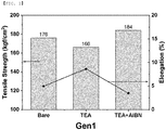
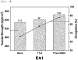
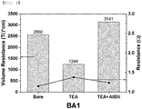
- Comparative Examples 1 and 2 were prepared by performing no treatment to the separators 1 and 2.
- Examples 1 and 2 were prepared by performing only TEA treatment to the separators 1 and 2 according to the present invention.
- Examples 3 and 4 were prepared by performing TEA and AIBN treatment to the separators 1 and 2. The tensile strength, the elongation, the insulation resistance, and the resistance of the separators of Comparative Examples 1 and 2, Examples 1 and 2, and Examples 3 and 4 were measured respectively with the following conditions.
- the insulation property (volume resistance) and mechanical strength of the separator after TEA treatment for forming crosslinking sites showed a decrease in Example 1 but were increased in Example 2. Moreover, the insulation property (volume resistance) and mechanical strength of the separator after AIBN solution treatment for forming crosslinking sites were increased in Examples 3 and 4. Particularly, it can be confirmed that the insulation property and mechanical strength are increased in all separators in the case of AIBN treatment. It can be seen that the method for improving the physical properties of a separator through post-treatment according to the present invention may be applied to the separator already produced as described above to improve the physical properties of the separator.
- Comparative Example 3 was prepared by coating a slurry on the separator 2 after the slurry was prepared by adding triethylamine (TEA), which is a material for forming crosslinking sites, and 2,2'-azobis(isobutyronitrile) (AIBN) for crosslinking in the slurry preparation process of the coating layer material.
- TAA triethylamine
- AIBN 2,2'-azobis(isobutyronitrile)
- Example 5 the insulation properties (volume resistance) and the mechanical strength of Example 5, in which TEA and AIBN treatment were performed after forming the coating layer, are increased as compared with Comparative Example 3, in which TEA and AIBN were added in the slurry preparation process of the coating layer. Consequently, it can be seen that the separator having the post-treatment crosslinking is superior to the separator performing crosslinking during the coating process.
Landscapes
- Chemical & Material Sciences (AREA)
- Chemical Kinetics & Catalysis (AREA)
- Health & Medical Sciences (AREA)
- Medicinal Chemistry (AREA)
- Polymers & Plastics (AREA)
- Organic Chemistry (AREA)
- General Chemical & Material Sciences (AREA)
- Electrochemistry (AREA)
- Engineering & Computer Science (AREA)
- Manufacturing & Machinery (AREA)
- Materials Engineering (AREA)
- Inorganic Chemistry (AREA)
- Composite Materials (AREA)
- Cell Separators (AREA)
Abstract
Description
- This application claims priority to and the benefit of Korean Patent Application No.
2018-0043356 filed on April 13, 2018 2019-0042803 filed on April 12, 2019 - The present invention relates to a method for improving physical properties of a separator by post-treatment crosslinking and a separator prepared thereby. Particularly, this invention relates to a method, which comprises forming crosslinkable sites on a binder molecule through post-treatment of a completed separator including an olefin substrate or no olefin substrate and crosslinking the crosslinkable sites to improve insulation properties and mechanical properties of the separator, and a separator having improved physical properties by the post-treatment crosslinking. The separator of the present invention may be used for batteries, and particularly for secondary batteries.
- With the recent trends toward reducing the weight and increasing the functionality of portable devices, such as smartphones, laptop computers, tablet PCs, and portable game machines, the demand for a secondary battery serving as a driving power source thereof is increasing. In the past, nickel-cadmium, nickel-hydrogen, and nickel-zinc batteries have been used, but lithium secondary batteries, which have high operating voltage and high energy density per unit weight, are most frequently used at present.
- In the case of lithium secondary batteries, the demand for lithium secondary batteries has increased with the growth of markets related to the portable device market. Lithium secondary batteries have also come to be used as the power sources for electric vehicles (EV) and hybrid electric vehicles (HEV).
- A lithium secondary battery is configured such that an electrode assembly having a positive electrode / separator / negative electrode structure, which can be charged and discharged, is mounted in a battery case. Each of the positive electrode and the negative electrode is manufactured by applying a slurry including an electrode active material to one surface or both surfaces of a metal current collector, drying the slurry, and rolling the metal current collector having the dried slurry applied thereto.
- The separator is one of the most important factors that affect the performance and the lifespan of a secondary battery. The separator should electrically isolate the positive electrode and the negative electrode from each other and should allow an electrolytic solution to pass smoothly through the separator. In addition, it is desirable for the separator to exhibit high mechanical strength and stability at high temperature.
- Various attempts have been made to increase insulation resistance and mechanical strength of the separator. In the case of a lithium ion battery, a low voltage phenomenon due to self-discharge is a problem, and a low insulation resistance of the separator is an important cause.
- United States Patent No.
8883354 discloses a microporous polymer layer comprising organically-modified aluminum boehmite particles and an organic polymer. However, there is a problem in that it shows a high defect rate in the process due to poor mechanical strength. - Korean Patent Application Publication No.
2016-0140211 - Korean Patent Application Publication No.
2012-0093772 - Journal of Power Sources 144(1):238-243, June 2005 discloses a crosslinking of PVdF-HFP/PEGDMA (polyethylene glycol dimethacrylate). However, this non-patent document does not disclose the application of the PVdF-HFP/PEGDMA to a separator but applies only to a polymer electrolyte.
- J Appl Electrochem 46: 69, 2016 discloses boehmite nanoparticles and a polyvinylidene fluoride polymer as separators for lithium secondary batteries. However, this non-patent document mentions that it is inadequate to apply to a battery cell assembly process, which has high stress.
- Journal of Membrane Science, 103, 2014 discloses a porous ceramic film based on magnesium aluminate as a separator for a lithium secondary battery having flexibility and thermal stability. However, this non-patent document does not disclose a method for improving the strength.
- RSC Adv., 6, 102762-102772, 2016 relates to a method for improving the physical properties of a forward osmosis separator and relates to a thin film composite (TFC) separator in which m-phenylene diamine (MPD) and trimesoyl chloride (TMC) are coupled with an electrospun PVDF support. The electrospun PVDF support was treated with triethyl amine (TEA) in order to increase the hydrophilicity and the like of the electrospun PVDF support.
- J. Appl. Polym. Sci. 8, 1415, 1964 discloses a crosslinking mechanism by post-treatment of a separator. Colloids and surfaces a:Physicochem. Eng. Aspects 297, 267, 2007 discloses the effect of improving the mechanical properties of a crosslinked separator. "Effect of crosslinking on the electrical properties of LDPE and its lightning impulse ageing characteristics," International Symposium on High Voltage Engineering", Hannover, Germany, 2011, August 22 discloses that the insulating properties of a crosslinked separator are improved.
- Meanwhile, a conventional method for improving the properties of a separator and the like has improved the physical properties of the separator by adding additional means or processes during the manufacturing process of the separator. However, a method for improving the physical properties of a separator through the post-treatment of a separator already manufactured has not yet been suggested.
- The present invention has been made in view of the above problems, and it is an object of the present invention to provide a method for improving physical properties of a separator, in which is capable of increasing insulation, tensile strength and elongation, and a separator having improved physical properties therethrough. Particularly, the present invention is characterized in that it is applied to a separator already manufactured.
- In a first aspect of the present invention, the above and other objects can be accomplished by the provision of a method for improving physical properties of a separator through post-treatment, comprising the steps of: a) preparing a separator having a layer comprising a binder on a substrate comprising a polyolefin substrate or no polyolefin substrate; b) transforming the binder into a crosslinkable coupling part by performing deintercalation of some elements of the binder; and c) treating the separator with a crosslinking initiator and/or a reaction catalyst after the treatment of the step b) .
- In addition to the crosslinking initiator in the step c), a crosslinking agent may be added at the same time.
- The separator having the coating layer comprising the binder on a substrate comprising the polyolefin substrate or no polyolefin substrate may have a coating layer comprising a binder on a polyolefin substrate. Alternatively, the separator may comprise no polyolefin substrate, and comprise inorganic particles and a binder for coupling between the inorganic particles.
- The inorganic particles may be high-dielectric inorganic particles having a dielectric constant of 1 or more, inorganic particles having piezoelectricity, inorganic particles having lithium ion transfer ability, alumina hydrate, or a mixture of two or more thereof.
- The examples of the binder include at least one selected from a group consisting of PVdF, TFE, and polyimide.
- Particularly, in the step b), deintercalation of some elements of the binder may be performed to transform a single bond into a double bond. Alternatively, in the step b), a solution comprising a basic substance or a substance including an amine group may be added to the separator. The basic substance or the substance including an amine group may be at least one selected from among alkali metal oxide, alkaline earth metal oxide, zeolite, limestone, sodium carbonate, ammonia, mono-alkyl amine, bi-alkyl amine, tri-alkyl amine, wherein the alkyl may contain 1 to 10 carbon atoms.
- As the crosslinking initiator, an azo-based compound or a peroxide-based compound may be used.
- The crosslinking agent may be selected from at least one of diaminoalkanes having 1 to 15 carbon atoms. Specific examples of the diaminoalkane may include 1,6-diaminohexane and 1,5-diaminopentane.
- A second aspect of the present invention provides a separator having improved physical properties by the method for improving the physical properties of the separator of the present invention.
- A third aspect of the present invention provides an electrochemical device comprising the separator having improved physical properties.
- The method for improving physical properties of a separator according to the present invention is advantageous in that it is capable of providing a separator with improved insulation and tensile strength compared with conventional separators. The present invention can be applied to a separator including a polyolefin substrate or no polyolefin substrate. In particular, while the conventional method is applied to a process for manufacturing a separator, the present invention provides an entirely different approach in that it improves the physical properties of a separator already manufactured. The present invention is advantageous in that it is not necessary to change the composition and process conditions of a conventional mass-production separator.
-
-
FIG. 1 is a graph showing the comparative measurement of tensile strength and elongation of a GEN 1 separator. -
FIG. 2 is a graph the comparative measurement of volume resistance and resistance of a GEN 1 separator. -
FIG. 3 is a graph showing the comparative measurement of tensile strength and elongation of a BA 1 separator. -
FIG. 4 is a graph showing the comparative measurement of volume resistance and resistance of a BA 1 separator. -
FIG. 5 is a graph showing the comparative measurement of tensile strength and elongation of a BA1 separator treated after coating and during coating. -
FIG. 6 is a graph showing the comparative measurement of volume resistance and resistance of a BA1 separator treated after coating and during coating. - Hereinafter, the present invention will be described in detail. It should be noted that terms or words used in this specification and the claims are not to be interpreted as having ordinary and dictionary-based meanings but as having meanings and concepts coinciding with the technical idea of the present invention based on the principle that the inventors may properly define the concepts of the terms in order to explain the invention in the best method. Consequently, the embodiments described in this specification are merely the most preferred embodiments and do not cover all technical ideas of the present invention, and therefore it should be understood that there may be various equivalents and modifications capable of substituting for the embodiments at the time of filing of the present application.
- In accordance with an aspect of the present invention, there is provided a method for improving physical properties of a separator by post-treatment, comprising the steps of: a) preparing a separator having a layer comprising a binder on a substrate including a polyolefin substrate or no polyolefin substrate; b) transforming the binder into a crosslinkable coupling part by performing deintercalation of some elements of the binder; and c) treating the separator with a crosslinking initiator and/or a reaction catalyst after the treatment of the step b).
- In the step b), crosslinking sites may be formed by performing deintercalation of some elements of the binder so as to transform a single bond into a double bond. The some elements may be H, F or Cl.
- In the step b), a solution containing a basic substance or a substance including an amine group may be added to the separator.
- In the step c), a crosslinking agent may be selectively added at the same time in addition to the crosslinking initiator.
- The step c) may comprise a step of coupling the crosslinking initiator to the coupling part, coupling between the binders at the coupling part, forming a separate crosslinking between the crosslinking initiators, coupling the crosslinking agent to the coupling part, or forming a separate crosslinking between the crosslinking agents.
- H, F, Cl and the like in binder polymers may be deintercalated to form a double bond so as to transform to a crosslinkable coupling part in the step b). Crosslinking may be formed by coupling between the crosslinking sites formed in the step b), the crosslinking initiator, the crosslinking agent and/or the reaction catalyst injected in the step c) may couple the crosslinking sites, or a separate crosslinking may be formed between the crosslinking initiator and the crosslinking agent.
- The separator having a layer comprising a binder on a substrate including a polyolefin substrate or no polyolefin substrate may be a separator having a coating layer comprising a binder on a polyolefin substrate, or a separator comprising no polyolefin substrate and comprising inorganic particles and a binder for coupling between the inorganic particles.
- The polyolefin substrate may be polyethylene, polypropylene, and the like as a polyolefin substrate used in a conventional separator. The technical details of the polyolefin substrate are well known to those of ordinary skill in the art, and a detailed description thereof will be omitted.
- In a structure including no polyolefin-based separator substrate, a conventional separator substrate is omitted, and a separator is made of materials constituting an inorganic layer. Since the separator includes no polyolefin separator substrate, the overall strength of the separator made solely of such an inorganic layer is low. Consequently, there is a problem that the separator interposed between electrode assemblies may be damaged, whereby a short circuit may occur. The method for improving the physical properties of a separator according to the present invention may be applied to the separator having no polyolefin-based separator substrate, which has already been completed, thereby increasing mechanical strength and insulation characteristics.
- The inorganic particles according to the present invention may form empty spaces among the inorganic particles, and thereby may form micro pores and maintain a physical shape as a spacer. The physical characteristics of the inorganic particles are not generally changed at a temperature of 200°C or more.
- The inorganic particles are not particularly restricted, as long as the inorganic particles are electrochemically stable. In other words, the inorganic particles that may be used in the present invention are not particularly restricted as long as the inorganic particles are not oxidized and/or reduced within the operating voltage range (e.g. 0 to 5 V based on Li/Li+) of a battery to which the inorganic particles are applied. Particularly, in the case in which inorganic particles having high electrolyte ion transfer ability are used, it is possible to improve the performance of an electrochemical device. Consequently, it is preferable for the electrolyte ion transfer ability of the inorganic particles to be as high as possible. In addition, in the case in which the inorganic particles have high density, it may be difficult to disperse the inorganic particles at the time of forming the porous separator, and the weight of a battery may increase at the time of manufacturing the battery. For these reasons, it is preferable for the density of the inorganic particles to be low. In addition, in the case in which the inorganic particles have high permittivity, the degree of dissociation of electrolyte salt, such as lithium salt, in a liquid electrolyte may increase, thereby improving the ion conductivity of the electrolytic solution.
- For the reasons described above, the inorganic particles may be high-dielectric inorganic particles having a dielectric constant of 1 or more, preferably 10 or more, inorganic particles having piezoelectricity, inorganic particles having lithium ion transfer ability, alumina hydrate, or a mixture of two or more thereof.
- Examples of the inorganic particles having a dielectric constant of 1 or more may include SrTiO3, SnO2, CeO2, MgO, NiO, CaO, ZnO, ZrO2, Y2O3, Al2O3, TiO2, SiC, or a mixture thereof. However, the present invention is not limited thereto.
- The inorganic particles having piezoelectricity are a material that is a nonconductor at normal pressure but, when a predetermined pressure is applied thereto, exhibits conductivity due to a change in the internal structure thereof. In the case in which the inorganic particles have a high dielectric value, e.g. a dielectric constant of 100 or more, and the inorganic particles are tensioned or compressed with a predetermined pressure, electric charges are generated. One face is charged as a positive pole and the other face is charged as a negative pole, whereby a potential difference is generated between the two faces.
- In the case in which inorganic particles having the above-mentioned characteristics are used, a short circuit may occur in both electrodes in the event of an external impact, such as local crushing or an impact with a nail. At this time, however, the positive electrode and the negative electrode may not directly contact each other due to the inorganic particles coated on the porous separator, and potential differences in particles may occur due to the piezoelectricity of the inorganic particles. Accordingly, electron migration, namely, fine current flow, is achieved between the two electrodes, whereby the voltage of the battery is gradually reduced, and therefore the stability of the battery may be improved.
- Examples of the inorganic particles having piezoelectricity may include BaTiO3, Pb(Zr,Ti)O3 (PZT), Pb1-xLaxZr1-yTiyO3 (PLZT), Pb(Mg1/3Nb2/3)O3-PbTiO3 (PMN-PT) hafnia (HfO2), and a mixture thereof. However, the present invention is not limited thereto.
- The inorganic particles having lithium ion transfer ability are inorganic particles that contain lithium elements and transport lithium ions without storing lithium. The inorganic particles having lithium ion transfer ability may transfer and transport lithium ions due to a kind of defect present in a particle structure. Consequently, lithium ionic conductivity in the battery may be improved, and therefore the battery performance may be improved.
- Examples of the inorganic particles having lithium ion transfer ability may include lithium phosphate (Li3PO4), lithium titanium phosphate (LixTiy(PO4)3, where 0<x<2 and 0<y<3), lithium aluminum titanium phosphate (LixAlyTiz(PO4)3, where 0<x<2, 0<y<1, and 0<z<3), (LiAlTiP)xOy-based glass (where 0<x<4 and 0<y<13) such as 14Li2O-9Al2O3-38TiO2-39P2O5, lithium lanthanum titanate (LixLayTiO3, where 0<x<2 and 0<y<3), lithium germanium thiophosphate (LixGeyPzSw, where 0<x<4, 0<y<1, 0<z<1, and 0<w<5) such as Li3.25Ge0.25P0.75S4, lithium nitride (LixNy, where 0<x<4 and 0<y<2) such as Li3N, SiS2-based glass (LixSiySz, where 0<x<3, 0<y<2, and 0<z<4) such as Li3PO4-Li2S-SiS2, P2S5-based glass (LixPySz, where 0<x<3, 0<y<3, and 0<z<7) such as LiI-Li2S-P2S5, and a mixture thereof. However, the present invention is not limited thereto.
- The alumina hydrate may be classified as crystalline alumina hydrate or gel-type alumina hydrate depending on the method of manufacturing the same. Examples of the crystalline alumina hydrate may include gibbsite ¡-Al(OH)3, bayerite Al(OH)3, diaspore ¡-AlOOH, and boehmite ¡-AlOOH, and the gel-type alumina hydrate may be aluminum hydroxide, which is prepared by depositing an aqueous solution containing aluminum ions using ammonia. Preferably, boehmite ¡-AlOOH may be used as the gel-type alumina hydrate.
- In the case in which the inorganic particles having high permittivity, the inorganic particles having piezoelectricity, the inorganic particles having lithium ion transfer ability, and the alumina hydrate are used together, the effects obtained through these ingredients may be further improved.
- The size of each of the inorganic particles is not particularly restricted. In order to form a film having a uniform thickness and to achieve appropriate porosity, however, each of the inorganic particles may have a size of 0.001 µm to 10 µm. In the case in which the size of each of the inorganic particles is less than 0.001 µm, dispersibility is reduced, whereby it is difficult to adjust the physical properties of the porous separator. In the case in which the size of each of the inorganic particles is greater than 10 µm, the thickness of a separator manufactured with the same content of a solid body is increased, whereby the mechanical properties of the separator are deteriorated. In addition, a short circuit may easily occur in the battery when the battery is charged and discharged due to excessively large-sized pores.
- The binder may also be commonly referred to as a polymer binder and may become a gel when the binder is impregnated with a liquid electrolytic solution, whereby the binder may have a characteristic of exhibiting high rate of electrolytic solution impregnation (degree of swelling). In fact, for the binder polymer having a high rate of electrolytic solution impregnation, an electrolytic solution injected after the assembly of a battery permeates into the polymer, and the polymer impregnated with the electrolytic solution exhibits electrolyte ion transfer ability. In addition, compared to a conventional hydrophobic polyolefin-based separator, wetting of the porous separator in the electrolytic solution may be improved, and it is possible to use polar electrolytic solutions for batteries, which has been difficult to use conventionally. Consequently, the binder may have a polymer with solubility parameter of 15 MPa1/2 to 45 MPa1/2, preferably 15 MPa1/2 to 25 MPa1/2 and 30 MPa1/2 to 45 MPa1/2. In the case in which the solubility parameter of the binder is less than 15 MPa1/2 and greater than 45 MPa1/2, it is difficult to impregnate the binder with a conventional electrolytic solution for batteries.
- Specifically, the binder may be at least one selected from the group consisting of polyvinylidene fluoride, polyvinylidene fluoride-hexafluoropropylene, polyvinylidene fluoride-trichloroethylene, polyvinylidene fluoride-chlorotrifluoroethylene, polymethyl methacrylate, polyacrylonitrile, polyvinyl pyrrolidone, polyvinyl acetate, ethylene vinyl acetate copolymer, polyethylene oxide, cellulose acetate, cellulose acetate butyrate, cellulose acetate propionate, cyanoethyl pullulan, cyanoethyl polyvinyl alcohol, cyanoethyl cellulose, cyanoethyl sucrose, pullulan, carboxymethyl cellulose, acrylonitrile butadiene styrene copolymer, ethylene-propylene-diene terpolymer (EPDM), sulfonated EPDM, styrene butadiene rubber (SBR), TFE, fluoro rubber, and polyimide. Preferably, the binder may be at least one selected from the group consisting of PVdF, TFE and polyimide.
- The basic substance or the substance having an amine group is at least one selected from the group among alkali metal oxide, alkaline earth metal oxide, zeolite, limestone, sodium carbonate, ammonia, mono-alkyl amine, bi-alkyl amine and tri-alkyl amine.
- The crosslinking initiator may be an azo-based compound or a peroxide-based compound. Specifically, the azo-based compound may be at least one selected from among 2,2'-azobis(2-methylbutyronitrile), 2,2'-azobis(isobutyronitrile), 2,2'-azobis(2,4-dimethylvaleronitrile), and 2,2'-azobis(4-methoxy-2,4-dimethylvaleronitrile). Preferably, the azo-based compound is 2,2'-azobis(isobutyronitrile)(AIBN).
- The peroxide-based compound may be at least one selected from among tetramethylbutyl peroxyneodecanoate, bis(4-butylcyclohexyl)peroxydicarbonate, di(2-ethylhexyl)peroxydicarbonate, butyl peroxyneodecanoate, dipropyl peroxydicarbonate, diisopropyl peroxydicarbonate, diethoxyethyl peroxydicarbonate, diethoxyhexyl peroxydicarbonate, hexyl peroxydicarbonate, dimethoxybutyl peroxydicarbonate, bis(3-methoxy-3-methoxybutyl)peroxydicarbonate, dibutyl peroxydicarbonate, dicetyl peroxydicarbonate, dimyristyl peroxydicarbonate, 1,1,3,3-tetramethylbutyl peroxypivalate, hexyl peroxypivalate, butyl peroxypivalate, trimethylhexanoyl peroxide, dimethylhydroxybutyl peroxyneodecanoate, amyl peroxyneodecanoate, Atofina, butyl peroxyneodecanoate, t-butyl peroxyneoheptanoate, amyl peroxypivalate, t-butyl peroxypivalate, t-amyl peroxy-2-ethylhexanoate, lauroyl peroxide, dilauroyl peroxide, didecanoyl peroxide, benzoyl peroxide, and dibenzoyl peroxide.
- The amount of the crosslinking initiator, the crosslinking agent, and/or the reaction catalyst may be greater than 0 wt% and equal to or less than 5 wt%, preferably greater than 0.2 wt% and equal to or less than 5 wt%, more preferably greater than 0.5 wt% and equal to or less than 5 wt%, and most preferably greater than 1 wt% and equal to or less than 2 wt% based on a total weight of a solid body in the separator.
- In the case in which the amount of the crosslinking initiator, the crosslinking agent and/or the reaction catalyst in the separator is lower than the lower limit, the crosslinking may not be completely performed.
- In the present invention, the crosslinking initiator may react at a specific temperature to have the crosslinking agent form a crosslinked structure. As the density of the separator of the present invention increases due to the characteristics of the crosslinked structure, physical properties related to rigidity of the separator may be improved. Consequently, as the migration of electrons is affected, the insulation resistance may be increased.
- The reaction temperature of the crosslinking initiator may be 40 °C to 150 °C, preferably 50 °C to 130 °C. The reaction rate of the crosslinking initiator is slow at temperatures lower than the above reaction temperature range. The crosslinking initiator reacts when the reaction temperature of the crosslinking initiator reaches the above reaction temperature range, whereby a three-dimensional net-shaped structure is formed through crosslinking.
- In the case in which the reaction temperature of the crosslinking initiator is lower than 40 °C, it is difficult for the crosslinking initiator to perform a crosslinking reaction, which is undesirable. In the case in which the reaction temperature of the crosslinking initiator is higher than 150 °C, the conventional separator may be deformed or may melt, which is also undesirable.
- The crosslinking agent may be selected from at least one of diaminoalkanes having 1 to 15 carbon atoms. Particularly, the crosslinking agent may be selected from at least one of 1,6-diaminohexane or 1,5-diaminopentane.
- The present invention also provides an electrochemical device including a positive electrode, a negative electrode, the separator interposed between the positive electrode and the negative electrode, and an electrolyte. Here, the electrochemical device may be a lithium secondary battery.
- The positive electrode may be manufactured by applying a mixture of a positive electrode active material, a conductive agent, and a binder to a positive electrode current collector and drying the mixture. A filler may be further added to the mixture as needed.
- In general, the positive electrode current collector is manufactured so as to have a thickness of 3 µm to 500 µm. The positive electrode current collector is not particularly restricted, as long as the positive electrode current collector exhibits high conductivity while the positive electrode current collector does not induce any chemical change in a battery to which the positive electrode current collector is applied. For example, the positive electrode current collector may be made of stainless steel, aluminum, nickel, titanium, or plastic carbon. Alternatively, the positive electrode current collector may be made of aluminum or stainless steel, the surface of which is treated with carbon, nickel, titanium, or silver. In addition, the positive electrode current collector may have a micro-scale uneven pattern formed on the surface thereof so as to increase the force of adhesion of the positive electrode active material. The positive electrode current collector may be configured in various forms, such as those of a film, a sheet, a foil, a net, a porous body, a foam body, and a non-woven fabric body.
- The positive electrode active material may be, but is not limited to, a layered compound, such as a lithium cobalt oxide (LiCoO2) or a lithium nickel oxide (LiNiO2), or a compound substituted with one or more transition metals; a lithium manganese oxide represented by the chemical formula Li1+xMn2-xO4 (where x = 0 to 0.33) or a lithium manganese oxide, such as LiMnO3, LiMn2O3, or LiMnO2; a lithium copper oxide (Li2CuO2) ; a vanadium oxide, such as LiV3O8, V2O5, or Cu2V2O7; an Ni-sited lithium nickel oxide represented by the chemical formula LiNi1-xMxO2 (where M= Co, Mn, Al, Cu, Fe, Mg, B, or Ga, and x = 0.01 to 0.3); a lithium manganese composite oxide represented by the chemical formula LiMn2-xMxO2 (where M= Co, Ni, Fe, Cr, Zn, or Ta, and x = 0.01 to 0.1) or the chemical formula Li2Mn3MO8 (where M= Fe, Co, Ni, Cu, or Zn) ; LiMn2O4 having Li of a chemical formula partially replaced by alkaline earth metal ions; a disulfide compound; or Fe2(MoO4)3.
- The conductive agent is generally added in an amount of 1 to 30 wt% based on the total weight of the compound including the positive electrode active material. The conductive agent is not particularly restricted, as long as the conductive agent exhibits high conductivity without inducing any chemical change in a battery to which the conductive agent is applied. For example, graphite, such as natural graphite or artificial graphite; carbon black, such as carbon black, acetylene black, Ketjen black, channel black, furnace black, lamp black, or summer black; conductive fiber, such as carbon fiber or metallic fiber; metallic powder, such as carbon fluoride powder, aluminum powder, or nickel powder; conductive whisker, such as a zinc oxide or potassium titanate; a conductive metal oxide, such as a titanium oxide; or conductive materials, such as polyphenylene derivatives, may be used as the conductive agent.
- The binder is a component assisting in binding between the active material and the conductive agent and in binding with the current collector. The binder is generally added in an amount of 1 to 30 wt% based on the total weight of the compound including the positive electrode active material. As examples of the binder, there may be used polyvinylidene fluoride, polyvinyl alcohol, carboxymethylcellulose (CMC), starch, hydroxypropylcellulose, regenerated cellulose, polyvinyl pyrrolidone, tetrafluoroethylene, polyethylene, polypropylene, ethylene-propylene-diene terpolymer (EPDM), sulfonated EPDM, styrene butadiene rubber, fluoro rubber, and various copolymers.
- The filler is an optional component used to inhibit expansion of the positive electrode. There is no particular limit to the filler, as long as it does not cause chemical changes in a battery to which the filler is applied and is made of a fibrous material. As examples of the filler, there may be used olefin polymers, such as polyethylene and polypropylene; and fibrous materials, such as glass fiber and carbon fiber.
- The negative electrode may be manufactured by applying a negative electrode material to a negative electrode current collector and drying the same. The above-described components may be selectively further included as needed.
- In general, the negative electrode current collector is manufactured so as to have a thickness of 3 µm to 500 µm. The negative electrode current collector is not particularly restricted, as long as the negative electrode current collector exhibits high conductivity while the negative electrode current collector does not induce any chemical change in a battery to which the negative electrode current collector is applied. For example, the negative electrode current collector may be made of copper, stainless steel, aluminum, nickel, titanium, or plastic carbon. Alternatively, the negative electrode current collector may be made of copper or stainless steel, the surface of which is treated with carbon, nickel, titanium, or silver, or an aluminum-cadmium alloy. In addition, the negative electrode current collector may have a micro-scale uneven pattern formed on the surface thereof so as to increase the force of adhesion of the negative electrode active material, in the same manner as the positive electrode current collector. The negative electrode current collector may be configured in various forms, such as those of a film, a sheet, a foil, a net, a porous body, a foam body, and a non-woven fabric body.
- As the negative electrode active material, for example, there may be used carbon, such as a hard carbon or a graphite-based carbon; a metal composite oxide, such as LixFe2O3 (0≤x≤1), LixWO2 (0≤x≤1), SnxMe1-xMe'yOz (Me: Mn, Fe, Pb, Ge; Me': Al, B, P, Si,
Group 1, 2 and 3 elements of the periodic table, halogen; 0<x≤1; 1≤y≤3; 1≤z≤8); lithium metal; lithium alloy; silicon-based alloy; tin-based alloy; a metal oxide, such as SnO, SnO2, PbO, PbO2, Pb2O3, Pb3O4, Sb2O3, Sb2O4, Sb2O5, GeO, GeO2, Bi2O3, Bi2O4, or Bi2O5; a conductive polymer, such as polyacetylene; or a Li-Co-Ni based material. - In accordance with another aspect of the present invention, there is provided a battery pack including the electrochemical device.
- Specifically, the battery pack may be used as a power source for a device requiring the ability to withstand high temperatures, a long lifespan, high rate characteristics, etc. Specific examples of the device may include a mobile electronic device, a wearable electronic device, a power tool driven by a battery-powered motor; an electric automobile, such as an electric vehicle (EV), a hybrid electric vehicle (HEV), or a plug-in hybrid electric vehicle (PHEV); an electric two-wheeled vehicle, such as an electric bicycle (E-bike) or an electric scooter (E-scooter); an electric golf cart; and a power storage system. However, the present invention is not limited thereto.
- The structure and manufacturing method of the device are well known in the art to which the present invention pertains, and a detailed description thereof will be omitted.
- Hereinafter, the present invention will be described in detail with reference to the following Examples and Experimental Example; however, the present invention is not limited by the Examples and the Experimental Example. The Examples may be modified into various other forms, and the scope of the present invention should not be interpreted as being limited by the Examples, which will be described in detail. The Examples are provided in order to more completely explain the prevent invention to a person who has average knowledge in the art to which the present invention pertains.
- For the purpose of experiments, two kinds of separators, CSP gen1 (separator 1), and BA1_B09PA1 (separator 2), which were already produced, were used. The CSP gen1 separator is made only of aluminum oxide Al2O3 particles and PVDF binder. The BA1_B09PA1 separator has a coating layer comprising Al2O3 inorganic particles and PVDF binder on a polyethylene substrate.
- Triethylamine (TEA) was used as a material for forming crosslinking sites. After each of the separators was cut to a size of 10 cm x 10 cm, the separators were immersed in 99 % TEA solution at ambient temperature for 5 minutes, and then the separators were taken out and dried in a fume hood.
- In order to have crosslinking, the separators having crosslinking sites were immersed in a solution in which 1.5 wt% of 2,2'-azobis(isobutyronitrile)(AIBN) was dissolved in an ethanol solvent and were treated at 60 °C for 30 minutes. The separators were then washed with ethanol and dried in a fume hood.
- Comparative Examples 1 and 2 were prepared by performing no treatment to the
separators 1 and 2. Examples 1 and 2 were prepared by performing only TEA treatment to theseparators 1 and 2 according to the present invention. Examples 3 and 4 were prepared by performing TEA and AIBN treatment to theseparators 1 and 2. The tensile strength, the elongation, the insulation resistance, and the resistance of the separators of Comparative Examples 1 and 2, Examples 1 and 2, and Examples 3 and 4 were measured respectively with the following conditions. -
- Applied voltage: 100V
- Measurement time: 3S
- Size and shape of electrode: 19.6 cm2 circular
- <Measurement condition of tensile strength>
- Width of separator: 2 cm
- Tensile speed: 500 mm/min
-
FIGS. 1 to 4 show the measurement results of physical properties of Comparative Examples 1 and 2, and Examples 1, 2, 3 and 4 according to the present invention, respectively. In the Gen1 separator, Bare is Comparative Example 1 having no treatment applied, TEA is Example 1, and TEA+AIBN is Example 3. In the BA1 separator, Bare is Comparative Example 2 having no treatment applied, TEA is Example 2, and TEA+AIBN is Example 4. - The insulation property (volume resistance) and mechanical strength of the separator after TEA treatment for forming crosslinking sites showed a decrease in Example 1 but were increased in Example 2. Moreover, the insulation property (volume resistance) and mechanical strength of the separator after AIBN solution treatment for forming crosslinking sites were increased in Examples 3 and 4. Particularly, it can be confirmed that the insulation property and mechanical strength are increased in all separators in the case of AIBN treatment. It can be seen that the method for improving the physical properties of a separator through post-treatment according to the present invention may be applied to the separator already produced as described above to improve the physical properties of the separator.
- Before forming the coating layer made of Al2O3 inorganic particles and PVDF binder on the
separator 2, Comparative Example 3 was prepared by coating a slurry on theseparator 2 after the slurry was prepared by adding triethylamine (TEA), which is a material for forming crosslinking sites, and 2,2'-azobis(isobutyronitrile) (AIBN) for crosslinking in the slurry preparation process of the coating layer material. The tensile strength, the elongation, the insulation resistance, and the resistance of the separators of Comparative Example 3 and Example 4, which performed triethylamine (TEA) and 2,2'-azobis(isobutyronitrile) (AIBN) treatment to theseparator 2 according to the present invention, were measured respectively with the following conditions. -
- Applied voltage: 100V
- Measurement time: 3S
- Size and shape of electrode: 19.6 cm2 circular
- <Measurement condition of tensile strength>
- Width of separator: 1.5 cm
- Tensile speed: 500 mm/min
-
FIGS. 5 and6 show the measurement results of physical properties of Comparative Example 3 (In Coating) and Example 4 (After Coating) according to the present invention, respectively. Crosslinking during the process in the BA1 separator is Comparative Example 3 in which TEA and AIBN were added in the slurry preparation process of the coating layer. Post-treatment crosslinking in the BA1 separator is Example 4 in which TEA and AIBN treatment were performed after forming the coating layer. - It can be confirmed that the insulation properties (volume resistance) and the mechanical strength of Example 5, in which TEA and AIBN treatment were performed after forming the coating layer, are increased as compared with Comparative Example 3, in which TEA and AIBN were added in the slurry preparation process of the coating layer. Consequently, it can be seen that the separator having the post-treatment crosslinking is superior to the separator performing crosslinking during the coating process.
Claims (22)
- A method for improving physical properties of a separator by post-treatment, comprising the steps of:a) preparing a separator having a layer comprising a binder on a substrate comprising a polyolefin substrate or no polyolefin substrate;b) transforming the binder into a crosslinkable coupling part by performing deintercalation of some elements of the binder; andc) treating the separator with a crosslinking initiator and/or a reaction catalyst after the treatment of the step b) .
- The method according to claim 1,
wherein a crosslinking agent is selectively added at the same time in addition to the crosslinking initiator in the step c). - The method according to claim 1,
wherein the separator has a coating layer comprising a binder on a polyolefin substrate, or
wherein the separator comprises no polyolefin substrate, and comprises inorganic particles, and a binder for coupling between the inorganic particles. - The method according to claim 3,
wherein the inorganic particles are high-dielectric inorganic particles having a dielectric constant of 1 or more, inorganic particles having piezoelectricity, inorganic particles having lithium ion transfer ability, alumina hydrate, or a mixture of two or more thereof. - The method according to claim 3,
wherein the inorganic particles are at least one selected from a group consisting of Al2O3, AlOOH, SiO2, MgO, TiO2 and BaTiO2. - The method according to claim 3,
wherein the binder is at least one selected from a group consisting of polyvinylidene fluoride (PVdF), polyvinylidene fluoride-hexafluoropropylene, polyvinylidene fluoride-trichloroethylene, polyvinylidene fluoride-chlorotrifluoroethylene, polymethyl methacrylate, polyacrylonitrile, polyvinyl pyrrolidone, polyvinyl acetate, ethylene vinyl acetate copolymer, polyethylene oxide, cellulose acetate, cellulose acetate butyrate, cellulose acetate propionate, cyanoethyl pullulan, cyanoethyl polyvinyl alcohol, cyanoethyl cellulose, cyanoethyl sucrose, pullulan, carboxymethyl cellulose, acrylonitrile butadiene styrene copolymer, ethylene-propylene-diene terpolymer (EPDM), sulfonated EPDM, styrene butadiene rubber (SBR), tetrafluoroethylene (TFE), fluoro rubber, and polyimide. - The method according to claim 6,
wherein the binder is at least one selected from a group consisting of PVdF, TFE, and polyimide. - The method according to claim 1,
wherein in the step b), crosslinking sites are formed by performing deintercalation of some elements of the binder so as to transform a single bond into a double bond. - The method according to claim 8,
wherein the some elements are H, F or Cl. - The method according to claim 1,
wherein in the step b), a solution comprising a basic substance or a substance having an amine group is added to the separator. - The method according to claim 10,
wherein the basic substance or the substance having an amine group is at least one selected from among alkali metal oxide, alkaline earth metal oxide, zeolite, limestone, sodium carbonate, ammonia, mono-alkyl amine, bi-alkyl amine, and tri-alkyl amine, and the alkyl contains 1 to 10 carbon atoms. - The method according to claim 2,
wherein the step c) comprises a step of coupling the crosslinking initiator to the coupling part, coupling between the binders at the coupling part, forming a separate crosslinking between the crosslinking initiators, coupling the crosslinking agent to the coupling part, or forming a separate crosslinking between the crosslinking agents. - The method according to claim 1,
wherein the crosslinking initiator is an azo-based compound or a peroxide-based compound. - The method according to claim 13,
wherein the azo-based compound is at least one selected from among 2,2'-azobis(2-methylbutyronitrile), 2,2'-azobis(isobutyronitrile), 2,2'-azobis(2,4-dimethylvaleronitrile), and 2,2'-azobis(4-methoxy-2,4-dimethylvaleronitrile). - The method according to claim 13,
wherein the peroxide-based compound is at least one selected from among tetramethylbutyl peroxyneodecanoate, bis(4-butylcyclohexyl)peroxydicarbonate, di(2-ethylhexyl)peroxydicarbonate, butyl peroxyneodecanoate, dipropyl peroxydicarbonate, diisopropyl peroxydicarbonate, diethoxyethyl peroxydicarbonate, diethoxyhexyl peroxydicarbonate, hexyl peroxydicarbonate, dimethoxybutyl peroxydicarbonate, bis(3-methoxy-3-methoxybutyl)peroxydicarbonate, dibutyl peroxydicarbonate, dicetyl peroxydicarbonate, dimyristyl peroxydicarbonate, 1,1,3,3-tetramethylbutyl peroxypivalate, hexyl peroxypivalate, butyl peroxypivalate, trimethylhexanoyl peroxide, dimethylhydroxybutyl peroxyneodecanoate, amyl peroxyneodecanoate, Atofina, butyl peroxyneodecanoate, t-butyl peroxyneoheptanoate, amyl peroxypivalate, t-butyl peroxypivalate, t-amyl peroxy-2-ethylhexanoate, lauroyl peroxide, dilauroyl peroxide, didecanoyl peroxide, benzoyl peroxide, or dibenzoyl peroxide. - The method according to claim 2,
wherein the crosslinking agent is selected from at least one of diaminoalkanes having 1 to 15 carbon atoms. - The method according to claim 16,
wherein the crosslinking agent is selected from at least one of 1,6-diaminohexane or 1,5-diaminopentane. - The method according to claim 2,
wherein a temperature of treating the crosslinking initiator, the crosslinking agent, and/or the reaction catalyst is 40 °C to 150°C. - The method according to claim 2,
wherein an amount of the crosslinking initiator, the crosslinking agent, and/or the reaction catalyst is greater than 0 wt% and equal to or less than 5 wt% based on a total weight of a solid body in the separator. - A separator having improved physical properties obtained by the method according to any one of claims 1 to 19.
- The separator for an electrochemical device according to claim 20,
wherein the separator has an air permeability of 50sec/100cc to 4,000sec/100cc. - An electrochemical device comprising the separator according to claim 20.
Applications Claiming Priority (3)
| Application Number | Priority Date | Filing Date | Title |
|---|---|---|---|
| KR20180043356 | 2018-04-13 | ||
| KR1020190042803A KR102314366B1 (en) | 2018-04-13 | 2019-04-12 | Method of Improving Properties of Separator by Post Cross-linking and The Separator Produced Thereby |
| PCT/KR2019/004477 WO2019199137A1 (en) | 2018-04-13 | 2019-04-13 | Method for improving properties of separator through post-treatment crosslinking and separator thereby |
Publications (2)
| Publication Number | Publication Date |
|---|---|
| EP3663337A1 true EP3663337A1 (en) | 2020-06-10 |
| EP3663337A4 EP3663337A4 (en) | 2020-12-09 |
Family
ID=68461184
Family Applications (1)
| Application Number | Title | Priority Date | Filing Date |
|---|---|---|---|
| EP19785657.8A Pending EP3663337A4 (en) | 2018-04-13 | 2019-04-13 | Method for improving properties of separator through post-treatment crosslinking and separator thereby |
Country Status (3)
| Country | Link |
|---|---|
| US (1) | US20200287187A1 (en) |
| EP (1) | EP3663337A4 (en) |
| KR (1) | KR102314366B1 (en) |
Families Citing this family (1)
| Publication number | Priority date | Publication date | Assignee | Title |
|---|---|---|---|---|
| KR102571758B1 (en) * | 2022-12-14 | 2023-08-28 | 주식회사 오상엠엔이티 | Surge Response Based Voltage Resistant CCTV Video Detection System |
Family Cites Families (19)
| Publication number | Priority date | Publication date | Assignee | Title |
|---|---|---|---|---|
| TW222650B (en) * | 1991-04-01 | 1994-04-21 | Dow Corning | |
| WO1996003202A1 (en) * | 1994-07-28 | 1996-02-08 | Millipore Corporation | Porous composite membrane and process |
| US6077624A (en) * | 1997-08-14 | 2000-06-20 | Valence Technology, Inc. | Lithium ion cells with improved thermal stability |
| AU5338899A (en) * | 1998-09-08 | 2000-03-27 | Dyneon Llc | Multilayer composites |
| EP1054023A1 (en) * | 1999-05-21 | 2000-11-22 | Atofina | Process for chemical modification of fluorinated polymers, electrodes for lithium-ion batteries, and coatings for metal substrates containing these modified polymers |
| FR2807212A1 (en) * | 2000-03-31 | 2001-10-05 | Atofina | STRUCTURE COMPRISING A FLUORINE PRIMER AND ELECTRODE BASED ON SAID STRUCTURE |
| EP1773477B1 (en) * | 2004-07-05 | 2011-09-07 | Siemens Water Technologies Corp. | Hydrophilic membranes |
| US8883354B2 (en) | 2006-02-15 | 2014-11-11 | Optodot Corporation | Separators for electrochemical cells |
| KR101002161B1 (en) * | 2007-11-29 | 2010-12-17 | 주식회사 엘지화학 | A separator having porous coating layer, manufacturing mehtod thereof and electrochemical device containing the same |
| CN101485960B (en) * | 2009-01-09 | 2011-08-17 | 清华大学 | Method for modifying interpenetrating polymer network on surface of polyvinylidene fluoride porous membrane |
| US8796384B2 (en) * | 2009-07-03 | 2014-08-05 | Daikin Industries, Ltd. | Crosslinkable fluorine rubber composition, fluorine rubber molded article, and method for producing the same |
| KR101254693B1 (en) | 2011-02-15 | 2013-04-15 | 주식회사 엘지화학 | A separator, the manufacturing method thereof, and electrochemical device containing the same |
| KR101723994B1 (en) * | 2014-02-21 | 2017-04-06 | 주식회사 포스코 | Separator, method of manufacturing the same, lithium polymer secondary battery including the same, and method of manufacturing lithium polymer secondary battery using the same |
| KR101630208B1 (en) * | 2014-08-20 | 2016-06-14 | 한국화학연구원 | A preparation method of hydrophilic membrane and a hydrophilic membrane prepared by the same |
| CN105363357B (en) * | 2014-09-02 | 2018-08-21 | 中国石油化工集团公司 | It is a kind of using bifunctional vinyl compound as polyvinyl alcohol film of crosslinking agent and preparation method thereof |
| KR102466670B1 (en) | 2015-05-29 | 2022-11-14 | 삼성전자주식회사 | Electrolyte for lithium battery, and negative electrode and lithium battery including the same |
| KR101995374B1 (en) * | 2015-12-24 | 2019-07-03 | 주식회사 엘지화학 | Binder suspension composition, method for preparing electrode for secondary battery using the same, and electrode for secondary battery prepared thereby |
| WO2019088698A2 (en) * | 2017-10-31 | 2019-05-09 | 주식회사 엘지화학 | Separator without separator substrate and electrochemical device comprising same |
| KR20190049581A (en) * | 2017-10-31 | 2019-05-09 | 주식회사 엘지화학 | Separator without separator base member and electrochemical device comprising thereof |
-
2019
- 2019-04-12 KR KR1020190042803A patent/KR102314366B1/en active IP Right Grant
- 2019-04-13 EP EP19785657.8A patent/EP3663337A4/en active Pending
- 2019-04-13 US US16/646,595 patent/US20200287187A1/en active Pending
Also Published As
| Publication number | Publication date |
|---|---|
| KR102314366B1 (en) | 2021-10-20 |
| KR20190120081A (en) | 2019-10-23 |
| EP3663337A4 (en) | 2020-12-09 |
| US20200287187A1 (en) | 2020-09-10 |
Similar Documents
| Publication | Publication Date | Title |
|---|---|---|
| US11398660B2 (en) | Flame retardant separator having asymmetric structure for secondary batteries | |
| US11990641B2 (en) | Separator having no separator substrate and electrochemical device including the same | |
| US11757155B2 (en) | Separator for secondary batteries having no separator substrate | |
| CN110301056B (en) | Battery separator including hydrofluoric acid reducing material | |
| EP3663337A1 (en) | Method for improving properties of separator through post-treatment crosslinking and separator thereby | |
| KR20140014493A (en) | Fabricating method of seperator and electrochemical cell having the same | |
| US11929520B2 (en) | Porous separator without polyolefin substrate including inorganic particles and polymer binder | |
| CN110914346B (en) | Method for improving physical properties of separator by post-treatment crosslinking and separator prepared thereby | |
| JP2013026165A (en) | Separator for nonaqueous electrolyte battery, and nonaqueous electrolyte battery | |
| EP4053235A1 (en) | Electrode inorganic layer coating tape and manufacturing method therefor | |
| CN116134674A (en) | Electrode assembly including separator having conductive layer formed thereon and battery cell including the same | |
| CN116868434A (en) | Separator for secondary battery | |
| CN117426007A (en) | Method for manufacturing separator for lithium secondary battery, separator for lithium secondary battery manufactured by using same, and lithium secondary battery having same |
Legal Events
| Date | Code | Title | Description |
|---|---|---|---|
| STAA | Information on the status of an ep patent application or granted ep patent |
Free format text: STATUS: THE INTERNATIONAL PUBLICATION HAS BEEN MADE |
|
| PUAI | Public reference made under article 153(3) epc to a published international application that has entered the european phase |
Free format text: ORIGINAL CODE: 0009012 |
|
| STAA | Information on the status of an ep patent application or granted ep patent |
Free format text: STATUS: REQUEST FOR EXAMINATION WAS MADE |
|
| 17P | Request for examination filed |
Effective date: 20200306 |
|
| AK | Designated contracting states |
Kind code of ref document: A1 Designated state(s): AL AT BE BG CH CY CZ DE DK EE ES FI FR GB GR HR HU IE IS IT LI LT LU LV MC MK MT NL NO PL PT RO RS SE SI SK SM TR |
|
| AX | Request for extension of the european patent |
Extension state: BA ME |
|
| A4 | Supplementary search report drawn up and despatched |
Effective date: 20201109 |
|
| RIC1 | Information provided on ipc code assigned before grant |
Ipc: H01M 2/16 20060101ALI20201103BHEP Ipc: C08J 5/22 20060101AFI20201103BHEP Ipc: C08K 5/00 20060101ALI20201103BHEP Ipc: C08K 5/23 20060101ALI20201103BHEP Ipc: C08K 5/17 20060101ALI20201103BHEP Ipc: H01M 2/14 20060101ALI20201103BHEP Ipc: C08K 5/14 20060101ALI20201103BHEP |
|
| DAV | Request for validation of the european patent (deleted) | ||
| DAX | Request for extension of the european patent (deleted) | ||
| RAP1 | Party data changed (applicant data changed or rights of an application transferred) |
Owner name: LG ENERGY SOLUTION LTD. |
|
| RAP3 | Party data changed (applicant data changed or rights of an application transferred) |
Owner name: LG ENERGY SOLUTION, LTD. |
|
| STAA | Information on the status of an ep patent application or granted ep patent |
Free format text: STATUS: EXAMINATION IS IN PROGRESS |
|
| 17Q | First examination report despatched |
Effective date: 20231218 |