EP3663266B1 - Water purifier and control method of the same - Google Patents
Water purifier and control method of the same Download PDFInfo
- Publication number
- EP3663266B1 EP3663266B1 EP19213617.4A EP19213617A EP3663266B1 EP 3663266 B1 EP3663266 B1 EP 3663266B1 EP 19213617 A EP19213617 A EP 19213617A EP 3663266 B1 EP3663266 B1 EP 3663266B1
- Authority
- EP
- European Patent Office
- Prior art keywords
- water
- filter
- quality value
- supplied
- purifier
- Prior art date
- Legal status (The legal status is an assumption and is not a legal conclusion. Google has not performed a legal analysis and makes no representation as to the accuracy of the status listed.)
- Active
Links
Images


Classifications
-
- C—CHEMISTRY; METALLURGY
- C02—TREATMENT OF WATER, WASTE WATER, SEWAGE, OR SLUDGE
- C02F—TREATMENT OF WATER, WASTE WATER, SEWAGE, OR SLUDGE
- C02F1/00—Treatment of water, waste water, or sewage
- C02F1/008—Control or steering systems not provided for elsewhere in subclass C02F
-
- B—PERFORMING OPERATIONS; TRANSPORTING
- B67—OPENING, CLOSING OR CLEANING BOTTLES, JARS OR SIMILAR CONTAINERS; LIQUID HANDLING
- B67D—DISPENSING, DELIVERING OR TRANSFERRING LIQUIDS, NOT OTHERWISE PROVIDED FOR
- B67D1/00—Apparatus or devices for dispensing beverages on draught
- B67D1/08—Details
- B67D1/12—Flow or pressure control devices or systems, e.g. valves, gas pressure control, level control in storage containers
- B67D1/1277—Flow control valves
-
- B—PERFORMING OPERATIONS; TRANSPORTING
- B01—PHYSICAL OR CHEMICAL PROCESSES OR APPARATUS IN GENERAL
- B01D—SEPARATION
- B01D35/00—Filtering devices having features not specifically covered by groups B01D24/00 - B01D33/00, or for applications not specifically covered by groups B01D24/00 - B01D33/00; Auxiliary devices for filtration; Filter housing constructions
- B01D35/14—Safety devices specially adapted for filtration; Devices for indicating clogging
- B01D35/157—Flow control valves: Damping or calibrated passages
- B01D35/1573—Flow control valves
-
- B—PERFORMING OPERATIONS; TRANSPORTING
- B01—PHYSICAL OR CHEMICAL PROCESSES OR APPARATUS IN GENERAL
- B01D—SEPARATION
- B01D61/00—Processes of separation using semi-permeable membranes, e.g. dialysis, osmosis or ultrafiltration; Apparatus, accessories or auxiliary operations specially adapted therefor
- B01D61/02—Reverse osmosis; Hyperfiltration ; Nanofiltration
- B01D61/025—Reverse osmosis; Hyperfiltration
-
- B—PERFORMING OPERATIONS; TRANSPORTING
- B01—PHYSICAL OR CHEMICAL PROCESSES OR APPARATUS IN GENERAL
- B01D—SEPARATION
- B01D61/00—Processes of separation using semi-permeable membranes, e.g. dialysis, osmosis or ultrafiltration; Apparatus, accessories or auxiliary operations specially adapted therefor
- B01D61/02—Reverse osmosis; Hyperfiltration ; Nanofiltration
- B01D61/12—Controlling or regulating
-
- B—PERFORMING OPERATIONS; TRANSPORTING
- B67—OPENING, CLOSING OR CLEANING BOTTLES, JARS OR SIMILAR CONTAINERS; LIQUID HANDLING
- B67D—DISPENSING, DELIVERING OR TRANSFERRING LIQUIDS, NOT OTHERWISE PROVIDED FOR
- B67D1/00—Apparatus or devices for dispensing beverages on draught
- B67D1/0003—Apparatus or devices for dispensing beverages on draught the beverage being a single liquid
- B67D1/0014—Apparatus or devices for dispensing beverages on draught the beverage being a single liquid the beverage being supplied from water mains
-
- C—CHEMISTRY; METALLURGY
- C02—TREATMENT OF WATER, WASTE WATER, SEWAGE, OR SLUDGE
- C02F—TREATMENT OF WATER, WASTE WATER, SEWAGE, OR SLUDGE
- C02F1/00—Treatment of water, waste water, or sewage
- C02F1/001—Processes for the treatment of water whereby the filtration technique is of importance
-
- G—PHYSICS
- G01—MEASURING; TESTING
- G01N—INVESTIGATING OR ANALYSING MATERIALS BY DETERMINING THEIR CHEMICAL OR PHYSICAL PROPERTIES
- G01N27/00—Investigating or analysing materials by the use of electric, electrochemical, or magnetic means
- G01N27/02—Investigating or analysing materials by the use of electric, electrochemical, or magnetic means by investigating impedance
- G01N27/04—Investigating or analysing materials by the use of electric, electrochemical, or magnetic means by investigating impedance by investigating resistance
- G01N27/06—Investigating or analysing materials by the use of electric, electrochemical, or magnetic means by investigating impedance by investigating resistance of a liquid
-
- B—PERFORMING OPERATIONS; TRANSPORTING
- B01—PHYSICAL OR CHEMICAL PROCESSES OR APPARATUS IN GENERAL
- B01D—SEPARATION
- B01D2311/00—Details relating to membrane separation process operations and control
- B01D2311/04—Specific process operations in the feed stream; Feed pretreatment
-
- B—PERFORMING OPERATIONS; TRANSPORTING
- B67—OPENING, CLOSING OR CLEANING BOTTLES, JARS OR SIMILAR CONTAINERS; LIQUID HANDLING
- B67D—DISPENSING, DELIVERING OR TRANSFERRING LIQUIDS, NOT OTHERWISE PROVIDED FOR
- B67D2210/00—Indexing scheme relating to aspects and details of apparatus or devices for dispensing beverages on draught or for controlling flow of liquids under gravity from storage containers for dispensing purposes
- B67D2210/00002—Purifying means
- B67D2210/00005—Filters
- B67D2210/0001—Filters for liquid
-
- C—CHEMISTRY; METALLURGY
- C02—TREATMENT OF WATER, WASTE WATER, SEWAGE, OR SLUDGE
- C02F—TREATMENT OF WATER, WASTE WATER, SEWAGE, OR SLUDGE
- C02F1/00—Treatment of water, waste water, or sewage
- C02F1/28—Treatment of water, waste water, or sewage by sorption
- C02F1/283—Treatment of water, waste water, or sewage by sorption using coal, charred products, or inorganic mixtures containing them
-
- C—CHEMISTRY; METALLURGY
- C02—TREATMENT OF WATER, WASTE WATER, SEWAGE, OR SLUDGE
- C02F—TREATMENT OF WATER, WASTE WATER, SEWAGE, OR SLUDGE
- C02F1/00—Treatment of water, waste water, or sewage
- C02F1/44—Treatment of water, waste water, or sewage by dialysis, osmosis or reverse osmosis
- C02F1/441—Treatment of water, waste water, or sewage by dialysis, osmosis or reverse osmosis by reverse osmosis
-
- C—CHEMISTRY; METALLURGY
- C02—TREATMENT OF WATER, WASTE WATER, SEWAGE, OR SLUDGE
- C02F—TREATMENT OF WATER, WASTE WATER, SEWAGE, OR SLUDGE
- C02F2201/00—Apparatus for treatment of water, waste water or sewage
- C02F2201/002—Construction details of the apparatus
- C02F2201/005—Valves
-
- C—CHEMISTRY; METALLURGY
- C02—TREATMENT OF WATER, WASTE WATER, SEWAGE, OR SLUDGE
- C02F—TREATMENT OF WATER, WASTE WATER, SEWAGE, OR SLUDGE
- C02F2209/00—Controlling or monitoring parameters in water treatment
- C02F2209/001—Upstream control, i.e. monitoring for predictive control
-
- C—CHEMISTRY; METALLURGY
- C02—TREATMENT OF WATER, WASTE WATER, SEWAGE, OR SLUDGE
- C02F—TREATMENT OF WATER, WASTE WATER, SEWAGE, OR SLUDGE
- C02F2209/00—Controlling or monitoring parameters in water treatment
- C02F2209/005—Processes using a programmable logic controller [PLC]
-
- C—CHEMISTRY; METALLURGY
- C02—TREATMENT OF WATER, WASTE WATER, SEWAGE, OR SLUDGE
- C02F—TREATMENT OF WATER, WASTE WATER, SEWAGE, OR SLUDGE
- C02F2209/00—Controlling or monitoring parameters in water treatment
- C02F2209/05—Conductivity or salinity
-
- C—CHEMISTRY; METALLURGY
- C02—TREATMENT OF WATER, WASTE WATER, SEWAGE, OR SLUDGE
- C02F—TREATMENT OF WATER, WASTE WATER, SEWAGE, OR SLUDGE
- C02F2209/00—Controlling or monitoring parameters in water treatment
- C02F2209/11—Turbidity
-
- C—CHEMISTRY; METALLURGY
- C02—TREATMENT OF WATER, WASTE WATER, SEWAGE, OR SLUDGE
- C02F—TREATMENT OF WATER, WASTE WATER, SEWAGE, OR SLUDGE
- C02F2209/00—Controlling or monitoring parameters in water treatment
- C02F2209/40—Liquid flow rate
-
- C—CHEMISTRY; METALLURGY
- C02—TREATMENT OF WATER, WASTE WATER, SEWAGE, OR SLUDGE
- C02F—TREATMENT OF WATER, WASTE WATER, SEWAGE, OR SLUDGE
- C02F2209/00—Controlling or monitoring parameters in water treatment
- C02F2209/44—Time
- C02F2209/445—Filter life
-
- C—CHEMISTRY; METALLURGY
- C02—TREATMENT OF WATER, WASTE WATER, SEWAGE, OR SLUDGE
- C02F—TREATMENT OF WATER, WASTE WATER, SEWAGE, OR SLUDGE
- C02F2301/00—General aspects of water treatment
- C02F2301/02—Fluid flow conditions
- C02F2301/028—Tortuous
Definitions
- the invention relates to a water purifier and a control method thereof.
- a water purifier is a device for filtering water supplied from a water supply source to provide drinking water, and is widely used for a home use.
- a water purifier may be connected to a water supply source, remove suspended or harmful components contained in water by using a filter, and purify water as much as desired according to a manipulation of a user to discharge purified water.
- a water purifier that supplies drinkable water to a user should be provided to a user in a manner that purified water satisfies a predetermined criterion.
- a filter provided in a water purifier is configured in accordance with the water quality of tap water provided from a water source, it is not filtered according to impurities dissolved in water depending on the water quality of water provided to the water purifier.
- the related-art water purifier has problems in that there would be no filtering effect, if water such as groundwater that is different from waterworks is filtered, or the waterworks piping is aged, and the tap water supplied from the waterworks is filtered, and that an optimal action cannot be taken according to the water quality of the water provided to the water purifier.
- CN 107522308 , KR 101210872 and CN 205216585 each disclose a water purifier.
- a water purifier as set out in claim 1.
- a method for controlling a water purifier as set out in claim 12. The invention relates to a water purifier that may select a filter according to water quality of water supplied from a water supply source and filter the water.
- the water purifier includes a water quality sensor configured to measure quality of water that is supplied from a water supply source, a first filter configured to filter by a first method, a second filter configured to filter by a second method, a flow path shifting valve configured to selectively supply water that is supplied from the water supply source to the first filter or the second filter, and a processor configured to control the flow path shifting valve based on a water quality value that is measured by the sensor.
- the first method is a direct-type water purification method
- the second method is a reverse osmosis water purification method
- the processor is configured to control the flow path shifting valve to, based on the measured water quality value being less than a predetermined water quality value supply the water supplied from the water supply source to the first filter, and based on the measured water quality value being greater than a predetermined water quality value, supply the water supplied from the water supply source to the second filter.
- the water purifier further comprises a first water purifying line, which includes a first water purifying line front end formed at the front end of the first filter, and a first water purifying line rear end formed at the rear end of the first filter between the first filter and a water discharge line to discharge purified water, and a second water purifying line which includes a second water purifying line front end formed at the front end of the second filter, and a second water purifying line rear end formed at the rear end of the second filter between the second filter and the water discharge line, and the second water purifying line rear end may be formed to be longer than the first water purifying line rear end.
- the second water purifying line rear end may be disposed in a form to be wound by a plurality of times.
- the water quality sensor may measure electrical conductivity of the water supplied from the water supply source.
- the water purifier may further include a pre-treatment filter receiving the water supplied from the water supply source before the first filter and the second filter, and a post-treatment filter receiving water from the first filter and the second filter.
- the flow path shifting valve may selectively supply the water that is discharged from the pre-treatment filter to the first filter or the second filter.
- the water quality sensor may detect quality of water that is supplied to the pre-treatment filter.
- the water purifier may include a first flow sensor configured to detect an amount of the water that is supplied to the first filter and a second flow sensor configured to detect an amount of the water that is supplied to the second filter.
- the processor may determine whether to replace the first filter based on the amount of water that is measured by the first flow sensor, and determine whether to replace the second filter based on the amount of water that is measured by the second flow sensor.
- the processor may, in response to determination that the first filter needs to be replaced, generate a filter replacement notification signal, and control the flow path shifting valve to supply the water supplied from the water supply source only to the first filter.
- the processor may, based on determination that the second filter needs to be replaced, generate a filter replacement notification signal, and based on the measured water quality value being greater than a predetermined water quality value, not to perform a water discharge command to discharge purified water.
- a method for controlling a water purifier includes measuring quality of water that is suppled from a water supply source; and selectively supplying water that is supplied from the water supply source to the first filter or the second filter based on a measured water quality value.
- the first method is a direct-type water purification method
- the second method is a reverse osmosis water purification method
- the supplying to the first filter or the second filter includes, based on the measured water quality value being less than a predetermined water quality value, supplying the water supplied from the water supply source to the first filter, and based on the measured water quality value being greater than a predetermined water quality value, supplying the water supplied from the water supply source to the second filter.
- the method may further include detecting an amount of the water that is supplied to the first filter and the second filter, respectively.
- Whether to replace the first filter or the second filter may be determined based on the detected amount of water that is supplied to the first filter and the second filter.
- a filter replacement notification signal may be generated, and the water supplied from the water supply source may be supplied only to the second filter.
- a filter replacement notification signal may be generated, and based on the measured water quality value being greater than a predetermined water quality value, a water discharge command to discharge purified water may not be performed.
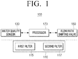
- FIG. 1 is a block diagram illustrating a simple configuration of a water purifier according to an embodiment.
- a water purifier 100 includes a filter 110 including a plurality of filters, a water quality sensor 130 for measuring the water quality of water provided to the water purifier 100 from a water supply source, a flow path shifting valve 150 for selectively providing water provided from the water supply source to a first filter 115 or a second filter 117, and a processor 170 for controlling the flow path shifting valve 150.
- the filter 110 includes a plurality of filters.
- the filter 110 includes the first filter 115 for filtering using a first method and the second filter 117 for filtering using a second method.
- the first filter 115 is composed of a direct-type membrane filter 115 for filtering water using a direct-type water purifying method.
- the filtered water in the filter 110 can be directly supplied to the user by the direct-type water purification, thereby improving the sanitation.
- the first filter 115 functions as a main filter for removing fine contaminants, and may be a filter having a high filtering force such as a hollow fiber membrane filter and a nano trap filter.
- the hollow fiber membrane filter (ultrafiltration filter, UF filter) is a porous filter having pores of a size of tens of nanometers to hundreds of nanometers (nm), and remove contaminants in the water through a large number of micropores distributed on the surface of the membrane.
- the nanotrap filter is a filter for adsorbing and removing bacteria, micro-viruses, and harmful substances by electrostatic force.
- the filter used in the first filter 115 is not limited to the hollow fiber membrane filter and the nano trap filter described above, but various filters having a direct-type water purification system which remove fine contaminants can be used.
- the second filter 117 is composed of a reverse osmosis filter for filtering water using reverse osmosis water purification method.
- the second filter 117 may include a reverse osmosis membrane and may purify water supplied through reverse osmosis, and may filter not only heavy metals such as lead and arsenic but also sodium, various pathogens, or the like.
- the second filter 117 functions as a main filter to remove fine contaminants, and typically a reverse osmosis membrane filter can be used.
- the reverse osmosis membrane filter is composed of a reverse osmosis membrane having fine pores, and can filter heavy metals such as lead and arsenic as well as sodium, various pathogens, or the like.
- the water quality sensor 130 measures water quality of water that is provided from the water supply source and flown into the water purifier 100.
- the water quality sensor 130 may be composed of a total dissolved solids (TDS) sensor for measuring the electrical conductivity of water provided from the water supply source.
- the water quality sensor 130 may further include a turbidity sensor for measuring the turbidity of water provided from the water supply source as the auxiliary sensor of the TDS sensor.
- the water quality sensor 130 may increase the accuracy of the measured water quality by adding a turbidity sensor to the TDS sensor.
- the water quality sensor 130 is composed of the TDS sensor, but the embodiment is not limited thereto, and the water quality sensor 130 can be configured to measure at least one of turbidity of water or the amount of ions contained in the water flown into the water purifier.
- the water quality sensor 130 may include at least one of a turbidity sensor, an ion sensor, and a TDS sensor.
- the flow path shifting valve 150 may provide the water provided from the water supply source selectively to the first filter 115 or the second filter 117.
- the water purifier 100 may include a water line through which water provided from a water supply source is discharged through a plurality of filters.
- the flow path shifting valve 150 may be provided on the water line.
- the water line may be branched from the flow path shifting valve 150 and may be formed to pass through the first filter 115 or the second filter 117.
- the flow path shifting valve 150 operates based on the water quality of the water sensed by the water quality sensor 130.
- the processor 170 may perform the control for each configuration in the water purifier 100. To be specific, the processor 170, upon receiving a water discharging command to provide drinking water from a user, may control a driver (not shown) to provide drinking water.
- the processor 170 controls the flow path shifting valve 150 based on the water quality of water sensed by the water quality sensor 130.
- the processor 170 controls the flow path shifting valve 150 to perform filtering according to the water quality of water measured by the water quality sensor 130.
- the processor 170 compares the water quality value measured by the water quality sensor 130 with a predetermined water quality value.
- the water quality value may be defined by a factor detected by the water quality sensor 130.
- the predetermined water quality value is the water quality value for the tap water supplied from the water source.
- the processor 170 controls the flow path shifting valve 150 so as to provide water to the direct-type first filter 115 when the measured water quality value is less than a predetermined water quality value, and provide water to the second filter 117 using reverse osmosis purification method when the measured water quality value is greater than a predetermined water quality value.
- the water quality value measured by the water quality sensor 130 is determined according to the amount of ions contained in the water or the turbidity of the water.
- the predetermined water quality value corresponds to the amount of ions contained in the tap water supplied from the water source and the turbidity of the water.
- the predetermined water quality value can be set to 50 ⁇ S or more and 250 ⁇ S or less, and the turbidity can be set to 0.5 NTU.
- the processor 170 may control the flow path shifting valve 150 to supply water to the first filter 115 using the direct-type water purification method.
- the water supplied from the water supply source to the water purifier 100 may contain more ions than the tap water, and can be turbid due to the abnormality in piping or introduction of the contaminant water.
- the water quality value of this water can be measured to be greater than or equal to about 500 ⁇ S of electrical conductivity or turbidity greater than or equal to 2.5 NTU, so that the water quality value is significantly greater than the predetermined water quality value.
- the processor 170 may control the flow path shifting valve 150 to supply water to the second filter 117, which is a reverse osmosis water purification method.
- the ionic material included in the water can be removed through the second filter 117.
- the water purifier 100 may perform filtering to be suitable to water quality of water measured by the water quality sensor 130. Accordingly, even when water of quality different from the water quality provided from the water source is provided, purified water that satisfies a predetermined criterion maybe provided. That is, regardless of flown water, a predetermined filtering level may be maintained.
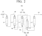
- FIG. 2 is an inside configuration map that briefly illustrates a water purification process of a water purifier according to an embodiment.
- the water purifier 100 includes the filter 110 including a plurality of filters, the water quality sensor 130 for measuring water quality of water supplied to the filter 110, and the flow path shifting valve 150 for shifting the flow path of the filter 110 for filtering water supplied to the filter 110 selectively using the direct-type water purification method or reverse osmosis water purification method.
- the filter 110 may include a pre-treatment filter 111, 113, the first filter 115, the second filter 117, and a post-treatment filter 119.
- the pre-treatment filters 111 and 113 may be composed of a sediment filter 111, which receives water from a water supply source and removes dust, debris, various floating materials through a fine filter in the size of about five micron and a pre-carbon filter 113 which removes chlorine components and chemicals harmful to the human body such as trihalomethanes (THM), a synthetic detergent, an insecticide, or the like, by using an adsorption method of activated carbon.
- THM trihalomethanes
- the first filter 115 may be composed of the hollow fiber membrane filter, nano trap filter, or the like, for removing fine contaminants.
- the second filter 117 may be composed of a reverse osmosis membrane filter 117 which is composed of a reverse osmosis membrane of 0.0001 micron for filtering not only heavy metals such as lead and arsenic but also sodium, various pathogens, or the like, and discharging the concentrated living water through a drain pipe 194.
- the post-treatment filter 119 may be composed of a post-carbon filter that is connected to the first filter 115 by a first water purifying line 195, and connected to the second filter 117 by a second water purifying line 193, for removing unpleasant taste, odor, coloring, or the like, included in water that passed through the first filter 115 and the second filter 117.
- the type or number of filters installed before or after the first and second filters 115 and 117 is not limited thereto.
- the pre-treatment filters 111 and 113 are respectively formed in the form of an independent cartridge, but the embodiment is not limited thereto, and the pre-treatment filters 111 and 113 may be formed of a composite filter having functions of two or more filters.
- the sediment filter 111 and the pre-carbon filter 113 may be configured as a single pre-treatment filter.
- the water quality sensor 130 may be installed in a water supply line 191 between the water supply source and the pre-treatment filters 111 and 113. To be specific, the water quality sensor 130 may be installed in the water supply line 191 between the water supply source and the sediment filter 111.
- the water quality sensor 130 measures the quality of water provided from the water supply source to the filter 110.
- the water purifier 100 may select a filter for supplying water according to the water quality value measured by the water quality sensor 130.
- the water supplied in accordance with the water quality value measured by the water quality sensor 130 may be selectively supplied to the first filter 115 or the second filter 117.
- the flow path shifting valve 150 may be installed at a point where a first water purifying line 195, between the pre-treatment filters 111 and 113 and the first filter 115, and a second water purifying line 193, between the pre-treatment filters 111 and 113 and the second filter 117, meet. Specifically, the flow path shifting valve 150 may be provided at a part at a lower end of the pre-carbon filter 113 where the second water purifying line 193 and the first water purifying line 195 are connected.
- the flow path shifting valve 150 may supply the water which passed the pre-treatment filters 111 and 113 to one side of the first filter 115 and the second filter 117 by the processor 170.
- the filter 110 may include a pre-treatment line 192 between the water supply line 191 and the first water purifying line 195 and the second water purifying line 193, through which water that passed at least one pre-treatment filter 111, 113 is discharged.
- the pre-treatment line 192 may filter the supplied water primarily.
- One side of the flow path shifting valve 150 may be connected to the pre-treatment line 192, and the other side thereof can be connected to the first water purifying line 195 and the second water purifying line 193, respectively.
- the flow path shifting valve 150 may switch the flow path to provide the water having passed through the pre-treatment filters 111 and 113 to the first filter 115 or the second filter 117 according to the measured water quality value.
- the flow path shifting valve 150 may shift the flow path so that the water that passed through the pre-treatment filters 111 and 113 flows to the first water purifying line 195 to be provided to the first filter 115.
- the flow path shifting valve 150 may shift the flow path so that the water that passed through the pre-treatment filters 111 and 113 flows to the second water purifying line 193 to be provided to the second filter 117.
- the first water purifying line 195 includes a first water purifying line front end 195a formed at the front end of the first filter 115 and a rear end 195b of the first water purifying line formed at the rear end of the first filter 115.
- the first water purifying line front end 195a is a flow path through which water passed through the pre-treatment filters 111 and 113 is supplied to the first filter 115
- the first water purifying line front end 195a is a flow path through which the water passing through the first filter 115 is provided to the post-treatment filter 119.
- the second water purifying line 193 includes a second water purifying line front end 193a formed at the front end of the second filter 117 and a second water purifying line rear end 193b formed at the rear end of the second filter 117.
- the second water purifying line front end 193a is a flow path through which water passed through the pre-treatment filters 111 and 113 is provided to the second filter 117
- the second water purifying line front end 193a is a flow path through which the water passing through the second filter 117 is provided to the post-treatment filter 119.
- the second filter 117 by the reverse osmosis water purification method has small flow rate and thus, by forming the second water purifying line rear end 193b in which the water which passed the second filter 117 flows to be long, flow rate of water collected in the second water purifying line 193 may be secured without including a separate water tank.
- the rear end 193b of the second water purifying line may be formed to be longer than a preset length in order to secure purified water that passed through the second filter 117, and the rear end 193b of the second water purifying line may be formed to be longer than the rear end 195b of the first water purifying line.
- the second water purifying line rear end 193b between the second filter 117 and the post-treatment filter 119 has been described as being long, it is not limited thereto, and the flow path through which the water having passed through the second filter 117 can be stored may be formed long.
- the water discharge line 197 formed at the rear end of the post-treatment filter 119 may be formed to be long, or the flow path connected to the cold/hot apparatus in the water discharge line 197 may be formed to be long.
- the filtered water from the second filter 117 is not drained from a water tank storing the separate purified water when the user presses the selection button to be drunken by the user, but the amount of water (about of 0.5 l) stored in the rear end 193b of the second water purifying line may be discharged through the water discharge line 197.
- the purified water can be directly supplied to the user even in the reverse osmosis water purification method passing through the second filter 117, thereby improving the hygiene. Since water can be stored in the second water purifying line 193 where water flows without using a separate water tank in which the purified water is stored, there is no concern for microbial contamination. In addition, unlike the water tank where a separate washing is required, the second water purifying line 193 can be cleaned by flowing the sterilized water therein, thereby facilitating washing and sterilization.
- Forming the flow path to be long may minimize the volume of the water purifier 100 rather than including a separate water tank and thus, the water purifier 100 of a compact structure may be provided.
- each of the first water purifying line 195 and the second water purifying line 193 may be connected to the flow path shifting valve 150, and the other end may be connected to the post-treatment filter 119.
- the rear end of post-treatment filter 119 may include the water discharge line 197 that supplies filtered water to the user.
- FIG. 3 is an inside configuration map that briefly illustrates a water purification process of a water purifier according to another embodiment.
- the water purifier 101 has mostly the same configuration as that of the water purifier 100 illustrated in FIG. 2 , except that the second water purifying line 193 of the filter 110 is arranged in a plurality of wound forms. Therefore, the water purifier 101 according to another embodiment will be described with reference to the different structure of the second water purifying line 193 and detailed description of the overlapped configuration that is the same as the water purifier 100 as illustrated in FIG. 2 will be omitted.
- the second water purifying line 193 includes the second water purifying line front end 193a formed at the front end of the second filter 117 and a second water purifying line rear end 193c formed at the rear end of the second filter 117.
- the second water purifying line front end 193a is a flow path through which water passed through the pre-treatment filters 111 and 113 is provided to the second filter 117
- the second water purifying line front end 193a is a flow path through which the water passing through the second filter 117 is provided to the post-treatment filter 119.
- the second water purifying line rear end 193c may be formed to be longer than a predetermined length in order to obtain the purified water passing through the second filter 117, and the second water purifying line rear end 193c may be formed to be longer than the first water purifying line rear end 195b.
- the second water purifying line rear end 193c may be arranged such that a part of an area of the second water purifying line rear end 193c for storing water that passed through the second filter 117 is in a plurality of wound forms.
- the water that passed through the second filter 117 may be stored in the second water purifying line rear end 193c that is wound in a plurality of times and thus, a separate water tank is not necessary and flow rate of water that is discharged in the second water purifying line 193 may be secured.
- the second water purifying line rear end 193c between the second filter 117 and the post-treatment filter 119 has been described as being arranged in a plurality of wound forms, but the embodiment is not limited thereto, and a plurality of wound areas may be formed in a flow path in which water than passed through the second filter 117 may be stored.
- FIG. 4 is an inside configuration map that briefly illustrates a water purification process of a water purifier according to still another embodiment.
- the water purifier 102 has mostly the same structure as the water purifier 100 illustrated in FIG. 2 , except that the flow sensors 141 and 142 are disposed in the first and second water purifying lines 195 and 193 of the filter 110, respectively. Accordingly, the water purifier 102 according to another embodiment will be described with respect to the structure in which the flow sensors 141 and 142 are disposed in the first and second water purifying lines 195 and 193, respectively, which is the different configuration, and overlapping configuration as the water purifier 100 as described in FIG. 2 will be omitted.
- the water purifier 102 may include the first flow sensor 141 for measuring an amount of water supplied to the first filter 115 and the second flow sensor 142 for measuring an amount of water supplied to the second filter 117.
- the first flow sensor 141 may be disposed in the first water purifying line 195, and specifically, may be disposed at the first water purifying line front end 195a. Since the first filter 115 is a direct-type water purification filter, the difference between the amount of water provided to the first filter 115 and the amount of water passing through the first filter 115 is small, so that the first flow sensor 141 can also be disposed at the rear end 195b of the first water purifying line.
- the second flow sensor 142 may be disposed in the second water purifying line 193, and may be specifically disposed at the second water purifying front end 193a. Since the second filter 117 is a reverse osmosis water purifying filter, a portion of the water passing through the second filter 117 is discharged through the drain pipe 194. Accordingly, the second flow sensor 142 may be disposed at the front end of the second filter 117 because the amount of water provided to the second filter 117 should be measured in order to measure the amount of water passing through the second filter 117.
- the water purifier 102 may include a notification device (not shown) for notifying the user of whether to replace a filter in the filter 110.
- Whether to replace the first filter 115 may be determined by the processor 170 through the amount of water passing through the first filter 115 measured by the first flow sensor 141, and whether the second filter 117 is replaced can be determined by the processor 170 through the amount of water passing through the second filter 117 measured by the second flow sensor 142.
- the processor 170 may generate a filter replacement notification signal when replacement of the first filter 115 or the second filter 117 is necessary.
- the notification device may guide the filter replacement to a user by receiving the filter replacement notification signal.
- the notification device may be configured as a device, such as a lighting, speaker, display, or the like.
- the notification device may be configured with communication technology (for example, near-field communication (NFC), etc.) to guide the user to filter replacement and to guide the user's mobile phone or guide the user's mobile phone to a dedicated application of the smartphone to enable the user's filter replacement order. Accordingly, the user can quickly respond to the need for replacement of the filter.
- NFC near-field communication
- the replacement timing of the first filter 115 and the second filter 117 is different from each other.
- the replacement timing of the first filter 115 is about 12 months and the replacement timing of the second filter 117 is about 24 months.
- the replacement timing of the first filter 115 and the second filter 117 is different so that if a consumer does not replace the filter, the water that is not filtered adequately may be discharged.
- the processor 170 can control the flow path shifting valve 150 so that water provided from the water supply source is supplied to only the second filter 117 when replacement of the first filter 115 is necessary.
- the water provided from the water supply source may be provided to the second filter 117 regardless of the measured water quality value. Since the life of the first filter 115 has been exhausted, water of which measured water quality value is less than a predetermined water quality value can also be filtered through the second filter 117.
- the processor 170 may not perform a water discharge command to discharge the purified water if the measured water quality value of the water provided from the water supply source is greater than the predetermined water quality value.
- Water having a water quality value greater than the predetermined water quality value must pass through the second filter 117 of the reverse osmosis type to provide purified water that satisfies a predetermined criterion. Therefore, if life of the second filter 117 is exhausted and the second filter 117 needs to be replaced, when water having a water quality value greater than a predetermined water quality value is supplied to the water purifier 102, the water purifier 100 can stop the supply of purified water.
- FIG. 5 is a flowchart illustrating a method for water purifying of a water purifier according to an embodiment.
- the water quality of the water supplied from the water supply source is measured by the water quality sensor 130 provided at the inlet end of the filter 110 in operation S510.
- the water quality value measured by the water quality sensor 130 is determined by considering at least one of turbidity or total dissolved solids (TDS).
- the water quality sensor 130 may be composed of the TDS sensor for measuring the conductivity of water.
- the supplied water is selectively provided to the first filter 115 with the direct-type water purification method or to the second filter 117 with the reverse osmosis water purification method.
- the water pollution level of water can be determined by comparing the water quality value measured by the water quality sensor 130 at the inlet end of the filter 110 with a predetermined water quality value. The higher the level of contamination of the water supplied from the water source, the higher the filtration performance of the filter is required.
- the preset water quality value can be set to the water quality value of the water quality of the tap water provided from the water supply source.
- the provided water is filtered by the first filter 115 in a direct-type water purification method. If the measured water quality value is greater than the predetermined water quality value, the provided water is filtered by the second filter 117 of the reverse osmosis water purification method.
- the water purifier 100 performs filtering by selecting a suitable filter according to the water quality of the water supplied to the filter 110. Accordingly, even when the groundwater containing the excess ions is introduced into the water purifier 100 or the harmful substance is introduced into the water purifier 100, such as when the water supply source is connected to an old pipe, the water purifier 100 may provide purified water that satisfies a predetermined criterion. That is, it is possible to maintain a predetermined filtering level regardless of the water being introduced.
- FIG. 6 is a flowchart illustrating a method for water purifying of a water purifier according to another embodiment.
- the amount of water supplied to the first filter 115 is measured by the first flow sensor 141 provided at the inlet end of the first filter 115, and the amount of water supplied to the second filter 117 from the second flow sensor 142 provided at the inlet end of the second filter 117 is measured in operation S610.
- the first filter 115 and the second filter 117 are different from each other in terms of the water purification method and thus, there may be a difference in the replacement timing. Accordingly, the amount of water introduced into each of the first filter 115 and the second filter 117 may be measured in order to determine the replacement timing of each of the first filter 115 and the second filter 117.
- Whether to replace the first filter 115 is determined based on the amount of water measured by the first flow sensor 141 at the inlet end of the first filter 115, and whether to replace the second filter 117 is determined based on the amount of water measured by the second flow sensor 142 at the inlet end of the second filter 117 in operation S620.
- the first reference value may be set to the allowable flow rate of the first filter 115.
- the second reference value may be set to the allowable flow rate of the second filter 117.
- the user can inform the user of the replacement of the first filter 115, and the water provided from the water supply source is provided only to the second filter 117 in operation S630.
- the output method of the filter replacement notification signal can output a message through a display, output an alarm sound through a speaker, or output both.
- the first filter 115 with the direct-type water purification method may be formed to have a shorter replacement timing than the second filter 117.
- the water purifier 100 may provide drinking water using the second filter 117.
- the second filter 117 with the reverse osmosis water purification method may perform a higher level of filtering than the first filter 115 and thus, water having a water quality value less than the predetermined water quality value may provide purified water that satisfies a predetermined criterion, even if the water is filtered by the second filter 117.
- the output method of the filter replacement notification signal can output a message through a display, output an alarm through a speaker, or output both.
- Water quality of water provided from the water supply source is measured in operation S651.
- the measured water quality value and the predetermined water quality value are compared in operation S652.
- water is provided to the first filter 115 as the basic control method of a water purifier in operation S653.
- the water purifier 100 can immediately discharge drinking water as the user presses a selection button of purified water such as cold water and hot water.
- a selection button of purified water such as cold water and hot water.
- the water discharge command is input to the water purifier 100.
- the second filter 117 needs to be replaced and the measured water quality value is greater than the predetermined water quality value, the water purifier may not operate to perform the water discharge command.
Landscapes
- Chemical & Material Sciences (AREA)
- Engineering & Computer Science (AREA)
- Water Supply & Treatment (AREA)
- Chemical Kinetics & Catalysis (AREA)
- Life Sciences & Earth Sciences (AREA)
- Nanotechnology (AREA)
- Hydrology & Water Resources (AREA)
- Organic Chemistry (AREA)
- Environmental & Geological Engineering (AREA)
- Electrochemistry (AREA)
- Biochemistry (AREA)
- General Health & Medical Sciences (AREA)
- General Physics & Mathematics (AREA)
- Immunology (AREA)
- Pathology (AREA)
- Analytical Chemistry (AREA)
- Health & Medical Sciences (AREA)
- Physics & Mathematics (AREA)
- Separation Using Semi-Permeable Membranes (AREA)
- Water Treatment By Sorption (AREA)
Description
- The invention relates to a water purifier and a control method thereof.
- Generally, a water purifier is a device for filtering water supplied from a water supply source to provide drinking water, and is widely used for a home use. Specifically, a water purifier may be connected to a water supply source, remove suspended or harmful components contained in water by using a filter, and purify water as much as desired according to a manipulation of a user to discharge purified water.
- As such, a water purifier that supplies drinkable water to a user should be provided to a user in a manner that purified water satisfies a predetermined criterion.
- In general, since a filter provided in a water purifier is configured in accordance with the water quality of tap water provided from a water source, it is not filtered according to impurities dissolved in water depending on the water quality of water provided to the water purifier.
- The related-art water purifier has problems in that there would be no filtering effect, if water such as groundwater that is different from waterworks is filtered, or the waterworks piping is aged, and the tap water supplied from the waterworks is filtered, and that an optimal action cannot be taken according to the water quality of the water provided to the water purifier.
-
- According to an aspect of the invention, there is provided a water purifier as set out in claim 1. According to another aspect of the invention, there is provided a method for controlling a water purifier as set out in claim 12. The invention relates to a water purifier that may select a filter according to water quality of water supplied from a water supply source and filter the water.
- The water purifier includes a water quality sensor configured to measure quality of water that is supplied from a water supply source, a first filter configured to filter by a first method, a second filter configured to filter by a second method, a flow path shifting valve configured to selectively supply water that is supplied from the water supply source to the first filter or the second filter, and a processor configured to control the flow path shifting valve based on a water quality value that is measured by the sensor.
- The first method is a direct-type water purification method, and the second method is a reverse osmosis water purification method.
- The processor is configured to control the flow path shifting valve to, based on the measured water quality value being less than a predetermined water quality value supply the water supplied from the water supply source to the first filter, and based on the measured water quality value being greater than a predetermined water quality value, supply the water supplied from the water supply source to the second filter.
- The water purifier further comprises a first water purifying line, which includes a first water purifying line front end formed at the front end of the first filter, and a first water purifying line rear end formed at the rear end of the first filter between the first filter and a water discharge line to discharge purified water, and a second water purifying line which includes a second water purifying line front end formed at the front end of the second filter, and a second water purifying line rear end formed at the rear end of the second filter between the second filter and the water discharge line, and the second water purifying line rear end may be formed to be longer than the first water purifying line rear end.
- The second water purifying line rear end may be disposed in a form to be wound by a plurality of times.
- The water quality sensor may measure electrical conductivity of the water supplied from the water supply source.
- The water purifier may further include a pre-treatment filter receiving the water supplied from the water supply source before the first filter and the second filter, and a post-treatment filter receiving water from the first filter and the second filter.
- The flow path shifting valve may selectively supply the water that is discharged from the pre-treatment filter to the first filter or the second filter.
- The water quality sensor may detect quality of water that is supplied to the pre-treatment filter.
- The water purifier may include a first flow sensor configured to detect an amount of the water that is supplied to the first filter and a second flow sensor configured to detect an amount of the water that is supplied to the second filter.
- The processor may determine whether to replace the first filter based on the amount of water that is measured by the first flow sensor, and determine whether to replace the second filter based on the amount of water that is measured by the second flow sensor.
- The processor may, in response to determination that the first filter needs to be replaced, generate a filter replacement notification signal, and control the flow path shifting valve to supply the water supplied from the water supply source only to the first filter.
- The processor may, based on determination that the second filter needs to be replaced, generate a filter replacement notification signal, and based on the measured water quality value being greater than a predetermined water quality value, not to perform a water discharge command to discharge purified water.
- According to the invention, a method for controlling a water purifier is also provided. The method includes measuring quality of water that is suppled from a water supply source; and selectively supplying water that is supplied from the water supply source to the first filter or the second filter based on a measured water quality value.
- The first method is a direct-type water purification method, and the second method is a reverse osmosis water purification method.
- The supplying to the first filter or the second filter includes, based on the measured water quality value being less than a predetermined water quality value, supplying the water supplied from the water supply source to the first filter, and based on the measured water quality value being greater than a predetermined water quality value, supplying the water supplied from the water supply source to the second filter.
- The method may further include detecting an amount of the water that is supplied to the first filter and the second filter, respectively.
- Whether to replace the first filter or the second filter may be determined based on the detected amount of water that is supplied to the first filter and the second filter.
- In response to determination that the first filter needs to be replaced, a filter replacement notification signal may be generated, and the water supplied from the water supply source may be supplied only to the second filter.
- Based on determination that the second filter needs to be replaced, a filter replacement notification signal may be generated, and based on the measured water quality value being greater than a predetermined water quality value, a water discharge command to discharge purified water may not be performed.
- The above and other aspects, features, and advantages of certain embodiments of the invention will be more apparent from the following description taken in conjunction with the accompanying drawings, in which:
-
FIG. 1 is a block diagram illustrating a simple configuration of a water purifier according to an embodiment; -
FIG. 2 is an inside configuration map that briefly illustrates a water purification process of a water purifier according to an embodiment; -
FIG. 3 is an inside configuration map that briefly illustrates a water purification process of a water purifier according to another embodiment; -
FIG. 4 is an inside configuration map that briefly illustrates a water purification process of a water purifier according to still another embodiment; -
FIG. 5 is a flowchart illustrating a method for water purifying of a water purifier according to an embodiment; and -
FIG. 6 is a flowchart illustrating a method for water purifying of a water purifier according to another embodiment. - Throughout the drawings, like reference numerals will be understood to refer to like parts, components, and structures.
- Hereinafter, embodiments of the water purifier and a control method thereof will be further described.
- Examples described hereinafter are for easy understanding of the invention, which is defined by the claims.
- In addition, in the following description, detailed descriptions of well-known functions or configurations will be omitted since they would unnecessarily obscure the subject matters of the invention.
- In addition, it should be noted that the drawings as attached are just for easy understanding of the invention, and are not illustrated as really scaled, and dimensions of some elements may be exaggerated.
- Hereinafter, with reference to the accompanying drawings, embodiments will be described in detail.
-
FIG. 1 is a block diagram illustrating a simple configuration of a water purifier according to an embodiment. - Referring to
FIG. 1 , awater purifier 100 according to an embodiment includes afilter 110 including a plurality of filters, awater quality sensor 130 for measuring the water quality of water provided to thewater purifier 100 from a water supply source, a flowpath shifting valve 150 for selectively providing water provided from the water supply source to afirst filter 115 or asecond filter 117, and aprocessor 170 for controlling the flowpath shifting valve 150. - The
filter 110 includes a plurality of filters. To be specific, thefilter 110 includes thefirst filter 115 for filtering using a first method and thesecond filter 117 for filtering using a second method. - The
first filter 115 is composed of a direct-type membrane filter 115 for filtering water using a direct-type water purifying method. - By not using the water storage tank provided inside the water treatment device for water filtered by the
filter 110, the filtered water in thefilter 110 can be directly supplied to the user by the direct-type water purification, thereby improving the sanitation. - The
first filter 115 functions as a main filter for removing fine contaminants, and may be a filter having a high filtering force such as a hollow fiber membrane filter and a nano trap filter. At this time, the hollow fiber membrane filter (ultrafiltration filter, UF filter) is a porous filter having pores of a size of tens of nanometers to hundreds of nanometers (nm), and remove contaminants in the water through a large number of micropores distributed on the surface of the membrane. In addition, the nanotrap filter is a filter for adsorbing and removing bacteria, micro-viruses, and harmful substances by electrostatic force. However, the filter used in thefirst filter 115 is not limited to the hollow fiber membrane filter and the nano trap filter described above, but various filters having a direct-type water purification system which remove fine contaminants can be used. - The
second filter 117 is composed of a reverse osmosis filter for filtering water using reverse osmosis water purification method. - The
second filter 117 may include a reverse osmosis membrane and may purify water supplied through reverse osmosis, and may filter not only heavy metals such as lead and arsenic but also sodium, various pathogens, or the like. - The
second filter 117 functions as a main filter to remove fine contaminants, and typically a reverse osmosis membrane filter can be used. At this time, the reverse osmosis membrane filter (RO filter) is composed of a reverse osmosis membrane having fine pores, and can filter heavy metals such as lead and arsenic as well as sodium, various pathogens, or the like. - The
water quality sensor 130 measures water quality of water that is provided from the water supply source and flown into thewater purifier 100. - The
water quality sensor 130 may be composed of a total dissolved solids (TDS) sensor for measuring the electrical conductivity of water provided from the water supply source. In addition, thewater quality sensor 130 may further include a turbidity sensor for measuring the turbidity of water provided from the water supply source as the auxiliary sensor of the TDS sensor. Thewater quality sensor 130 may increase the accuracy of the measured water quality by adding a turbidity sensor to the TDS sensor. - It has been described that the
water quality sensor 130 is composed of the TDS sensor, but the embodiment is not limited thereto, and thewater quality sensor 130 can be configured to measure at least one of turbidity of water or the amount of ions contained in the water flown into the water purifier. In other words, thewater quality sensor 130 may include at least one of a turbidity sensor, an ion sensor, and a TDS sensor. - The flow
path shifting valve 150 may provide the water provided from the water supply source selectively to thefirst filter 115 or thesecond filter 117. Thewater purifier 100 may include a water line through which water provided from a water supply source is discharged through a plurality of filters. The flowpath shifting valve 150 may be provided on the water line. The water line may be branched from the flowpath shifting valve 150 and may be formed to pass through thefirst filter 115 or thesecond filter 117. The flowpath shifting valve 150 operates based on the water quality of the water sensed by thewater quality sensor 130. - The
processor 170 may perform the control for each configuration in thewater purifier 100. To be specific, theprocessor 170, upon receiving a water discharging command to provide drinking water from a user, may control a driver (not shown) to provide drinking water. - The
processor 170 controls the flowpath shifting valve 150 based on the water quality of water sensed by thewater quality sensor 130. Theprocessor 170 controls the flowpath shifting valve 150 to perform filtering according to the water quality of water measured by thewater quality sensor 130. - The
processor 170 compares the water quality value measured by thewater quality sensor 130 with a predetermined water quality value. Here, the water quality value may be defined by a factor detected by thewater quality sensor 130. The predetermined water quality value is the water quality value for the tap water supplied from the water source. - To be specific, the
processor 170 controls the flowpath shifting valve 150 so as to provide water to the direct-typefirst filter 115 when the measured water quality value is less than a predetermined water quality value, and provide water to thesecond filter 117 using reverse osmosis purification method when the measured water quality value is greater than a predetermined water quality value. - The water quality value measured by the
water quality sensor 130 is determined according to the amount of ions contained in the water or the turbidity of the water. In this case, the predetermined water quality value corresponds to the amount of ions contained in the tap water supplied from the water source and the turbidity of the water. The predetermined water quality value can be set to 50 µS or more and 250 µS or less, and the turbidity can be set to 0.5 NTU. - Accordingly, when the measured water contains ions in the similar level of tap water, the
processor 170 may control the flowpath shifting valve 150 to supply water to thefirst filter 115 using the direct-type water purification method. - The water supplied from the water supply source to the
water purifier 100 may contain more ions than the tap water, and can be turbid due to the abnormality in piping or introduction of the contaminant water. The water quality value of this water can be measured to be greater than or equal to about 500 µS of electrical conductivity or turbidity greater than or equal to 2.5 NTU, so that the water quality value is significantly greater than the predetermined water quality value. In this case, theprocessor 170 may control the flowpath shifting valve 150 to supply water to thesecond filter 117, which is a reverse osmosis water purification method. The ionic material included in the water can be removed through thesecond filter 117. - The
water purifier 100 according to an embodiment may perform filtering to be suitable to water quality of water measured by thewater quality sensor 130. Accordingly, even when water of quality different from the water quality provided from the water source is provided, purified water that satisfies a predetermined criterion maybe provided. That is, regardless of flown water, a predetermined filtering level may be maintained. -
FIG. 2 is an inside configuration map that briefly illustrates a water purification process of a water purifier according to an embodiment. - Referring to
FIG. 2 , thewater purifier 100 includes thefilter 110 including a plurality of filters, thewater quality sensor 130 for measuring water quality of water supplied to thefilter 110, and the flowpath shifting valve 150 for shifting the flow path of thefilter 110 for filtering water supplied to thefilter 110 selectively using the direct-type water purification method or reverse osmosis water purification method. - The
filter 110 may include apre-treatment filter first filter 115, thesecond filter 117, and apost-treatment filter 119. - The pre-treatment filters 111 and 113 may be composed of a
sediment filter 111, which receives water from a water supply source and removes dust, debris, various floating materials through a fine filter in the size of about five micron and apre-carbon filter 113 which removes chlorine components and chemicals harmful to the human body such as trihalomethanes (THM), a synthetic detergent, an insecticide, or the like, by using an adsorption method of activated carbon. - The
first filter 115 may be composed of the hollow fiber membrane filter, nano trap filter, or the like, for removing fine contaminants. - The
second filter 117 may be composed of a reverseosmosis membrane filter 117 which is composed of a reverse osmosis membrane of 0.0001 micron for filtering not only heavy metals such as lead and arsenic but also sodium, various pathogens, or the like, and discharging the concentrated living water through adrain pipe 194. - The
post-treatment filter 119 may be composed of a post-carbon filter that is connected to thefirst filter 115 by a firstwater purifying line 195, and connected to thesecond filter 117 by a secondwater purifying line 193, for removing unpleasant taste, odor, coloring, or the like, included in water that passed through thefirst filter 115 and thesecond filter 117. - However, the type or number of filters installed before or after the first and
second filters FIG. 2 , it has been illustrated that thepre-treatment filters pre-treatment filters sediment filter 111 and thepre-carbon filter 113 may be configured as a single pre-treatment filter. - The
water quality sensor 130 may be installed in awater supply line 191 between the water supply source and thepre-treatment filters water quality sensor 130 may be installed in thewater supply line 191 between the water supply source and thesediment filter 111. - The
water quality sensor 130 measures the quality of water provided from the water supply source to thefilter 110. Thewater purifier 100 may select a filter for supplying water according to the water quality value measured by thewater quality sensor 130. - The water supplied in accordance with the water quality value measured by the
water quality sensor 130 may be selectively supplied to thefirst filter 115 or thesecond filter 117. - The flow
path shifting valve 150 may be installed at a point where a firstwater purifying line 195, between thepre-treatment filters first filter 115, and a secondwater purifying line 193, between thepre-treatment filters second filter 117, meet. Specifically, the flowpath shifting valve 150 may be provided at a part at a lower end of thepre-carbon filter 113 where the secondwater purifying line 193 and the firstwater purifying line 195 are connected. - The flow
path shifting valve 150 may supply the water which passed thepre-treatment filters first filter 115 and thesecond filter 117 by theprocessor 170. - The
filter 110 may include apre-treatment line 192 between thewater supply line 191 and the firstwater purifying line 195 and the secondwater purifying line 193, through which water that passed at least onepre-treatment filter pre-treatment line 192 may filter the supplied water primarily. - One side of the flow
path shifting valve 150 may be connected to thepre-treatment line 192, and the other side thereof can be connected to the firstwater purifying line 195 and the secondwater purifying line 193, respectively. The flowpath shifting valve 150 may switch the flow path to provide the water having passed through thepre-treatment filters first filter 115 or thesecond filter 117 according to the measured water quality value. - For example, when the measured water quality value is equal to or less than the preset water quality value, the flow
path shifting valve 150 may shift the flow path so that the water that passed through thepre-treatment filters water purifying line 195 to be provided to thefirst filter 115. For example, when the measured water quality value exceeds the preset water quality value, the flowpath shifting valve 150 may shift the flow path so that the water that passed through thepre-treatment filters water purifying line 193 to be provided to thesecond filter 117. - The first
water purifying line 195 includes a first water purifying linefront end 195a formed at the front end of thefirst filter 115 and arear end 195b of the first water purifying line formed at the rear end of thefirst filter 115. The first water purifying linefront end 195a is a flow path through which water passed through thepre-treatment filters first filter 115, and the first water purifying linefront end 195a is a flow path through which the water passing through thefirst filter 115 is provided to thepost-treatment filter 119. - The second
water purifying line 193 includes a second water purifying linefront end 193a formed at the front end of thesecond filter 117 and a second water purifying linerear end 193b formed at the rear end of thesecond filter 117. The second water purifying linefront end 193a is a flow path through which water passed through thepre-treatment filters second filter 117, and the second water purifying linefront end 193a is a flow path through which the water passing through thesecond filter 117 is provided to thepost-treatment filter 119. - The
second filter 117 by the reverse osmosis water purification method has small flow rate and thus, by forming the second water purifying linerear end 193b in which the water which passed thesecond filter 117 flows to be long, flow rate of water collected in the secondwater purifying line 193 may be secured without including a separate water tank. - The
rear end 193b of the second water purifying line may be formed to be longer than a preset length in order to secure purified water that passed through thesecond filter 117, and therear end 193b of the second water purifying line may be formed to be longer than therear end 195b of the first water purifying line. - Although the second water purifying line
rear end 193b between thesecond filter 117 and thepost-treatment filter 119 has been described as being long, it is not limited thereto, and the flow path through which the water having passed through thesecond filter 117 can be stored may be formed long. For example, thewater discharge line 197 formed at the rear end of thepost-treatment filter 119 may be formed to be long, or the flow path connected to the cold/hot apparatus in thewater discharge line 197 may be formed to be long. - The filtered water from the
second filter 117 is not drained from a water tank storing the separate purified water when the user presses the selection button to be drunken by the user, but the amount of water (about of 0.5 ℓ) stored in therear end 193b of the second water purifying line may be discharged through thewater discharge line 197. - By forming the flow path that has passed through the
second filter 117 to be long, the purified water can be directly supplied to the user even in the reverse osmosis water purification method passing through thesecond filter 117, thereby improving the hygiene. Since water can be stored in the secondwater purifying line 193 where water flows without using a separate water tank in which the purified water is stored, there is no concern for microbial contamination. In addition, unlike the water tank where a separate washing is required, the secondwater purifying line 193 can be cleaned by flowing the sterilized water therein, thereby facilitating washing and sterilization. - Forming the flow path to be long may minimize the volume of the
water purifier 100 rather than including a separate water tank and thus, thewater purifier 100 of a compact structure may be provided. - One end of each of the first
water purifying line 195 and the secondwater purifying line 193 may be connected to the flowpath shifting valve 150, and the other end may be connected to thepost-treatment filter 119. The rear end ofpost-treatment filter 119 may include thewater discharge line 197 that supplies filtered water to the user. -
FIG. 3 is an inside configuration map that briefly illustrates a water purification process of a water purifier according to another embodiment. - Referring to
FIG. 3 , thewater purifier 101 according to another embodiment has mostly the same configuration as that of thewater purifier 100 illustrated inFIG. 2 , except that the secondwater purifying line 193 of thefilter 110 is arranged in a plurality of wound forms. Therefore, thewater purifier 101 according to another embodiment will be described with reference to the different structure of the secondwater purifying line 193 and detailed description of the overlapped configuration that is the same as thewater purifier 100 as illustrated inFIG. 2 will be omitted. - The second
water purifying line 193 includes the second water purifying linefront end 193a formed at the front end of thesecond filter 117 and a second water purifying linerear end 193c formed at the rear end of thesecond filter 117. The second water purifying linefront end 193a is a flow path through which water passed through thepre-treatment filters second filter 117, and the second water purifying linefront end 193a is a flow path through which the water passing through thesecond filter 117 is provided to thepost-treatment filter 119. - The second water purifying line
rear end 193c may be formed to be longer than a predetermined length in order to obtain the purified water passing through thesecond filter 117, and the second water purifying linerear end 193c may be formed to be longer than the first water purifying linerear end 195b. The second water purifying linerear end 193c may be arranged such that a part of an area of the second water purifying linerear end 193c for storing water that passed through thesecond filter 117 is in a plurality of wound forms. - Accordingly, the water that passed through the
second filter 117 may be stored in the second water purifying linerear end 193c that is wound in a plurality of times and thus, a separate water tank is not necessary and flow rate of water that is discharged in the secondwater purifying line 193 may be secured. - It has been described that the second water purifying line
rear end 193c between thesecond filter 117 and thepost-treatment filter 119 has been described as being arranged in a plurality of wound forms, but the embodiment is not limited thereto, and a plurality of wound areas may be formed in a flow path in which water than passed through thesecond filter 117 may be stored. By winding the flow path which passed through thesecond filter 117 for several times to be long, the volume of thewater purifier 101 can be minimized, and thewater purifier 101 having a compact structure may be provided. -
FIG. 4 is an inside configuration map that briefly illustrates a water purification process of a water purifier according to still another embodiment. - Referring to
FIG. 4 , thewater purifier 102 according to another embodiment has mostly the same structure as thewater purifier 100 illustrated inFIG. 2 , except that theflow sensors water purifying lines filter 110, respectively. Accordingly, thewater purifier 102 according to another embodiment will be described with respect to the structure in which theflow sensors water purifying lines water purifier 100 as described inFIG. 2 will be omitted. - The
water purifier 102 may include thefirst flow sensor 141 for measuring an amount of water supplied to thefirst filter 115 and thesecond flow sensor 142 for measuring an amount of water supplied to thesecond filter 117. - The
first flow sensor 141 may be disposed in the firstwater purifying line 195, and specifically, may be disposed at the first water purifying linefront end 195a. Since thefirst filter 115 is a direct-type water purification filter, the difference between the amount of water provided to thefirst filter 115 and the amount of water passing through thefirst filter 115 is small, so that thefirst flow sensor 141 can also be disposed at therear end 195b of the first water purifying line. - The
second flow sensor 142 may be disposed in the secondwater purifying line 193, and may be specifically disposed at the second water purifyingfront end 193a. Since thesecond filter 117 is a reverse osmosis water purifying filter, a portion of the water passing through thesecond filter 117 is discharged through thedrain pipe 194. Accordingly, thesecond flow sensor 142 may be disposed at the front end of thesecond filter 117 because the amount of water provided to thesecond filter 117 should be measured in order to measure the amount of water passing through thesecond filter 117. - The
water purifier 102 according to an embodiment may include a notification device (not shown) for notifying the user of whether to replace a filter in thefilter 110. - Whether to replace the
first filter 115 may be determined by theprocessor 170 through the amount of water passing through thefirst filter 115 measured by thefirst flow sensor 141, and whether thesecond filter 117 is replaced can be determined by theprocessor 170 through the amount of water passing through thesecond filter 117 measured by thesecond flow sensor 142. - The
processor 170 may generate a filter replacement notification signal when replacement of thefirst filter 115 or thesecond filter 117 is necessary. The notification device may guide the filter replacement to a user by receiving the filter replacement notification signal. - The notification device may be configured as a device, such as a lighting, speaker, display, or the like. In addition, the notification device may be configured with communication technology (for example, near-field communication (NFC), etc.) to guide the user to filter replacement and to guide the user's mobile phone or guide the user's mobile phone to a dedicated application of the smartphone to enable the user's filter replacement order. Accordingly, the user can quickly respond to the need for replacement of the filter.
- The replacement timing of the
first filter 115 and thesecond filter 117 is different from each other. The replacement timing of thefirst filter 115 is about 12 months and the replacement timing of thesecond filter 117 is about 24 months. The replacement timing of thefirst filter 115 and thesecond filter 117 is different so that if a consumer does not replace the filter, the water that is not filtered adequately may be discharged. - In order to prevent this problem, the
processor 170 can control the flowpath shifting valve 150 so that water provided from the water supply source is supplied to only thesecond filter 117 when replacement of thefirst filter 115 is necessary. In this case, the water provided from the water supply source may be provided to thesecond filter 117 regardless of the measured water quality value. Since the life of thefirst filter 115 has been exhausted, water of which measured water quality value is less than a predetermined water quality value can also be filtered through thesecond filter 117. - If the
second filter 117 needs to be replaced, theprocessor 170 may not perform a water discharge command to discharge the purified water if the measured water quality value of the water provided from the water supply source is greater than the predetermined water quality value. Water having a water quality value greater than the predetermined water quality value must pass through thesecond filter 117 of the reverse osmosis type to provide purified water that satisfies a predetermined criterion. Therefore, if life of thesecond filter 117 is exhausted and thesecond filter 117 needs to be replaced, when water having a water quality value greater than a predetermined water quality value is supplied to thewater purifier 102, thewater purifier 100 can stop the supply of purified water. -
FIG. 5 is a flowchart illustrating a method for water purifying of a water purifier according to an embodiment. - Referring to
FIG. 5 , the water quality of the water supplied from the water supply source is measured by thewater quality sensor 130 provided at the inlet end of thefilter 110 in operation S510. The water quality value measured by thewater quality sensor 130 is determined by considering at least one of turbidity or total dissolved solids (TDS). Preferably, thewater quality sensor 130 may be composed of the TDS sensor for measuring the conductivity of water. - Based on the water quality value measured by the
water quality sensor 130 at the inlet end of thefilter 110, the supplied water is selectively provided to thefirst filter 115 with the direct-type water purification method or to thesecond filter 117 with the reverse osmosis water purification method. - Specifically, the water pollution level of water can be determined by comparing the water quality value measured by the
water quality sensor 130 at the inlet end of thefilter 110 with a predetermined water quality value. The higher the level of contamination of the water supplied from the water source, the higher the filtration performance of the filter is required. The preset water quality value can be set to the water quality value of the water quality of the tap water provided from the water supply source. - If the measured water quality value is less than or equal to the predetermined water quality value, the provided water is filtered by the
first filter 115 in a direct-type water purification method. If the measured water quality value is greater than the predetermined water quality value, the provided water is filtered by thesecond filter 117 of the reverse osmosis water purification method. - The
water purifier 100 according to an embodiment performs filtering by selecting a suitable filter according to the water quality of the water supplied to thefilter 110. Accordingly, even when the groundwater containing the excess ions is introduced into thewater purifier 100 or the harmful substance is introduced into thewater purifier 100, such as when the water supply source is connected to an old pipe, thewater purifier 100 may provide purified water that satisfies a predetermined criterion. That is, it is possible to maintain a predetermined filtering level regardless of the water being introduced. -
FIG. 6 is a flowchart illustrating a method for water purifying of a water purifier according to another embodiment. - Referring to
FIG. 6 , first, the amount of water supplied to thefirst filter 115 is measured by thefirst flow sensor 141 provided at the inlet end of thefirst filter 115, and the amount of water supplied to thesecond filter 117 from thesecond flow sensor 142 provided at the inlet end of thesecond filter 117 is measured in operation S610. - The
first filter 115 and thesecond filter 117 are different from each other in terms of the water purification method and thus, there may be a difference in the replacement timing. Accordingly, the amount of water introduced into each of thefirst filter 115 and thesecond filter 117 may be measured in order to determine the replacement timing of each of thefirst filter 115 and thesecond filter 117. - Whether to replace the
first filter 115 is determined based on the amount of water measured by thefirst flow sensor 141 at the inlet end of thefirst filter 115, and whether to replace thesecond filter 117 is determined based on the amount of water measured by thesecond flow sensor 142 at the inlet end of thesecond filter 117 in operation S620. - If the amount of water measured by the
first flow sensor 141 is greater than the first reference value, it is determined that the replacement timing of thefirst filter 115 has been reached. Here, the first reference value may be set to the allowable flow rate of thefirst filter 115. - If the amount of water measured by the
second flow sensor 142 is greater than the second reference value, it is determined that the replacement timing of thesecond filter 117 is reached. Here, the second reference value may be set to the allowable flow rate of thesecond filter 117. - If it is determined that replacement of the
first filter 115 is necessary, the user can inform the user of the replacement of thefirst filter 115, and the water provided from the water supply source is provided only to thesecond filter 117 in operation S630. The output method of the filter replacement notification signal can output a message through a display, output an alarm sound through a speaker, or output both. - In general, the
first filter 115 with the direct-type water purification method may be formed to have a shorter replacement timing than thesecond filter 117. In order to improve user's filter replacement convenience, if the life of thefirst filter 115 is exhausted, even if thefirst filter 115 is not replaced, thewater purifier 100 may provide drinking water using thesecond filter 117. - Since the
second filter 117 with the reverse osmosis water purification method may perform a higher level of filtering than thefirst filter 115 and thus, water having a water quality value less than the predetermined water quality value may provide purified water that satisfies a predetermined criterion, even if the water is filtered by thesecond filter 117. - In the meantime, if it is determined that the
second filter 117 needs to be replaced, the user informs the user of the replacement of thesecond filter 117 in operation S650. The output method of the filter replacement notification signal can output a message through a display, output an alarm through a speaker, or output both. - Water quality of water provided from the water supply source is measured in operation S651. The measured water quality value and the predetermined water quality value are compared in operation S652.
- When the measured water quality value is not greater than the predetermined water quality value, water is provided to the
first filter 115 as the basic control method of a water purifier in operation S653. - When the measured water quality value is greater than the predetermined water quality value, user's water discharge command will not be performed in operation S654.
- The
water purifier 100 can immediately discharge drinking water as the user presses a selection button of purified water such as cold water and hot water. When the selection button is pressed to supply the water inside thefilter 110, the water discharge command is input to thewater purifier 100. At this time, if thesecond filter 117 needs to be replaced and the measured water quality value is greater than the predetermined water quality value, the water purifier may not operate to perform the water discharge command. - These processes may be performed on a real-time basis.
- While various embodiments have been illustrated and described with reference to certain drawings, the invention is not limited to specific embodiments or the drawings, and it will be understood by those of ordinary skill in the art that various changes in form and details may be made therein as long as they fall within the scope as defined by the following claims.
Claims (12)
- A water purifier comprising:a water quality sensor (130) configured to measure a water quality value of water supplied from a water supply source, wherein the water quality sensor (130) includes at least one of a total dissolved solids (TDS) sensor, a turbidity sensor, and an ion sensor and the water quality value corresponds to the amount of ions contained in the water or the turbidity of the water;a first filter (115) configured to filter, by a first method, water supplied to the first filter (115) to remove fine contaminants;a second filter (117) configured to filter, by a second method different to the first method, water supplied to the second filter (117);a first water purifying line (195), which includes a first water purifying line front end (195a) formed at the front end of the first filter (115) and a first water purifying line rear end (195b) formed at the rear end of the first filter (115) between the first filter (115) and a water discharge line (197) to provide the water filtered by the first filter (115) to the water discharge line (197);a second water purifying line (193), which includes a second water purifying line front end (193a) formed at the front end of the second filter (117) and a second water purifying line rear end (193b) formed at the rear end of the second filter (117) between the second filter (117) and the water discharge line (197) to provide the water filtered by the second filter (117) to the water discharge line (197);a flow path shifting valve (150) configured to be controlled to selectively supply water that is supplied from the water supply source to only one of the first filter (115) via the first water purifying line front end (195a) and the second filter (117) via the second water purifying line front end (193a); anda processor (170) configured to control the flow path shifting valve (150) based on the water quality value measured by the sensor (130),wherein the first method is a direct-type water purification method according to which the first filter (115) is directly connected to the point of use, so that the water filtered by the first filter (115) can be supplied directly to a user, without having to be stored first in a water storage tank, and the second method is a reverse osmosis water purification method, andwherein the processor (170) is further configured to control the flow path shifting valve (150) to, based on the measured water quality value being less than a predetermined water quality value, supply the water supplied from the water supply source to the first water purifying line front end (195a), the first filter (115), the first water purifying line rear end (195b), and the water discharge line (197), and based on the water quality value being greater than the predetermined water quality value, supply the water supplied from the water supply source to the second water purifying line front end (193a), the second filter (117), the second water purifying line rear end (193b), and the water discharge line (197).
- The water purifier of claim 1,
wherein the second water purifying line rear end (193b) is longer than the first water purifying line rear end (195b). - The water purifier of claim 2, wherein the second water purifying line rear end (193b) is wound a plurality of times.
- The water purifier of claim 1, wherein the water quality sensor is configured to measure electrical conductivity of the water supplied from the water supply source, to thereby measure the water quality value of the water supplied from the water supply source.
- The water purifier of claim 1, further comprising:a pre-treatment filter (111, 113) configured to receive, and then filter, the water supplied from the water supply source before being selectively supplied by the flow path shifting valve to the first filter or the second filter; anda post-treatment filter (119) configured to receive, and then filter, the water filtered by the first filter and the water filtered by the second filter.
- The water purifier of claim 5, wherein the flow path shifting valve is configured to selectively supply the water filtered by the pre-treatment filter to only one of the first filter or the second filter.
- The water purifier of claim 5, wherein the water quality sensor is configured to measure the water quality value of water supplied from the water supply source before being received by the pre-treatment filter.
- The water purifier of claim 1, further comprising:a first flow sensor (141) configured to measure an amount of the water supplied to the first filter; anda second flow sensor (142) configured to measure an amount of the water supplied to the second filter.
- The water purifier of claim 8, wherein the processor is further configured to determine whether to replace the first filter based on the amount of water measured by the first flow sensor, and determine whether to replace the second filter based on the amount of water measured by the second flow sensor.
- The water purifier of claim 9, wherein the processor is further configured to, based on determining that the first filter is to be replaced, generate a filter replacement notification signal, and control the flow path shifting valve to supply the water supplied from the water supply source to the second filter and not the first filter.
- The water purifier of claim 9, wherein the processor is further configured to:based on determining that the second filter is to be replaced, generate a filter replacement notification signal, andbased on determining that the second filter is to be replaced and the measured water quality value being greater than a predetermined water quality value, controlling so as to not to perform a water discharge command to discharge purified water.
- A method for controlling the water purifier of anyone of claims 1 to 11, the method comprising:measuring a water quality value of water supplied to the water purifier from a water supply source, using the water quality sensor (130) of the water purifier, wherein the water quality value corresponds to the amount of ions contained in the water or the turbidity of the water; andselectively supplying the water supplied from the water supply source to only one of the first filter (115) to remove fine contaminants and the second filter (117) based on the measured water quality value,wherein the first method is a direct-type water purification method according to which the first filter (115) is directly connected to the point of use, so that the water filtered by the first filter (115) can be supplied directly to a user, without having to be stored first in a water storage tank, and the second method is different to the first method and is a reverse osmosis water purification method, andwherein the processor (170) controls the flow path shifting valve (150) based on the water quality value measured by the sensor (130), so that:
the water is supplied from the water supply source to the first water purifying line front end (195a), the first filter (115), the first water purifying line rear end (195b), and the water discharge line (197) when the measured water quality value is less than a predetermined water quality value, and the water is supplied from the water supply source to the second water purifying line front end (193a), the second filter (117), the second water purifying line rear end (193b), and the water discharge line (197) when the water quality value is greater than the predetermined water quality value.
Applications Claiming Priority (1)
| Application Number | Priority Date | Filing Date | Title |
|---|---|---|---|
| KR1020180156682A KR102934705B1 (en) | 2018-12-07 | 2018-12-07 | Water purifier and control method of the same |
Publications (2)
| Publication Number | Publication Date |
|---|---|
| EP3663266A1 EP3663266A1 (en) | 2020-06-10 |
| EP3663266B1 true EP3663266B1 (en) | 2022-08-03 |
Family
ID=68771558
Family Applications (1)
| Application Number | Title | Priority Date | Filing Date |
|---|---|---|---|
| EP19213617.4A Active EP3663266B1 (en) | 2018-12-07 | 2019-12-04 | Water purifier and control method of the same |
Country Status (5)
| Country | Link |
|---|---|
| US (1) | US11292732B2 (en) |
| EP (1) | EP3663266B1 (en) |
| KR (1) | KR102934705B1 (en) |
| CN (1) | CN113015690B (en) |
| WO (1) | WO2020116884A1 (en) |
Families Citing this family (4)
| Publication number | Priority date | Publication date | Assignee | Title |
|---|---|---|---|---|
| CN112875805A (en) * | 2021-01-15 | 2021-06-01 | 珠海格力电器股份有限公司 | Water treatment method and device, electronic equipment and storage medium |
| EP4475976A4 (en) * | 2022-02-09 | 2026-02-25 | Cloud Water Filter Llc | WATER FILTRATION SYSTEM AND ASSOCIATED PROCEDURE |
| KR102518322B1 (en) * | 2022-03-31 | 2023-04-05 | (주)디이산업 | Real-time water quality detection and water quality accident response system and method thereof |
| WO2023220431A1 (en) * | 2022-05-13 | 2023-11-16 | Cloud Water Filter, LLC | Water filtration system, and associated method |
Family Cites Families (34)
| Publication number | Priority date | Publication date | Assignee | Title |
|---|---|---|---|---|
| US5132017A (en) * | 1990-01-16 | 1992-07-21 | Teledyne Industries, Inc. | Reverse osmosis system |
| JP2765813B2 (en) * | 1994-11-14 | 1998-06-18 | 三星電子株式会社 | Water leak detector of water purifier |
| CN1162569A (en) * | 1996-04-17 | 1997-10-22 | 三星电子株式会社 | Purity indicator of water purifier |
| JP3813338B2 (en) * | 1997-12-09 | 2006-08-23 | オルガノ株式会社 | Water filtration apparatus and method for removing pathogenic microorganisms in water |
| KR100278516B1 (en) * | 1998-08-11 | 2001-02-01 | 정휘동 | Water Purifier |
| KR20030062838A (en) * | 2002-01-21 | 2003-07-28 | 정휘동 | Reverse osmosis water purifier having function of measuring water quality and flow rate |
| KR200298701Y1 (en) * | 2002-09-16 | 2002-12-27 | 조신행 | A water purifier having a Filter exchanging time indication equipment |
| US7632410B2 (en) * | 2003-08-21 | 2009-12-15 | Christopher Heiss | Universal water purification system |
| KR20050079680A (en) * | 2004-02-06 | 2005-08-11 | 이순세 | Plant reverse osmotic water purifier for having reuse structure of removed water |
| US20080023400A1 (en) * | 2006-07-27 | 2008-01-31 | Kloos Steven D | Water treatment system and method with a continuous partial flow bypass path |
| KR100844529B1 (en) * | 2007-02-27 | 2008-07-08 | 웅진코웨이주식회사 | A water purifier including a heat storage tank |
| US20100264073A1 (en) * | 2008-04-01 | 2010-10-21 | Min Chien Teng | Water-purifying device for increasing oxygen content |
| CN102301193A (en) * | 2009-02-02 | 2011-12-28 | Lg电子株式会社 | Refrigerator |
| US20100224558A1 (en) * | 2009-03-09 | 2010-09-09 | Jack Barker | Water Filtration System |
| US20130313191A1 (en) | 2009-05-14 | 2013-11-28 | Omni Water Solutions, Inc. | Water treatment systems and methods |
| JP2011161337A (en) * | 2010-02-05 | 2011-08-25 | New Medica Tech Corp | Filter cleaning system for water purifier |
| US20130032540A1 (en) * | 2010-03-04 | 2013-02-07 | Terragroup Corporation | Lightweight modular water purification system with reconfigurable pump power options |
| EP2571594B1 (en) | 2010-05-19 | 2020-02-19 | Woongjin Coway Co., Ltd. | Water treatment apparatus and sterilizing and cleansing method thereof |
| KR20110127588A (en) | 2010-05-19 | 2011-11-25 | 웅진코웨이주식회사 | Sterilizing water purifier |
| JP2011255349A (en) | 2010-06-11 | 2011-12-22 | Panasonic Electric Works Co Ltd | Water treatment apparatus |
| KR20120003194A (en) * | 2010-07-02 | 2012-01-10 | 웅진코웨이주식회사 | Water Purifier and Dissolved Concentration Control Method |
| JP2012217867A (en) * | 2011-04-04 | 2012-11-12 | Hitachi Plant Technologies Ltd | Drinking water supply system |
| KR101421155B1 (en) * | 2012-04-23 | 2014-07-22 | 주식회사 피코그램 | enclosed cool-water tank and cool-water, purifing water system |
| KR101210872B1 (en) * | 2012-05-31 | 2012-12-12 | 주식회사 포스코건설 | Apparatus for memberane filtering water applicable in variable water quality |
| JP2015036133A (en) * | 2013-08-12 | 2015-02-23 | 住友電気工業株式会社 | Ballast water filtration device and ballast water treatment system |
| SI24500A (en) * | 2013-10-11 | 2015-04-30 | Leu D.O.O. | Mobile cleaning system for drink water preparation, chemical multimedia filter and functioning thereof |
| KR20160008308A (en) | 2014-07-14 | 2016-01-22 | 코웨이 주식회사 | Water treatment system and method |
| CN107073369A (en) * | 2014-09-11 | 2017-08-18 | 三菱重工业株式会社 | Water treatment facilities and method for treating water |
| CN205216585U (en) * | 2015-10-29 | 2016-05-11 | 北京碧水源膜科技有限公司 | Receive filter membrane TDS governing system |
| WO2017165984A1 (en) | 2016-03-29 | 2017-10-05 | Sonatec-Inter Sàrl | Method and device for controlling water hardness in a dwelling |
| KR101991442B1 (en) * | 2016-04-11 | 2019-06-20 | 엘지전자 주식회사 | Water purifier |
| US20180111070A1 (en) * | 2016-10-25 | 2018-04-26 | Ds Services Of America, Inc. | Bypass for high demand periods for water purification system |
| CN107042055B (en) * | 2017-06-28 | 2020-08-18 | 苏州华商新能源有限公司 | Waste gas treatment system |
| CN107522308A (en) * | 2017-10-13 | 2017-12-29 | 朱平 | A kind of intelligent water purification machine |
-
2018
- 2018-12-07 KR KR1020180156682A patent/KR102934705B1/en active Active
-
2019
- 2019-12-03 WO PCT/KR2019/016891 patent/WO2020116884A1/en not_active Ceased
- 2019-12-03 CN CN201980074766.5A patent/CN113015690B/en active Active
- 2019-12-04 EP EP19213617.4A patent/EP3663266B1/en active Active
- 2019-12-06 US US16/705,745 patent/US11292732B2/en active Active
Also Published As
| Publication number | Publication date |
|---|---|
| KR102934705B1 (en) | 2026-03-06 |
| CN113015690B (en) | 2024-03-08 |
| US20200180980A1 (en) | 2020-06-11 |
| US11292732B2 (en) | 2022-04-05 |
| EP3663266A1 (en) | 2020-06-10 |
| WO2020116884A1 (en) | 2020-06-11 |
| KR20200069536A (en) | 2020-06-17 |
| CN113015690A (en) | 2021-06-22 |
Similar Documents
| Publication | Publication Date | Title |
|---|---|---|
| US11292732B2 (en) | Water purifier and control method of the same | |
| US20170129795A1 (en) | Reverse osmosis water purifier | |
| Konieczny et al. | Using activated carbon to improve natural water treatment by porous membranes | |
| JP6441808B2 (en) | Desalination apparatus and desalination method | |
| KR20120078611A (en) | Water purifier and water-treating method using the same | |
| JP6194887B2 (en) | Fresh water production method | |
| WO2011045998A1 (en) | Water purifier | |
| US20060096920A1 (en) | System and method for conditioning water | |
| CN113402084A (en) | Water purifying device | |
| JP2005279614A (en) | Water cleaning device | |
| JP4427362B2 (en) | Water supply management system | |
| JPWO2017159303A1 (en) | Treatment method for high hardness wastewater | |
| KR101866981B1 (en) | Water purifier | |
| CN212609718U (en) | Household water purifiers and under kitchen water purifiers | |
| JP2012217867A (en) | Drinking water supply system | |
| JP2010201335A (en) | Water treatment system and water treatment method | |
| Jang et al. | Performance of ultrafiltration membrane process combined with coagulation/sedimentation | |
| JP2009183920A (en) | Liquid purification device | |
| EP1553055A1 (en) | Apparatus and method for purifying water | |
| JP2007000727A (en) | Operation method of membrane separation activated sludge treatment equipment | |
| CN111344257A (en) | Water Dispensing Device for Dispensing Water with Consistent Taste | |
| KR102147158B1 (en) | Water treatment system using membrane filtration which have function of selecting backwash water based on dissolved ion | |
| KR20150039194A (en) | Water purifier having flushing function and method for controlling the same | |
| WO2007130053A1 (en) | System and method for conditioning water | |
| CN206645913U (en) | A kind of nanometer silicon carbide ceramic membrane clarifier |
Legal Events
| Date | Code | Title | Description |
|---|---|---|---|
| PUAI | Public reference made under article 153(3) epc to a published international application that has entered the european phase |
Free format text: ORIGINAL CODE: 0009012 |
|
| STAA | Information on the status of an ep patent application or granted ep patent |
Free format text: STATUS: THE APPLICATION HAS BEEN PUBLISHED |
|
| AK | Designated contracting states |
Kind code of ref document: A1 Designated state(s): AL AT BE BG CH CY CZ DE DK EE ES FI FR GB GR HR HU IE IS IT LI LT LU LV MC MK MT NL NO PL PT RO RS SE SI SK SM TR |
|
| AX | Request for extension of the european patent |
Extension state: BA ME |
|
| STAA | Information on the status of an ep patent application or granted ep patent |
Free format text: STATUS: REQUEST FOR EXAMINATION WAS MADE |
|
| 17P | Request for examination filed |
Effective date: 20200724 |
|
| RBV | Designated contracting states (corrected) |
Designated state(s): AL AT BE BG CH CY CZ DE DK EE ES FI FR GB GR HR HU IE IS IT LI LT LU LV MC MK MT NL NO PL PT RO RS SE SI SK SM TR |
|
| STAA | Information on the status of an ep patent application or granted ep patent |
Free format text: STATUS: EXAMINATION IS IN PROGRESS |
|
| 17Q | First examination report despatched |
Effective date: 20200914 |
|
| RIC1 | Information provided on ipc code assigned before grant |
Ipc: C02F 1/44 20060101ALN20220119BHEP Ipc: C02F 1/28 20060101ALN20220119BHEP Ipc: C02F 1/00 20060101AFI20220119BHEP |
|
| GRAP | Despatch of communication of intention to grant a patent |
Free format text: ORIGINAL CODE: EPIDOSNIGR1 |
|
| STAA | Information on the status of an ep patent application or granted ep patent |
Free format text: STATUS: GRANT OF PATENT IS INTENDED |
|
| RIC1 | Information provided on ipc code assigned before grant |
Ipc: C02F 1/44 20060101ALN20220207BHEP Ipc: C02F 1/28 20060101ALN20220207BHEP Ipc: C02F 1/00 20060101AFI20220207BHEP |
|
| INTG | Intention to grant announced |
Effective date: 20220225 |
|
| GRAS | Grant fee paid |
Free format text: ORIGINAL CODE: EPIDOSNIGR3 |
|
| GRAA | (expected) grant |
Free format text: ORIGINAL CODE: 0009210 |
|
| STAA | Information on the status of an ep patent application or granted ep patent |
Free format text: STATUS: THE PATENT HAS BEEN GRANTED |
|
| AK | Designated contracting states |
Kind code of ref document: B1 Designated state(s): AL AT BE BG CH CY CZ DE DK EE ES FI FR GB GR HR HU IE IS IT LI LT LU LV MC MK MT NL NO PL PT RO RS SE SI SK SM TR |
|
| REG | Reference to a national code |
Ref country code: AT Ref legal event code: REF Ref document number: 1508609 Country of ref document: AT Kind code of ref document: T Effective date: 20220815 Ref country code: CH Ref legal event code: EP |
|
| REG | Reference to a national code |
Ref country code: DE Ref legal event code: R096 Ref document number: 602019017732 Country of ref document: DE |
|
| REG | Reference to a national code |
Ref country code: IE Ref legal event code: FG4D |
|
| REG | Reference to a national code |
Ref country code: LT Ref legal event code: MG9D |
|
| REG | Reference to a national code |
Ref country code: NL Ref legal event code: MP Effective date: 20220803 |
|
| PG25 | Lapsed in a contracting state [announced via postgrant information from national office to epo] |
Ref country code: SE Free format text: LAPSE BECAUSE OF FAILURE TO SUBMIT A TRANSLATION OF THE DESCRIPTION OR TO PAY THE FEE WITHIN THE PRESCRIBED TIME-LIMIT Effective date: 20220803 Ref country code: RS Free format text: LAPSE BECAUSE OF FAILURE TO SUBMIT A TRANSLATION OF THE DESCRIPTION OR TO PAY THE FEE WITHIN THE PRESCRIBED TIME-LIMIT Effective date: 20220803 Ref country code: PT Free format text: LAPSE BECAUSE OF FAILURE TO SUBMIT A TRANSLATION OF THE DESCRIPTION OR TO PAY THE FEE WITHIN THE PRESCRIBED TIME-LIMIT Effective date: 20221205 Ref country code: NO Free format text: LAPSE BECAUSE OF FAILURE TO SUBMIT A TRANSLATION OF THE DESCRIPTION OR TO PAY THE FEE WITHIN THE PRESCRIBED TIME-LIMIT Effective date: 20221103 Ref country code: NL Free format text: LAPSE BECAUSE OF FAILURE TO SUBMIT A TRANSLATION OF THE DESCRIPTION OR TO PAY THE FEE WITHIN THE PRESCRIBED TIME-LIMIT Effective date: 20220803 Ref country code: LV Free format text: LAPSE BECAUSE OF FAILURE TO SUBMIT A TRANSLATION OF THE DESCRIPTION OR TO PAY THE FEE WITHIN THE PRESCRIBED TIME-LIMIT Effective date: 20220803 Ref country code: LT Free format text: LAPSE BECAUSE OF FAILURE TO SUBMIT A TRANSLATION OF THE DESCRIPTION OR TO PAY THE FEE WITHIN THE PRESCRIBED TIME-LIMIT Effective date: 20220803 Ref country code: FI Free format text: LAPSE BECAUSE OF FAILURE TO SUBMIT A TRANSLATION OF THE DESCRIPTION OR TO PAY THE FEE WITHIN THE PRESCRIBED TIME-LIMIT Effective date: 20220803 Ref country code: ES Free format text: LAPSE BECAUSE OF FAILURE TO SUBMIT A TRANSLATION OF THE DESCRIPTION OR TO PAY THE FEE WITHIN THE PRESCRIBED TIME-LIMIT Effective date: 20220803 |
|
| REG | Reference to a national code |
Ref country code: AT Ref legal event code: MK05 Ref document number: 1508609 Country of ref document: AT Kind code of ref document: T Effective date: 20220803 |
|
| PG25 | Lapsed in a contracting state [announced via postgrant information from national office to epo] |
Ref country code: PL Free format text: LAPSE BECAUSE OF FAILURE TO SUBMIT A TRANSLATION OF THE DESCRIPTION OR TO PAY THE FEE WITHIN THE PRESCRIBED TIME-LIMIT Effective date: 20220803 Ref country code: IS Free format text: LAPSE BECAUSE OF FAILURE TO SUBMIT A TRANSLATION OF THE DESCRIPTION OR TO PAY THE FEE WITHIN THE PRESCRIBED TIME-LIMIT Effective date: 20221203 Ref country code: HR Free format text: LAPSE BECAUSE OF FAILURE TO SUBMIT A TRANSLATION OF THE DESCRIPTION OR TO PAY THE FEE WITHIN THE PRESCRIBED TIME-LIMIT Effective date: 20220803 Ref country code: GR Free format text: LAPSE BECAUSE OF FAILURE TO SUBMIT A TRANSLATION OF THE DESCRIPTION OR TO PAY THE FEE WITHIN THE PRESCRIBED TIME-LIMIT Effective date: 20221104 |
|
| PG25 | Lapsed in a contracting state [announced via postgrant information from national office to epo] |
Ref country code: SM Free format text: LAPSE BECAUSE OF FAILURE TO SUBMIT A TRANSLATION OF THE DESCRIPTION OR TO PAY THE FEE WITHIN THE PRESCRIBED TIME-LIMIT Effective date: 20220803 Ref country code: RO Free format text: LAPSE BECAUSE OF FAILURE TO SUBMIT A TRANSLATION OF THE DESCRIPTION OR TO PAY THE FEE WITHIN THE PRESCRIBED TIME-LIMIT Effective date: 20220803 Ref country code: DK Free format text: LAPSE BECAUSE OF FAILURE TO SUBMIT A TRANSLATION OF THE DESCRIPTION OR TO PAY THE FEE WITHIN THE PRESCRIBED TIME-LIMIT Effective date: 20220803 Ref country code: CZ Free format text: LAPSE BECAUSE OF FAILURE TO SUBMIT A TRANSLATION OF THE DESCRIPTION OR TO PAY THE FEE WITHIN THE PRESCRIBED TIME-LIMIT Effective date: 20220803 Ref country code: AT Free format text: LAPSE BECAUSE OF FAILURE TO SUBMIT A TRANSLATION OF THE DESCRIPTION OR TO PAY THE FEE WITHIN THE PRESCRIBED TIME-LIMIT Effective date: 20220803 |
|
| REG | Reference to a national code |
Ref country code: DE Ref legal event code: R097 Ref document number: 602019017732 Country of ref document: DE |
|
| PG25 | Lapsed in a contracting state [announced via postgrant information from national office to epo] |
Ref country code: SK Free format text: LAPSE BECAUSE OF FAILURE TO SUBMIT A TRANSLATION OF THE DESCRIPTION OR TO PAY THE FEE WITHIN THE PRESCRIBED TIME-LIMIT Effective date: 20220803 Ref country code: EE Free format text: LAPSE BECAUSE OF FAILURE TO SUBMIT A TRANSLATION OF THE DESCRIPTION OR TO PAY THE FEE WITHIN THE PRESCRIBED TIME-LIMIT Effective date: 20220803 |
|
| PLBE | No opposition filed within time limit |
Free format text: ORIGINAL CODE: 0009261 |
|
| STAA | Information on the status of an ep patent application or granted ep patent |
Free format text: STATUS: NO OPPOSITION FILED WITHIN TIME LIMIT |
|
| PG25 | Lapsed in a contracting state [announced via postgrant information from national office to epo] |
Ref country code: AL Free format text: LAPSE BECAUSE OF FAILURE TO SUBMIT A TRANSLATION OF THE DESCRIPTION OR TO PAY THE FEE WITHIN THE PRESCRIBED TIME-LIMIT Effective date: 20220803 |
|
| 26N | No opposition filed |
Effective date: 20230504 |
|
| REG | Reference to a national code |
Ref country code: CH Ref legal event code: PL |
|
| REG | Reference to a national code |
Ref country code: BE Ref legal event code: MM Effective date: 20221231 |
|
| PG25 | Lapsed in a contracting state [announced via postgrant information from national office to epo] |
Ref country code: SI Free format text: LAPSE BECAUSE OF FAILURE TO SUBMIT A TRANSLATION OF THE DESCRIPTION OR TO PAY THE FEE WITHIN THE PRESCRIBED TIME-LIMIT Effective date: 20220803 Ref country code: LU Free format text: LAPSE BECAUSE OF NON-PAYMENT OF DUE FEES Effective date: 20221204 |
|
| PG25 | Lapsed in a contracting state [announced via postgrant information from national office to epo] |
Ref country code: LI Free format text: LAPSE BECAUSE OF NON-PAYMENT OF DUE FEES Effective date: 20221231 Ref country code: IE Free format text: LAPSE BECAUSE OF NON-PAYMENT OF DUE FEES Effective date: 20221204 Ref country code: CH Free format text: LAPSE BECAUSE OF NON-PAYMENT OF DUE FEES Effective date: 20221231 |
|
| PG25 | Lapsed in a contracting state [announced via postgrant information from national office to epo] |
Ref country code: FR Free format text: LAPSE BECAUSE OF NON-PAYMENT OF DUE FEES Effective date: 20221231 Ref country code: BE Free format text: LAPSE BECAUSE OF NON-PAYMENT OF DUE FEES Effective date: 20221231 |
|
| PG25 | Lapsed in a contracting state [announced via postgrant information from national office to epo] |
Ref country code: HU Free format text: LAPSE BECAUSE OF FAILURE TO SUBMIT A TRANSLATION OF THE DESCRIPTION OR TO PAY THE FEE WITHIN THE PRESCRIBED TIME-LIMIT; INVALID AB INITIO Effective date: 20191204 |
|
| PG25 | Lapsed in a contracting state [announced via postgrant information from national office to epo] |
Ref country code: CY Free format text: LAPSE BECAUSE OF FAILURE TO SUBMIT A TRANSLATION OF THE DESCRIPTION OR TO PAY THE FEE WITHIN THE PRESCRIBED TIME-LIMIT Effective date: 20220803 |
|
| PG25 | Lapsed in a contracting state [announced via postgrant information from national office to epo] |
Ref country code: MK Free format text: LAPSE BECAUSE OF FAILURE TO SUBMIT A TRANSLATION OF THE DESCRIPTION OR TO PAY THE FEE WITHIN THE PRESCRIBED TIME-LIMIT Effective date: 20220803 Ref country code: IT Free format text: LAPSE BECAUSE OF FAILURE TO SUBMIT A TRANSLATION OF THE DESCRIPTION OR TO PAY THE FEE WITHIN THE PRESCRIBED TIME-LIMIT Effective date: 20220803 |
|
| PG25 | Lapsed in a contracting state [announced via postgrant information from national office to epo] |
Ref country code: MC Free format text: LAPSE BECAUSE OF FAILURE TO SUBMIT A TRANSLATION OF THE DESCRIPTION OR TO PAY THE FEE WITHIN THE PRESCRIBED TIME-LIMIT Effective date: 20220803 |
|
| PG25 | Lapsed in a contracting state [announced via postgrant information from national office to epo] |
Ref country code: MC Free format text: LAPSE BECAUSE OF FAILURE TO SUBMIT A TRANSLATION OF THE DESCRIPTION OR TO PAY THE FEE WITHIN THE PRESCRIBED TIME-LIMIT Effective date: 20220803 |
|
| PG25 | Lapsed in a contracting state [announced via postgrant information from national office to epo] |
Ref country code: BG Free format text: LAPSE BECAUSE OF FAILURE TO SUBMIT A TRANSLATION OF THE DESCRIPTION OR TO PAY THE FEE WITHIN THE PRESCRIBED TIME-LIMIT Effective date: 20220803 |
|
| PG25 | Lapsed in a contracting state [announced via postgrant information from national office to epo] |
Ref country code: MT Free format text: LAPSE BECAUSE OF FAILURE TO SUBMIT A TRANSLATION OF THE DESCRIPTION OR TO PAY THE FEE WITHIN THE PRESCRIBED TIME-LIMIT Effective date: 20220803 |
|
| PG25 | Lapsed in a contracting state [announced via postgrant information from national office to epo] |
Ref country code: TR Free format text: LAPSE BECAUSE OF FAILURE TO SUBMIT A TRANSLATION OF THE DESCRIPTION OR TO PAY THE FEE WITHIN THE PRESCRIBED TIME-LIMIT Effective date: 20220803 |
|
| PGFP | Annual fee paid to national office [announced via postgrant information from national office to epo] |
Ref country code: DE Payment date: 20251120 Year of fee payment: 7 |
|
| PGFP | Annual fee paid to national office [announced via postgrant information from national office to epo] |
Ref country code: GB Payment date: 20251120 Year of fee payment: 7 |