EP3663208B1 - Katalysatordeaktivierungsüberwachung eines katalytischen inertisierungssystems - Google Patents
Katalysatordeaktivierungsüberwachung eines katalytischen inertisierungssystems Download PDFInfo
- Publication number
- EP3663208B1 EP3663208B1 EP19213436.9A EP19213436A EP3663208B1 EP 3663208 B1 EP3663208 B1 EP 3663208B1 EP 19213436 A EP19213436 A EP 19213436A EP 3663208 B1 EP3663208 B1 EP 3663208B1
- Authority
- EP
- European Patent Office
- Prior art keywords
- temperature
- catalyst
- fuel
- fuel tank
- outlet
- Prior art date
- Legal status (The legal status is an assumption and is not a legal conclusion. Google has not performed a legal analysis and makes no representation as to the accuracy of the status listed.)
- Active
Links
Images

Classifications
-
- B—PERFORMING OPERATIONS; TRANSPORTING
- B64—AIRCRAFT; AVIATION; COSMONAUTICS
- B64D—EQUIPMENT FOR FITTING IN OR TO AIRCRAFT; FLIGHT SUITS; PARACHUTES; ARRANGEMENT OR MOUNTING OF POWER PLANTS OR PROPULSION TRANSMISSIONS IN AIRCRAFT
- B64D37/00—Arrangements in connection with fuel supply for power plant
- B64D37/32—Safety measures not otherwise provided for, e.g. preventing explosive conditions
-
- B—PERFORMING OPERATIONS; TRANSPORTING
- B01—PHYSICAL OR CHEMICAL PROCESSES OR APPARATUS IN GENERAL
- B01D—SEPARATION
- B01D53/00—Separation of gases or vapours; Recovering vapours of volatile solvents from gases; Chemical or biological purification of waste gases, e.g. engine exhaust gases, smoke, fumes, flue gases, aerosols
- B01D53/34—Chemical or biological purification of waste gases
- B01D53/74—General processes for purification of waste gases; Apparatus or devices specially adapted therefor
- B01D53/86—Catalytic processes
-
- B—PERFORMING OPERATIONS; TRANSPORTING
- B01—PHYSICAL OR CHEMICAL PROCESSES OR APPARATUS IN GENERAL
- B01J—CHEMICAL OR PHYSICAL PROCESSES, e.g. CATALYSIS OR COLLOID CHEMISTRY; THEIR RELEVANT APPARATUS
- B01J12/00—Chemical processes in general for reacting gaseous media with gaseous media; Apparatus specially adapted therefor
- B01J12/007—Chemical processes in general for reacting gaseous media with gaseous media; Apparatus specially adapted therefor in the presence of catalytically active bodies, e.g. porous plates
-
- B—PERFORMING OPERATIONS; TRANSPORTING
- B01—PHYSICAL OR CHEMICAL PROCESSES OR APPARATUS IN GENERAL
- B01J—CHEMICAL OR PHYSICAL PROCESSES, e.g. CATALYSIS OR COLLOID CHEMISTRY; THEIR RELEVANT APPARATUS
- B01J19/00—Chemical, physical or physico-chemical processes in general; Their relevant apparatus
- B01J19/0006—Controlling or regulating processes
- B01J19/0013—Controlling the temperature of the process
-
- B—PERFORMING OPERATIONS; TRANSPORTING
- B01—PHYSICAL OR CHEMICAL PROCESSES OR APPARATUS IN GENERAL
- B01J—CHEMICAL OR PHYSICAL PROCESSES, e.g. CATALYSIS OR COLLOID CHEMISTRY; THEIR RELEVANT APPARATUS
- B01J19/00—Chemical, physical or physico-chemical processes in general; Their relevant apparatus
- B01J19/14—Production of inert gas mixtures; Use of inert gases in general
-
- B—PERFORMING OPERATIONS; TRANSPORTING
- B64—AIRCRAFT; AVIATION; COSMONAUTICS
- B64F—GROUND OR AIRCRAFT-CARRIER-DECK INSTALLATIONS SPECIALLY ADAPTED FOR USE IN CONNECTION WITH AIRCRAFT; DESIGNING, MANUFACTURING, ASSEMBLING, CLEANING, MAINTAINING OR REPAIRING AIRCRAFT, NOT OTHERWISE PROVIDED FOR; HANDLING, TRANSPORTING, TESTING OR INSPECTING AIRCRAFT COMPONENTS, NOT OTHERWISE PROVIDED FOR
- B64F5/00—Designing, manufacturing, assembling, cleaning, maintaining or repairing aircraft, not otherwise provided for; Handling, transporting, testing or inspecting aircraft components, not otherwise provided for
- B64F5/60—Testing or inspecting aircraft components or systems
-
- G—PHYSICS
- G01—MEASURING; TESTING
- G01K—MEASURING TEMPERATURE; MEASURING QUANTITY OF HEAT; THERMALLY-SENSITIVE ELEMENTS NOT OTHERWISE PROVIDED FOR
- G01K1/00—Details of thermometers not specially adapted for particular types of thermometer
- G01K1/14—Supports; Fastening devices; Arrangements for mounting thermometers in particular locations
-
- G—PHYSICS
- G07—CHECKING-DEVICES
- G07C—TIME OR ATTENDANCE REGISTERS; REGISTERING OR INDICATING THE WORKING OF MACHINES; GENERATING RANDOM NUMBERS; VOTING OR LOTTERY APPARATUS; ARRANGEMENTS, SYSTEMS OR APPARATUS FOR CHECKING NOT PROVIDED FOR ELSEWHERE
- G07C5/00—Registering or indicating the working of vehicles
- G07C5/08—Registering or indicating performance data other than driving, working, idle, or waiting time, with or without registering driving, working, idle or waiting time
- G07C5/0808—Diagnosing performance data
-
- B—PERFORMING OPERATIONS; TRANSPORTING
- B01—PHYSICAL OR CHEMICAL PROCESSES OR APPARATUS IN GENERAL
- B01J—CHEMICAL OR PHYSICAL PROCESSES, e.g. CATALYSIS OR COLLOID CHEMISTRY; THEIR RELEVANT APPARATUS
- B01J2219/00—Chemical, physical or physico-chemical processes in general; Their relevant apparatus
- B01J2219/00049—Controlling or regulating processes
- B01J2219/00051—Controlling the temperature
-
- B—PERFORMING OPERATIONS; TRANSPORTING
- B01—PHYSICAL OR CHEMICAL PROCESSES OR APPARATUS IN GENERAL
- B01J—CHEMICAL OR PHYSICAL PROCESSES, e.g. CATALYSIS OR COLLOID CHEMISTRY; THEIR RELEVANT APPARATUS
- B01J2219/00—Chemical, physical or physico-chemical processes in general; Their relevant apparatus
- B01J2219/00049—Controlling or regulating processes
- B01J2219/00051—Controlling the temperature
- B01J2219/00074—Controlling the temperature by indirect heating or cooling employing heat exchange fluids
- B01J2219/00087—Controlling the temperature by indirect heating or cooling employing heat exchange fluids with heat exchange elements outside the reactor
- B01J2219/00103—Controlling the temperature by indirect heating or cooling employing heat exchange fluids with heat exchange elements outside the reactor in a heat exchanger separate from the reactor
-
- B—PERFORMING OPERATIONS; TRANSPORTING
- B01—PHYSICAL OR CHEMICAL PROCESSES OR APPARATUS IN GENERAL
- B01J—CHEMICAL OR PHYSICAL PROCESSES, e.g. CATALYSIS OR COLLOID CHEMISTRY; THEIR RELEVANT APPARATUS
- B01J2219/00—Chemical, physical or physico-chemical processes in general; Their relevant apparatus
- B01J2219/00049—Controlling or regulating processes
- B01J2219/00051—Controlling the temperature
- B01J2219/00132—Controlling the temperature using electric heating or cooling elements
Definitions
- the subject matter disclosed herein generally relates to fuel handling systems, and more particularly to monitoring the catalyst in a fuel tank inerting system such as used on aircraft.
- An inerting system decreases the probability of combustion of flammable materials stored in a fuel tank by maintaining a chemically non-reactive or inert gas, such as nitrogen-enriched air, in the fuel tank vapor space, also known as ullage.
- a chemically non-reactive or inert gas such as nitrogen-enriched air
- ullage a chemically non-reactive or inert gas
- Three elements are required to initiate and sustain combustion: an ignition source (e.g., heat), fuel, and oxygen. Combustion may be prevented by reducing any one of these three elements.
- the tank may be made inert by: 1) reducing the oxygen concentration, 2) reducing the fuel concentration of the ullage to below the lower explosive limit (LEL), or 3) increasing the fuel concentration to above the upper explosive limit (UEL).
- LEL lower explosive limit
- UEL upper explosive limit
- a fuel tank inerting system as defined by claim 1 and a method for managing the maintenance of said fuel tank inerting system as defined by claim 6 are herein disclosed. Further embodiments are defined by the dependent claims 2-5 and 7-10.
- an aircraft 101 can include one or more bays 103 beneath a center wing box.
- the bay 103 can contain and/or support one or more components of the aircraft 101.
- the aircraft 101 can include environmental control systems and/or fuel inerting systems within the bay 103.
- the bay 103 includes bay doors 105 that enable installation and access to one or more components (e.g., environmental control systems, fuel inerting systems, etc.).
- air that is external to the aircraft 101 can flow into one or more environmental control systems within the bay doors 105 through one or more ram air inlets 107.
- the air may then flow through the environmental control systems to be processed and supplied to various components or locations within the aircraft 101 (e.g., passenger cabin, fuel inerting systems, etc.).
- Some air may be exhausted through one or more ram air exhaust outlets 109.
- the aircraft 101 includes one or more engines 111.
- the engines 111 are typically mounted on wings of the aircraft 101, but may be located at other locations depending on the specific aircraft configuration. In some aircraft configurations, air can be bled from the engines 111 and supplied to environmental control systems and/or fuel inerting systems, as will be appreciated by those of skill in the art.
- a function of fuel tank flammability reduction systems is accomplished by reacting a small amount of fuel vapor (e.g., a "first reactant") with a source of gas containing oxygen (e.g., a "second reactant").
- the product of the reaction is carbon dioxide and water vapor.
- the source of the second reactant e.g., air
- a catalyst material including, but not limited to, precious metal materials, is used to induce a chemical reaction.
- the carbon dioxide that results from the reaction is an inert gas that may be mixed with some remaining oxygen and nitrogen naturally found in fresh/ambient air, and directed back within a fuel tank to create an inert environment within the fuel tank, thus reducing a flammability of the vapors in the fuel tank.
- a catalyst is used to induce a chemical reaction between oxygen (O 2 ) and fuel vapor to produce carbon dioxide (CO 2 ) and water vapor.
- the source of O 2 used in the reaction can come from any of a number of sources, including, but not limited to, pneumatic sources on an aircraft that supply air at a pressure greater than ambient.
- the fuel vapor is created by draining a small amount of fuel from an aircraft fuel tank into an evaporator container or by injecting and atomizing fuel into an air stream.
- the fuel can be heated to vaporize the fuel, such as by using an electric heater.
- the fuel vapor is removed from the evaporator container, in some embodiments, by an ejector which can induce a suction pressure that pulls the fuel vapor out of the evaporator container.
- Such ejectors can utilize elevated pressures of a second reactant source containing O 2 (e.g., a pneumatic source) to induce a secondary flow of the ejector which is sourced from the evaporator container.
- a second reactant source containing O 2 e.g., a pneumatic source
- the ejector can be used to mix the extracted fuel vapor with the O 2 from a second reactant source.
- the mixed air stream (fuel vapor and oxygen or air) is then introduced to a catalyst, which induces a chemical reaction that transforms the O 2 and fuel vapor into CO 2 and water vapor.
- Any inert gas species that are present in the mixed stream for example, nitrogen, will not react and will thus pass through the catalyst unchanged.
- the catalyst in the catalytic reactor can become deactivated with time.
- the catalytic reactor is loaded with more catalyst than is initially needed to support complete or near-complete oxidation of the fuel vapor before the reactor outlet.
- Gradual catalyst deactivation is defined as the process whereby initially all the catalyst is active but over time an increasing portion of the catalyst becomes deactivated. For example, initially most of the conversion of the reactant occurs closer to the inlet of the reactor than the outlet - for example the reactant may be more than 50% converted in the first 30 or 40% of the reactor flow path, and the catalyst close to the outlet does not participate to any significant extent.
- the active portion of the flow path gradually moves downstream until the end of life is reached and the catalyst has to be replaced.
- Deactivation of the catalyst needs to be monitored so maintenance can be planned and scheduled.
- the temperature of the catalyst surface, the gas temperature along the flow path, or both are monitored to determine the extent of deactivation along the flow path. More specifically, a temperature drop below a threshold temperature indicates catalyst deactivation before that location along the flow path.
- the selection of location for the temperature sensor(s) along the flow path is determined by the desired amount of advance notice prior to maintenance.
- a fuel tank inerting system including: a catalytic reactor comprising an inlet, an outlet, a reactive flow path between the inlet and the outlet, a catalyst on the reactive flow path, and a temperature sensor located between the inlet and outlet, wherein the catalytic reactor is arranged to receive fuel from the fuel tank and air from an air source that are mixed to form a combined flow, and to react the combined flow along the reactive flow path to generate an inert gas.
- the inert gas thus produced desirably has an oxygen concentration less than in the air source, as a result of reaction with fuel, and preferably has an oxygen concentration low enough to prevent combustion or explosion, for example less than 12% oxygen by volume.
- the maximum temperature in the catalytic reactor which we call the reaction temperature, is a function of the inlet temperature and the heat of combustion for the combined flow of fuel and air.
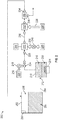
- FIG. 2 is a schematic illustration of a flammability reduction or inerting system 200 utilizing a catalytic reaction to produce inert gas in accordance with an embodiment of the present disclosure.
- the inerting system 200 includes a fuel tank 202 having fuel 204 therein. As the fuel 204 is consumed during operation of one or more engines, an ullage space 206 forms within the fuel tank 202. To reduce flammability risks associated with vaporized fuel that may form within the ullage space 206, an inert gas can be generated and fed into the ullage space 206.
- an inerting fuel 208 can be extracted from the fuel tank 202 and into an evaporator container 210.
- the amount of fuel 204 that is extracted into the evaporator container 210 i.e., the amount of inerting fuel 208) can be controlled by an evaporator container valve 212, such as a float valve.
- the inerting fuel 208 which may be in liquid form when pulled from the fuel tank 202, can be vaporized within the evaporator container 210 using a heater 214, such as an electric heater, to generate a first reactant 216.
- the first reactant 216 is a vaporized portion of the inerting fuel 208 located within the evaporator container 210.
- the first reactant 216 is mixed with a second reactant 218 which is sourced from a second reactant source 220.
- the second reactant 218 is air containing oxygen that is catalyzed with the first reactant 216 to generate an inert gas to be supplied into the ullage space 206 of the fuel tank 202.
- the second reactant 218 can come from any source on an aircraft that is at a pressure greater than ambient, including, but not limited to bleed air from an engine, cabin air, high pressure air extracted or bled from an engine, etc. (i.e., any second reactant source 220 can take any number of configurations and/or arrangements).
- the first reactant 216 within the evaporator container 210 and the second reactant 218 can be directed into a catalytic reactor 222 by and/or through a mixer 224, which, in some embodiments, may be an ejector or jet pump.
- the mixer 224 will mix the first and second reactants 216, 218 into a mixed air stream 225.
- the catalytic reactor 222 can be temperature controlled to ensure a desired chemical reaction efficiency such that an inert gas can be efficiently produced by the inerting system 200 from the mixed air stream 225. Accordingly, cooling air 226 can be provided to extract heat from the catalytic reactor 222 to achieve a desired thermal condition for the chemical reaction within the catalytic reactor 222.
- the cooling air 226 can be sourced from a cool air source 228.
- a catalyzed mixture 230 leaves the catalytic reactor 222 and is passed through a heat exchanger 232.
- the heat exchanger 232 operates as a condenser on the catalyzed mixture 230 to separate out an inert gas 234 and a byproduct 236.
- a cooling air is supplied into the heat exchanger 232 to achieve the condensing functionality.
- a cooling air 226 can be sourced from the same cool air source 228 as that provided to the catalytic reactor 222, although in other embodiments the cool air sources for the two components may be different.
- the byproduct 236 may be liquid water or water vapor, and thus in the present configuration shown in FIG. 2 , a water separator 238 is provided downstream of the heat exchanger 232 to extract the liquid water or water vapor from the catalyzed mixture 230, thus leaving only the inert gas 234 to be provided to the ullage space 206 of the fuel tank 202.
- the inerting system 200 can include additional components including, but not limited to, a fan, a flame arrestor, and a controller 244. Various other components can be included without departing from the scope of the present disclosure. In some embodiments, the inerting system 200 can supply inert gas to multiple fuel tanks on an aircraft.
- Catalysts are subject to deactivation due to the presence of certain elements (e.g., sulfur) in the feed gas, including the fuel. Monitoring catalyst deactivation can be useful to determine when catalyst regeneration or replacement is necessary or when catalyst regeneration or replacement should be performed. At least one temperature sensor can be used in the catalytic reactor to measure catalyst activity (e.g, in catalytic reactor 222 of FIG. 2 ).
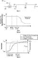
- FIG. 3 shows a simplified version of a catalytic system 300 according to one embodiment.
- the system includes a catalytic reactor 302.
- the catalytic reactor 302 induces a chemical reaction between oxygen (second reactant 308) and fuel vapor (fuel source, first reactant 306) to produce carbon dioxide and water in the vapor phase.
- the source of the second reactant 308 e.g., oxygen
- the fuel vapor (first reactant 306) is received either directly or indirectly from the aircraft fuel tank (e.g., fuel tank 202 in FIG. 2 ).
- the first and second reactants 306, 308, can be mixed in a mixing chamber 304 to form a combined flow 318 before being provided to the inlet 314 of the primary catalytic reactor 302.
- the catalyst is located in the catalytic reactor 302 and may be disposed on a support.
- the catalyst surface is defined as the surface of the catalyst/support combination.
- the system 300 can include one or more temperature sensors 312.
- the temperature sensor can be located in the flow path, on the catalyst surface or in both locations. In any case the temperature sensor is located within the catalytic reactor at a location between the inlet 314 and the outlet 316 of the reactor. The temperature sensor may be located closer to the outlet than the inlet. In some embodiments multiple adjacent sensors are used for redundancy against failure. In some embodiments the temperature sensor comprises a thermocouple. As shown, the system 300 includes one temperature sensor. This is not meant to be limiting and other numbers of sensors could be provided. The temperature sensor is in operable communication with controller 244. By comparing the readings of the sensor(s) to a threshold temperature, a status of the catalyst in the reactor 302 can be determined. Such a status can be used for scheduling maintenance and/or scheduling catalyst regeneration timing.
- a catalyst deactivation model can be created for the catalytic reactor 302. For example, when multiple temperature sensors are used and located at regular intervals along the flow path the progression of the temperature decrease can have predictive value, especially when different fuel sources or different air sources, having different deactivating elements, can affect the activity of the catalyst.
- FIG. 4 shows a graph of catalytic temperature over time at a single location. Near the end of catalyst life the temperature decreases and when the temperature falls below the temperature threshold the controller recognizes the need for replacement and/or regeneration, or for scheduling of maintenance.
- the threshold temperature may be defined in relationship to the reaction temperature. For example, the threshold temperature may be 80% of the reaction temperature, or 70% of the reaction temperature, or 60% of the reaction temperature. In some embodiments the temperature sensor is located closer to the outlet than the inlet and the threshold temperature is 80%, 70%, or 60% of the reaction temperature. In some embodiments the temperature sensor is located closer to the inlet than the outlet and the threshold temperature is 60%, 50%, or 40% of the reaction temperature.
- the reaction temperature is defined as the maximum temperature of the measured feature. For example, if the reaction mixture temperature (the gas temperature) is being measured then the reaction temperature is the maximum temperature of the reaction mixture. If the catalyst surface is being measured then the reaction temperature is the maximum temperature of the catalyst surface.
- a catalyzed reaction in a catalyst bed can be either kinetically limited or mass transfer limited.
- the type of limitation generally depends on the form of the catalyst/catalyst support system.
- the catalyst bed comprises pellets and/or screens the catalyzed reaction is typically kinetically limited.
- the temperature of the reaction mixture (the gas temperature) is typically quite similar to the temperature of the catalyst surface throughout the reaction.
- the catalyst bed comprises a monolithic honeycomb the catalyzed reaction is typically mass transfer limited and the temperature of the catalyst surface increases much more rapidly than the reaction mixture although as the reaction progresses the reaction mixture temperature approaches the temperature of the catalyst surface.
- FIG. 5 is a graph showing the temperature changes and catalytic conversion percentage for a mass transfer limited catalyzed reaction. As can be seen from the graph the catalyst surface temperature increase much more quickly than the gas temperature (reaction mixture temperature). The catalytic conversion closely tracks the gas temperature.
- temperature sensor quantity may be made depending on a number of factors. These factors include whether the reaction is mass transfer limited or kinetically limited, the pattern of use (long engine run times vs. short engine run times), and the desired amount of warning before maintenance is required.
Landscapes
- Engineering & Computer Science (AREA)
- Chemical & Material Sciences (AREA)
- Chemical Kinetics & Catalysis (AREA)
- Aviation & Aerospace Engineering (AREA)
- Organic Chemistry (AREA)
- Physics & Mathematics (AREA)
- General Physics & Mathematics (AREA)
- Environmental & Geological Engineering (AREA)
- Manufacturing & Machinery (AREA)
- Transportation (AREA)
- Oil, Petroleum & Natural Gas (AREA)
- General Chemical & Material Sciences (AREA)
- Analytical Chemistry (AREA)
- Biomedical Technology (AREA)
- Health & Medical Sciences (AREA)
- Physical Or Chemical Processes And Apparatus (AREA)
- Devices And Processes Conducted In The Presence Of Fluids And Solid Particles (AREA)
Claims (10)
- Inertisierungssystem für Kraftstofftanks, umfassend:
einen katalytischen Reaktor (222, 302), der einen Einlass (314), einen Auslass (316), einen reaktiven Strömungsweg zwischen dem Einlass und dem Auslass, einen Katalysator auf dem reaktiven Strömungsweg, einen Temperatursensor (312), der sich zwischen dem Einlass und dem Auslass befindet und in Wirkkommunikation mit einer Steuerung (244) steht, und einen Wärmetauscher (232) umfasst, der bei Verwendung zwischen dem Auslass und einem Leerraum eines Kraftstofftanks angeordnet ist, wobei der katalytische Reaktor angeordnet ist, um Kraftstoffdampf (216) von einer Kraftstoffquelle (210) und Luft (218) von einer Luftquelle (220) zu empfangen, die gemischt werden, um eine kombinierte Strömung auszubilden, und um auf die kombinierte Strömung entlang des reaktiven Strömungswegs zu reagieren, um ein katalysiertes Gemisch zu erzeugen, das ein Inertgas umfasst, wobei das katalysierte Gemisch in dem Wärmetauscher in das Inertgas und ein Nebenprodukt aufgespalten wird, wobei dem Leerraum des Kraftstofftanks das Inertgas bereitgestellt werden kann. - Inertisierungssystem für Kraftstofftanks nach Anspruch 1, wobei sich der Temperatursensor in dem reaktiven Strömungsweg befindet.
- Inertisierungssystem für Kraftstofftanks nach Anspruch 1, wobei sich der Temperatursensor auf der Katalysatoroberfläche befindet.
- Inertisierungssystem für Kraftstofftanks nach Anspruch 1, 2 oder 3, wobei der katalytische Reaktor einen zusätzlichen Temperatursensor umfasst.
- Inertisierungssystem für Kraftstofftanks nach einem der Ansprüche 1 oder 4, wobei sich der Temperatursensor näher an dem Auslass als an dem Einlass befindet.
- Verfahren zur Verwaltung der Wartung des Inertisierungssystems für Kraftstofftanks nach einem der Ansprüche 1 bis 5, umfassend Reagieren eines Gemischs von Kraftstoffdampf (216) und Luft (218) bei Vorhandensein des Katalysators bei einer Reaktionstemperatur; Messen einer Temperatur der Katalysatoroberfläche oder einer Temperatur des Gemischs an einer Stelle zwischen dem Einlass (314) und dem Auslass (316) des katalytischen Reaktors (222, 302); Vergleichen der gemessenen Temperatur mit einer Schwellentemperatur; und Planen einer Wartung des Katalysators, wenn die gemessene Temperatur geringer als die Schwellentemperatur ist.
- Verfahren nach Anspruch 6, wobei die Temperatur an einer Stelle näher an dem Einlass als an dem Auslass gemessen wird.
- Verfahren nach Anspruch 7, wobei die Schwellentemperatur 60 % der Reaktionstemperatur ist; oder
wobei die Schwellentemperatur 50 % der Reaktionstemperatur ist. - Verfahren nach Anspruch 6, ferner umfassend Messen einer Temperatur des Katalysators an einer zweiten Stelle zwischen dem Einlass und dem Auslass.
- Verfahren nach Anspruch 6, wobei die Temperatur des Gemischs gemessen wird und die Schwellentemperatur 80 % der Reaktionstemperatur ist; oderwobei die Schwellentemperatur 70 % der Reaktionstemperatur ist; oderwobei die Schwellentemperatur 60 % der Reaktionstemperatur ist.
Applications Claiming Priority (1)
| Application Number | Priority Date | Filing Date | Title |
|---|---|---|---|
| US16/213,315 US20200180775A1 (en) | 2018-12-07 | 2018-12-07 | Catalyst deactivation monitoring of catalytic inerting system |
Publications (2)
| Publication Number | Publication Date |
|---|---|
| EP3663208A1 EP3663208A1 (de) | 2020-06-10 |
| EP3663208B1 true EP3663208B1 (de) | 2021-11-17 |
Family
ID=68771440
Family Applications (1)
| Application Number | Title | Priority Date | Filing Date |
|---|---|---|---|
| EP19213436.9A Active EP3663208B1 (de) | 2018-12-07 | 2019-12-04 | Katalysatordeaktivierungsüberwachung eines katalytischen inertisierungssystems |
Country Status (2)
| Country | Link |
|---|---|
| US (1) | US20200180775A1 (de) |
| EP (1) | EP3663208B1 (de) |
Families Citing this family (1)
| Publication number | Priority date | Publication date | Assignee | Title |
|---|---|---|---|---|
| US11346264B2 (en) * | 2019-08-29 | 2022-05-31 | Cummins Emission Solutions Inc. | Systems and methods for controlling exhaust gas aftertreatment sensor systems |
Family Cites Families (6)
| Publication number | Priority date | Publication date | Assignee | Title |
|---|---|---|---|---|
| JP3398862B2 (ja) * | 2000-07-06 | 2003-04-21 | 本田技研工業株式会社 | 燃料蒸発器の暖機方法 |
| DE10054846A1 (de) * | 2000-11-04 | 2002-08-08 | Xcellsis Gmbh | Verfahren zum Betreiben einer Gaserzeugungsvorrichtung und Gaserzeugungsvorrichtung |
| JP2003288934A (ja) * | 2002-01-23 | 2003-10-10 | Nissan Motor Co Ltd | 燃料電池用燃料改質装置 |
| US20030194363A1 (en) * | 2002-04-12 | 2003-10-16 | Koripella Chowdary Ramesh | Chemical reactor and fuel processor utilizing ceramic technology |
| US7101175B2 (en) * | 2003-04-04 | 2006-09-05 | Texaco Inc. | Anode tailgas oxidizer |
| FR2860455B1 (fr) * | 2003-10-03 | 2007-10-26 | Renault Sa | Systeme de production d'hydrogene a bord d'un vehicule en utilisant la deshydrogenation de composes organiques |
-
2018
- 2018-12-07 US US16/213,315 patent/US20200180775A1/en not_active Abandoned
-
2019
- 2019-12-04 EP EP19213436.9A patent/EP3663208B1/de active Active
Also Published As
| Publication number | Publication date |
|---|---|
| US20200180775A1 (en) | 2020-06-11 |
| EP3663208A1 (de) | 2020-06-10 |
Similar Documents
| Publication | Publication Date | Title |
|---|---|---|
| EP3279092A1 (de) | Katalytische kraftstofftankinertisierungsvorrichtung für ein flugzeug | |
| EP3587276A1 (de) | Katalytisches kraftstofftankinertisierungssystem | |
| US20180222598A1 (en) | Catalytic fuel tank inerting apparatus for aircraft | |
| US10745145B2 (en) | Contaminant removal for catalytic fuel tank inerting system | |
| US20210047048A1 (en) | Catalyst decay monitoring of catalytic inerting system | |
| EP3501625A1 (de) | Katalytisches kraftstofftankinertisierungssystem | |
| EP3663208B1 (de) | Katalysatordeaktivierungsüberwachung eines katalytischen inertisierungssystems | |
| EP3360790B1 (de) | Apparartur mit einem katalysator zum inertisieren von kraftstofftanks in flugzeugen | |
| EP3542888A1 (de) | Temperatursensoren zur vorhersage der lebensdauer einer katalytischen inertisierung | |
| EP3666661B1 (de) | Vorrichtung zur katalytischen kraftstofftankinertisierung für flugzeug | |
| EP3666660B1 (de) | Vorrichtung zur katalytischen kraftstofftankinertisierung für flugzeug | |
| EP3501992B1 (de) | Kraftstofftankinertisierungssystem | |
| US10479522B2 (en) | Internal recycle reactor for catalytic inerting | |
| US10994860B2 (en) | Catalytic fuel tank inerting system | |
| US11745892B2 (en) | Catalytic fuel tank inerting apparatus for aircraft | |
| EP3666662B1 (de) | Vorrichtung zur katalytischen kraftstofftankinertisierung für flugzeug | |
| EP3718901B1 (de) | System zur katalytischen kraftstofftankinertisierung für flugzeug | |
| EP3868668B1 (de) | Katalytisches kraftstofftankinertisierungssystem |
Legal Events
| Date | Code | Title | Description |
|---|---|---|---|
| PUAI | Public reference made under article 153(3) epc to a published international application that has entered the european phase |
Free format text: ORIGINAL CODE: 0009012 |
|
| STAA | Information on the status of an ep patent application or granted ep patent |
Free format text: STATUS: THE APPLICATION HAS BEEN PUBLISHED |
|
| AK | Designated contracting states |
Kind code of ref document: A1 Designated state(s): AL AT BE BG CH CY CZ DE DK EE ES FI FR GB GR HR HU IE IS IT LI LT LU LV MC MK MT NL NO PL PT RO RS SE SI SK SM TR |
|
| AX | Request for extension of the european patent |
Extension state: BA ME |
|
| STAA | Information on the status of an ep patent application or granted ep patent |
Free format text: STATUS: REQUEST FOR EXAMINATION WAS MADE |
|
| STAA | Information on the status of an ep patent application or granted ep patent |
Free format text: STATUS: EXAMINATION IS IN PROGRESS |
|
| 17P | Request for examination filed |
Effective date: 20201209 |
|
| RBV | Designated contracting states (corrected) |
Designated state(s): AL AT BE BG CH CY CZ DE DK EE ES FI FR GB GR HR HU IE IS IT LI LT LU LV MC MK MT NL NO PL PT RO RS SE SI SK SM TR |
|
| 17Q | First examination report despatched |
Effective date: 20210112 |
|
| GRAP | Despatch of communication of intention to grant a patent |
Free format text: ORIGINAL CODE: EPIDOSNIGR1 |
|
| STAA | Information on the status of an ep patent application or granted ep patent |
Free format text: STATUS: GRANT OF PATENT IS INTENDED |
|
| INTG | Intention to grant announced |
Effective date: 20210616 |
|
| GRAS | Grant fee paid |
Free format text: ORIGINAL CODE: EPIDOSNIGR3 |
|
| GRAA | (expected) grant |
Free format text: ORIGINAL CODE: 0009210 |
|
| STAA | Information on the status of an ep patent application or granted ep patent |
Free format text: STATUS: THE PATENT HAS BEEN GRANTED |
|
| AK | Designated contracting states |
Kind code of ref document: B1 Designated state(s): AL AT BE BG CH CY CZ DE DK EE ES FI FR GB GR HR HU IE IS IT LI LT LU LV MC MK MT NL NO PL PT RO RS SE SI SK SM TR |
|
| REG | Reference to a national code |
Ref country code: GB Ref legal event code: FG4D |
|
| REG | Reference to a national code |
Ref country code: DE Ref legal event code: R096 Ref document number: 602019009348 Country of ref document: DE |
|
| REG | Reference to a national code |
Ref country code: IE Ref legal event code: FG4D |
|
| REG | Reference to a national code |
Ref country code: AT Ref legal event code: REF Ref document number: 1447862 Country of ref document: AT Kind code of ref document: T Effective date: 20211215 |
|
| REG | Reference to a national code |
Ref country code: LT Ref legal event code: MG9D |
|
| REG | Reference to a national code |
Ref country code: NL Ref legal event code: MP Effective date: 20211117 |
|
| REG | Reference to a national code |
Ref country code: AT Ref legal event code: MK05 Ref document number: 1447862 Country of ref document: AT Kind code of ref document: T Effective date: 20211117 |
|
| PG25 | Lapsed in a contracting state [announced via postgrant information from national office to epo] |
Ref country code: RS Free format text: LAPSE BECAUSE OF FAILURE TO SUBMIT A TRANSLATION OF THE DESCRIPTION OR TO PAY THE FEE WITHIN THE PRESCRIBED TIME-LIMIT Effective date: 20211117 Ref country code: LT Free format text: LAPSE BECAUSE OF FAILURE TO SUBMIT A TRANSLATION OF THE DESCRIPTION OR TO PAY THE FEE WITHIN THE PRESCRIBED TIME-LIMIT Effective date: 20211117 Ref country code: FI Free format text: LAPSE BECAUSE OF FAILURE TO SUBMIT A TRANSLATION OF THE DESCRIPTION OR TO PAY THE FEE WITHIN THE PRESCRIBED TIME-LIMIT Effective date: 20211117 Ref country code: BG Free format text: LAPSE BECAUSE OF FAILURE TO SUBMIT A TRANSLATION OF THE DESCRIPTION OR TO PAY THE FEE WITHIN THE PRESCRIBED TIME-LIMIT Effective date: 20220217 Ref country code: AT Free format text: LAPSE BECAUSE OF FAILURE TO SUBMIT A TRANSLATION OF THE DESCRIPTION OR TO PAY THE FEE WITHIN THE PRESCRIBED TIME-LIMIT Effective date: 20211117 |
|
| PG25 | Lapsed in a contracting state [announced via postgrant information from national office to epo] |
Ref country code: IS Free format text: LAPSE BECAUSE OF FAILURE TO SUBMIT A TRANSLATION OF THE DESCRIPTION OR TO PAY THE FEE WITHIN THE PRESCRIBED TIME-LIMIT Effective date: 20220317 Ref country code: SE Free format text: LAPSE BECAUSE OF FAILURE TO SUBMIT A TRANSLATION OF THE DESCRIPTION OR TO PAY THE FEE WITHIN THE PRESCRIBED TIME-LIMIT Effective date: 20211117 Ref country code: PT Free format text: LAPSE BECAUSE OF FAILURE TO SUBMIT A TRANSLATION OF THE DESCRIPTION OR TO PAY THE FEE WITHIN THE PRESCRIBED TIME-LIMIT Effective date: 20220317 Ref country code: PL Free format text: LAPSE BECAUSE OF FAILURE TO SUBMIT A TRANSLATION OF THE DESCRIPTION OR TO PAY THE FEE WITHIN THE PRESCRIBED TIME-LIMIT Effective date: 20211117 Ref country code: NO Free format text: LAPSE BECAUSE OF FAILURE TO SUBMIT A TRANSLATION OF THE DESCRIPTION OR TO PAY THE FEE WITHIN THE PRESCRIBED TIME-LIMIT Effective date: 20220217 Ref country code: NL Free format text: LAPSE BECAUSE OF FAILURE TO SUBMIT A TRANSLATION OF THE DESCRIPTION OR TO PAY THE FEE WITHIN THE PRESCRIBED TIME-LIMIT Effective date: 20211117 Ref country code: LV Free format text: LAPSE BECAUSE OF FAILURE TO SUBMIT A TRANSLATION OF THE DESCRIPTION OR TO PAY THE FEE WITHIN THE PRESCRIBED TIME-LIMIT Effective date: 20211117 Ref country code: HR Free format text: LAPSE BECAUSE OF FAILURE TO SUBMIT A TRANSLATION OF THE DESCRIPTION OR TO PAY THE FEE WITHIN THE PRESCRIBED TIME-LIMIT Effective date: 20211117 Ref country code: GR Free format text: LAPSE BECAUSE OF FAILURE TO SUBMIT A TRANSLATION OF THE DESCRIPTION OR TO PAY THE FEE WITHIN THE PRESCRIBED TIME-LIMIT Effective date: 20220218 Ref country code: ES Free format text: LAPSE BECAUSE OF FAILURE TO SUBMIT A TRANSLATION OF THE DESCRIPTION OR TO PAY THE FEE WITHIN THE PRESCRIBED TIME-LIMIT Effective date: 20211117 |
|
| PG25 | Lapsed in a contracting state [announced via postgrant information from national office to epo] |
Ref country code: SM Free format text: LAPSE BECAUSE OF FAILURE TO SUBMIT A TRANSLATION OF THE DESCRIPTION OR TO PAY THE FEE WITHIN THE PRESCRIBED TIME-LIMIT Effective date: 20211117 Ref country code: SK Free format text: LAPSE BECAUSE OF FAILURE TO SUBMIT A TRANSLATION OF THE DESCRIPTION OR TO PAY THE FEE WITHIN THE PRESCRIBED TIME-LIMIT Effective date: 20211117 Ref country code: RO Free format text: LAPSE BECAUSE OF FAILURE TO SUBMIT A TRANSLATION OF THE DESCRIPTION OR TO PAY THE FEE WITHIN THE PRESCRIBED TIME-LIMIT Effective date: 20211117 Ref country code: EE Free format text: LAPSE BECAUSE OF FAILURE TO SUBMIT A TRANSLATION OF THE DESCRIPTION OR TO PAY THE FEE WITHIN THE PRESCRIBED TIME-LIMIT Effective date: 20211117 Ref country code: DK Free format text: LAPSE BECAUSE OF FAILURE TO SUBMIT A TRANSLATION OF THE DESCRIPTION OR TO PAY THE FEE WITHIN THE PRESCRIBED TIME-LIMIT Effective date: 20211117 Ref country code: CZ Free format text: LAPSE BECAUSE OF FAILURE TO SUBMIT A TRANSLATION OF THE DESCRIPTION OR TO PAY THE FEE WITHIN THE PRESCRIBED TIME-LIMIT Effective date: 20211117 |
|
| REG | Reference to a national code |
Ref country code: DE Ref legal event code: R097 Ref document number: 602019009348 Country of ref document: DE |
|
| PG25 | Lapsed in a contracting state [announced via postgrant information from national office to epo] |
Ref country code: MC Free format text: LAPSE BECAUSE OF FAILURE TO SUBMIT A TRANSLATION OF THE DESCRIPTION OR TO PAY THE FEE WITHIN THE PRESCRIBED TIME-LIMIT Effective date: 20211117 |
|
| PLBE | No opposition filed within time limit |
Free format text: ORIGINAL CODE: 0009261 |
|
| STAA | Information on the status of an ep patent application or granted ep patent |
Free format text: STATUS: NO OPPOSITION FILED WITHIN TIME LIMIT |
|
| REG | Reference to a national code |
Ref country code: BE Ref legal event code: MM Effective date: 20211231 |
|
| 26N | No opposition filed |
Effective date: 20220818 |
|
| PG25 | Lapsed in a contracting state [announced via postgrant information from national office to epo] |
Ref country code: LU Free format text: LAPSE BECAUSE OF NON-PAYMENT OF DUE FEES Effective date: 20211204 Ref country code: IE Free format text: LAPSE BECAUSE OF NON-PAYMENT OF DUE FEES Effective date: 20211204 Ref country code: AL Free format text: LAPSE BECAUSE OF FAILURE TO SUBMIT A TRANSLATION OF THE DESCRIPTION OR TO PAY THE FEE WITHIN THE PRESCRIBED TIME-LIMIT Effective date: 20211117 |
|
| PG25 | Lapsed in a contracting state [announced via postgrant information from national office to epo] |
Ref country code: SI Free format text: LAPSE BECAUSE OF FAILURE TO SUBMIT A TRANSLATION OF THE DESCRIPTION OR TO PAY THE FEE WITHIN THE PRESCRIBED TIME-LIMIT Effective date: 20211117 Ref country code: BE Free format text: LAPSE BECAUSE OF NON-PAYMENT OF DUE FEES Effective date: 20211231 |
|
| PG25 | Lapsed in a contracting state [announced via postgrant information from national office to epo] |
Ref country code: IT Free format text: LAPSE BECAUSE OF FAILURE TO SUBMIT A TRANSLATION OF THE DESCRIPTION OR TO PAY THE FEE WITHIN THE PRESCRIBED TIME-LIMIT Effective date: 20211117 |
|
| PG25 | Lapsed in a contracting state [announced via postgrant information from national office to epo] |
Ref country code: CY Free format text: LAPSE BECAUSE OF FAILURE TO SUBMIT A TRANSLATION OF THE DESCRIPTION OR TO PAY THE FEE WITHIN THE PRESCRIBED TIME-LIMIT Effective date: 20211117 |
|
| P01 | Opt-out of the competence of the unified patent court (upc) registered |
Effective date: 20230603 |
|
| PG25 | Lapsed in a contracting state [announced via postgrant information from national office to epo] |
Ref country code: HU Free format text: LAPSE BECAUSE OF FAILURE TO SUBMIT A TRANSLATION OF THE DESCRIPTION OR TO PAY THE FEE WITHIN THE PRESCRIBED TIME-LIMIT; INVALID AB INITIO Effective date: 20191204 |
|
| REG | Reference to a national code |
Ref country code: CH Ref legal event code: PL |
|
| PG25 | Lapsed in a contracting state [announced via postgrant information from national office to epo] |
Ref country code: LI Free format text: LAPSE BECAUSE OF NON-PAYMENT OF DUE FEES Effective date: 20221231 Ref country code: CH Free format text: LAPSE BECAUSE OF NON-PAYMENT OF DUE FEES Effective date: 20221231 |
|
| PG25 | Lapsed in a contracting state [announced via postgrant information from national office to epo] |
Ref country code: MK Free format text: LAPSE BECAUSE OF FAILURE TO SUBMIT A TRANSLATION OF THE DESCRIPTION OR TO PAY THE FEE WITHIN THE PRESCRIBED TIME-LIMIT Effective date: 20211117 |
|
| PG25 | Lapsed in a contracting state [announced via postgrant information from national office to epo] |
Ref country code: TR Free format text: LAPSE BECAUSE OF FAILURE TO SUBMIT A TRANSLATION OF THE DESCRIPTION OR TO PAY THE FEE WITHIN THE PRESCRIBED TIME-LIMIT Effective date: 20211117 |
|
| PG25 | Lapsed in a contracting state [announced via postgrant information from national office to epo] |
Ref country code: MT Free format text: LAPSE BECAUSE OF FAILURE TO SUBMIT A TRANSLATION OF THE DESCRIPTION OR TO PAY THE FEE WITHIN THE PRESCRIBED TIME-LIMIT Effective date: 20211117 |
|
| PGFP | Annual fee paid to national office [announced via postgrant information from national office to epo] |
Ref country code: DE Payment date: 20241121 Year of fee payment: 6 |
|
| PGFP | Annual fee paid to national office [announced via postgrant information from national office to epo] |
Ref country code: GB Payment date: 20241122 Year of fee payment: 6 |
|
| PGFP | Annual fee paid to national office [announced via postgrant information from national office to epo] |
Ref country code: FR Payment date: 20241121 Year of fee payment: 6 |