EP3663195B1 - Procede d'asservissement en vitesse d'un dispositif d'entrainement en rotation des roues d'un aeronef - Google Patents
Procede d'asservissement en vitesse d'un dispositif d'entrainement en rotation des roues d'un aeronef Download PDFInfo
- Publication number
- EP3663195B1 EP3663195B1 EP19213631.5A EP19213631A EP3663195B1 EP 3663195 B1 EP3663195 B1 EP 3663195B1 EP 19213631 A EP19213631 A EP 19213631A EP 3663195 B1 EP3663195 B1 EP 3663195B1
- Authority
- EP
- European Patent Office
- Prior art keywords
- speed
- aircraft
- landing gear
- wheels
- main landing
- Prior art date
- Legal status (The legal status is an assumption and is not a legal conclusion. Google has not performed a legal analysis and makes no representation as to the accuracy of the status listed.)
- Active
Links
Images
Classifications
-
- B—PERFORMING OPERATIONS; TRANSPORTING
- B64—AIRCRAFT; AVIATION; COSMONAUTICS
- B64C—AEROPLANES; HELICOPTERS
- B64C25/00—Alighting gear
- B64C25/32—Alighting gear characterised by elements which contact the ground or similar surface
- B64C25/405—Powered wheels, e.g. for taxing
-
- B—PERFORMING OPERATIONS; TRANSPORTING
- B64—AIRCRAFT; AVIATION; COSMONAUTICS
- B64C—AEROPLANES; HELICOPTERS
- B64C25/00—Alighting gear
- B64C25/32—Alighting gear characterised by elements which contact the ground or similar surface
- B64C25/50—Steerable undercarriages; Shimmy-damping
-
- B—PERFORMING OPERATIONS; TRANSPORTING
- B60—VEHICLES IN GENERAL
- B60T—VEHICLE BRAKE CONTROL SYSTEMS OR PARTS THEREOF; BRAKE CONTROL SYSTEMS OR PARTS THEREOF, IN GENERAL; ARRANGEMENT OF BRAKING ELEMENTS ON VEHICLES IN GENERAL; PORTABLE DEVICES FOR PREVENTING UNWANTED MOVEMENT OF VEHICLES; VEHICLE MODIFICATIONS TO FACILITATE COOLING OF BRAKES
- B60T8/00—Arrangements for adjusting wheel-braking force to meet varying vehicular or ground-surface conditions, e.g. limiting or varying distribution of braking force
- B60T8/17—Using electrical or electronic regulation means to control braking
- B60T8/1701—Braking or traction control means specially adapted for particular types of vehicles
- B60T8/1703—Braking or traction control means specially adapted for particular types of vehicles for aircrafts
-
- B—PERFORMING OPERATIONS; TRANSPORTING
- B60—VEHICLES IN GENERAL
- B60T—VEHICLE BRAKE CONTROL SYSTEMS OR PARTS THEREOF; BRAKE CONTROL SYSTEMS OR PARTS THEREOF, IN GENERAL; ARRANGEMENT OF BRAKING ELEMENTS ON VEHICLES IN GENERAL; PORTABLE DEVICES FOR PREVENTING UNWANTED MOVEMENT OF VEHICLES; VEHICLE MODIFICATIONS TO FACILITATE COOLING OF BRAKES
- B60T8/00—Arrangements for adjusting wheel-braking force to meet varying vehicular or ground-surface conditions, e.g. limiting or varying distribution of braking force
- B60T8/17—Using electrical or electronic regulation means to control braking
- B60T8/1755—Brake regulation specially adapted to control the stability of the vehicle, e.g. taking into account yaw rate or transverse acceleration in a curve
-
- B—PERFORMING OPERATIONS; TRANSPORTING
- B64—AIRCRAFT; AVIATION; COSMONAUTICS
- B64C—AEROPLANES; HELICOPTERS
- B64C25/00—Alighting gear
- B64C25/32—Alighting gear characterised by elements which contact the ground or similar surface
- B64C25/34—Alighting gear characterised by elements which contact the ground or similar surface wheeled type, e.g. multi-wheeled bogies
-
- B—PERFORMING OPERATIONS; TRANSPORTING
- B60—VEHICLES IN GENERAL
- B60T—VEHICLE BRAKE CONTROL SYSTEMS OR PARTS THEREOF; BRAKE CONTROL SYSTEMS OR PARTS THEREOF, IN GENERAL; ARRANGEMENT OF BRAKING ELEMENTS ON VEHICLES IN GENERAL; PORTABLE DEVICES FOR PREVENTING UNWANTED MOVEMENT OF VEHICLES; VEHICLE MODIFICATIONS TO FACILITATE COOLING OF BRAKES
- B60T2201/00—Particular use of vehicle brake systems; Special systems using also the brakes; Special software modules within the brake system controller
- B60T2201/16—Curve braking control, e.g. turn control within ABS control algorithm
-
- Y—GENERAL TAGGING OF NEW TECHNOLOGICAL DEVELOPMENTS; GENERAL TAGGING OF CROSS-SECTIONAL TECHNOLOGIES SPANNING OVER SEVERAL SECTIONS OF THE IPC; TECHNICAL SUBJECTS COVERED BY FORMER USPC CROSS-REFERENCE ART COLLECTIONS [XRACs] AND DIGESTS
- Y02—TECHNOLOGIES OR APPLICATIONS FOR MITIGATION OR ADAPTATION AGAINST CLIMATE CHANGE
- Y02T—CLIMATE CHANGE MITIGATION TECHNOLOGIES RELATED TO TRANSPORTATION
- Y02T50/00—Aeronautics or air transport
- Y02T50/80—Energy efficient operational measures, e.g. ground operations or mission management
Definitions
- the invention relates to a method for controlling the speed of a device for driving the rotation of the wheels of an aircraft.
- the drive device comprises drive actuators adapted to drive wheels of the aircraft in rotation, when placed in a position of engagement with the wheels.
- On an aircraft comprising two main landing gears such as for example the AIRBUS A320, drive devices have been proposed comprising on each of the main landing gears at least one drive actuator adapted to drive at least one wheel in rotation.
- Various strategies for controlling these training devices have been proposed, including strategies for controlling the speed of the aircraft to a speed setpoint generated by the pilot.
- the document WO 2006/078322 A2 discloses a speed control of an auxiliary undercarriage.
- Such control requires measuring the speed of the aircraft, or at least making an estimate.
- We can for example use the speed measurement given by the inertial unit of the aircraft, a speed estimate given by an on-board GPS, or even an average of the circumferential speeds of the wheels driven by the actuators of the drive device, these speeds being deduced directly from the rotational speed of the motors of the drive actuators or from the rotational speed of the driven wheels.
- the speed thus estimated is approximately that of the center of gravity of the aircraft.
- the invention aims to propose a method for controlling the speed of a device for driving the rotation of the wheels of an aircraft, reducing this sensation of racing felt by pilots during turns.
- a method of controlling the speed of a device for driving the wheels of an aircraft in rotation comprising the step of regulating a speed of the aircraft in accordance with a setpoint. of speed generated by the pilot, in which the regulated speed of the aircraft is a measured or estimated speed of a portion of the aircraft located at a front tip of the aircraft.
- the speed at the front end of the aircraft which is typically several meters from the center of gravity of the aircraft, is more representative of the speed perceived by the pilots than the speed at the center. gravity of the device. Drivers no longer have the impression of surging speed during turns.
- the speed to be regulated is an estimate of a circumferential speed of the wheels of an auxiliary undercarriage of the aircraft located under the nose of the aircraft.
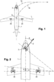
- FIG. 1 illustrates an aircraft 1 making a turn to the right.
- the aircraft is equipped with a left main landing gear 2G and a right main landing gear 2D, and an auxiliary landing gear 3 located at a front tip 4 of the aircraft.
- the auxiliary landing gear is located approximately at the level of the cockpit of the aircraft.
- the cockpit and the auxiliary landing gear are a good ten meters away from an imaginary line L passing through the main landing gear 2G, 2D.
- the center of gravity G of the aircraft is located slightly in front of the imaginary line L.
- the main landing gear 2G, 2D are equipped with a device for driving the rotating wheels, comprising on each of the main landing gear an actuator rotating drive (e.g. outer wheels).
- a control makes it possible to regulate a speed of the aircraft to a speed setpoint generated by the pilot, for example by means of a joystick in the cockpit.
- the drive device and the type of speed control implemented is not the subject of the invention, and can be of any type. For example, we can use a proportional-integral-derivative type feedback loop control.
- the invention aims to reduce this sensation and to do this, proposes to control a speed setpoint generated by the pilot not a speed at the level of the center of gravity, but a speed at the level of the tip before the 'aircraft.
- a speed setpoint generated by the pilot not a speed at the level of the center of gravity, but a speed at the level of the tip before the 'aircraft.
- V vs V G + V D 2
- the speeds V G , V D are the circumferential speeds respectively of a wheel of the left main undercarriage 2G and of a wheel of the right main undercarriage 2D (for example the outer wheels of the two main undercarriages, or the inner wheels of the two main landing gears).
- V c represents the speed of a point at the intersection of the longitudinal axis and the imaginary line L.
- the speeds V G , V D are for example estimated from the rotation speed of the driven wheels which can be measured by tachometers fitted to the main landing gear, or even from the rotational speed of the motor of the actuators of the drive device.
- the angle ⁇ of orientation of the wheels of the auxiliary landing gear it is measured by an angular sensor installed on the auxiliary landing gear.
- the speed to be regulated V can be estimated only by measurements made at the wheels, the actuators of the drive device, or by sensors on the undercarriages themselves, that is to say only by means of landing gear equipment, which avoids any exchange of information with the aircraft's flight control systems to estimate the speed to be regulated V .
- V ⁇ V vs cos ⁇ ⁇
Landscapes
- Engineering & Computer Science (AREA)
- Mechanical Engineering (AREA)
- Aviation & Aerospace Engineering (AREA)
- Transportation (AREA)
- Regulating Braking Force (AREA)
- Control Of Position, Course, Altitude, Or Attitude Of Moving Bodies (AREA)
- Control Of Transmission Device (AREA)
Description
- L'invention concerne un procédé d'asservissement en vitesse d'un dispositif d'entraînement en rotation des roues d'un aéronef.
- On connaît des dispositifs d'entraînement en rotation des roues d'un aéronef permettant de déplacer l'aéronef au sol sans l'aide de ses groupes motopropulseurs. Le dispositif d'entraînement comprend des actionneurs d'entraînement adaptés à entraîner des roues de l'aéronef en rotation, lorsqu'ils sont placés en position d'engagement avec les roues. Sur un aéronef comportant deux atterrisseurs principaux comme par exemple l'AIRBUS A320, il a été proposé des dispositifs d'entraînement comportant sur chacun des atterrisseurs principaux au moins un actionneur d'entraînement adapté à entraîner au moins une roue en rotation. Diverses stratégies de commande de ces dispositifs d'entraînement ont été proposées, dont des stratégies d'asservissement d'une vitesse de l'aéronef à une consigne de vitesse générée par le pilote. Le document
WO 2006/078322 A2 divulgue un asservissement en vitesse d'un atterrisseur auxiliaire . - Un tel asservissement nécessite de mesurer la vitesse de l'aéronef, ou à tout le moins d'en faire une estimation. On peut par exemple utiliser la mesure de vitesse donnée par la centrale inertielle de l'aéronef, une estimation de vitesse donnée par un GPS embarqué, ou encore une moyenne des vitesses circonférentielles des roues entraînées par les actionneurs du dispositif d'entraînement, ces vitesses étant déduites directement de la vitesse de rotation des moteurs des actionneurs d'entraînement ou de la vitesse de rotation des roues entraînées. La vitesse ainsi estimée est sensiblement celle du centre de gravité de l'aéronef.
- Des essais ont permis de montrer que dans certaines circonstances, notamment lors de virages, les pilotes de l'aéronef pouvaient avoir l'impression de subir des vitesses bien plus importantes que la vitesse de consigne.
- L'invention vise à proposer un procédé d'asservissement en vitesse d'un dispositif d'entraînement en rotation des roues d'un aéronef diminuant cette sensation d'emballement ressenti par les pilotes lors de virages.
- En vue de la réalisation de ce but, on propose un procédé d'asservissement en vitesse d'un dispositif d'entraînement en rotation des roues d'un aéronef, comportant l'étape de réguler une vitesse de l'aéronef conformément à une consigne de vitesse générée par le pilote, dans lequel la vitesse de l'aéronef régulée est une vitesse mesurée ou estimée d'une portion de l'aéronef située au niveau d'une pointe avant de l'aéronef.
- Ainsi, lors de virages, la vitesse au niveau de la pointe avant de l'aéronef, qui se situe typiquement à plusieurs mètres du centre de gravité de l'appareil, est plus représentative de la vitesse perçue par les pilotes que la vitesse au centre de gravité de l'appareil. Les pilotes n'ont plus l'impression de l'emballement de la vitesse lors de virages.
- Selon un mode préféré de mise en oeuvre, la vitesse à réguler est une estimation d'une vitesse circonférentielle de roues d'un atterrisseur auxiliaire de l'aéronef situé sous la pointe avant de l'aéronef.
- L'invention sera mieux comprise à la lumière de la description qui suit d'un mode particulier de mise en oeuvre de l'invention, en référence aux figures des dessins annexés, parmi lesquelles :
- la
figure 1 est une vue schématique montrant la trajectoire du centre de gravité d'un aéronef et la trajectoire suivie par les roues de l'atterrisseur auxiliaire ; - la
figure 2 est une vue schématique de dessus d'un aéronef montrant les diverses grandeurs utilisées pour l'estimation de la vitesse longitudinale au niveau des roues de l'atterrisseur auxiliaire. - La
figure 1 illustre un aéronef 1 en train d'effectuer un virage vers la droite. L'aéronef est équipé d'un atterrisseur principal gauche 2G et d'un atterrisseur principal droit 2D, et d'un atterrisseur auxiliaire 3 situé au niveau d'une pointe avant 4 de l'aéronef. On remarquera que l'atterrisseur auxiliaire est situé sensiblement au niveau du cockpit de l'aéronef. Sur un aéronef du type AIRBUS A320, le cockpit et l'atterrisseur auxiliaire sont éloignés d'une bonne dizaine de mètres d'une ligne imaginaire L passant par les atterrisseurs principaux 2G, 2D. Le centre de gravité G de l'aéronef se situe légèrement devant la ligne imaginaire L. Ici, les atterrisseurs principaux 2G, 2D sont équipés d'un dispositif d'entraînement des roues en rotation, comportant sur chacune des atterrisseurs principaux un actionneur d'entraînement en rotation (par exemple des roues extérieures). Un asservissement permet de réguler une vitesse de l'aéronef à une consigne de vitesse générée par le pilote, par exemple au moyen d'une manette dans le cockpit. Le dispositif d'entraînement et le type d'asservissement en vitesse mis en œuvre n'est pas l'objet de l'invention, et peuvent être de tout type. On peut par exemple utiliser un asservissement de type proportionnel-intégral-dérivé à boucle de rétroaction. - On a illustré la trajectoire TG du centre de gravité G, ainsi que la trajectoire TA de l'atterrisseur auxiliaire 3 lors d'un virage. On constate que ces trajectoires sont assez différentes, générant des différences non négligeables de vitesses le long de ces deux trajectoires. Si on asservit la vitesse du centre de gravité de l'aéronef à la consigne de vitesse ou la vitesse d'un point proche dudit centre de gravité, comme par exemple le point d'intersection de l'axe longitudinal de l'aéronef avec la ligne imaginaire L, les pilotes, qui sont situés dans la pointe avant de l'aéronef, donc sensiblement au niveau de l'atterrisseur auxiliaire 3, vont avoir l'impression d'un emballement de la vitesse de l'aéronef, notamment lors de virages.
- L'invention a pour but de diminuer cette sensation et pour ce faire, propose d'asservir à une consigne de vitesse générée par le pilote non pas une vitesse au niveau du centre de gravité, mais une vitesse au niveau de la pointe avant de l'aéronef. Pour ce faire, et selon un mode préféré de mise en oeuvre, on estime une vitesse
V au niveau de l'atterrisseur auxiliaire 3, et c'est cette vitesse que l'asservissement régulera conformément à la vitesse de consigne. - Selon un premier mode particulier de mise en oeuvre, on estime la vitesse à réguler
V par la relation :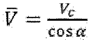
- Où α est l'angle d'orientation des roues de l'atterrisseur auxiliaire, et Vc est la vitesse longitudinale :

- Les vitesses VG, VD sont les vitesses circonférentielles respectivement d'une roue de l'atterrisseur principal gauche 2G et d'une roue de l'atterrisseur principal droit 2D (par exemple les roues extérieures des deux atterrisseurs principaux, ou les roues intérieures des deux atterrisseurs principaux). Vc représente la vitesse d'un point à l'intersection de l'axe longitudinal et de la ligne imaginaire L. Les vitesses VG, VD sont par exemple estimées à partir de la vitesse de rotation des roues entraînées qui peut être mesurée par des tachymètres équipant les atterrisseurs principaux, ou encore à partir de la vitesse de rotation du moteur des actionneurs du dispositif d'entraînement. Quant à l'angle α d'orientation des roues de l'atterrisseur auxiliaire, il est mesuré par un capteur angulaire installé sur l'atterrisseur auxiliaire.
- Ainsi, la vitesse à réguler
V peut être estimée uniquement par des mesures effectuées au niveau des roues, des actionneurs du dispositif d'entraînement, ou par des capteurs sur les atterrisseurs proprement dits, c'est-à-dire uniquement au moyen d'équipements du train d'atterrissage, ce qui évite tout échange d'information avec les systèmes de contrôle de vol de l'aéronef pour estimer la vitesse à régulerV . - Selon un deuxième mode particulier de mise en oeuvre, on estime l'angle α d'orientation des roues de l'atterrisseur auxiliaire au moyen du taux de lacet γ de l'aéronef (c'est-à-dire la vitesse angulaire de l'aéronef autour d'un axe vertical), fourni par exemple par la centrale inertielle de l'aéronef :

- Lx est la distance (mesurée longitudinalement) entre la ligne imaginaire L et l'atterrisseur auxiliaire 3. La vitesse à réguler
V est alors estimée par :
Claims (3)
- Procédé d'asservissement en vitesse d'un dispositif d'entraînement en rotation de roues portées par des atterrisseurs principaux d'un aéronef, comportant l'étape de réguler une vitesse de l'aéronef conformément à une consigne de vitesse générée par le pilote, caractérisé en ce que la vitesse de l'aéronef régulée est une vitesse (
V ) estimée d'une portion de l'aéronef au niveau d'une pointe avant de l'aéronef au moyen de mesures effectuées au niveau des roues portées par les atterrisseurs principaux, d'actionneurs du dispositif d'entraînement, ou par des capteurs sur les atterrisseurs principaux. - Procédé selon la revendication 1, dans lequel la vitesse (
V ) à réguler est estimée au moyen de vitesses circonférentielles (VG, VD ) des roues portées respectivement par un atterrisseur principal gauche et un atterrisseur principale droit, et d'un angle d'orientation (α) de roues portées par un atterrisseur auxiliaire disposé au niveau de la pointe avant de l'aéronef, par

- Procédé selon la revendication 1, dans lequel la vitesse (
V ) à réguler est estimée au moyen de vitesses circonférentielles (VG, VD ) des roues portées respectivement par un atterrisseur principal gauche et un atterrisseur principale droit, et d'un taux de lacet (γ) de l'aéronef, par


Applications Claiming Priority (1)
| Application Number | Priority Date | Filing Date | Title |
|---|---|---|---|
| FR1872387A FR3089494B1 (fr) | 2018-12-05 | 2018-12-05 | Procédé d’asservissement en vitesse d’un dispositif d’entraînement en rotation des roues d’un aéronef |
Publications (2)
| Publication Number | Publication Date |
|---|---|
| EP3663195A1 EP3663195A1 (fr) | 2020-06-10 |
| EP3663195B1 true EP3663195B1 (fr) | 2024-01-24 |
Family
ID=66690476
Family Applications (1)
| Application Number | Title | Priority Date | Filing Date |
|---|---|---|---|
| EP19213631.5A Active EP3663195B1 (fr) | 2018-12-05 | 2019-12-04 | Procede d'asservissement en vitesse d'un dispositif d'entrainement en rotation des roues d'un aeronef |
Country Status (4)
| Country | Link |
|---|---|
| US (1) | US20200180752A1 (fr) |
| EP (1) | EP3663195B1 (fr) |
| CN (1) | CN111268102B (fr) |
| FR (1) | FR3089494B1 (fr) |
Families Citing this family (1)
| Publication number | Priority date | Publication date | Assignee | Title |
|---|---|---|---|---|
| GB2571348A (en) * | 2018-02-27 | 2019-08-28 | Airbus Operations Ltd | A drive system for rotating a wheel of a landing gear |
Family Cites Families (11)
| Publication number | Priority date | Publication date | Assignee | Title |
|---|---|---|---|---|
| US4322809A (en) * | 1980-04-18 | 1982-03-30 | The Boeing Company | Method and apparatus for generating nose wheel speed signals |
| US8712603B2 (en) * | 2004-08-17 | 2014-04-29 | Borealis Technical Limited | Aircraft drive |
| GB0523069D0 (en) * | 2005-11-11 | 2005-12-21 | Airbus Uk Ltd | Aircraft braking system |
| US9280155B2 (en) * | 2011-12-02 | 2016-03-08 | Borealis Technical Limited | Aircraft ground travel traction control system and method |
| FR2986503B1 (fr) * | 2012-02-06 | 2014-10-10 | Messier Bugatti Dowty | Procede de gestion d'une commande d'orientation d'une partie orientable d'un atterrisseur d'aeronef. |
| WO2014184608A2 (fr) * | 2012-12-19 | 2014-11-20 | Borealis Technical Limited | Commande du déplacement au sol et de la conduite d'un aéronef avec des roues d'entraînement de train principal électriques |
| US9457896B2 (en) * | 2014-01-24 | 2016-10-04 | Honeywell International Inc. | Electric taxi system with speed control (ETSSC) |
| US20150375854A1 (en) * | 2014-06-27 | 2015-12-31 | Honeywell International Inc. | Differential steering control of electric taxi landing gear |
| JP6636294B2 (ja) * | 2015-09-30 | 2020-01-29 | 川崎重工業株式会社 | 車両の対地速度検出装置 |
| KR101857035B1 (ko) * | 2016-04-26 | 2018-05-15 | 현대자동차주식회사 | 주행 정보 최적화를 통한 차량 전복 감지 시스템 |
| US10618669B2 (en) * | 2017-10-18 | 2020-04-14 | Goodrich Corporation | Method of determining aircraft ground speed |
-
2018
- 2018-12-05 FR FR1872387A patent/FR3089494B1/fr active Active
-
2019
- 2019-12-04 CN CN201911226860.6A patent/CN111268102B/zh active Active
- 2019-12-04 EP EP19213631.5A patent/EP3663195B1/fr active Active
- 2019-12-04 US US16/702,740 patent/US20200180752A1/en not_active Abandoned
Also Published As
| Publication number | Publication date |
|---|---|
| US20200180752A1 (en) | 2020-06-11 |
| FR3089494A1 (fr) | 2020-06-12 |
| CN111268102A (zh) | 2020-06-12 |
| FR3089494B1 (fr) | 2022-04-08 |
| CN111268102B (zh) | 2024-06-11 |
| EP3663195A1 (fr) | 2020-06-10 |
Similar Documents
| Publication | Publication Date | Title |
|---|---|---|
| EP1989602B1 (fr) | Procede de telecommande d'un vehicule terrestre non habite equipe d'une camera panoramique, et vehicule terrestre associe | |
| DE102008011791B4 (de) | Integriertes multifunktionales Radantriebssystem für Luftfahrzeuge | |
| EP1602552B1 (fr) | Système et procédé d'aide à la conduite | |
| CN104603708B (zh) | 农用自动驾驶仪以及引导车辆的方法 | |
| CA2803852C (fr) | Procede de gestion d'une commande d'orientation d'une partie orientable d'un atterrisseur d'aeronef | |
| US20210309114A1 (en) | Method for operating a motor vehicle, control unit and motor vehicle | |
| CN103561986A (zh) | 用于控制连接到车辆的拖车的系统和方法 | |
| FR2985971A1 (fr) | Procede de correction de trajectoire d'un vehicule automobile et dispositif de correction de trajectoire d'un vehicule automobile associe | |
| EP2420909A1 (fr) | Procédé de gestion d'un mouvement de lacet d'un aéronef roulant au sol | |
| US20220379956A1 (en) | System and Method for Controlling Steering Torque of a Steering System of a Vehicle | |
| FR2940233A1 (fr) | Procede de determination du taux de sous-virage d'un vehicule equipe d'une direction assistee electrique, et de correction eventuelle de l'assistance de direction | |
| EP3663195B1 (fr) | Procede d'asservissement en vitesse d'un dispositif d'entrainement en rotation des roues d'un aeronef | |
| EP2439604B1 (fr) | Procédé de gestion d'un mouvement au sol d'un aéronef. | |
| EP1209053B1 (fr) | Procédé d'assistance d'un véhicule en freinage asymétrique | |
| EP2648964B1 (fr) | Procédé de controle mis en oeuvre par une fonction de regulation d'un système de direction | |
| EP3150452B1 (fr) | Test d'une fonction de controle de la trajectoire d'un vehicule avec les freins sans commande du volant | |
| EP2656107B1 (fr) | Procédé de contrôle d'une fonction d'aide au suivi d'une voie de circulation comprenant deux lignes | |
| EP3150451B1 (fr) | Procede de controle de la trajectoire d'un vehicule avec les freins sans commande du volant de direction | |
| FR3060528A1 (fr) | Dispositif de commande des surfaces mobiles et d'une roue directrice d'un aeronef | |
| EP1655205B1 (fr) | Système et procédé d'assistance au braquage des roues directrices d'un véhicule automobile | |
| FR2909964A1 (fr) | Vehicule automobile et procede d'assistance haptique au stationnement | |
| FR2968628A1 (fr) | Procede de controle d'une fonction d'aide au suivi de voie | |
| CN108367778A (zh) | 用于机动车辆的驾驶员辅助方法 | |
| FR3086920B1 (fr) | Procede de determination d’un couple consigne a partir d’une fonction de reversibilite calculant une vitesse cible d’un volant en fonction d’un angle volant et d’une vitesse de lacet |
Legal Events
| Date | Code | Title | Description |
|---|---|---|---|
| PUAI | Public reference made under article 153(3) epc to a published international application that has entered the european phase |
Free format text: ORIGINAL CODE: 0009012 |
|
| STAA | Information on the status of an ep patent application or granted ep patent |
Free format text: STATUS: THE APPLICATION HAS BEEN PUBLISHED |
|
| AK | Designated contracting states |
Kind code of ref document: A1 Designated state(s): AL AT BE BG CH CY CZ DE DK EE ES FI FR GB GR HR HU IE IS IT LI LT LU LV MC MK MT NL NO PL PT RO RS SE SI SK SM TR |
|
| AX | Request for extension of the european patent |
Extension state: BA ME |
|
| STAA | Information on the status of an ep patent application or granted ep patent |
Free format text: STATUS: REQUEST FOR EXAMINATION WAS MADE |
|
| 17P | Request for examination filed |
Effective date: 20201204 |
|
| RBV | Designated contracting states (corrected) |
Designated state(s): AL AT BE BG CH CY CZ DE DK EE ES FI FR GB GR HR HU IE IS IT LI LT LU LV MC MK MT NL NO PL PT RO RS SE SI SK SM TR |
|
| STAA | Information on the status of an ep patent application or granted ep patent |
Free format text: STATUS: EXAMINATION IS IN PROGRESS |
|
| 17Q | First examination report despatched |
Effective date: 20210415 |
|
| GRAP | Despatch of communication of intention to grant a patent |
Free format text: ORIGINAL CODE: EPIDOSNIGR1 |
|
| STAA | Information on the status of an ep patent application or granted ep patent |
Free format text: STATUS: GRANT OF PATENT IS INTENDED |
|
| INTG | Intention to grant announced |
Effective date: 20230717 |
|
| GRAS | Grant fee paid |
Free format text: ORIGINAL CODE: EPIDOSNIGR3 |
|
| GRAA | (expected) grant |
Free format text: ORIGINAL CODE: 0009210 |
|
| STAA | Information on the status of an ep patent application or granted ep patent |
Free format text: STATUS: THE PATENT HAS BEEN GRANTED |
|
| AK | Designated contracting states |
Kind code of ref document: B1 Designated state(s): AL AT BE BG CH CY CZ DE DK EE ES FI FR GB GR HR HU IE IS IT LI LT LU LV MC MK MT NL NO PL PT RO RS SE SI SK SM TR |
|
| REG | Reference to a national code |
Ref country code: GB Ref legal event code: FG4D Free format text: NOT ENGLISH |
|
| REG | Reference to a national code |
Ref country code: CH Ref legal event code: EP |
|
| REG | Reference to a national code |
Ref country code: IE Ref legal event code: FG4D Free format text: LANGUAGE OF EP DOCUMENT: FRENCH |
|
| REG | Reference to a national code |
Ref country code: DE Ref legal event code: R096 Ref document number: 602019045492 Country of ref document: DE |
|
| REG | Reference to a national code |
Ref country code: LT Ref legal event code: MG9D |
|
| REG | Reference to a national code |
Ref country code: NL Ref legal event code: MP Effective date: 20240124 |
|
| PG25 | Lapsed in a contracting state [announced via postgrant information from national office to epo] |
Ref country code: NL Free format text: LAPSE BECAUSE OF FAILURE TO SUBMIT A TRANSLATION OF THE DESCRIPTION OR TO PAY THE FEE WITHIN THE PRESCRIBED TIME-LIMIT Effective date: 20240124 |
|
| PG25 | Lapsed in a contracting state [announced via postgrant information from national office to epo] |
Ref country code: NL Free format text: LAPSE BECAUSE OF FAILURE TO SUBMIT A TRANSLATION OF THE DESCRIPTION OR TO PAY THE FEE WITHIN THE PRESCRIBED TIME-LIMIT Effective date: 20240124 |
|
| PG25 | Lapsed in a contracting state [announced via postgrant information from national office to epo] |
Ref country code: IS Free format text: LAPSE BECAUSE OF FAILURE TO SUBMIT A TRANSLATION OF THE DESCRIPTION OR TO PAY THE FEE WITHIN THE PRESCRIBED TIME-LIMIT Effective date: 20240524 |
|
| PG25 | Lapsed in a contracting state [announced via postgrant information from national office to epo] |
Ref country code: LT Free format text: LAPSE BECAUSE OF FAILURE TO SUBMIT A TRANSLATION OF THE DESCRIPTION OR TO PAY THE FEE WITHIN THE PRESCRIBED TIME-LIMIT Effective date: 20240124 |
|
| PG25 | Lapsed in a contracting state [announced via postgrant information from national office to epo] |
Ref country code: GR Free format text: LAPSE BECAUSE OF FAILURE TO SUBMIT A TRANSLATION OF THE DESCRIPTION OR TO PAY THE FEE WITHIN THE PRESCRIBED TIME-LIMIT Effective date: 20240425 |
|
| REG | Reference to a national code |
Ref country code: AT Ref legal event code: MK05 Ref document number: 1652010 Country of ref document: AT Kind code of ref document: T Effective date: 20240124 |
|
| PG25 | Lapsed in a contracting state [announced via postgrant information from national office to epo] |
Ref country code: RS Free format text: LAPSE BECAUSE OF FAILURE TO SUBMIT A TRANSLATION OF THE DESCRIPTION OR TO PAY THE FEE WITHIN THE PRESCRIBED TIME-LIMIT Effective date: 20240424 Ref country code: HR Free format text: LAPSE BECAUSE OF FAILURE TO SUBMIT A TRANSLATION OF THE DESCRIPTION OR TO PAY THE FEE WITHIN THE PRESCRIBED TIME-LIMIT Effective date: 20240124 |
|
| PG25 | Lapsed in a contracting state [announced via postgrant information from national office to epo] |
Ref country code: ES Free format text: LAPSE BECAUSE OF FAILURE TO SUBMIT A TRANSLATION OF THE DESCRIPTION OR TO PAY THE FEE WITHIN THE PRESCRIBED TIME-LIMIT Effective date: 20240124 |
|
| PG25 | Lapsed in a contracting state [announced via postgrant information from national office to epo] |
Ref country code: AT Free format text: LAPSE BECAUSE OF FAILURE TO SUBMIT A TRANSLATION OF THE DESCRIPTION OR TO PAY THE FEE WITHIN THE PRESCRIBED TIME-LIMIT Effective date: 20240124 |
|
| PG25 | Lapsed in a contracting state [announced via postgrant information from national office to epo] |
Ref country code: RS Free format text: LAPSE BECAUSE OF FAILURE TO SUBMIT A TRANSLATION OF THE DESCRIPTION OR TO PAY THE FEE WITHIN THE PRESCRIBED TIME-LIMIT Effective date: 20240424 Ref country code: NO Free format text: LAPSE BECAUSE OF FAILURE TO SUBMIT A TRANSLATION OF THE DESCRIPTION OR TO PAY THE FEE WITHIN THE PRESCRIBED TIME-LIMIT Effective date: 20240424 Ref country code: LT Free format text: LAPSE BECAUSE OF FAILURE TO SUBMIT A TRANSLATION OF THE DESCRIPTION OR TO PAY THE FEE WITHIN THE PRESCRIBED TIME-LIMIT Effective date: 20240124 Ref country code: IS Free format text: LAPSE BECAUSE OF FAILURE TO SUBMIT A TRANSLATION OF THE DESCRIPTION OR TO PAY THE FEE WITHIN THE PRESCRIBED TIME-LIMIT Effective date: 20240524 Ref country code: HR Free format text: LAPSE BECAUSE OF FAILURE TO SUBMIT A TRANSLATION OF THE DESCRIPTION OR TO PAY THE FEE WITHIN THE PRESCRIBED TIME-LIMIT Effective date: 20240124 Ref country code: GR Free format text: LAPSE BECAUSE OF FAILURE TO SUBMIT A TRANSLATION OF THE DESCRIPTION OR TO PAY THE FEE WITHIN THE PRESCRIBED TIME-LIMIT Effective date: 20240425 Ref country code: FI Free format text: LAPSE BECAUSE OF FAILURE TO SUBMIT A TRANSLATION OF THE DESCRIPTION OR TO PAY THE FEE WITHIN THE PRESCRIBED TIME-LIMIT Effective date: 20240124 Ref country code: ES Free format text: LAPSE BECAUSE OF FAILURE TO SUBMIT A TRANSLATION OF THE DESCRIPTION OR TO PAY THE FEE WITHIN THE PRESCRIBED TIME-LIMIT Effective date: 20240124 Ref country code: BG Free format text: LAPSE BECAUSE OF FAILURE TO SUBMIT A TRANSLATION OF THE DESCRIPTION OR TO PAY THE FEE WITHIN THE PRESCRIBED TIME-LIMIT Effective date: 20240124 Ref country code: AT Free format text: LAPSE BECAUSE OF FAILURE TO SUBMIT A TRANSLATION OF THE DESCRIPTION OR TO PAY THE FEE WITHIN THE PRESCRIBED TIME-LIMIT Effective date: 20240124 |
|
| PG25 | Lapsed in a contracting state [announced via postgrant information from national office to epo] |
Ref country code: PL Free format text: LAPSE BECAUSE OF FAILURE TO SUBMIT A TRANSLATION OF THE DESCRIPTION OR TO PAY THE FEE WITHIN THE PRESCRIBED TIME-LIMIT Effective date: 20240124 Ref country code: PT Free format text: LAPSE BECAUSE OF FAILURE TO SUBMIT A TRANSLATION OF THE DESCRIPTION OR TO PAY THE FEE WITHIN THE PRESCRIBED TIME-LIMIT Effective date: 20240524 |
|
| PG25 | Lapsed in a contracting state [announced via postgrant information from national office to epo] |
Ref country code: SE Free format text: LAPSE BECAUSE OF FAILURE TO SUBMIT A TRANSLATION OF THE DESCRIPTION OR TO PAY THE FEE WITHIN THE PRESCRIBED TIME-LIMIT Effective date: 20240124 Ref country code: PT Free format text: LAPSE BECAUSE OF FAILURE TO SUBMIT A TRANSLATION OF THE DESCRIPTION OR TO PAY THE FEE WITHIN THE PRESCRIBED TIME-LIMIT Effective date: 20240524 Ref country code: PL Free format text: LAPSE BECAUSE OF FAILURE TO SUBMIT A TRANSLATION OF THE DESCRIPTION OR TO PAY THE FEE WITHIN THE PRESCRIBED TIME-LIMIT Effective date: 20240124 Ref country code: LV Free format text: LAPSE BECAUSE OF FAILURE TO SUBMIT A TRANSLATION OF THE DESCRIPTION OR TO PAY THE FEE WITHIN THE PRESCRIBED TIME-LIMIT Effective date: 20240124 |
|
| PG25 | Lapsed in a contracting state [announced via postgrant information from national office to epo] |
Ref country code: DK Free format text: LAPSE BECAUSE OF FAILURE TO SUBMIT A TRANSLATION OF THE DESCRIPTION OR TO PAY THE FEE WITHIN THE PRESCRIBED TIME-LIMIT Effective date: 20240124 |
|
| PG25 | Lapsed in a contracting state [announced via postgrant information from national office to epo] |
Ref country code: SM Free format text: LAPSE BECAUSE OF FAILURE TO SUBMIT A TRANSLATION OF THE DESCRIPTION OR TO PAY THE FEE WITHIN THE PRESCRIBED TIME-LIMIT Effective date: 20240124 |
|
| PG25 | Lapsed in a contracting state [announced via postgrant information from national office to epo] |
Ref country code: CZ Free format text: LAPSE BECAUSE OF FAILURE TO SUBMIT A TRANSLATION OF THE DESCRIPTION OR TO PAY THE FEE WITHIN THE PRESCRIBED TIME-LIMIT Effective date: 20240124 Ref country code: EE Free format text: LAPSE BECAUSE OF FAILURE TO SUBMIT A TRANSLATION OF THE DESCRIPTION OR TO PAY THE FEE WITHIN THE PRESCRIBED TIME-LIMIT Effective date: 20240124 |
|
| REG | Reference to a national code |
Ref country code: DE Ref legal event code: R097 Ref document number: 602019045492 Country of ref document: DE |
|
| PG25 | Lapsed in a contracting state [announced via postgrant information from national office to epo] |
Ref country code: SK Free format text: LAPSE BECAUSE OF FAILURE TO SUBMIT A TRANSLATION OF THE DESCRIPTION OR TO PAY THE FEE WITHIN THE PRESCRIBED TIME-LIMIT Effective date: 20240124 |
|
| PG25 | Lapsed in a contracting state [announced via postgrant information from national office to epo] |
Ref country code: SM Free format text: LAPSE BECAUSE OF FAILURE TO SUBMIT A TRANSLATION OF THE DESCRIPTION OR TO PAY THE FEE WITHIN THE PRESCRIBED TIME-LIMIT Effective date: 20240124 Ref country code: SK Free format text: LAPSE BECAUSE OF FAILURE TO SUBMIT A TRANSLATION OF THE DESCRIPTION OR TO PAY THE FEE WITHIN THE PRESCRIBED TIME-LIMIT Effective date: 20240124 Ref country code: RO Free format text: LAPSE BECAUSE OF FAILURE TO SUBMIT A TRANSLATION OF THE DESCRIPTION OR TO PAY THE FEE WITHIN THE PRESCRIBED TIME-LIMIT Effective date: 20240124 Ref country code: EE Free format text: LAPSE BECAUSE OF FAILURE TO SUBMIT A TRANSLATION OF THE DESCRIPTION OR TO PAY THE FEE WITHIN THE PRESCRIBED TIME-LIMIT Effective date: 20240124 Ref country code: DK Free format text: LAPSE BECAUSE OF FAILURE TO SUBMIT A TRANSLATION OF THE DESCRIPTION OR TO PAY THE FEE WITHIN THE PRESCRIBED TIME-LIMIT Effective date: 20240124 Ref country code: CZ Free format text: LAPSE BECAUSE OF FAILURE TO SUBMIT A TRANSLATION OF THE DESCRIPTION OR TO PAY THE FEE WITHIN THE PRESCRIBED TIME-LIMIT Effective date: 20240124 |
|
| PLBE | No opposition filed within time limit |
Free format text: ORIGINAL CODE: 0009261 |
|
| STAA | Information on the status of an ep patent application or granted ep patent |
Free format text: STATUS: NO OPPOSITION FILED WITHIN TIME LIMIT |
|
| PG25 | Lapsed in a contracting state [announced via postgrant information from national office to epo] |
Ref country code: IT Free format text: LAPSE BECAUSE OF FAILURE TO SUBMIT A TRANSLATION OF THE DESCRIPTION OR TO PAY THE FEE WITHIN THE PRESCRIBED TIME-LIMIT Effective date: 20240124 |
|
| PG25 | Lapsed in a contracting state [announced via postgrant information from national office to epo] |
Ref country code: IT Free format text: LAPSE BECAUSE OF FAILURE TO SUBMIT A TRANSLATION OF THE DESCRIPTION OR TO PAY THE FEE WITHIN THE PRESCRIBED TIME-LIMIT Effective date: 20240124 |
|
| 26N | No opposition filed |
Effective date: 20241025 |
|
| PG25 | Lapsed in a contracting state [announced via postgrant information from national office to epo] |
Ref country code: SI Free format text: LAPSE BECAUSE OF FAILURE TO SUBMIT A TRANSLATION OF THE DESCRIPTION OR TO PAY THE FEE WITHIN THE PRESCRIBED TIME-LIMIT Effective date: 20240124 |
|
| PG25 | Lapsed in a contracting state [announced via postgrant information from national office to epo] |
Ref country code: MC Free format text: LAPSE BECAUSE OF FAILURE TO SUBMIT A TRANSLATION OF THE DESCRIPTION OR TO PAY THE FEE WITHIN THE PRESCRIBED TIME-LIMIT Effective date: 20240124 |
|
| REG | Reference to a national code |
Ref country code: CH Ref legal event code: PL |
|
| PG25 | Lapsed in a contracting state [announced via postgrant information from national office to epo] |
Ref country code: LU Free format text: LAPSE BECAUSE OF NON-PAYMENT OF DUE FEES Effective date: 20241204 |
|
| REG | Reference to a national code |
Ref country code: BE Ref legal event code: MM Effective date: 20241231 |
|
| PG25 | Lapsed in a contracting state [announced via postgrant information from national office to epo] |
Ref country code: BE Free format text: LAPSE BECAUSE OF NON-PAYMENT OF DUE FEES Effective date: 20241231 |
|
| PG25 | Lapsed in a contracting state [announced via postgrant information from national office to epo] |
Ref country code: CH Free format text: LAPSE BECAUSE OF NON-PAYMENT OF DUE FEES Effective date: 20241231 |
|
| PG25 | Lapsed in a contracting state [announced via postgrant information from national office to epo] |
Ref country code: IE Free format text: LAPSE BECAUSE OF NON-PAYMENT OF DUE FEES Effective date: 20241204 |
|
| PGFP | Annual fee paid to national office [announced via postgrant information from national office to epo] |
Ref country code: GB Payment date: 20251229 Year of fee payment: 7 |
|
| PGFP | Annual fee paid to national office [announced via postgrant information from national office to epo] |
Ref country code: FR Payment date: 20251222 Year of fee payment: 7 |
|
| PG25 | Lapsed in a contracting state [announced via postgrant information from national office to epo] |
Ref country code: CY Free format text: LAPSE BECAUSE OF FAILURE TO SUBMIT A TRANSLATION OF THE DESCRIPTION OR TO PAY THE FEE WITHIN THE PRESCRIBED TIME-LIMIT; INVALID AB INITIO Effective date: 20191204 |
|
| PGFP | Annual fee paid to national office [announced via postgrant information from national office to epo] |
Ref country code: DE Payment date: 20251222 Year of fee payment: 7 |