EP3663104A1 - Pneumatic tire - Google Patents
Pneumatic tire Download PDFInfo
- Publication number
- EP3663104A1 EP3663104A1 EP18840874.4A EP18840874A EP3663104A1 EP 3663104 A1 EP3663104 A1 EP 3663104A1 EP 18840874 A EP18840874 A EP 18840874A EP 3663104 A1 EP3663104 A1 EP 3663104A1
- Authority
- EP
- European Patent Office
- Prior art keywords
- tire
- block
- groove
- blocks
- lateral
- Prior art date
- Legal status (The legal status is an assumption and is not a legal conclusion. Google has not performed a legal analysis and makes no representation as to the accuracy of the status listed.)
- Granted
Links
- 239000011324 bead Substances 0.000 claims description 12
- 239000011435 rock Substances 0.000 description 31
- 230000000052 comparative effect Effects 0.000 description 13
- 230000000694 effects Effects 0.000 description 13
- 230000001965 increasing effect Effects 0.000 description 11
- 238000011156 evaluation Methods 0.000 description 8
- 230000003014 reinforcing effect Effects 0.000 description 8
- 238000012360 testing method Methods 0.000 description 8
- 230000002349 favourable effect Effects 0.000 description 6
- 230000007423 decrease Effects 0.000 description 4
- 239000000945 filler Substances 0.000 description 3
- 239000004575 stone Substances 0.000 description 3
- 238000010586 diagram Methods 0.000 description 2
- 239000000835 fiber Substances 0.000 description 2
- 239000004576 sand Substances 0.000 description 2
- 230000001953 sensory effect Effects 0.000 description 2
- 238000013461 design Methods 0.000 description 1
- 230000002708 enhancing effect Effects 0.000 description 1
- 238000005259 measurement Methods 0.000 description 1
Images

Classifications
-
- B—PERFORMING OPERATIONS; TRANSPORTING
- B60—VEHICLES IN GENERAL
- B60C—VEHICLE TYRES; TYRE INFLATION; TYRE CHANGING; CONNECTING VALVES TO INFLATABLE ELASTIC BODIES IN GENERAL; DEVICES OR ARRANGEMENTS RELATED TO TYRES
- B60C11/00—Tyre tread bands; Tread patterns; Anti-skid inserts
- B60C11/03—Tread patterns
- B60C11/0306—Patterns comprising block rows or discontinuous ribs
-
- B—PERFORMING OPERATIONS; TRANSPORTING
- B60—VEHICLES IN GENERAL
- B60C—VEHICLE TYRES; TYRE INFLATION; TYRE CHANGING; CONNECTING VALVES TO INFLATABLE ELASTIC BODIES IN GENERAL; DEVICES OR ARRANGEMENTS RELATED TO TYRES
- B60C13/00—Tyre sidewalls; Protecting, decorating, marking, or the like, thereof
- B60C13/02—Arrangement of grooves or ribs
-
- B—PERFORMING OPERATIONS; TRANSPORTING
- B60—VEHICLES IN GENERAL
- B60C—VEHICLE TYRES; TYRE INFLATION; TYRE CHANGING; CONNECTING VALVES TO INFLATABLE ELASTIC BODIES IN GENERAL; DEVICES OR ARRANGEMENTS RELATED TO TYRES
- B60C11/00—Tyre tread bands; Tread patterns; Anti-skid inserts
- B60C11/01—Shape of the shoulders between tread and sidewall, e.g. rounded, stepped or cantilevered
-
- B—PERFORMING OPERATIONS; TRANSPORTING
- B60—VEHICLES IN GENERAL
- B60C—VEHICLE TYRES; TYRE INFLATION; TYRE CHANGING; CONNECTING VALVES TO INFLATABLE ELASTIC BODIES IN GENERAL; DEVICES OR ARRANGEMENTS RELATED TO TYRES
- B60C11/00—Tyre tread bands; Tread patterns; Anti-skid inserts
- B60C11/03—Tread patterns
- B60C11/13—Tread patterns characterised by the groove cross-section, e.g. for buttressing or preventing stone-trapping
- B60C11/1369—Tie bars for linking block elements and bridging the groove
-
- B—PERFORMING OPERATIONS; TRANSPORTING
- B60—VEHICLES IN GENERAL
- B60C—VEHICLE TYRES; TYRE INFLATION; TYRE CHANGING; CONNECTING VALVES TO INFLATABLE ELASTIC BODIES IN GENERAL; DEVICES OR ARRANGEMENTS RELATED TO TYRES
- B60C13/00—Tyre sidewalls; Protecting, decorating, marking, or the like, thereof
- B60C13/002—Protection against exterior elements
-
- B—PERFORMING OPERATIONS; TRANSPORTING
- B60—VEHICLES IN GENERAL
- B60C—VEHICLE TYRES; TYRE INFLATION; TYRE CHANGING; CONNECTING VALVES TO INFLATABLE ELASTIC BODIES IN GENERAL; DEVICES OR ARRANGEMENTS RELATED TO TYRES
- B60C11/00—Tyre tread bands; Tread patterns; Anti-skid inserts
- B60C11/03—Tread patterns
- B60C11/11—Tread patterns in which the raised area of the pattern consists only of isolated elements, e.g. blocks
-
- B—PERFORMING OPERATIONS; TRANSPORTING
- B60—VEHICLES IN GENERAL
- B60C—VEHICLE TYRES; TYRE INFLATION; TYRE CHANGING; CONNECTING VALVES TO INFLATABLE ELASTIC BODIES IN GENERAL; DEVICES OR ARRANGEMENTS RELATED TO TYRES
- B60C11/00—Tyre tread bands; Tread patterns; Anti-skid inserts
- B60C11/03—Tread patterns
- B60C2011/0337—Tread patterns characterised by particular design features of the pattern
- B60C2011/0339—Grooves
- B60C2011/0341—Circumferential grooves
- B60C2011/0346—Circumferential grooves with zigzag shape
-
- B—PERFORMING OPERATIONS; TRANSPORTING
- B60—VEHICLES IN GENERAL
- B60C—VEHICLE TYRES; TYRE INFLATION; TYRE CHANGING; CONNECTING VALVES TO INFLATABLE ELASTIC BODIES IN GENERAL; DEVICES OR ARRANGEMENTS RELATED TO TYRES
- B60C11/00—Tyre tread bands; Tread patterns; Anti-skid inserts
- B60C11/03—Tread patterns
- B60C2011/0337—Tread patterns characterised by particular design features of the pattern
- B60C2011/0339—Grooves
- B60C2011/0358—Lateral grooves, i.e. having an angle of 45 to 90 degees to the equatorial plane
-
- B—PERFORMING OPERATIONS; TRANSPORTING
- B60—VEHICLES IN GENERAL
- B60C—VEHICLE TYRES; TYRE INFLATION; TYRE CHANGING; CONNECTING VALVES TO INFLATABLE ELASTIC BODIES IN GENERAL; DEVICES OR ARRANGEMENTS RELATED TO TYRES
- B60C11/00—Tyre tread bands; Tread patterns; Anti-skid inserts
- B60C11/03—Tread patterns
- B60C11/13—Tread patterns characterised by the groove cross-section, e.g. for buttressing or preventing stone-trapping
- B60C11/1307—Tread patterns characterised by the groove cross-section, e.g. for buttressing or preventing stone-trapping with special features of the groove walls
- B60C2011/133—Tread patterns characterised by the groove cross-section, e.g. for buttressing or preventing stone-trapping with special features of the groove walls comprising recesses
-
- B—PERFORMING OPERATIONS; TRANSPORTING
- B60—VEHICLES IN GENERAL
- B60C—VEHICLE TYRES; TYRE INFLATION; TYRE CHANGING; CONNECTING VALVES TO INFLATABLE ELASTIC BODIES IN GENERAL; DEVICES OR ARRANGEMENTS RELATED TO TYRES
- B60C11/00—Tyre tread bands; Tread patterns; Anti-skid inserts
- B60C11/03—Tread patterns
- B60C11/13—Tread patterns characterised by the groove cross-section, e.g. for buttressing or preventing stone-trapping
- B60C11/1353—Tread patterns characterised by the groove cross-section, e.g. for buttressing or preventing stone-trapping with special features of the groove bottom
- B60C2011/1361—Tread patterns characterised by the groove cross-section, e.g. for buttressing or preventing stone-trapping with special features of the groove bottom with protrusions extending from the groove bottom
-
- B—PERFORMING OPERATIONS; TRANSPORTING
- B60—VEHICLES IN GENERAL
- B60C—VEHICLE TYRES; TYRE INFLATION; TYRE CHANGING; CONNECTING VALVES TO INFLATABLE ELASTIC BODIES IN GENERAL; DEVICES OR ARRANGEMENTS RELATED TO TYRES
- B60C2200/00—Tyres specially adapted for particular applications
- B60C2200/14—Tyres specially adapted for particular applications for off-road use
Landscapes
- Engineering & Computer Science (AREA)
- Mechanical Engineering (AREA)
- Tires In General (AREA)
Abstract
Description
- The present invention relates to a pneumatic tire suitable as a tire used for driving on unpaved roads and in particular relates to a pneumatic tire providing enhanced wear resistance on paved roads and traveling performance and cut resistance on unpaved roads in a compatible manner.
- For pneumatic tires used for driving on unpaved roads such as uneven ground, muddy ground, snowy roads, sandy ground, and rocky areas, a tread pattern is generally employed that is based on lug grooves or blocks including many edge components and that has a large groove area. For such a tire, traveling performance on unpaved roads is improved by biting into mud, snow, sand, stone, rock, or the like on a road surface (hereinafter, referred to collectively as "mud or the like") to achieve good traction performance, and preventing the grooves from being blocked with mud or the like to improve traveling performance on unpaved roads. In particular, in tires intended to travel in rocky areas, traveling performance (performance over rocks) in the rocky areas is enhanced by providing blocks also in side regions further outward than shoulder regions (ground contact edges) in the tire lateral direction (see, for example, Patent Document 1).
- In such a tire, blocks are formed in the shoulder regions and the side regions. However, the groove area increases in these regions. Accordingly, stones, rocks and foreign matters on road surfaces easily enter into the grooves provided in the shoulder regions and the side regions, thereby causing the groove bottom to be easily damaged (poor cut resistance). Additionally, since the groove area on the tread surface is also large, wear resistance tends to decrease. Thus, there is a demand for measures for effectively biting into mud or the like via grooves to improve traveling performance on unpaved roads (in particular, in rocky areas) without impairing cut resistance and wear resistance, to provide these performances in a well-balanced manner.
- Patent Document 1:
JP 2010-047251 A - An object of the present invention is to provide a pneumatic tire suitable as a tire used for driving on unpaved roads, the pneumatic tire providing enhanced wear resistance on paved roads and enhanced traveling performance and cut resistance on unpaved roads in a compatible manner.
- A pneumatic tire according to an embodiment of the present invention for archiving the above-mentioned object includes:
- a tread portion extending in a tire circumferential direction to have an annular shape;
- a pair of sidewall portions disposed on both sides of the tread portion; and
- a pair of bead portions disposed inward of the sidewall portions in the tire radial direction, wherein
- the tread portion is provided with a plurality of longitudinal grooves extending in a tire circumferential direction, a plurality of lateral grooves extending in a tire width direction, and a plurality of blocks defined by the longitudinal grooves and the lateral grooves,
- the plurality of blocks include an outer block located on an outermost side in the tire lateral direction,
- the outer block includes a narrow outer block and a wide outer block having different positions at an outer end in the tire lateral direction on a road contact surface of the tread portion, the narrow outer block and the wide outer block are alternately arranged in the tire circumferential direction, at least three blocks adjacent to each other in the tire lateral direction including the outer blocks and at least two longitudinal grooves located between the blocks constitute a repeating element, the repeating element is repeatedly arranged across the lateral groove in the tire circumferential direction, and the pair of repeating elements on both sides of a tire equator are disposed so as to be point-symmetrically with respect to a point on the tire equator,
- a side region located outward in the tire lateral direction of a shoulder region of the tread portion is provided with a plurality of side grooves extending in the tire lateral direction, the side grooves being positioned on extension lines of the lateral grooves, and a plurality of side blocks defined by the side grooves,
- the side blocks each include a large block having a larger projection area and a small block with a smaller projection area, the large block is adjacent to the outer side of the narrow outer block in the tire lateral direction, the small block is adjacent to the outer side of the wide outer block in the tire lateral direction,
- some of the lateral grooves each have a wide portion having a larger groove width at positions of the outer blocks, the other of the lateral grooves each have a narrow portion having a smaller groove width at positions of the outer blocks,
- the lateral groove having the wide portion and the lateral groove having the narrow portion are alternately disposed in the tire circumferential direction,
- a groove width of the side groove connected to the wide portion converges toward the inner side in the tire radial direction,
- a groove width of the side groove connected to the narrow portion widens toward the inner side in the tire radial direction, and
- the side blocks each are tapered such that a more inner portion in the tire radial direction has a block width more converging toward the wide portion side.
- According to an embodiment of the present invention, the above-described complex block structure of the tread portion and the side portion makes it possible to provide wear resistance on paved roads, and traveling performance and cut resistance on unpaved roads in a compatible manner. Specifically, the narrow outer block and the wide outer block that differ in the position of the outer end of the road contact surface of the tread portion in the tire lateral direction are alternately arranged in the tire circumferential direction. Such block structure that becomes complicated in the tire lateral direction may achieve good traction properties, and improve traveling performance (particularly, performance over rocks) on unpaved roads. Additionally, since the repeating elements described above are repeatedly arranged across the lateral groove in the tire circumferential direction, and the pair of repeating elements disposed on both sides of the tire equator are disposed so as to be point-symmetrically disposed with respect to the point on the tire equator, to achieve good traction properties due to the plurality of blocks and improve traveling performance on unpaved roads, the rigidity balance of the overall tread surface may be improved to suitably maintain wear resistance. On the other hand, by providing the side blocks as described above, the edge components of the side blocks increase to exhibit excellent edge effects, thereby improving traveling performance (particularly, performance over rocks) on unpaved roads. Furthermore, in the above-mentioned configuration, since the repeating element is connected to the side block in the tire lateral direction, the overall rigidity from the tread surface to the side region is well-balanced, maintaining good wear resistance. In addition, since the lateral groove and the side groove are also continuous, discharge performance for mud or the like may be increased, which is advantageous in improving traveling performance on unpaved roads. Additionally, the combination of the outer block (narrow outer block, wide outer block) and side block (large block, small block); and the combination of the wide portion and the narrow portion of the lateral groove and the groove width (converged or widened) of the side grooves may optimize the uneven shape from the shoulder region to the side region, thereby improving traveling performance (particularly, the performance over rocks) and cut resistance on unpaved roads in a well-balanced manner.
- According to an embodiment of the present invention, a laterally implanted amount of the outer end in the tire lateral direction on the road contact surface of the tread portion of the narrow outer block, with respect to the outer end in the tire lateral direction on the road contact surface of the tread portion of the wide outer block is preferably 6 mm to 12 mm. As a result, the structure of the outer blocks is optimized, which is advantageous in enhancing traction properties to improve traveling performance (particularly, performance over rocks) on unpaved roads while maintaining wear resistance (particularly uneven wear resistance).
- According to an embodiment of the present invention, preferably, each of the repeating elements is present on the corresponding platform raised from the groove bottom of the lateral groove, the platform having a flat top surface and protruding on both sides in the tire circumferential direction with respect to the at least three blocks. By providing the platform in this manner, block rigidity may be increased to improve wear resistance. In addition, unevenness of the groove increases due to the presence of the platform, acquiring the edge effect. Further, such increase in unevenness makes mud and the like difficult to clog inside the groove, thereby improving discharge performance for mud or the like, and traveling performance (for example, performance over mud) on unpaved roads.
- According to an embodiment of the present invention, the projection height of the side grooves of the side blocks from the groove bottom is preferably 8 mm to 13 mm. As a result, the shape of the side blocks is favorable, which is advantageous in improving traveling performance (particularly, performance over rocks) on unpaved roads.
- According to an embodiment of the present invention, a ratio A/SH of the length A to a tire cross-sectional height SH measured along the tire radial direction of the side block is preferably 0.10 to 0.30. As a result, the shape of the side blocks is favorable, which is advantageous in improving traveling performance (particularly, performance over rocks) on unpaved roads.
- According to an embodiment of the present invention, it is preferable to further include a raised bottom portion raised from a groove bottom of the side groove connected to the wide portion to connect the pair of side blocks adjacent to the side groove to each other, and a projection height of the raised bottom portion from the groove bottom of the side groove is 3 mm to 5 mm. By allowing the raised bottom portion to connect the pair of side blocks adjacent to the side groove to each other in this manner, the pair of side blocks and the raised bottom portion becomes a series of protrusion portions to increase the rigidity thereof, which is advantageous in improving performance over rocks while increasing cut resistance.
- "Length" described herein is a length in the road contact surface of the tread portion unless otherwise noted. The "road contact surface" of each block is a surface portion of each block that actually contacts a plane on which a tire is placed at application of a regular load, in the state where the tire is assembled to a regular rim with regular internal pressure being filled, and is perpendicularly placed on the plane. Note that, the road contact surface does not include a portion that does not actually contact the plane, for example, a chamfered portion. Additionally, "ground contact edge" refers to both ends in the tire axial direction in this state. "Regular rim" is a rim defined by a standard for each tire according to a system of standards that includes standards on which tires are based, and refers to a "standard rim" in the case of JATMA, refers to a "design rim" in the case of TRA, and refers to a "measuring rim" in the case of ETRTO. "Regular internal pressure" is an air pressure defined by standards for each tire according to a system of standards that includes standards on which tires are based, and refers to a "maximum air pressure" in the case of JATMA, refers to the maximum value in the table of "TIRE ROAD LIMITS AT VARIOUS COLD INFLATION PRESSURES" in the case of TRA, and refers to the "INFLATION PRESSURE" in the case of ETRTO. "Regular internal pressure" is 180 kPa for a tire on a passenger vehicle. "Regular load" is a load defined by standards for each tire according to a system of standards that includes standards on which tires are based, and refers to "maximum load capacity" in the case of JATMA, refers to the maximum value in the table of "TIRE ROAD LIMITS AT VARIOUS COLD INFLATION PRESSURES" in the case of TRA, and refers to "LOAD CAPACITY" in the case of ETRTO. If the tire is for use with a passenger vehicle, a load corresponding to 88% of the loads described above is used.
-
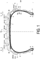
- FIG. 1
- is a meridian cross-sectional view of a pneumatic tire according to an embodiment of the present invention.
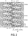
- FIG. 2
- is a front view illustrating a tread surface of a pneumatic tire according to an embodiment of the present invention.
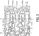
- FIG. 3
- is an unfolded view illustrating an outer block, an inner block, and a side block according to an embodiment of the present invention on a larger scale.
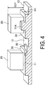
- FIG. 4
- is an explanatory diagram illustrating a platform according to an embodiment of the present invention.
- FIG. 5
- is an explanatory diagram illustrating a combination of a front view (viewed from a tire side surface) and a side view (viewed from the inner side in the tire radial direction) of the side block according to an embodiment of the present invention.
- Configurations of embodiments of the present invention will be described in detail below with reference to the accompanying drawings.
- As illustrated in
FIG. 1 , the pneumatic tire of an embodiment of the present invention includes an annular tread portion 1 extending in the tire circumferential direction, a pair ofsidewall portions 2 disposed on both sides of the tread portion 1, and a pair ofbead portions 3 disposed inward of thesidewall portions 2 in the inner side in the tire radial direction. Note that, inFIG. 1 , reference sign "CL" denotes a tire equator, and reference sign "E" denotes a ground contact edge. - In the example illustrated in
FIG. 1 , threecarcass layers right bead portions 3. The carcass layers 4A, 4B, and 4C each include a plurality of reinforcing cords extending in the tire radial direction. The carcass layers 4A and 4B are folded back around abead core 5 disposed in each of thebead portions 3 from the inner side to the outer side of the vehicle. Additionally,bead fillers 6 are disposed on the outer circumference of thebead cores 5, and eachbead filler 6 is enveloped with a main body portion and a folded back portion of each of the carcass layers 4A and 4B. Thecarcass layer 4C is disposed on the outer circumferential side of the carcass layers 4A and 4B along the carcass layers 4A and 4B. On the other hand, in the tread portion 1, a plurality of belt layers 7 (two layers inFIG. 1 ) are embedded on an outer circumferential side of the carcass layers 4A, 4B, and 4C. The belt layers 7 each include a plurality of reinforcing cords that are inclined with respect to the tire circumferential direction, with the reinforcing cords of the different layers arranged in a criss-cross manner. In thesebelt layers 7, the inclination angle of the reinforcing cords with respect to the tire circumferential direction ranges from, for example, 10° to 40°. In addition, abelt reinforcing layer 8 is provided on the outer circumferential side of the belt layers 7. Thebelt reinforcing layer 8 includes organic fiber cords oriented in the tire circumferential direction. In thebelt reinforcing layer 8, the angle of the organic fiber cords with respect to the tire circumferential direction is set, for example, to from 0° to 5°. - The present invention may be applied to such a general pneumatic tire, however, the cross-sectional structure thereof is not limited to the basic structure described above.
- As illustrated in
FIG. 2 andFIG. 3 , a plurality oflongitudinal grooves 11 extending in the tire circumferential direction, a plurality oflateral grooves 12 extending in the tire lateral direction, and a plurality ofblocks 20 defined by thelongitudinal grooves 11 and thelateral grooves 12 are formed on an outer surface of the tread portion 1 of the pneumatic tire according to an embodiment of the present invention. In particular, according to an embodiment of the present invention, a plurality of blocks 20 (hereinafter referred to as inner blocks 22) are arranged inward in the tire lateral direction of theblock 20 located most outward in the tire lateral direction among the plurality of blocks 20 (hereinafter referred to as an outer block 21), so as to be aligned along the tire lateral direction with respect to theouter block 21. A group of blocks (repeating element) is formed of theouter blocks 21 and the plurality of inner blocks 22 (that is, at least threeblocks 20 including theouter block 21, which are adjacent to each other in the tire lateral direction). The groups of blocks are repeatedly arranged across thelateral groove 12 in the tire circumferential direction. In the illustrated example, a block group (repeating element) is constituted of threeblocks 20 including theouter block 21 and the twoinner blocks 22. As described above, the repeating elements are repeatedly arranged across thelateral groove 12 in the tire circumferential direction, and the pair of repeating elements on both sides of the tire equator CL are disposed to be point-symmetrical with respect to the point on the tire equator CL. - In the example illustrated in
FIG. 2 andFIG. 3 , each block group (theouter block 21 and two inner blocks 22) is present on aplatform 30 described below, which is raised from the groove bottom of thelateral groove 12 and has a flat top surface. At this time, thelongitudinal groove 11 located between theblocks 20 constituting each block group is also present on theplatform 30. In other words, at least threeblocks 20 that include anouter block 21 and are adjacent to each other in the tire lateral direction, and at least twolongitudinal grooves 11 located between theadjacent blocks 20 are present on theplatform 30. That thelongitudinal groove 11 is present on theplatform 30 means that the groove bottom of thelongitudinal groove 11 coincides with the top surface of theplatform 30 or is located closer to the side of the road contact surface of the block than the top surface of theplatform 30. This structure is advantageous for increasing block rigidity to improve wear resistance. In addition, unevenness of the groove increases due to the presence of theplatform 30, acquiring the edge effect. Further, such increase in unevenness makes mud and the like difficult to clog inside the groove, thereby improving discharge performance for mud or the like, and traveling performance (for example, performance over mud) on unpaved roads. - Note that, as described above, the
platform 30 includes a flat top surface raised from the groove bottom of thelateral groove 12, and as illustrated inFIG. 4 , the platform is a table-shaped element on which theblock 20 and thelongitudinal groove 11 may be disposed. Note that, since theplatform 30 functions as a table on which theblock 20 and thelongitudinal groove 11 are mounted, a raised height H1 from the groove bottom is limited to be within, for example, 30% of a maximum groove depth GD1 of thelateral groove 12. Eachplatform 30 extends on both sides in the tire circumferential direction with respect to at least threeblocks 20 constituting eachplatform 30 when viewed from the road contact surface of the block. In particular, in the illustrated example, a contour line of eachplatform 30 is bent along contour lines of at least threeblocks 20 constituting eachplatform 30. - In the example illustrated in
FIG. 2 andFIG. 3 , in addition to the structure described above, a raisedbottom portion 11A raised from the groove bottom of thelongitudinal groove 11 is provided in the groove bottom of thelongitudinal groove 11 adjacent to theouter block 21. The raisedbottom portion 11A connects theouter block 21 to theinner block 22 adjacent to theouter block 21. This structure is suitable for increasing the rigidity of the connectedouter block 21 andinner block 22 to enhance wear resistance (uneven wear resistance). - According to an embodiment of the present invention, the
outer block 21 includes a narrowouter block 21a and a wideouter block 21b that differ in the position of the outer end of the road contact surface of the tread portion in the tire lateral direction. These narrowouter block 21a and wideouter block 21b are alternately arranged in the tire circumferential direction. In the illustrated example, the outer end in the tire lateral direction of the wideouter block 21b coincides with a ground contact edge E, and the outer end of the narrowouter block 21a in the tire lateral direction recedes from the ground contact edge E into the tire equator CL side. - As illustrated in
FIG. 5 , a plurality of side blocks 23 is formed in the side regions of the pneumatic tire according to an embodiment of the present invention. As illustrated in the drawings, the side blocks 23 are paired so as to face each other across aside groove 13 extending in the tire lateral direction, and the pair ofside block 23 and theside groove 13 constitute a repeating element. The repeating elements are arranged at intervals in the tire circumferential direction. The edge effects may be obtained by providing the side blocks 23 and theside grooves 13, thereby improving traveling performance (particularly, performance over rocks) on unpaved roads. - As illustrated in
FIG. 3 , theside groove 13 is positioned on an extension line of thelateral groove 12, and thelateral groove 12 and theside groove 13 substantially form a series of grooves, which is excellent in discharge performance for mud or the like. Theside block 23 includes alarge block 23a having a larger projection area and asmall block 23b having a smaller projection area. Thelarge block 23a is adjacent to the outer side of the narrowouter block 21a in the tire lateral direction, and thesmall block 23b is adjacent to the outer side of the wideouter block 21b in the tire lateral direction. - In addition, the
lateral groove 12 has awide portion 12b having a larger groove width and anarrow portion 12b having a smaller groove width at the position of theouter block 21, and thewide portions 12a and thenarrow portions 12b are alternately disposed in the tire circumferential direction. Additionally, theside groove 13 connected to thewide portion 12a converges toward the inner side in the tire radial direction, and theside groove 13 connected to thenarrow portion 12b widens toward the inner side in the tire radial direction. As a result, theside block 23 has a tapered shape (substantially triangular shape) in which the more inner side in the tire radial direction has the block width more converging toward the side of thewide portion 12a (theside groove 13 connected to thewide portion 12a). - In the example illustrated in the drawings, the road contact surface of each
side block 23 is not flat, but has an uneven shape formed of a reference surface located on theside groove 13 side, and a stepped portion that is located on the opposite side of theside groove 13 and raised from the reference surface. This structure is advantageous for improving traveling performance (particularly, performance over rocks) on unpaved roads because the uneven shape of the side blocks 23 may be complicated to achieve excellent edge effects. - In the example illustrated in the drawings, a raised
bottom portion 13A is raised from the groove bottom of theside groove 13 connected to thewide portion 12a to connect the pair of side blocks 23 to each other. In a particularly illustrated example, the raisedbottom portion 13A is formed from the outermost side of theside groove 13 in the tire radial direction to the middle portion of theside groove 13. This structure is advantageous for protecting the groove bottom of theside grooves 13 and increasing the rigidity of the connected side blocks 23, thereby improving cut resistance and traveling performance (particularly, performance over rocks) on unpaved roads. - As described above, since a complex block structure is formed in the tread portion and the side region, wear resistance on the paved roads and traveling performance on unpaved roads and cut resistance may be achieved in a compatible manner. Specifically, the narrow
outer blocks 21a and the wideouter blocks 21b are alternately arranged in the tire circumferential direction. The block structure that becomes complicated in the tire lateral direction may achieve good traction property, and improve traveling performance (particularly, performance over rocks) on unpaved roads. In addition, since the block groups (theouter blocks 21 and the inner blocks 22) are repeatedly arranged and disposed so as to be point-symmetrical with respect to a point on the tire equator CL. In achieving good traction properties due to the plurality ofblocks 20, this may improve traveling performance on unpaved roads, the rigidity balance of the overall tread surface, and suitably maintain wear resistance. On the other hand, the edge effect caused by the side blocks 23 may be ensured and improve traveling performance (particularly, performance over rocks) on unpaved roads. Furthermore, as described above, the block group (theouter block 21 and the inner block 22) and theside block 23 are disposed so as to extend in the tire lateral direction, and thus the overall rigidity balance ranging from tread surface to the side region becomes favorable, favorably maintaining wear resistance. At the same time, since thelateral groove 12 and theside groove 13 are also continuous, discharge performance for mud or the like may be increased, which is advantageous in improving traveling performance on unpaved roads. Additionally, the combination of the outer block 21 (narrowouter block 21a, wideouter block 21b) and side block 23 (large block 23a,small block 23b); and the combination of thewide portion 12a and thenarrow portion 12b of thelateral groove 12 and the groove width (converged or widened) of theside grooves 13 may optimize the uneven shape from the shoulder region to the side region, thereby improving traveling performance (particularly, the performance over rocks) and cut resistance on unpaved roads in a well-balanced manner. - A laterally implanted amount L in the outer end in the tire lateral direction on the road contact surface of the tread portion of the narrow
outer block 21a, with respect to the outer end in the tire lateral direction on the road contact surface of the tread portion of the wideouter block 21b is preferably 6 mm to 12 mm. As a result, the structure of theouter block 21 is optimized, which is advantageous in improving traction properties and improving traveling performance (particularly, performance over rocks) on unpaved roads while maintaining wear resistance (particularly uneven wear resistance). When the implanted amount L is less than 6 mm, there is substantially no change in the position of the outer end in the tire lateral direction, failing to achieve the effect of improving traction properties. If the implanted amount L is greater than 12 mm, there is a risk that wear resistance (particularly uneven wear resistance) may be affected. - The
large block 23a and thesmall block 23b may have the relative size relationships described above, but the projection area of thesmall block 23b is preferably 80% to 90% of the projection area of thelarge block 23a. Similarly, thewide portion 12a and thenarrow portion 12b may have the relative size relationship described above, but the width of thenarrow portion 12b is preferably 90% to 97% of the groove width of thewide width portion 12a. - A projection height H2 of the
side block 23 from the groove bottom of theside groove 13 is preferably from 8 mm to 13 mm. As a result, the shape of the side blocks 23 becomes favorable, which is advantageous in improving traveling performance (particularly, performance over rocks) on unpaved roads. Note that, the projection height H2 is a maximum projection height, for example, a height of a most protruding portion in the case where the road contact surface of theside block 23 is uneven as illustrated, for example. When the projection height H2 is less than 8 mm, theside block 23 is too small, making it difficult to obtain the effect of providing the side blocks 23. When the projection height H2 is greater than 13 mm, the amount of rubber (weight) of thesidewall portion 2 increases to lower traction properties, and road ability on unpaved roads (in particular, on rocky areas) may be affected. - A ratio A/SH of a length A to the tire cross-sectional height SH when measured along the tire radial direction of the side blocks 23 is preferably 0.10 to 0.30. As a result, the shape of the side blocks 23 becomes favorable, which is advantageous in improving traveling performance (particularly, performance over rocks) on unpaved roads. When the ratio A/SH is less than 0.10, the length of the
side block 23 in the tire radial direction becomes shorter, and theside block 23 itself becomes smaller. Thus, the effect of theside block 23 is limited. When the ratio A/SH is greater than 0.30, the amount of rubber (weight) of thesidewall portion 2 increases to lower traction properties, and road ability on unpaved roads (in particular, on rocky areas) may be affected. - As illustrated, when the raised
bottom portion 13A is raised from the groove bottom of theside groove 13 connected to thewide portion 12a to connect the pair of side blocks 23 to each other, a projection height H3 of the raised bottom portion from the groove bottom of theside groove 13 is preferably 3 mm to 5 mm. By allowing the raisedbottom portion 13A to connect the pair of side blocks 23 adjacent to theside groove 13 to each other in this manner, the pair of side blocks 23 and the raisedbottom portion 13A becomes a series of protrusion portions to increase the rigidity thereof, which is advantageous in improving performance over rocks while increasing cut resistance. When the projection height H3 is less than 3 mm, no substantially raised portion is formed from the groove bottom of theside groove 13, failing to connect the side blocks 23 to each other, thereby sufficiently increasing the rigidity. If the projection height H3 is greater than 5 mm, the groove volume of theside groove 13 decreases, which may affect discharge performance for mud or the like. - A raised height H1 of the
platform 30 is preferably not greater than 30% of a maximum groove depth GD1 of thelateral groove 12, as previously described, and more preferably 5% to 25% of the maximum groove depth GD1 of thelateral groove 12. Setting the height H1 of theplatform 30 to the appropriate range as described above ensures a sufficient groove area of thelateral grooves 12 to achieve good performance over mud and further, the block rigidity of theplatform 30 may be ensured to improve wear resistance. As a result, these performances may be achieved in a well-balanced manner. At this time, when the raised height H1 of theplatform 30 is less than 5% of the maximum groove depth GD1 of thelateral groove 12, the effect of increasing block rigidity is limited, making it difficult to sufficiently ensure wear resistance. When the raised height H1 of theplatform 30 is greater than 25% of the maximum groove depth GD1 of thelateral groove 12, the groove area of thelateral grooves 12 may decrease, which may affect the performance over mud. - Since the
platform 30 extends on both sides in the tire circumferential direction with respect to at least threeblocks 20 constituting eachplatform 30 as described above, theplatform 30 is wider than the road contact surface of at least threeblocks 20 constituting eachplatform 30. In particular, the ratio of the total area of the road contact surfaces of theblocks 20 present on theplatform 30 to the projected area of theplatform 30 is preferably 55% to 75%. As a result, the balance between theplatform 30 and theblock 20 becomes favorable, which is advantageous in achieving both of performance over mud and wear resistance in a well-balanced manner. When the ratio of the area is smaller than 55%, the effect of increasing the block rigidity is limited, making it difficult to sufficiently ensure wear resistance. When the ratio of the area is greater than 75%, the groove area of thelateral groove 12 decreases, which may affect performance over mud. Note that, the projected area of theplatform 30 refers to the area inside the contour line of the platform 15 when viewed from the road contact surface side of the block (the total area including the portion where theblock 13 is present). - 21 types of pneumatic tires in Comparative Examples 1 to 4 and Examples 1 to 16 with a tire size of 35 x 12.50R17, having the basic structure illustrated in
FIG. 1 , based on the tread pattern illustrated inFIG. 2 were produced in following conditions set as illustrated in Tables 1 and 2: presence or absence of wide outer block, presence or absence of narrow outer block, implanted amount L, large block arrangement, small block arrangement, presence or absence of narrow portion of lateral groove, presence or absence of wide portion of lateral groove, change in groove width of side groove connected to narrow portion, change in width of side groove connected to wide portion, presence or absence of platform, projection height H2 of side block, ratio A/SH of length A to tire cross-sectional height SH measured along tire radial direction of side block, and projection height H3 of raised bottom portion of the side grooves. - In Table 1, the "Large Block Arrangement" and "Small Block Arrangement" indicates whether the large block or small block is disposed so as to be adjacent to either the narrow outer block or the wide outer block, "Narrow" indicates the case where the large block or small block is disposed adjacent to the narrow outer block, and "Wide" indicates the case where the large block or small block is disposed adjacent to the wide outer block. In Table 1, "Change in Width of Side Groove Connected to Narrow Portion" and "Change in Width of Side Groove Connected to Wide Portion" indicates whether the width of the side groove converges toward the inner side in the tire radial direction, or widens toward the inner side in the tire radial direction, "Converged" indicates the case where the width converges toward the inner side in the tire radial direction, and "Widened" indicates the case where the width widens toward the inner side in the tire radial direction.
- In Comparative Example 1, "Presence or Absence of Wide Outer Block" is "Present", and the "presence or absence of narrow outer block" is "No", which means that the outer ends in the width direction of all outer blocks match the ground contact edge, and only wide outer blocks are present (no narrow outer block is present). Additionally, in Comparative Example 1, both of "Presence or Absence of Narrow Portion" and "Presence or Absence of Wide Portion" are "Absent", which means that the lateral groove has a constant width and there is no change in the groove width (neither narrow nor wide portion is present).
- For wear resistance, performance over mud, performance over rocks, and cut resistance, these pneumatic tires were evaluated by a following evaluation method, and the results are also illustrated in Tables 1 and 2.
- The test tires each were assembled to respective wheels with a rim size of 17 x 10.0 J, inflated to an air pressure of 240 kPa, and mounted on a test vehicle (four wheel drive). After driving on a paved road for 30,000 km, the wear amount of was measured. Evaluation results were expressed as index values with the reciprocal of measurements in Conventional Example 1 being assigned the index value of 100. Larger index values indicate smaller wear amount and superior wear resistance.
- The test tires each were assembled to respective wheels having a rim size of 17 x 10.0 J, inflated to an air pressure of 240 kPa, and mounted on a test vehicle (four wheel drive). For accelerating performance and escaping performance, sensory evaluation by a test driver was performed on a muddy road surface. Evaluation results are expressed as index values with Conventional Example 1 being assigned the index value of 100. Larger index values indicate superior performance over mud.
- The test tires each were assembled to respective wheels having a rim size of 17 x 10.0 J, inflated to an air pressure of 240 kPa, and mounted on a test vehicle (four wheel drive). For traction properties and starting performance, sensory evaluation by a test driver was performed on a rocky road surface. Evaluation results are expressed as index values with Conventional Example 1 being assigned the index value of 100. Larger index value indicates superior performance over rocks.
- After evaluation of performance over rocks described above, the cut edge length of a damage generated in the side region and the shoulder region was measured. Evaluation results were expressed as index values with the reciprocal of values in Conventional Example 1 being assigned the index value of 100. Larger index values indicate shorter cut edge length and superior cut resistance.
[Table 1] Comparative Example 1 Comparative Example 2 Comparative Example 3 Example 1 Comparative Example 4 Example 2 Example 3 Comparative Example 5 Example 4 Presence/Absence of Wide Outer Block Present Present Present Present Present Present Present Present Present Presence/Absence of Narrow Outer Block Absent Present Present Present Present Present Present Present Present Implanted Amount L mm - 7 7 7 4 6 12 14 7 Large Block Arrangement Wide Wide Narrow Narrow Narrow Narrow Narrow Narrow Narrow Small Block A rrangemen t Wide Narrow Wide Wide Wide Wide Wide Wide Wide Presence/Absence of Narrow Portion Absent Present Present Present Present Present Present Present Present Presence/Absence of Wide Portion Absent Present Present Present Present Present Present Present Present Change in Groove Width of Side Groove Connected to Narrow Portion - Widened Converged Widened Widened Widened Widened Widened Widened Change in Width of Side Groove Connected to Wide Portion - Converged Widened Converged Converged Converged Converged Converged Converged Presence/Absence of Platform Absent Present Present Present Present Present Present Present Absent Projection Height H2 mm 12 12 12 12 12 12 12 12 12 Ratio A/SH 0.2 0.2 0.2 0.2 0.2 0.2 0.2 0.2 0.2 Projection Height H3 mm 4 4 4 4 4 4 4 4 4 Wear Resistance Index Value 100 97 98 102 102 102 101 99 101 Performance over mud Index Value 100 98 101 105 100 102 105 105 103 Performance over rocks Index Value 100 98 101 105 100 102 105 105 105 Cut Resistance Index Value 100 99 97 102 102 102 101 100 102 [Table 2] Example 5 Example 6 Example 7 Example 8 Example 9 Example 10 Example 11 Example 12 Example 13 Example 14 Example 15 Example 16 Presence/Absence of Wide Outer block Present Present Present Present Present Present Present Present Present Present Present Present Presence/Absence of Narrow Outer Block Present Present Present Present Present Present Present Present Present Present Present Present Implanted Amount L mm 7 7 7 7 7 7 7 7 7 7 7 7 Arrangement of Large Block Narrow Narrow Narrow Narrow Narrow Narrow Narrow Narrow Narrow Narrow Narrow Narrow Arrangement of Small Block Wide Wide Wide Wide Wide Wide Wide Wide Wide Wide Wide Wide Presence/Absence of Narrow Portion Present Present Present Present Present Present Present Present Present Present Present Present Presence/Absence of Wide Portion Present Present Present Present Present Present Present Present Present Present Present Present Change in Groove Width of Side Groove Connected to Narrow Portion Widened Widened Widened Widened Widened Widened Widened Widened Widened Widened Widened Widened Change in Width of Side Groove Connected to Wide Portion Converged Converged Converged Converged Converged Converged Converged Converged Converged Converged Converged Converged Presence/Absence of Platform Present Present Present Present Present Present Present Present Present Present Present Present Projection Height H2 mm 5 8 13 15 12 12 12 12 12 12 12 12 Ratio A/SH 0.2 0.2 0.2 0.2 0.09 0.10 0.30 0.35 0.2 0.2 0.2 0.2 Projection Height H3 mm 4 4 4 4 4 4 4 4 2 3 5 6 Wear Resistance Index Value 102 102 101 100 102 102 101 100 102 102 103 103 Performance over mud Index Value 102 104 105 105 102 104 105 105 105 105 103 102 Performance over rocks Index Value 102 104 105 105 102 104 105 105 105 105 103 102 Cut Resistance Index Value 101 102 102 102 101 102 102 102 101 102 103 104 - As is clear from Tables 1 and 2, as compared to Comparative Example 1, Examples 1 to 16 provided improved wear resistance, performance over mud, performance over rocks, and cut resistance and achieved these performances in a well-balanced manner to a high degree. Although only the performance over mud on the muddy road surface and performance over rocks on the rocky road surface were evaluated, even when driving on other unpaved roads (snowy road, sandy ground, and the like), the tires of an embodiment of the present invention exhibited the same function as on mud on the muddy road surface and rocks on the rocky road surface against snow, sand, stones, and the like on the road surface, and thus exhibited excellent traveling performance on unpaved roads.
- On the contrary, in Comparative Example 2, the wide outer block and the large block were adjacent to each other, the narrow outer block and the small block were adjacent to each other, and the arrangement of these blocks was reversed. As a result, performance over mud and performance over rocks cannot be improved, and wear resistance and cut resistance were also negatively affected. In Comparative Example 3, the groove width of the side groove connected to the narrow portion of the lateral groove converged toward the inner side in the tire radial direction, the groove width of the side groove connected to the wide portion of the lateral groove widened toward the inner side in the tire radial direction, and the change in groove width of the side groove was reversed. As a result, wear resistance and cut resistance were negatively affected. In Comparative Example 4, the implanted amount L was too small and thus, the effect of improving performance over mud and performance over rocks was not acquired. In Comparative Example 5, the implanted amount L was too large and thus, wear resistance was negatively affected.
-
- 1 Tread portion
- 2 Sidewall portion
- 3 Bead portion
- 4A, 4B, 4C Carcass layer
- 5 Bead core
- 6 Bead filler
- 7 Belt layer
- 8 Belt reinforcing layer
- 11 Longitudinal groove
- 11A Raised bottom portion
- 12 Lateral groove
- 12a Wide portion
- 12b Narrow portion
- 13 Side groove
- 13A Raised bottom portion
- 20 Block
- 21 Outer block
- 21a Narrow outer block
- 21b Wide outer block
- 22 Inner block
- 23 Side block
- 23a Large block
- 23b Small block
- 30 Platform
- CL Tire equator
- E Ground contact edge
Claims (6)
- A pneumatic tire comprising:a tread portion extending in a tire circumferential direction to have an annular shape;a pair of sidewall portions disposed on both sides of the tread portion; anda pair of bead portions disposed inward of the sidewall portions in the tire radial direction, whereinthe tread portion is provided with a plurality of longitudinal grooves extending in a tire circumferential direction, a plurality of lateral grooves extending in a tire width direction, and a plurality of blocks defined by the longitudinal grooves and the lateral grooves,
the plurality of blocks include an outer block located on an outermost side in the tire lateral direction,
the outer block includes a narrow outer block and a wide outer block having different positions at an outer end in the tire lateral direction on a road contact surface of the tread portion, the narrow outer block and the wide outer block are alternately arranged in the tire circumferential direction, at least three blocks adjacent to each other in the tire lateral direction including the outer blocks and at least two longitudinal grooves located between the blocks constitute a repeating element, the repeating element is repeatedly arranged across the lateral groove in the tire circumferential direction, and the pair of repeating elements on both sides of a tire equator are disposed so as to be point-symmetrically with respect to a point on the tire equator,
a side region located outward in the tire lateral direction of a shoulder region of the tread portion is provided with a plurality of side grooves extending in the tire lateral direction, the side grooves being positioned on extension lines of the lateral grooves, and a plurality of side blocks defined by the side grooves,
the side blocks each include a large block having a larger projection area and a small block with a smaller projection area, the large block is adjacent to the outer side of the narrow outer block in the tire lateral direction, the small block is adjacent to the outer side of the wide outer block in the tire lateral direction,
some of the lateral grooves each have a wide portion having a larger groove width at positions of the outer blocks, the other of the lateral grooves each have a narrow portion having a smaller groove width at positions of the outer blocks,
the lateral groove having the wide portion and the lateral groove having the narrow portion are alternately disposed in the tire circumferential direction,
a groove width of the side groove connected to the wide portion converges toward the inner side in the tire radial direction,
a groove width of the side groove connected to the narrow portion widens toward the inner side in the tire radial direction, and
the side blocks each are tapered such that a more inner portion in the tire radial direction has a block width more converging toward the wide portion side. - The pneumatic tire according to claim 1, wherein
an implanted amount of the outer end in the tire lateral direction on the road contact surface of the tread portion of the narrow outer block, with respect to the outer end in the tire lateral direction on the road contact surface of the tread portion of the wide outer block is preferably 6 mm to 12 mm. - The pneumatic tire according to claim 1 or 2, wherein
the repeating elements each are present on a platform raised from a groove bottom of the lateral groove, the platform having a flat top surface and extending on both sides in the tire circumferential direction with respect to the at least three blocks. - The pneumatic tire according to any one of claims 1 to 3, wherein
a projection height of the side block from the groove bottom of the side groove is from 8 mm to 13 mm. - The pneumatic tire according to any one of claims 1 to 4, wherein
a ratio A/SH of a length A to a tire cross-sectional height SH when measured along the tire radial direction of the side block is 0.10 to 0.30. - The pneumatic tire according to any one of claims 1 to 5, further comprising
a raised bottom portion raised from the groove bottom of the side groove connected to the wide portion to connect the pair of side blocks adjacent to the side groove to each other, wherein a projection height of the raised bottom portion from the groove bottom of the side groove is 3 mm to 5 mm.
Applications Claiming Priority (2)
| Application Number | Priority Date | Filing Date | Title |
|---|---|---|---|
| JP2017149976A JP6521000B2 (en) | 2017-08-02 | 2017-08-02 | Pneumatic tire |
| PCT/JP2018/028090 WO2019026759A1 (en) | 2017-08-02 | 2018-07-26 | Pneumatic tire |
Publications (3)
| Publication Number | Publication Date |
|---|---|
| EP3663104A1 true EP3663104A1 (en) | 2020-06-10 |
| EP3663104A4 EP3663104A4 (en) | 2021-05-12 |
| EP3663104B1 EP3663104B1 (en) | 2022-07-20 |
Family
ID=65233139
Family Applications (1)
| Application Number | Title | Priority Date | Filing Date |
|---|---|---|---|
| EP18840874.4A Active EP3663104B1 (en) | 2017-08-02 | 2018-07-26 | Pneumatic tire |
Country Status (5)
| Country | Link |
|---|---|
| US (1) | US11613145B2 (en) |
| EP (1) | EP3663104B1 (en) |
| JP (1) | JP6521000B2 (en) |
| CN (1) | CN110958949B (en) |
| WO (1) | WO2019026759A1 (en) |
Families Citing this family (3)
| Publication number | Priority date | Publication date | Assignee | Title |
|---|---|---|---|---|
| JP6604390B2 (en) * | 2018-01-16 | 2019-11-13 | 横浜ゴム株式会社 | Pneumatic tire |
| CN114919339B (en) * | 2022-01-28 | 2023-11-03 | 厦门正新橡胶工业有限公司 | Pneumatic tire of all-terrain vehicle for rock climbing and tread pattern structure of pneumatic tire |
| CN116039296B (en) * | 2022-12-26 | 2024-05-07 | 湖北奥莱斯轮胎股份有限公司 | Anti-wet slider radial tire tread structure |
Family Cites Families (30)
| Publication number | Priority date | Publication date | Assignee | Title |
|---|---|---|---|---|
| DE2549668A1 (en) | 1975-11-05 | 1977-05-12 | Uniroyal Ag | VEHICLE TIRES WITH RADIAL CARCASS |
| JP2744446B2 (en) * | 1988-11-09 | 1998-04-28 | 株式会社ブリヂストン | Vehicle snow tires |
| US5361814A (en) | 1989-11-15 | 1994-11-08 | The Goodyear Tire & Rubber Company | Asymmetric tire |
| JPH03176210A (en) * | 1989-12-04 | 1991-07-31 | Ohtsu Tire & Rubber Co Ltd :The | Tire for snowy and icy road |
| US5085259A (en) | 1990-07-16 | 1992-02-04 | The Goodyear Tire & Rubber Company | Tire tread |
| JP3391692B2 (en) * | 1998-04-03 | 2003-03-31 | 住友ゴム工業株式会社 | Pneumatic tire |
| JPH11310011A (en) * | 1998-04-30 | 1999-11-09 | Bridgestone Corp | Pneumatic radial tire |
| AU3065499A (en) * | 1998-08-26 | 1999-11-01 | Goodyear Tire And Rubber Company, The | An on/off-road tread |
| JP4367869B2 (en) * | 1999-04-28 | 2009-11-18 | 横浜ゴム株式会社 | Pneumatic radial tire |
| JP4518641B2 (en) * | 2000-07-18 | 2010-08-04 | 株式会社ブリヂストン | Pneumatic tire |
| US6920906B2 (en) * | 2001-08-31 | 2005-07-26 | Bridgestone/Firestone North American Tire, Llc | Pneumatic tire with sidewall projections |
| JP4048058B2 (en) * | 2002-01-25 | 2008-02-13 | 株式会社ブリヂストン | Pneumatic tire |
| US7784511B2 (en) * | 2007-03-02 | 2010-08-31 | The Goodyear Tire & Rubber Company | Pneumatic tire having extension blocks |
| JP4338743B2 (en) * | 2007-03-15 | 2009-10-07 | 住友ゴム工業株式会社 | Pneumatic tire |
| US8056592B2 (en) * | 2007-10-31 | 2011-11-15 | The Goodyear Tire + Rubber Company, Inc. | Grip tire with added puncture protection |
| WO2009069585A1 (en) * | 2007-11-28 | 2009-06-04 | Sumitomo Rubber Industries, Ltd. | Pneumatic tire |
| JP4980872B2 (en) * | 2007-12-20 | 2012-07-18 | 東洋ゴム工業株式会社 | Pneumatic tire |
| US8079391B2 (en) * | 2008-08-19 | 2011-12-20 | The Goodyear Tire & Rubber Company | Pneumatic tire with sidewall tread projections |
| US9027611B2 (en) * | 2008-09-11 | 2015-05-12 | The Goodyear Tire & Rubber Company | Multi-purpose tire |
| JP5632823B2 (en) * | 2011-12-26 | 2014-11-26 | 住友ゴム工業株式会社 | Heavy duty pneumatic tire |
| JP5403077B2 (en) * | 2012-01-13 | 2014-01-29 | 横浜ゴム株式会社 | Pneumatic tire |
| JP2015077931A (en) * | 2013-10-18 | 2015-04-23 | 横浜ゴム株式会社 | Pneumatic tire |
| JP5750541B1 (en) * | 2014-11-11 | 2015-07-22 | 東洋ゴム工業株式会社 | Pneumatic tire |
| EP3305553B1 (en) | 2015-06-03 | 2019-11-13 | Bridgestone Corporation | Pneumatic tire |
| JP6607708B2 (en) * | 2015-06-03 | 2019-11-20 | 株式会社ブリヂストン | Pneumatic tire |
| CN105172479A (en) * | 2015-09-18 | 2015-12-23 | 安徽佳通乘用子午线轮胎有限公司 | Tire having cross-country comprehensive performance |
| JP6612585B2 (en) * | 2015-10-30 | 2019-11-27 | Toyo Tire株式会社 | Pneumatic tire |
| JP2017114384A (en) | 2015-12-25 | 2017-06-29 | 東洋ゴム工業株式会社 | Pneumatic tire |
| JP6142930B1 (en) * | 2016-01-14 | 2017-06-07 | 横浜ゴム株式会社 | Pneumatic tire |
| CN206086221U (en) * | 2016-08-31 | 2017-04-12 | 赛轮金宇集团股份有限公司 | Ice and snow road surface car tyre |
-
2017
- 2017-08-02 JP JP2017149976A patent/JP6521000B2/en active Active
-
2018
- 2018-07-26 EP EP18840874.4A patent/EP3663104B1/en active Active
- 2018-07-26 US US16/636,009 patent/US11613145B2/en active Active
- 2018-07-26 WO PCT/JP2018/028090 patent/WO2019026759A1/en unknown
- 2018-07-26 CN CN201880048580.8A patent/CN110958949B/en active Active
Also Published As
| Publication number | Publication date |
|---|---|
| CN110958949A (en) | 2020-04-03 |
| EP3663104A4 (en) | 2021-05-12 |
| US11613145B2 (en) | 2023-03-28 |
| JP6521000B2 (en) | 2019-05-29 |
| JP2019026175A (en) | 2019-02-21 |
| CN110958949B (en) | 2021-09-10 |
| US20210138843A1 (en) | 2021-05-13 |
| EP3663104B1 (en) | 2022-07-20 |
| WO2019026759A1 (en) | 2019-02-07 |
Similar Documents
| Publication | Publication Date | Title |
|---|---|---|
| EP3659823B1 (en) | Pneumatic tire | |
| US11654719B2 (en) | Pneumatic tire | |
| US20220118796A1 (en) | Pneumatic tire | |
| EP3659824B1 (en) | Pneumatic tire | |
| EP3663104B1 (en) | Pneumatic tire | |
| CN110191813B (en) | Pneumatic tire | |
| US11951776B2 (en) | Pneumatic tire | |
| EP3663106B1 (en) | Pneumatic tire | |
| US11718130B2 (en) | Pneumatic tire | |
| AU2019339359B2 (en) | Pneumatic tire | |
| WO2018164072A1 (en) | Pneumatic tire | |
| CN113573918B (en) | Pneumatic tire | |
| US20220063349A1 (en) | Pneumatic tire |
Legal Events
| Date | Code | Title | Description |
|---|---|---|---|
| STAA | Information on the status of an ep patent application or granted ep patent |
Free format text: STATUS: THE INTERNATIONAL PUBLICATION HAS BEEN MADE |
|
| PUAI | Public reference made under article 153(3) epc to a published international application that has entered the european phase |
Free format text: ORIGINAL CODE: 0009012 |
|
| STAA | Information on the status of an ep patent application or granted ep patent |
Free format text: STATUS: REQUEST FOR EXAMINATION WAS MADE |
|
| 17P | Request for examination filed |
Effective date: 20200203 |
|
| AK | Designated contracting states |
Kind code of ref document: A1 Designated state(s): AL AT BE BG CH CY CZ DE DK EE ES FI FR GB GR HR HU IE IS IT LI LT LU LV MC MK MT NL NO PL PT RO RS SE SI SK SM TR |
|
| AX | Request for extension of the european patent |
Extension state: BA ME |
|
| DAV | Request for validation of the european patent (deleted) | ||
| DAX | Request for extension of the european patent (deleted) | ||
| A4 | Supplementary search report drawn up and despatched |
Effective date: 20210413 |
|
| RIC1 | Information provided on ipc code assigned before grant |
Ipc: B60C 11/03 20060101AFI20210407BHEP Ipc: B60C 11/13 20060101ALI20210407BHEP Ipc: B60C 11/01 20060101ALI20210407BHEP Ipc: B60C 13/00 20060101ALI20210407BHEP |
|
| RIC1 | Information provided on ipc code assigned before grant |
Ipc: B60C 13/00 20060101ALI20211209BHEP Ipc: B60C 11/01 20060101ALI20211209BHEP Ipc: B60C 11/13 20060101ALI20211209BHEP Ipc: B60C 11/03 20060101AFI20211209BHEP |
|
| GRAP | Despatch of communication of intention to grant a patent |
Free format text: ORIGINAL CODE: EPIDOSNIGR1 |
|
| STAA | Information on the status of an ep patent application or granted ep patent |
Free format text: STATUS: GRANT OF PATENT IS INTENDED |
|
| INTG | Intention to grant announced |
Effective date: 20220126 |
|
| GRAS | Grant fee paid |
Free format text: ORIGINAL CODE: EPIDOSNIGR3 |
|
| GRAA | (expected) grant |
Free format text: ORIGINAL CODE: 0009210 |
|
| STAA | Information on the status of an ep patent application or granted ep patent |
Free format text: STATUS: THE PATENT HAS BEEN GRANTED |
|
| AK | Designated contracting states |
Kind code of ref document: B1 Designated state(s): AL AT BE BG CH CY CZ DE DK EE ES FI FR GB GR HR HU IE IS IT LI LT LU LV MC MK MT NL NO PL PT RO RS SE SI SK SM TR |
|
| REG | Reference to a national code |
Ref country code: CH Ref legal event code: EP |
|
| REG | Reference to a national code |
Ref country code: DE Ref legal event code: R096 Ref document number: 602018038263 Country of ref document: DE |
|
| REG | Reference to a national code |
Ref country code: AT Ref legal event code: REF Ref document number: 1505307 Country of ref document: AT Kind code of ref document: T Effective date: 20220815 |
|
| REG | Reference to a national code |
Ref country code: IE Ref legal event code: FG4D |
|
| REG | Reference to a national code |
Ref country code: LT Ref legal event code: MG9D |
|
| REG | Reference to a national code |
Ref country code: NL Ref legal event code: MP Effective date: 20220720 |
|
| PG25 | Lapsed in a contracting state [announced via postgrant information from national office to epo] |
Ref country code: SE Free format text: LAPSE BECAUSE OF FAILURE TO SUBMIT A TRANSLATION OF THE DESCRIPTION OR TO PAY THE FEE WITHIN THE PRESCRIBED TIME-LIMIT Effective date: 20220720 Ref country code: RS Free format text: LAPSE BECAUSE OF FAILURE TO SUBMIT A TRANSLATION OF THE DESCRIPTION OR TO PAY THE FEE WITHIN THE PRESCRIBED TIME-LIMIT Effective date: 20220720 Ref country code: PT Free format text: LAPSE BECAUSE OF FAILURE TO SUBMIT A TRANSLATION OF THE DESCRIPTION OR TO PAY THE FEE WITHIN THE PRESCRIBED TIME-LIMIT Effective date: 20221121 Ref country code: NO Free format text: LAPSE BECAUSE OF FAILURE TO SUBMIT A TRANSLATION OF THE DESCRIPTION OR TO PAY THE FEE WITHIN THE PRESCRIBED TIME-LIMIT Effective date: 20221020 Ref country code: NL Free format text: LAPSE BECAUSE OF FAILURE TO SUBMIT A TRANSLATION OF THE DESCRIPTION OR TO PAY THE FEE WITHIN THE PRESCRIBED TIME-LIMIT Effective date: 20220720 Ref country code: LV Free format text: LAPSE BECAUSE OF FAILURE TO SUBMIT A TRANSLATION OF THE DESCRIPTION OR TO PAY THE FEE WITHIN THE PRESCRIBED TIME-LIMIT Effective date: 20220720 Ref country code: LT Free format text: LAPSE BECAUSE OF FAILURE TO SUBMIT A TRANSLATION OF THE DESCRIPTION OR TO PAY THE FEE WITHIN THE PRESCRIBED TIME-LIMIT Effective date: 20220720 Ref country code: FI Free format text: LAPSE BECAUSE OF FAILURE TO SUBMIT A TRANSLATION OF THE DESCRIPTION OR TO PAY THE FEE WITHIN THE PRESCRIBED TIME-LIMIT Effective date: 20220720 Ref country code: ES Free format text: LAPSE BECAUSE OF FAILURE TO SUBMIT A TRANSLATION OF THE DESCRIPTION OR TO PAY THE FEE WITHIN THE PRESCRIBED TIME-LIMIT Effective date: 20220720 |
|
| REG | Reference to a national code |
Ref country code: AT Ref legal event code: MK05 Ref document number: 1505307 Country of ref document: AT Kind code of ref document: T Effective date: 20220720 |
|
| PG25 | Lapsed in a contracting state [announced via postgrant information from national office to epo] |
Ref country code: PL Free format text: LAPSE BECAUSE OF FAILURE TO SUBMIT A TRANSLATION OF THE DESCRIPTION OR TO PAY THE FEE WITHIN THE PRESCRIBED TIME-LIMIT Effective date: 20220720 Ref country code: IS Free format text: LAPSE BECAUSE OF FAILURE TO SUBMIT A TRANSLATION OF THE DESCRIPTION OR TO PAY THE FEE WITHIN THE PRESCRIBED TIME-LIMIT Effective date: 20221120 Ref country code: HR Free format text: LAPSE BECAUSE OF FAILURE TO SUBMIT A TRANSLATION OF THE DESCRIPTION OR TO PAY THE FEE WITHIN THE PRESCRIBED TIME-LIMIT Effective date: 20220720 Ref country code: GR Free format text: LAPSE BECAUSE OF FAILURE TO SUBMIT A TRANSLATION OF THE DESCRIPTION OR TO PAY THE FEE WITHIN THE PRESCRIBED TIME-LIMIT Effective date: 20221021 |
|
| REG | Reference to a national code |
Ref country code: CH Ref legal event code: PL |
|
| REG | Reference to a national code |
Ref country code: BE Ref legal event code: MM Effective date: 20220731 |
|
| REG | Reference to a national code |
Ref country code: DE Ref legal event code: R097 Ref document number: 602018038263 Country of ref document: DE |
|
| PG25 | Lapsed in a contracting state [announced via postgrant information from national office to epo] |
Ref country code: SM Free format text: LAPSE BECAUSE OF FAILURE TO SUBMIT A TRANSLATION OF THE DESCRIPTION OR TO PAY THE FEE WITHIN THE PRESCRIBED TIME-LIMIT Effective date: 20220720 Ref country code: RO Free format text: LAPSE BECAUSE OF FAILURE TO SUBMIT A TRANSLATION OF THE DESCRIPTION OR TO PAY THE FEE WITHIN THE PRESCRIBED TIME-LIMIT Effective date: 20220720 Ref country code: MC Free format text: LAPSE BECAUSE OF FAILURE TO SUBMIT A TRANSLATION OF THE DESCRIPTION OR TO PAY THE FEE WITHIN THE PRESCRIBED TIME-LIMIT Effective date: 20220720 Ref country code: LU Free format text: LAPSE BECAUSE OF NON-PAYMENT OF DUE FEES Effective date: 20220726 Ref country code: LI Free format text: LAPSE BECAUSE OF NON-PAYMENT OF DUE FEES Effective date: 20220731 Ref country code: DK Free format text: LAPSE BECAUSE OF FAILURE TO SUBMIT A TRANSLATION OF THE DESCRIPTION OR TO PAY THE FEE WITHIN THE PRESCRIBED TIME-LIMIT Effective date: 20220720 Ref country code: CZ Free format text: LAPSE BECAUSE OF FAILURE TO SUBMIT A TRANSLATION OF THE DESCRIPTION OR TO PAY THE FEE WITHIN THE PRESCRIBED TIME-LIMIT Effective date: 20220720 Ref country code: CH Free format text: LAPSE BECAUSE OF NON-PAYMENT OF DUE FEES Effective date: 20220731 Ref country code: AT Free format text: LAPSE BECAUSE OF FAILURE TO SUBMIT A TRANSLATION OF THE DESCRIPTION OR TO PAY THE FEE WITHIN THE PRESCRIBED TIME-LIMIT Effective date: 20220720 |
|
| PLBE | No opposition filed within time limit |
Free format text: ORIGINAL CODE: 0009261 |
|
| STAA | Information on the status of an ep patent application or granted ep patent |
Free format text: STATUS: NO OPPOSITION FILED WITHIN TIME LIMIT |
|
| PG25 | Lapsed in a contracting state [announced via postgrant information from national office to epo] |
Ref country code: SK Free format text: LAPSE BECAUSE OF FAILURE TO SUBMIT A TRANSLATION OF THE DESCRIPTION OR TO PAY THE FEE WITHIN THE PRESCRIBED TIME-LIMIT Effective date: 20220720 Ref country code: EE Free format text: LAPSE BECAUSE OF FAILURE TO SUBMIT A TRANSLATION OF THE DESCRIPTION OR TO PAY THE FEE WITHIN THE PRESCRIBED TIME-LIMIT Effective date: 20220720 Ref country code: BE Free format text: LAPSE BECAUSE OF NON-PAYMENT OF DUE FEES Effective date: 20220731 |
|
| P01 | Opt-out of the competence of the unified patent court (upc) registered |
Effective date: 20230512 |
|
| 26N | No opposition filed |
Effective date: 20230421 |
|
| GBPC | Gb: european patent ceased through non-payment of renewal fee |
Effective date: 20221020 |
|
| PG25 | Lapsed in a contracting state [announced via postgrant information from national office to epo] |
Ref country code: AL Free format text: LAPSE BECAUSE OF FAILURE TO SUBMIT A TRANSLATION OF THE DESCRIPTION OR TO PAY THE FEE WITHIN THE PRESCRIBED TIME-LIMIT Effective date: 20220720 |
|
| PG25 | Lapsed in a contracting state [announced via postgrant information from national office to epo] |
Ref country code: IE Free format text: LAPSE BECAUSE OF NON-PAYMENT OF DUE FEES Effective date: 20220726 Ref country code: FR Free format text: LAPSE BECAUSE OF NON-PAYMENT OF DUE FEES Effective date: 20220920 |
|
| PG25 | Lapsed in a contracting state [announced via postgrant information from national office to epo] |
Ref country code: SI Free format text: LAPSE BECAUSE OF FAILURE TO SUBMIT A TRANSLATION OF THE DESCRIPTION OR TO PAY THE FEE WITHIN THE PRESCRIBED TIME-LIMIT Effective date: 20220720 |
|
| PG25 | Lapsed in a contracting state [announced via postgrant information from national office to epo] |
Ref country code: GB Free format text: LAPSE BECAUSE OF NON-PAYMENT OF DUE FEES Effective date: 20221020 |
|
| PGFP | Annual fee paid to national office [announced via postgrant information from national office to epo] |
Ref country code: DE Payment date: 20230531 Year of fee payment: 6 |
|
| PG25 | Lapsed in a contracting state [announced via postgrant information from national office to epo] |
Ref country code: MK Free format text: LAPSE BECAUSE OF FAILURE TO SUBMIT A TRANSLATION OF THE DESCRIPTION OR TO PAY THE FEE WITHIN THE PRESCRIBED TIME-LIMIT Effective date: 20220720 Ref country code: CY Free format text: LAPSE BECAUSE OF FAILURE TO SUBMIT A TRANSLATION OF THE DESCRIPTION OR TO PAY THE FEE WITHIN THE PRESCRIBED TIME-LIMIT Effective date: 20220720 |