EP3662853B1 - Coupling device, in particular for use in orthopedic surgery - Google Patents
Coupling device, in particular for use in orthopedic surgery Download PDFInfo
- Publication number
- EP3662853B1 EP3662853B1 EP18210576.7A EP18210576A EP3662853B1 EP 3662853 B1 EP3662853 B1 EP 3662853B1 EP 18210576 A EP18210576 A EP 18210576A EP 3662853 B1 EP3662853 B1 EP 3662853B1
- Authority
- EP
- European Patent Office
- Prior art keywords
- connection
- coupling device
- coupling
- bone anchor
- connection member
- Prior art date
- Legal status (The legal status is an assumption and is not a legal conclusion. Google has not performed a legal analysis and makes no representation as to the accuracy of the status listed.)
- Active
Links
Images

Classifications
-
- A—HUMAN NECESSITIES
- A61—MEDICAL OR VETERINARY SCIENCE; HYGIENE
- A61B—DIAGNOSIS; SURGERY; IDENTIFICATION
- A61B17/00—Surgical instruments, devices or methods, e.g. tourniquets
- A61B17/56—Surgical instruments or methods for treatment of bones or joints; Devices specially adapted therefor
- A61B17/58—Surgical instruments or methods for treatment of bones or joints; Devices specially adapted therefor for osteosynthesis, e.g. bone plates, screws, setting implements or the like
- A61B17/68—Internal fixation devices, including fasteners and spinal fixators, even if a part thereof projects from the skin
- A61B17/70—Spinal positioners or stabilisers ; Bone stabilisers comprising fluid filler in an implant
- A61B17/7001—Screws or hooks combined with longitudinal elements which do not contact vertebrae
- A61B17/7002—Longitudinal elements, e.g. rods
-
- A—HUMAN NECESSITIES
- A61—MEDICAL OR VETERINARY SCIENCE; HYGIENE
- A61B—DIAGNOSIS; SURGERY; IDENTIFICATION
- A61B17/00—Surgical instruments, devices or methods, e.g. tourniquets
- A61B17/56—Surgical instruments or methods for treatment of bones or joints; Devices specially adapted therefor
- A61B17/58—Surgical instruments or methods for treatment of bones or joints; Devices specially adapted therefor for osteosynthesis, e.g. bone plates, screws, setting implements or the like
- A61B17/60—Surgical instruments or methods for treatment of bones or joints; Devices specially adapted therefor for osteosynthesis, e.g. bone plates, screws, setting implements or the like for external osteosynthesis, e.g. distractors, contractors
- A61B17/64—Devices extending alongside the bones to be positioned
- A61B17/645—Devices extending alongside the bones to be positioned comprising a framework
-
- A—HUMAN NECESSITIES
- A61—MEDICAL OR VETERINARY SCIENCE; HYGIENE
- A61B—DIAGNOSIS; SURGERY; IDENTIFICATION
- A61B17/00—Surgical instruments, devices or methods, e.g. tourniquets
- A61B17/56—Surgical instruments or methods for treatment of bones or joints; Devices specially adapted therefor
- A61B17/58—Surgical instruments or methods for treatment of bones or joints; Devices specially adapted therefor for osteosynthesis, e.g. bone plates, screws, setting implements or the like
- A61B17/68—Internal fixation devices, including fasteners and spinal fixators, even if a part thereof projects from the skin
- A61B17/70—Spinal positioners or stabilisers ; Bone stabilisers comprising fluid filler in an implant
- A61B17/7001—Screws or hooks combined with longitudinal elements which do not contact vertebrae
- A61B17/7002—Longitudinal elements, e.g. rods
- A61B17/7004—Longitudinal elements, e.g. rods with a cross-section which varies along its length
- A61B17/7007—Parts of the longitudinal elements, e.g. their ends, being specially adapted to fit around the screw or hook heads
-
- A—HUMAN NECESSITIES
- A61—MEDICAL OR VETERINARY SCIENCE; HYGIENE
- A61B—DIAGNOSIS; SURGERY; IDENTIFICATION
- A61B17/00—Surgical instruments, devices or methods, e.g. tourniquets
- A61B17/56—Surgical instruments or methods for treatment of bones or joints; Devices specially adapted therefor
- A61B17/58—Surgical instruments or methods for treatment of bones or joints; Devices specially adapted therefor for osteosynthesis, e.g. bone plates, screws, setting implements or the like
- A61B17/68—Internal fixation devices, including fasteners and spinal fixators, even if a part thereof projects from the skin
- A61B17/70—Spinal positioners or stabilisers ; Bone stabilisers comprising fluid filler in an implant
- A61B17/7049—Connectors, not bearing on the vertebrae, for linking longitudinal elements together
- A61B17/7052—Connectors, not bearing on the vertebrae, for linking longitudinal elements together of variable angle or length
-
- A—HUMAN NECESSITIES
- A61—MEDICAL OR VETERINARY SCIENCE; HYGIENE
- A61B—DIAGNOSIS; SURGERY; IDENTIFICATION
- A61B17/00—Surgical instruments, devices or methods, e.g. tourniquets
- A61B17/56—Surgical instruments or methods for treatment of bones or joints; Devices specially adapted therefor
- A61B17/58—Surgical instruments or methods for treatment of bones or joints; Devices specially adapted therefor for osteosynthesis, e.g. bone plates, screws, setting implements or the like
- A61B17/68—Internal fixation devices, including fasteners and spinal fixators, even if a part thereof projects from the skin
- A61B17/70—Spinal positioners or stabilisers ; Bone stabilisers comprising fluid filler in an implant
- A61B17/7074—Tools specially adapted for spinal fixation operations other than for bone removal or filler handling
- A61B17/7076—Tools specially adapted for spinal fixation operations other than for bone removal or filler handling for driving, positioning or assembling spinal clamps or bone anchors specially adapted for spinal fixation
- A61B17/7077—Tools specially adapted for spinal fixation operations other than for bone removal or filler handling for driving, positioning or assembling spinal clamps or bone anchors specially adapted for spinal fixation for moving bone anchors attached to vertebrae, thereby displacing the vertebrae
- A61B17/708—Tools specially adapted for spinal fixation operations other than for bone removal or filler handling for driving, positioning or assembling spinal clamps or bone anchors specially adapted for spinal fixation for moving bone anchors attached to vertebrae, thereby displacing the vertebrae with tubular extensions coaxially mounted on the bone anchors
Definitions
- the invention relates to a coupling device, in particular for use in orthopedic surgery. More specifically, it is related to a coupling device for the treatment of spinal disorders or for use in trauma surgery.
- a plurality of screws are placed along the length of the curve to be corrected and instruments are used to decrease the curvature.
- Scoliosis may involve a deformity in the coronal and transverse planes (rotational deformity) as well as the sagittal plane. Therefore, a rotational correction of a vertebra or a group of vertebrae may become necessary.
- extension sleeves may be fixed to the pedicle screws placed into the pedicles of a vertebra and thereafter connected by a coupling device. With the aid of the coupling device the vertebra may be rotated.
- a stabilizer for a spine derotation system is known from US 10,098,665 B2 .
- the stabilizer is configured to join fixture members extending from the same vertebra. It comprises a first and a second end member each defining a cylindrical sleeve including an elongated central opening for receiving the proximal end of corresponding first and second fixture members.
- a body is provided between the first and second end members and is configured to couple motion of the proximal ends of the fixture members.
- the body includes two members, one configured to slide within the other to adjust the length the body.
- the body includes two members, one with a shaft with a threaded portion and the other with a tube and a threaded opening configured to receive the threaded portion of the shaft.
- the system includes a first handle and a second handle, which are used to lock the end members to the respective fixture members.
- Another coupling device known from US 7,195,632 is comprised of a connecting element for connecting two rod-shaped elements capable for use for bone or vertebra stabilization. A length of the connecting element can be adjusted during use of the connecting element.
- DE 91 12 466 U1 describes a device for handling pedicle screws, wherein the device comprises threaded shanks configured to be coupled to the screws and a threaded sleeve for adjusting the distance between the screws.
- WO 2012/034005 A2 describes a vertebral adjustment system including a frame.
- An alignment device is coupled to the frame and to bone anchors to adjust the position of vertebral bodies relative to the frame.
- a coupling device in particular for use in orthopedic surgery, includes a first coupling body that is configured to be coupled to a first bone anchor, a second coupling body that is configured to be coupled a second bone anchor, a connection device that is configured to connect the first coupling body and the second coupling body, wherein the connection device includes a first connection member and a second connection member, a distance of which along a connection axis is adjustable, and a length adjustment member that is configured to be actuated in a first direction whereby the distance between the first connection member and the second connection member is increased and in a second direction whereby the distance between the first connection member and the second connection member is decreased.
- the length adjustment of the coupling device can be easily carried out by actuation the length adjustment member. Moreover, the length adjustment member can be actuated precisely, so that a precise adjustment of the length of the coupling device is possible. Beyond that, the coupling device is also adjustable with respect to the spatial directions due to a pivot connection between the connection members and the coupling bodies.
- the coupling device has a space-saving design. It can be connected with other coupling devices to an assemblage of coupling devices for performing correction steps, such as rotational correction steps, for several spinal segments simultaneously.
- the coupling device in particular for use in orthopedic surgery, includes a coupling body configured to be coupled to a bone anchor, a connection member pivotably held in a receiving portion of the coupling body, the connection member being configured to connect directly or indirectly to another coupling body, and a locking member acting directly or indirectly onto the connection member to lock the connection member in one pivot position, wherein the locking member includes an eccentric portion that can assume a first configuration in which it locks the connection member and a second configuration in which it releases the connection member and wherein the eccentric portion is moved from the first configuration to the second configuration by rotating the locking member.
- a pivot angle between the coupling body and the connection member can be easily locked and released.
- the coupling device in particular for use in orthopedic surgery, includes a coupling body configured to be coupled to a bone anchor, a connection member pivotably held in a receiving portion of the coupling body, the connection member being configured to connect directly or indirectly to another coupling body, wherein the coupling body includes a sleeve-shaped receiving portion that is configured to be connected to the bone anchor or to a bone anchor extension and wherein the coupling body includes an engagement structure configured to resiliently cooperate with an engagement structure on the bone anchor or a bone anchor extension to provide a connection between the coupling body and the bone anchor or a bone anchor extension.
- the engagement structure of the coupling body is formed by a separate engagement member that is urged via a biasing member into engagement with a recess provided in an outer surface of the bone anchor or bone anchor extension.
- the coupling device according to this aspect is quickly and safely connectable to the anchor member extensions and also released easily after use. It is easily mountable to the extension sleeves and can be locked in one step and easily removed in one step.
- the coupling device according to the foregoing aspects may be particularly useful for minimally invasive surgery (MIS) in which bone anchor extensions may provide a minimally invasive access to the vertebrae.
- MIS minimally invasive surgery
- the coupling device may also be applied during open surgery. While in spinal surgery the coupling device can be applied in various correction steps, the application of the coupling device is not limited thereto. Rather, the coupling device may be employed in all kinds of orthopedic surgery where two bone implants have to be connected temporarily and where the connection should be adjustable in length and spatial orientation.
- a coupling device includes a first coupling body 1 and a second coupling body 1' that are connected by a connection device that includes a first connection member 20, a second connection member 20' and a length adjustment member 30.
- the length adjustment member 30 is arranged between the first connection member 20 and the second connection member 20'.
- the first and second coupling bodies 1, 1' are configured to be connected to bone anchors 100, 100', respectively, via bone anchor extensions 101, 101'.
- the bone anchors 100, 100' may have a shank for anchoring in bone and a head (not shown in detail).
- the bone anchors 100, 100' may be designed as polyaxial bone anchors wherein the head is pivotably held in a receiving part that has a U-shaped recess for receiving a stabilization rod 200.
- the bone anchor extensions 101, 101' may be sleeve-shaped with an inverted U-shaped recess 102 to permit the rod 200 to be guided there through.
- the bone anchor extensions 101, 101' may be detachably mountable to the bone anchors 100, 100'.
- the bone anchor extensions 101, 101' may have such a length that they extend out of a patient's skin in the case that minimally invasive surgery is performed.
- their inner diameter may be such that instruments and/or parts of a bone anchor, for example a locking member, can be passed through to lock a polyaxial position of the bone anchor.
- the first and second coupling bodies 1, 1' are configured to connect free end portions 103 of the bone anchor extensions 101, 101'.
- the outer shape of the end portion 103 of the bone anchor extensions 101, 101' may have a polygonal contour, for example an octagonal contour.
- a circumferential groove 104 is formed which functions as an engagement structure for a locking member for locking the connection between the bone anchor extension 101, 101' and the first and second coupling body 1, 1', respectively.
- the circumferential groove 104 may have a substantially circular-segment shaped contour in a sectional plane that extends radially from the sleeve axis s.
- the groove 104 may be located in an axial direction approximately halfway between the free end and an annular step 103a.
- each of the coupling bodies 1, 1' is a substantially elongate part having a top surface 1a and an opposite bottom surface 1b and a sleeve-shaped opening 2 extending from the top surface 1a to the bottom surface 1b.
- the sleeve shaped-opening 2 is configured to fit onto the free end portion 103 of each of the bone anchor extensions 101, 101'.
- the first and the second coupling body are identical.
- the annular step 103a of the bone anchor extension forms an abutment for the first and second coupling body 1, 1' when placed onto the end portion 103 of the bone anchor extension 101, 101'.
- An inner wall defining the sleeve-shaped opening 2 has a polygonal inner contour, the edges 2a of which may be rounded. Thereby, a form fit connection with the end portion 103 of the bone anchor extension 101, 101' can be established.
- the annular step 103a may be at such a distance from the free end of the bone anchor extension 101, 101' that in the mounted state of the coupling body 1, 1' the free end of the bone anchor extension 101, 101' and the coupling body 1, 1' are substantially flush with each other.
- An outer contour of the first and second coupling body 1, 1' in the region of the sleeve-shaped opening 2 may be spherical segment-shaped, or otherwise rounded or may have any other shape.
- a first or inner arm 3 extends to one side in a direction perpendicular to the sleeve axis s. It shall be noted that in the mounted state, the sleeve axis s of the bone anchor extension and that of the sleeve shaped opening are coaxial and the top surface 1a faces away from the free end of the bone anchor extension.
- the inner arm 3 has a free outer end 3a that faces toward the respective other one of the first and second coupling bodies 1, 1'.
- a hollow passage 7 extends completely through the arm 3 from the sleeve-shaped opening 2 towards the free end 3a in a direction perpendicular to the sleeve axis s.
- a receiving portion 4 Adjacent to the free end 3a in the passage, a receiving portion 4 for accommodating an end portion 22 of the connection member 20, 20' is provided.
- the receiving portion 4 comprises a support surface 5 that is shaped so as to allow a pivoting movement of an end portion 22 of the connection member 20, 20' which is described more in detail below.
- the support surface 5 has a spherical shape that cooperates with a ball-shaped end portion 22 of the connection member 20, 20'.
- any other surface e.g. a conically tapering surface that allows a pivoting movement may be also provided.
- a cut-out 6 is formed that provides access to the receiving portion 4.
- the cut-out 6 has a narrower portion 6a adjacent to the free end 3a which is narrower than a width of the end portion 22 of the connection member 20, 20' so that the end portion 22 can neither be inserted at the narrower portion 6a nor be removed through the free end 3a. Hence, the end portion of the connection member 20, 20' can be pivotably captured in the receiving portion 4.
- the cut-out 6 further comprises a widened portion 6b with substantially flat side walls that has a width greater than a maximum width of the end portion 22 of the connection member 20, 20' and that permits to insert the end portion 22 and to move it into the receiving portion 4.
- an upper opening 8a and a lower opening 8b having a smaller width that the upper opening 1a, are provided in the top surface 1a and the bottom surface 1b, respectively.
- the openings 8a, 8b are preferably circular and serve to accommodate a locking member 40 for locking the pivot position of the connection member 20, 20' in the receiving portion 4 explained more in detail below.
- the passage 7 is configured to accommodate a pressure member 50 that serves for transferring pressure from the locking member 40 onto the end portion 22 of the connection member 20, 20'.
- a small roof 9 is formed by the top surface 1a of the inner arm 3 that is configured to cover a portion of the pressure member 50. Therefore, in the mounted state as shown in Fig. 4 , the pressure member 50 cannot escape from the inner arm 3.
- further cutouts 9a may be provided to provide space for the insertion of the pressure member 50.
- a recess 10 may be formed in the inner wall of the inner arm 3 that allows a portion of the locking member 40 to extend therein.
- the top surface 1a and the bottom surface 1b of the coupling body at a position of the inner arm 3 may be flat and the inner arm 3 may have a height that is greater than a height of the portion with the sleeve-shaped opening 2.
- An outer side wall of the inner arm 3 between the top surface 1a and the bottom surface 1b may be cylindrically shaped.
- pin holes 12 provided on opposite sides from the cut-out 6 that extend perpendicular to the sleeve axis s.
- the pin holes 12 serve for receiving a pin 13 ( Fig. 5 ) therein that may extend through the end portion 22 of the connection member 20, 20' for securing the end portion 22 in the receiving portion 4.
- a longitudinal axis of the outer arm 14 is substantially perpendicular to the sleeve axis s and may be coaxial with a longitudinal axis of the inner inner arm 3.
- the outer arm 14 comprises a free end 14a from which a threaded bore 15 that is coaxial with the longitudinal axis of the outer arm 14 extends to a distance from the free end 14a.
- a further coaxial bore 16 is provided that has a smaller width than the coaxial threaded bore 15.
- the coaxial bore 16 is connected through an opening 16a with the sleeve-shaped opening 2.
- the opening 16a has a smaller width than the coaxial bore 16.
- a cylindrical bore 17 is provided that extends perpendicularly to the longitundinal axis of the outer arm 14 from the top surface 1a to a distance from the bottom surface 1b.
- a further smaller bore 17b is provided that opens into the bottom surface 1b.
- the bore 17b may, e.g., facilitate the cleaning process of the device.
- the coaxial bore 16 adjacent to the opening 16a serves for accommodating a ball 18 a diameter of which is such that the ball can slide in the bore 16 and extend partially through the opening 16a.
- a pin hole 19 is formed in one side of the the outer arm 14 in a direction perpendicular to the sleeve axis s and at a height position between the top surface 1a and the coaxial bore 16.
- the pin hole 19 is located in the region of the coaxial bore 17 so that a pin 60 that is placed in the pin hole 19 extends into the bore 17.
- the pin 60 may serve as a securing device for preventing an actuating member 70 provided in the bore 17 from being removed inadvertently.
- the actuating member 70 comprises a first cylindrical portion 71 that can slide in the bore 17 and an actuating knob 72 that extends out from the top surface 1a and has a greater width than the bore 17.
- the first cylindrical portion 71 comprises in its outer surface a circumferential groove 71a that is sized so as to allow a portion of the ball 18 to be received therein. Between the first cylindrical portion 71 and the actuating knob 72 a reduced diameter neck 73 may be provided.
- a biasing member such as a helical spring 74.
- the biasing member urges the actuating knob 72 away from the top surface 1a such that the first cylindrical portion 71 urges the ball 18 into the opening 16a where it can extend into the groove 104 of the end portion 103.
- the coupling body 1, 1' is locked in an axial direction to the bone anchor extension 101, 101'.
- Pushing the actuating knob 72 toward the bottom surface 1b results in a compression of the spring 74 such that the ball 18 can wander into the groove 71a of the cylindrical portion 71.
- the locking is released.
- the ball 18 actuated with the aid of a biasing member forms an engagement structure that resiliently cooperates with an engagement structure at the bone anchor extension.
- the outer arm 14 may have cylindrical side surfaces between the top and the bottom surface.
- the bottom surface 1b may have a step towards the free end 14a.
- the locking member 40 is formed as an eccentric device. It comprises a substantially cylindrical shaft 41 that defines an axis of rotation R, wherein the shaft 41 is rotated via a rotation knob 42 or rotation wheel. Between the rotation knob 42 and the shaft 41 an cylindrical eccentric portion 43 is provided the cylinder axis c of which is parallel to the axis of rotation R. Hence, when rotating the shaft 41 with the knob 42, the cylinder axis c of the eccentric portion 43 rotates around the axis of rotation R of the shaft 41. At a distance from the free end of the shaft 41 a groove 44 is formed that serves for receiving a securing clip 45.
- a disk-shaped projection 46 with an outer diameter smaller than that of the knob 42 and greater than that of the eccentric portion 43 may be provided.
- the locking member 40 has such a size that when it is mounted to the inner arm 3 the eccentric portion 43 extends through the passage 7 and the shaft 41 with the groove 44 extends through the lower opening 8b.
- the disk-shaped projection 46 may rest on the roof 9 and the knob 42 extends above the top surface 1a.
- the knob 42 of the locking member 40 and the knob 72 of the actuating member 70 protrude both above the top surface 1a. This facilitates handling of the device.
- the eccentric portion 43 can extend at its lower side into the recess 10. Once the securing clip 45 is provided in the groove 44, the locking member 40 is rotatably held in the inner arm 3.
- an engagement recess 42a may be formed for actuating the locking member 40 with a driver, for example.
- the knob 42 can be rotated by hand using a gripping structure 42b, for example longitudinal grooves.
- the pressure member 50 is shown in more detail in Figs. 11 and 12 . It is a substantially cylindrical part with an outer diameter that permits it to slide within the passage 7 and under the roof 9. At one free end a substantially spherically-shaped recess 51 is formed that matches the outer shape of the end portion 22 of the connection member 20, 20'. By means of this, pressure can be distributed onto the end portion 22. At the other free end opposite to the spherically-shaped recess 51 a reduced diameter section 52 may be provided that may have the function of facilitating insertion of the pressure member 50 into the passage 7. A coaxial bore 53 may extend completely through the pressure member 50 from one end to the opposite end. Moreover, longitudinal grooves 54 may be formed in the outer surface of the pressure member 50 to facilitate cleaning.
- the pressure member 50 has such an axial length that it fills the space between the locking member 40 and the end portion 22 of the connection members 20, 21 when inserted into the inner arm 3 in such a manner that the spherically-shaped recess 51 contacts the end portion 22 of the connection member 20, 20'.
- connection members 20, 21 Each of the connection member 20, 20' comprise a cylindrical shaft portion 21 and a ball-shaped end portion 22.
- An outer diameter of the ball-shaped end portion 22 may be greater than the outer diameter of the shaft 21 and furthermore, may be such that the ball-shaped end portion 22 can be pivotably held in the receiving portion 4 of the inner arm 3.
- the connection member 20, 20' may have a longitudinal passage 23 that extends through the connection member completely from the free end of the shaft 21 through the end portion 22.
- the passage 23 Adjacent to the free end of the shaft 21, the passage 23 comprises an internal thread 24, 24' over an axial length of the shaft 21 that permits in cooperation with the length adjustment member 30 to vary the distance between the connection members 20, 20' to a necessary extent.
- the direction of the internal threads 24, 24' is different for the first connection member 20 and the second connection member 20'.
- the internal thread 24 of the first connection member 20 may be a right-hand thread and the internal thread 24' of the second connection member 20' may be a left-hand thread.
- transverse holes 25 are provided in the ball-shaped end portion 22 that are arranged perpendicularly to the longitudinal passage 23 and on opposite sides. The holes 25 may taper towards a center of the ball-shaped end portion 22.
- the pin 13 can extend through the pin holes 12 of the inner arm 3 and through the transverse holes 25. Due to the tapered shape, the ball-shaped end portion 22 can pivot in the receiving portion 4 until the pin 13 abuts against the tapered wall of the transverse holes 25. Hence, the holes 25 with the pin 13 are configured to limit the pivoting movement of the ball-shaped end portion 22 in the receiving portion 4.
- the length adjustment member 30 as depicted in Figs. 1 to 3 and 15 , includes a shaft 31. At the center of the shaft 31 in a longitudinal direction of the shaft axis, an actuating knob 32 or wheel is provided that can be gripped by hand and that preferably has a gripping structure 33, for example longitudinal grooves. On the shaft portions extending to the right side and to the left side from the actuating knob 32 in each case an external thread 34, 34' is provided that is configured to cooperate with the respective internal thread 24, 24' of the connection members 20, 20'. When the length adjustment member 30 is mounted between the first connection member 20 and the second connection member 20', the shaft axis of the shaft 31 defines a connection axis.
- a handle 80 can be mounted to each of the outer arms 14 of the first and second coupling bodies 1, 1'.
- the handle 80 may have a threaded shaft 81 that can be screwed into the threaded hole 15 of the outer arm 14 and a grip portion 82.
- the handle 80 is not essential for the functioning of the coupling device but may be used during the surgical correction step.
- the pressure member 50 and the connection member 20, 20' may be mounted to the inner arm 3 of the coupling bodies 1, 1' one after another by inserting them through the widened portion 6b of the cutout 6.
- the parts and portions of the coupling device may be made of any material, preferably, however of bio-compatible materials, for example of titanium or stainless steel, of a bio-compatible alloy, such as NiTi-alloys, for example Nitinol, of magnesium or magnesium alloys, or from a bio-compatible plastic material, such as, for example polyether ether ketone (PEEK) or poly-L-lactide acid (PLLA).
- a bio-compatible plastic material such as, for example polyether ether ketone (PEEK) or poly-L-lactide acid (PLLA).
- PEEK polyether ether ketone
- PLLA poly-L-lactide acid
- the parts can be made of the same as or of different materials from another.
- the coupling device is placed on the bone anchor extensions 101, 101' that are fixed to bone anchors 100, 100'.
- the bone anchors 100, 100' may be, for example, pedicle screws.
- the coupling device is usually preassembled. Before placing the coupling device onto the bone anchor extensions 101, 101', the connection members 20, 20' are in the pivotable configuration.
- the actuating button 72 is pushed down to release the ball 18 so that it does no longer protrude through the opening 16a.
- the first and the second coupling bodies 1, 1' are placed onto the end portions 103 of the bone anchor extension 101, 101', respectively.
- the ball 18 snaps into the groove 104 of the end portion 103.
- the form fit connection between the end portion 103 of the bone anchor extension and the sleeve-shaped opening 2 due to the polygonal shape secures the coupling body 1, 1' against rotation
- the button 72 is released so that the ball 18 is pressed into the groove 104 thereby locking the first and second coupling body 1, 1' to the bone anchor extensions 101, 101'. Since the end portions 22 of the connection members 20, 20' can pivot in the receiving portion 4 of the coupling bodies 1, 1', the coupling device can be adapted to the position of the bone anchor extensions 101, 101' in the spatial directions.
- the length of the coupling device can be adjusted by rotating the actuating knob 32 of the length adjustment member 30. Rotating the knob 32 in one direction increases the distance between the connection members 20, 20'. Rotating the knob 32 in the opposite direction decreases the distance between the connection members 20, 20'. Hence, the length of the coupling device can be adjusted with requiring only one hand of a user to hold and rotate the knob 32.
- the pivot position of the connection members 20, 20' can be locked using the locking member 40.
- the eccentric portion 43 of the locking member 40 has a first position where it is farthest away from the pressure member 50 so that it cannot exert sufficient pressure onto the pressure member to lock the end portion 22.
- the eccentric portion 43 presses onto the pressure member 50 so that once it has the closest position to the pressure member 50, sufficient pressure is exerted onto the end portion 22 to lock the pivot position of the connection member 20, 20'. Locking and releasing can be effected by rotation the locking member in one direction or in the opposite direction.
- the desired correction step can be carried out.
- This can be, for example, a step of rotating the vertebra relative to other vertebrae.
- the handles 80 may be used to perform this step.
- At least two or more coupling devices may be mounted to bone anchor extensions on adjacent vertebrae and coupled by connectors so that the coupling devices form an assemblage.
- the length adjustment of the coupling device may be realized using another advancement structure that permits to simultaneously increase and decrease the distance between the connection members.
- the specific shape of the single parts of the coupling device is not limited to the shape as explained in connection with the above embodiment. Deviations may be possible.
- the optional handles may be attached to the coupling device and fixed thereto by any other means.
- the bone anchor extension may be part of the bone anchor itself, for example in the form of extended legs of a receiving part of a polyaxial bone anchor which may be broken away after the correction steps have been performed.
- the invention also relates to a system comprising the coupling device and to bone anchors and corresponding bone anchor extension.
Description
- The invention relates to a coupling device, in particular for use in orthopedic surgery. More specifically, it is related to a coupling device for the treatment of spinal disorders or for use in trauma surgery.
- In the treatment of spinal deformities, such as, for example, scoliosis, usually a plurality of screws are placed along the length of the curve to be corrected and instruments are used to decrease the curvature. Scoliosis may involve a deformity in the coronal and transverse planes (rotational deformity) as well as the sagittal plane. Therefore, a rotational correction of a vertebra or a group of vertebrae may become necessary. To accomplish this, extension sleeves may be fixed to the pedicle screws placed into the pedicles of a vertebra and thereafter connected by a coupling device. With the aid of the coupling device the vertebra may be rotated.
- A stabilizer for a spine derotation system is known from
US 10,098,665 B2 - Another coupling device known from
US 7,195,632 is comprised of a connecting element for connecting two rod-shaped elements capable for use for bone or vertebra stabilization. A length of the connecting element can be adjusted during use of the connecting element. -
DE 91 12 466 U1 describes a device for handling pedicle screws, wherein the device comprises threaded shanks configured to be coupled to the screws and a threaded sleeve for adjusting the distance between the screws. -
WO 2012/034005 A2 describes a vertebral adjustment system including a frame. An alignment device is coupled to the frame and to bone anchors to adjust the position of vertebral bodies relative to the frame. -
DE 87 12 943 U1 describes a device for adjusting the position of two vertebral bodies, which device comprises pins inserted into the vertebral bodies and an adjustment element for adjusting the distance between the pins. - It is the object of the invention to provide an improved coupling device that is simple and versatile in use.
- The object is solved by a coupling device according to
claim 1. Further developments are given in dependent claims. - According to the invention, a coupling device, in particular for use in orthopedic surgery, includes a first coupling body that is configured to be coupled to a first bone anchor, a second coupling body that is configured to be coupled a second bone anchor, a connection device that is configured to connect the first coupling body and the second coupling body, wherein the connection device includes a first connection member and a second connection member, a distance of which along a connection axis is adjustable, and a length adjustment member that is configured to be actuated in a first direction whereby the distance between the first connection member and the second connection member is increased and in a second direction whereby the distance between the first connection member and the second connection member is decreased.
- The length adjustment of the coupling device can be easily carried out by actuation the length adjustment member. Moreover, the length adjustment member can be actuated precisely, so that a precise adjustment of the length of the coupling device is possible. Beyond that, the coupling device is also adjustable with respect to the spatial directions due to a pivot connection between the connection members and the coupling bodies.
- In addition, the coupling device has a space-saving design. It can be connected with other coupling devices to an assemblage of coupling devices for performing correction steps, such as rotational correction steps, for several spinal segments simultaneously.
- According to another aspect of the disclosure, the coupling device, in particular for use in orthopedic surgery, includes a coupling body configured to be coupled to a bone anchor, a connection member pivotably held in a receiving portion of the coupling body, the connection member being configured to connect directly or indirectly to another coupling body, and a locking member acting directly or indirectly onto the connection member to lock the connection member in one pivot position, wherein the locking member includes an eccentric portion that can assume a first configuration in which it locks the connection member and a second configuration in which it releases the connection member and wherein the eccentric portion is moved from the first configuration to the second configuration by rotating the locking member.
- With the coupling device according to this aspect, a pivot angle between the coupling body and the connection member can be easily locked and released.
- According to a still further aspect of the disclosure, the coupling device, in particular for use in orthopedic surgery, includes a coupling body configured to be coupled to a bone anchor, a connection member pivotably held in a receiving portion of the coupling body, the connection member being configured to connect directly or indirectly to another coupling body, wherein the coupling body includes a sleeve-shaped receiving portion that is configured to be connected to the bone anchor or to a bone anchor extension and wherein the coupling body includes an engagement structure configured to resiliently cooperate with an engagement structure on the bone anchor or a bone anchor extension to provide a connection between the coupling body and the bone anchor or a bone anchor extension. Preferably the engagement structure of the coupling body is formed by a separate engagement member that is urged via a biasing member into engagement with a recess provided in an outer surface of the bone anchor or bone anchor extension.
- The coupling device according to this aspect is quickly and safely connectable to the anchor member extensions and also released easily after use. It is easily mountable to the extension sleeves and can be locked in one step and easily removed in one step.
- The coupling device according to the foregoing aspects may be particularly useful for minimally invasive surgery (MIS) in which bone anchor extensions may provide a minimally invasive access to the vertebrae. However, the coupling device may also be applied during open surgery. While in spinal surgery the coupling device can be applied in various correction steps, the application of the coupling device is not limited thereto. Rather, the coupling device may be employed in all kinds of orthopedic surgery where two bone implants have to be connected temporarily and where the connection should be adjustable in length and spatial orientation.
- Further features and advantages will become apparent from the description of embodiments by the accompanying drawings.
- Preferred embodiments of the invention are defined in the dependent claims. In the drawings:
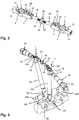
- Fig. 1:
- shows a perspective exploded view of the coupling device according to an embodiment.
- Fig. 2:
- shows a perspective view of the coupling device of
Fig. 1 in an assembled state. - Fig. 3:
- shows a perspective view of the coupling device of
Figs. 1 and2 attached to bone anchor extensions that are fixed to bone anchors inserted into the pedicles of a vertebra. - Fig. 4:
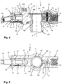
- shows a cross-sectional view of one part of the coupling device of
Figs. 1 to 3 attached to one bone anchor extension, wherein the section is taken in a plane spanned by an axis of connection and a central axis of the bone anchor extension. - Fig. 5:
- shows a cross-sectional view of the part of the coupling device shown in
Fig. 4 , wherein the cross-section is taken in a plane containing the connection axis and perpendicular to a central axis of the bone anchor extension. - Fig. 6:
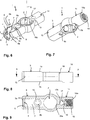
- shows a perspective view from the top of a coupling body of the coupling device according to
Figs. 1 to 5 . - Fig. 7:
- shows a perspective view from the bottom of the coupling body of
Fig. 6 . - Fig. 8:
- shows a side-view of the coupling body of
Figs. 6 and 7 . - Fig. 9:
- shows a cross-sectional view of the coupling body of
Figs. 6 to 8 along line A-A inFig. 8 . - Fig. 10:
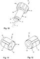
- shows a perspective view of a locking member for locking a pivot position of a connection member relative to the coupling body in the coupling device of
Figs. 1 to 5 . - Fig. 11:
- shows a perspective view from the front of a pressure member for locking a pivot position in the coupling device of
Figs. 1 to 5 . - Fig. 12:
- shows a perspective view from the rear of the pressure member of
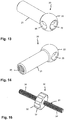
Fig. 11 . - Fig. 13:
- shows a perspective view from the front of a connection member of the coupling device of
Figs. 1 to 5 . - Fig. 14:
- shows a perspective view from the rear of the connection member of
Fig. 13 . - Fig. 15:
- shows a perspective view of a length adjustment member that is part of the coupling device of
Figs. 1 to 5 . - Referring to
Figs. 1 to 3 , a coupling device according to an embodiment includes afirst coupling body 1 and a second coupling body 1' that are connected by a connection device that includes afirst connection member 20, a second connection member 20' and alength adjustment member 30. Thelength adjustment member 30 is arranged between thefirst connection member 20 and the second connection member 20'. The first andsecond coupling bodies 1, 1' are configured to be connected to bone anchors 100, 100', respectively, viabone anchor extensions 101, 101'. - The bone anchors 100, 100' may have a shank for anchoring in bone and a head (not shown in detail). Exemplary, the bone anchors 100, 100' may be designed as polyaxial bone anchors wherein the head is pivotably held in a receiving part that has a U-shaped recess for receiving a
stabilization rod 200. Thebone anchor extensions 101, 101' may be sleeve-shaped with an invertedU-shaped recess 102 to permit therod 200 to be guided there through. In addition, thebone anchor extensions 101, 101' may be detachably mountable to the bone anchors 100, 100'. Preferably, thebone anchor extensions 101, 101' may have such a length that they extend out of a patient's skin in the case that minimally invasive surgery is performed. In addition, their inner diameter may be such that instruments and/or parts of a bone anchor, for example a locking member, can be passed through to lock a polyaxial position of the bone anchor. - As shown more in detail in
Figs. 4 and 5 , the first andsecond coupling bodies 1, 1' are configured to connectfree end portions 103 of thebone anchor extensions 101, 101'. The outer shape of theend portion 103 of thebone anchor extensions 101, 101' may have a polygonal contour, for example an octagonal contour. Furthermore, in the outer surface of theend portion 103 acircumferential groove 104 is formed which functions as an engagement structure for a locking member for locking the connection between thebone anchor extension 101, 101' and the first andsecond coupling body 1, 1', respectively. Thecircumferential groove 104 may have a substantially circular-segment shaped contour in a sectional plane that extends radially from the sleeve axis s. Preferably, thegroove 104 may be located in an axial direction approximately halfway between the free end and anannular step 103a. - As can be seen additionally more in detail in
Figs. 6 to 9 , each of thecoupling bodies 1, 1' is a substantially elongate part having atop surface 1a and an oppositebottom surface 1b and a sleeve-shapedopening 2 extending from thetop surface 1a to thebottom surface 1b. The sleeve shaped-opening 2 is configured to fit onto thefree end portion 103 of each of thebone anchor extensions 101, 101'. The first and the second coupling body are identical. As can be seen in particular inFig. 4 , theannular step 103a of the bone anchor extension forms an abutment for the first andsecond coupling body 1, 1' when placed onto theend portion 103 of thebone anchor extension 101, 101'. An inner wall defining the sleeve-shapedopening 2 has a polygonal inner contour, theedges 2a of which may be rounded. Thereby, a form fit connection with theend portion 103 of thebone anchor extension 101, 101' can be established. Theannular step 103a may be at such a distance from the free end of thebone anchor extension 101, 101' that in the mounted state of thecoupling body 1, 1' the free end of thebone anchor extension 101, 101' and thecoupling body 1, 1' are substantially flush with each other. An outer contour of the first andsecond coupling body 1, 1' in the region of the sleeve-shapedopening 2 may be spherical segment-shaped, or otherwise rounded or may have any other shape. - From the sleeve-shaped
opening 2, a first orinner arm 3 extends to one side in a direction perpendicular to the sleeve axis s. It shall be noted that in the mounted state, the sleeve axis s of the bone anchor extension and that of the sleeve shaped opening are coaxial and thetop surface 1a faces away from the free end of the bone anchor extension. Theinner arm 3 has a freeouter end 3a that faces toward the respective other one of the first andsecond coupling bodies 1, 1'. Ahollow passage 7 extends completely through thearm 3 from the sleeve-shapedopening 2 towards thefree end 3a in a direction perpendicular to the sleeve axis s. Adjacent to thefree end 3a in the passage, a receivingportion 4 for accommodating anend portion 22 of theconnection member 20, 20' is provided. The receivingportion 4 comprises asupport surface 5 that is shaped so as to allow a pivoting movement of anend portion 22 of theconnection member 20, 20' which is described more in detail below. In the example shown, thesupport surface 5 has a spherical shape that cooperates with a ball-shapedend portion 22 of theconnection member 20, 20'. However, any other surface, e.g. a conically tapering surface that allows a pivoting movement may be also provided. In thetop surface 1a of theinner arm 3 a cut-out 6 is formed that provides access to the receivingportion 4. The cut-out 6 has anarrower portion 6a adjacent to thefree end 3a which is narrower than a width of theend portion 22 of theconnection member 20, 20' so that theend portion 22 can neither be inserted at thenarrower portion 6a nor be removed through thefree end 3a. Hence, the end portion of theconnection member 20, 20' can be pivotably captured in the receivingportion 4. The cut-out 6 further comprises a widenedportion 6b with substantially flat side walls that has a width greater than a maximum width of theend portion 22 of theconnection member 20, 20' and that permits to insert theend portion 22 and to move it into the receivingportion 4. - At a position between the receiving
portion 4 and the sleeve-shapedopening 2 anupper opening 8a and alower opening 8b having a smaller width that theupper opening 1a, are provided in thetop surface 1a and thebottom surface 1b, respectively. Theopenings member 40 for locking the pivot position of theconnection member 20, 20' in the receivingportion 4 explained more in detail below. Moreover, as shown inFigs. 4 and6 , thepassage 7 is configured to accommodate apressure member 50 that serves for transferring pressure from the lockingmember 40 onto theend portion 22 of theconnection member 20, 20'. Between theupper opening 8a and the cut-out 6, asmall roof 9 is formed by thetop surface 1a of theinner arm 3 that is configured to cover a portion of thepressure member 50. Therefore, in the mounted state as shown inFig. 4 , thepressure member 50 cannot escape from theinner arm 3. In theroof 9 and the sidewalls of thearm 3,further cutouts 9a may be provided to provide space for the insertion of thepressure member 50. Above theopening 8b, arecess 10 may be formed in the inner wall of theinner arm 3 that allows a portion of the lockingmember 40 to extend therein. - As can be seen in
Figs. 6 to 8 , thetop surface 1a and thebottom surface 1b of the coupling body at a position of theinner arm 3 may be flat and theinner arm 3 may have a height that is greater than a height of the portion with the sleeve-shapedopening 2. An outer side wall of theinner arm 3 between thetop surface 1a and thebottom surface 1b may be cylindrically shaped. Moreover, close to thefree end 3a there arepin holes 12 provided on opposite sides from the cut-out 6 that extend perpendicular to the sleeve axis s. The pin holes 12 serve for receiving a pin 13 (Fig. 5 ) therein that may extend through theend portion 22 of theconnection member 20, 20' for securing theend portion 22 in the receivingportion 4. - On the side of the sleeve-shaped
opening 2 opposite to theinner arm 3 an second orouter arm 14 is formed. A longitudinal axis of theouter arm 14 is substantially perpendicular to the sleeve axis s and may be coaxial with a longitudinal axis of the innerinner arm 3. Theouter arm 14 comprises afree end 14a from which a threadedbore 15 that is coaxial with the longitudinal axis of theouter arm 14 extends to a distance from thefree end 14a. Between the bottom of the coaxial threaded bore 15 and the sleeve-shapedopening 2 a further coaxial bore 16 is provided that has a smaller width than the coaxial threaded bore 15. Thecoaxial bore 16 is connected through anopening 16a with the sleeve-shapedopening 2. Theopening 16a has a smaller width than thecoaxial bore 16. Approximately halfway between theopening 16a and the bottom of the coaxial threaded bore 15 acylindrical bore 17 is provided that extends perpendicularly to the longitundinal axis of theouter arm 14 from thetop surface 1a to a distance from thebottom surface 1b. At the side closer to the sleeve-shapedopening 2 a furthersmaller bore 17b is provided that opens into thebottom surface 1b. Thebore 17b may, e.g., facilitate the cleaning process of the device. - The
coaxial bore 16 adjacent to theopening 16a serves for accommodating a ball 18 a diameter of which is such that the ball can slide in thebore 16 and extend partially through theopening 16a. Moreover, apin hole 19 is formed in one side of the theouter arm 14 in a direction perpendicular to the sleeve axis s and at a height position between thetop surface 1a and thecoaxial bore 16. Thepin hole 19 is located in the region of thecoaxial bore 17 so that apin 60 that is placed in thepin hole 19 extends into thebore 17. Thepin 60 may serve as a securing device for preventing an actuatingmember 70 provided in thebore 17 from being removed inadvertently. - The actuating
member 70 comprises a firstcylindrical portion 71 that can slide in thebore 17 and anactuating knob 72 that extends out from thetop surface 1a and has a greater width than thebore 17. The firstcylindrical portion 71 comprises in its outer surface acircumferential groove 71a that is sized so as to allow a portion of theball 18 to be received therein. Between the firstcylindrical portion 71 and the actuating knob 72 a reduceddiameter neck 73 may be provided. Inside the actuatingmember 70 there is a coaxial cylindrical bore that receives a biasing member, such as ahelical spring 74. In the mounted state shown e.g. inFig. 4 , the biasing member urges the actuatingknob 72 away from thetop surface 1a such that the firstcylindrical portion 71 urges theball 18 into theopening 16a where it can extend into thegroove 104 of theend portion 103. Once theball 18 engages thegroove 104, thecoupling body 1, 1' is locked in an axial direction to thebone anchor extension 101, 101'. Pushing theactuating knob 72 toward thebottom surface 1b results in a compression of thespring 74 such that theball 18 can wander into thegroove 71a of thecylindrical portion 71. By means of this, the locking is released. Hence, theball 18 actuated with the aid of a biasing member forms an engagement structure that resiliently cooperates with an engagement structure at the bone anchor extension. - Like the
inner arm 3, theouter arm 14 may have cylindrical side surfaces between the top and the bottom surface. Thebottom surface 1b may have a step towards thefree end 14a. - As depicted in more detail in
Fig. 10 , the lockingmember 40 is formed as an eccentric device. It comprises a substantiallycylindrical shaft 41 that defines an axis of rotation R, wherein theshaft 41 is rotated via arotation knob 42 or rotation wheel. Between therotation knob 42 and theshaft 41 an cylindricaleccentric portion 43 is provided the cylinder axis c of which is parallel to the axis of rotation R. Hence, when rotating theshaft 41 with theknob 42, the cylinder axis c of theeccentric portion 43 rotates around the axis of rotation R of theshaft 41. At a distance from the free end of the shaft 41 agroove 44 is formed that serves for receiving a securingclip 45. Between theeccentric portion 43 and the actuatingknob 42 a disk-shapedprojection 46 with an outer diameter smaller than that of theknob 42 and greater than that of theeccentric portion 43 may be provided. The lockingmember 40 has such a size that when it is mounted to theinner arm 3 theeccentric portion 43 extends through thepassage 7 and theshaft 41 with thegroove 44 extends through thelower opening 8b. When the lockingmember 40 is mounted to theinner arm 3, the disk-shapedprojection 46 may rest on theroof 9 and theknob 42 extends above thetop surface 1a. Hence, theknob 42 of the lockingmember 40 and theknob 72 of the actuatingmember 70 protrude both above thetop surface 1a. This facilitates handling of the device. In the mounted state theeccentric portion 43 can extend at its lower side into therecess 10. Once the securingclip 45 is provided in thegroove 44, the lockingmember 40 is rotatably held in theinner arm 3. - In the free end surface of the
rotating knob 42 anengagement recess 42a may be formed for actuating the lockingmember 40 with a driver, for example. Alternatively, theknob 42 can be rotated by hand using agripping structure 42b, for example longitudinal grooves. - The
pressure member 50 is shown in more detail inFigs. 11 and 12 . It is a substantially cylindrical part with an outer diameter that permits it to slide within thepassage 7 and under theroof 9. At one free end a substantially spherically-shapedrecess 51 is formed that matches the outer shape of theend portion 22 of theconnection member 20, 20'. By means of this, pressure can be distributed onto theend portion 22. At the other free end opposite to the spherically-shaped recess 51 a reduceddiameter section 52 may be provided that may have the function of facilitating insertion of thepressure member 50 into thepassage 7. Acoaxial bore 53 may extend completely through thepressure member 50 from one end to the opposite end. Moreover,longitudinal grooves 54 may be formed in the outer surface of thepressure member 50 to facilitate cleaning. Thepressure member 50 has such an axial length that it fills the space between the lockingmember 40 and theend portion 22 of theconnection members inner arm 3 in such a manner that the spherically-shapedrecess 51 contacts theend portion 22 of theconnection member 20, 20'. - Next, with additionally reference to
Figs. 13 and 14 , theconnection members connection member 20, 20' comprise acylindrical shaft portion 21 and a ball-shapedend portion 22. An outer diameter of the ball-shapedend portion 22 may be greater than the outer diameter of theshaft 21 and furthermore, may be such that the ball-shapedend portion 22 can be pivotably held in the receivingportion 4 of theinner arm 3. Theconnection member 20, 20' may have a longitudinal passage 23 that extends through the connection member completely from the free end of theshaft 21 through theend portion 22. Adjacent to the free end of theshaft 21, the passage 23 comprises aninternal thread 24, 24' over an axial length of theshaft 21 that permits in cooperation with thelength adjustment member 30 to vary the distance between theconnection members 20, 20' to a necessary extent. The direction of theinternal threads 24, 24' is different for thefirst connection member 20 and the second connection member 20'. For example, theinternal thread 24 of thefirst connection member 20 may be a right-hand thread and the internal thread 24' of the second connection member 20' may be a left-hand thread. In addition,transverse holes 25 are provided in the ball-shapedend portion 22 that are arranged perpendicularly to the longitudinal passage 23 and on opposite sides. Theholes 25 may taper towards a center of the ball-shapedend portion 22. When the ball-shapedend portion 22 is received in the receivingportion 4 of theinner arm 3, thepin 13 can extend through the pin holes 12 of theinner arm 3 and through the transverse holes 25. Due to the tapered shape, the ball-shapedend portion 22 can pivot in the receivingportion 4 until thepin 13 abuts against the tapered wall of the transverse holes 25. Hence, theholes 25 with thepin 13 are configured to limit the pivoting movement of the ball-shapedend portion 22 in the receivingportion 4. - The
length adjustment member 30 as depicted inFigs. 1 to 3 and15 , includes ashaft 31. At the center of theshaft 31 in a longitudinal direction of the shaft axis, an actuatingknob 32 or wheel is provided that can be gripped by hand and that preferably has a grippingstructure 33, for example longitudinal grooves. On the shaft portions extending to the right side and to the left side from the actuatingknob 32 in each case anexternal thread 34, 34' is provided that is configured to cooperate with the respectiveinternal thread 24, 24' of theconnection members 20, 20'. When thelength adjustment member 30 is mounted between thefirst connection member 20 and the second connection member 20', the shaft axis of theshaft 31 defines a connection axis. - Optionally, as depicted in
Fig. 3 , ahandle 80 can be mounted to each of theouter arms 14 of the first andsecond coupling bodies 1, 1'. Thehandle 80 may have a threadedshaft 81 that can be screwed into the threadedhole 15 of theouter arm 14 and agrip portion 82. Thehandle 80 is not essential for the functioning of the coupling device but may be used during the surgical correction step. - The
pressure member 50 and theconnection member 20, 20' may be mounted to theinner arm 3 of thecoupling bodies 1, 1' one after another by inserting them through the widenedportion 6b of thecutout 6. - The parts and portions of the coupling device may be made of any material, preferably, however of bio-compatible materials, for example of titanium or stainless steel, of a bio-compatible alloy, such as NiTi-alloys, for example Nitinol, of magnesium or magnesium alloys, or from a bio-compatible plastic material, such as, for example polyether ether ketone (PEEK) or poly-L-lactide acid (PLLA). In addition, the parts can be made of the same as or of different materials from another.
- In operation, the coupling device is placed on the
bone anchor extensions 101, 101' that are fixed to bone anchors 100, 100'. The bone anchors 100, 100' may be, for example, pedicle screws. The coupling device is usually preassembled. Before placing the coupling device onto thebone anchor extensions 101, 101', theconnection members 20, 20' are in the pivotable configuration. When placing thecoupling bodies 1, 1' with the sleeve-shapedopening 2 onto thebone anchor extensions 101, 101', respectively, theactuating button 72 is pushed down to release theball 18 so that it does no longer protrude through theopening 16a. The first and thesecond coupling bodies 1, 1' are placed onto theend portions 103 of thebone anchor extension 101, 101', respectively. During this step, theball 18 snaps into thegroove 104 of theend portion 103. Moreover, the form fit connection between theend portion 103 of the bone anchor extension and the sleeve-shapedopening 2 due to the polygonal shape secures thecoupling body 1, 1' against rotation Then thebutton 72 is released so that theball 18 is pressed into thegroove 104 thereby locking the first andsecond coupling body 1, 1' to thebone anchor extensions 101, 101'. Since theend portions 22 of theconnection members 20, 20' can pivot in the receivingportion 4 of thecoupling bodies 1, 1', the coupling device can be adapted to the position of thebone anchor extensions 101, 101' in the spatial directions. - The length of the coupling device can be adjusted by rotating the actuating
knob 32 of thelength adjustment member 30. Rotating theknob 32 in one direction increases the distance between theconnection members 20, 20'. Rotating theknob 32 in the opposite direction decreases the distance between theconnection members 20, 20'. Hence, the length of the coupling device can be adjusted with requiring only one hand of a user to hold and rotate theknob 32. - Once the coupling device is placed onto the bone anchor extensions and the distance between the
connection members 20, 20' has been adjusted, the pivot position of theconnection members 20, 20' can be locked using the lockingmember 40. As shown inFig. 5 , theeccentric portion 43 of the lockingmember 40 has a first position where it is farthest away from thepressure member 50 so that it cannot exert sufficient pressure onto the pressure member to lock theend portion 22. By rotating the actuatingknob 42 of the locking member, theeccentric portion 43 presses onto thepressure member 50 so that once it has the closest position to thepressure member 50, sufficient pressure is exerted onto theend portion 22 to lock the pivot position of theconnection member 20, 20'. Locking and releasing can be effected by rotation the locking member in one direction or in the opposite direction. - Finally, the desired correction step can be carried out. This can be, for example, a step of rotating the vertebra relative to other vertebrae. The
handles 80 may be used to perform this step. - In a further development, at least two or more coupling devices may be mounted to bone anchor extensions on adjacent vertebrae and coupled by connectors so that the coupling devices form an assemblage. By means of this, more than one vertebra, even a plurality of vertebrae can be corrected simultaneously together.
- Modifications of the coupling device may be conceivable. It shall be noted that the length adjustment of the coupling device may be realized using another advancement structure that permits to simultaneously increase and decrease the distance between the connection members. Also, the specific shape of the single parts of the coupling device is not limited to the shape as explained in connection with the above embodiment. Deviations may be possible. The optional handles may be attached to the coupling device and fixed thereto by any other means.
- The bone anchor extension may be part of the bone anchor itself, for example in the form of extended legs of a receiving part of a polyaxial bone anchor which may be broken away after the correction steps have been performed. Hence, the invention also relates to a system comprising the coupling device and to bone anchors and corresponding bone anchor extension.
Claims (15)
- A coupling device, in particular for use in orthopedic surgery, the coupling device including
a first coupling body (1) that is configured to be coupled to a first bone anchor (101), a second coupling body (1') that is configured to be coupled to a second bone anchor (101'),
a connection device (20, 20', 30) that is configured to connect the first coupling body (1) and the second coupling body (1'), wherein the connection device includes a first connection member (20) and a second connection member (20') a distance of which along a connection axis is adjustable and a length adjustment member (30) that is configured to be actuated in a first direction whereby the distance between the first connection member (20) and the second connection member (20') is increased and in a second direction whereby the distance between the first connection member (20) and the second connection member (20') is decreased
wherein the first and second connection members (20, 20') each include a longitudinal passage (23) extending through the connection member and an advancement structure (24, 24') in the passage (23) that allows to gradually adjust the distance between the first and second connection member (20, 20') and wherein the length adjustment member (30) comprises a first extension cooperating with the first connection member (20) and a second extension cooperating with the second connection member (20'), and advancement structures (34, 34') on the first and second extension mating with the advancement structures (24, 24') of the first and second connection members (20, 20'), respectively. - The coupling device of claim 1, wherein the advancement structure (24, 24') in the longitudinal passage (23) of the connection members (20, 20') is a thread and wherein the advancement structures (34, 34') on the first and second extension of the length adjustment member (30) are threads.
- The coupling device of claim 1 or 2, wherein the first extension comprises a right-hand thread (34) cooperating with the first connection member (20) and the second extension comprises a left-hand thread (34') cooperating with the second connection member (20') such that when the length adjustment member (30) is rotated in one direction the distance between the first and second connection members (20, 20') increases and when it is rotated in the opposite direction the distance decreases.
- The coupling device of one of claims 1 to 3, wherein at least the first, preferably both of the first and second connection members (20, 20') are configured to pivot with respect to the first and second coupling body (1, 1').
- The coupling device of one of claims 1 to 4, wherein at least the first, preferably both of the first and second coupling bodies (1, 1') comprises a receiving portion (4) that is configured to pivotably receive an end portion (22) of the first, preferably both of the first and second connection members (20, 20'), respectively, therein and wherein the end portion (22) is insertable into the receiving portion (4) and captured therein.
- The coupling device of one of claims 4 or 5, wherein a pressure member (50) is provided for locking a pivot position of the first and/or second connection member (20, 20') relative to the first or second coupling body (1, 1').
- The coupling device of one of claims 4 to 6, wherein a locking member (40) is provided for locking and releasing a pivot position of the connection member (20, 20').
- The coupling device of claims 7, wherein the locking member (40) is in the form of an eccentric member (43).
- The coupling device of claim 8, wherein the eccentric member (43) can assume a first configuration in which it locks the connection member (20, 20') and a second configuration in which it releases the connection member (20, 20') and wherein the eccentric member (43) is moved from the first configuration to the second configuration by rotating the locking member (40).
- The coupling device of claim 6 and one of claims 8 and 9, wherein the eccentric member (43) acts onto the pressure member (50).
- The coupling device of claim 5 and one of claims 8 and 9, wherein the connection member (20, 20') defines a connection axis and wherein an axis of rotation (c) of the eccentric member (43) is transverse to the connection axis when the connection member (20, 20') is at zero angle position relative to a longitudinal axis of the receiving portion (4).
- The coupling device of claim 11, wherein the axis of rotation (c) of the eccentric member (43) is substantially perpendicular to the connection axis when the connection member (20, 20') is at zero angle position relative to a longitudinal axis of the receiving portion (4).
- The coupling device of one of claims 1 to 12, wherein each of the first and second coupling bodies (1, 1') comprises a sleeve shaped opening (2) for coupling to a bone anchor (100, 100') or a bone anchor extension (101, 101').
- The coupling device of claim 13, wherein each of the first and the second coupling bodies (1, 1') includes an engagement structure configured to resiliently cooperate with an engagement structure on the bone anchor or a bone anchor extension (101, 101') to provide a connection between the first and second coupling body (1, 1') and the bone anchor or a bone anchor extension (100, 100').
- The coupling device of claim 14, wherein the engagement structure of the first and second coupling body (1, 1') is a separate engagement member (18) that is urged via a biasing member (74) into engagement with a recess (104) provided in an outer surface of the bone anchor or bone anchor extension (101, 101').
Priority Applications (2)
| Application Number | Priority Date | Filing Date | Title |
|---|---|---|---|
| EP18210576.7A EP3662853B1 (en) | 2018-12-05 | 2018-12-05 | Coupling device, in particular for use in orthopedic surgery |
| US16/700,502 US11224462B2 (en) | 2018-12-05 | 2019-12-02 | Coupling device, in particular for use in orthopedic surgery |
Applications Claiming Priority (1)
| Application Number | Priority Date | Filing Date | Title |
|---|---|---|---|
| EP18210576.7A EP3662853B1 (en) | 2018-12-05 | 2018-12-05 | Coupling device, in particular for use in orthopedic surgery |
Publications (2)
| Publication Number | Publication Date |
|---|---|
| EP3662853A1 EP3662853A1 (en) | 2020-06-10 |
| EP3662853B1 true EP3662853B1 (en) | 2021-07-21 |
Family
ID=64650165
Family Applications (1)
| Application Number | Title | Priority Date | Filing Date |
|---|---|---|---|
| EP18210576.7A Active EP3662853B1 (en) | 2018-12-05 | 2018-12-05 | Coupling device, in particular for use in orthopedic surgery |
Country Status (2)
| Country | Link |
|---|---|
| US (1) | US11224462B2 (en) |
| EP (1) | EP3662853B1 (en) |
Families Citing this family (5)
| Publication number | Priority date | Publication date | Assignee | Title |
|---|---|---|---|---|
| US11849981B2 (en) | 2019-01-30 | 2023-12-26 | Medos International Sarl | Systems and methods for en bloc derotation of a spinal column |
| WO2022035896A1 (en) * | 2020-08-10 | 2022-02-17 | In2Bones Usa, Llc | Metatarsal alignment apparatus |
| US11617603B2 (en) | 2020-12-09 | 2023-04-04 | Warsaw Orthopedic, Inc. | Modular surgical instrument system with ratcheting reduction mechanism |
| US11406431B1 (en) | 2021-05-10 | 2022-08-09 | Warsaw Orthopedic, Inc. | Systems and methods of use and modular instruments with a lateral reducer |
| WO2024039802A1 (en) * | 2022-08-17 | 2024-02-22 | Xfix8 Llc | External fixation devices, systems, and methods |
Family Cites Families (9)
| Publication number | Priority date | Publication date | Assignee | Title |
|---|---|---|---|---|
| US4771767A (en) * | 1986-02-03 | 1988-09-20 | Acromed Corporation | Apparatus and method for maintaining vertebrae in a desired relationship |
| DE8712943U1 (en) * | 1987-09-25 | 1987-11-12 | Aesculap-Werke Ag Vormals Jetter & Scheerer, 7200 Tuttlingen, De | |
| DE3807335A1 (en) * | 1988-03-05 | 1989-09-14 | Orthoplant Endoprothetik | Repositioning and distraction apparatus |
| DE9112466U1 (en) * | 1991-10-07 | 1991-12-05 | Howmedica Gmbh, 2314 Schoenkirchen, De | |
| DE10136162B4 (en) | 2001-07-25 | 2016-05-12 | Biedermann Technologies Gmbh & Co. Kg | Connecting element for connecting two used for bone and spine stabilization rod-shaped elements |
| JP2011526194A (en) * | 2008-06-27 | 2011-10-06 | ケー2エム, インコーポレイテッド | System and method for performing spinal surgery |
| US9198696B1 (en) * | 2010-05-27 | 2015-12-01 | Nuvasive, Inc. | Cross-connector and related methods |
| US9101412B2 (en) * | 2010-09-09 | 2015-08-11 | DePuy Synthes Products, Inc. | Vertebral adjustment systems for spine alignment |
| US10098665B2 (en) | 2012-08-01 | 2018-10-16 | DePuy Synthes Products, Inc. | Spine derotation system |
-
2018
- 2018-12-05 EP EP18210576.7A patent/EP3662853B1/en active Active
-
2019
- 2019-12-02 US US16/700,502 patent/US11224462B2/en active Active
Non-Patent Citations (1)
| Title |
|---|
| None * |
Also Published As
| Publication number | Publication date |
|---|---|
| US11224462B2 (en) | 2022-01-18 |
| US20200179008A1 (en) | 2020-06-11 |
| EP3662853A1 (en) | 2020-06-10 |
Similar Documents
| Publication | Publication Date | Title |
|---|---|---|
| EP3662853B1 (en) | Coupling device, in particular for use in orthopedic surgery | |
| US9820779B2 (en) | Spinal stabilization system | |
| AU2012201463B2 (en) | Polyaxial pedicle screw and fixation system kit comprising said screw | |
| US7578822B2 (en) | Instrument for compression or distraction | |
| US7967848B2 (en) | Spring-loaded dynamic pedicle screw assembly | |
| US8246625B2 (en) | Reducing instrument for spinal surgery | |
| US8986349B1 (en) | Systems and methods for correcting spinal deformities | |
| US9788869B2 (en) | Spinal fixation element rotation instrument | |
| EP2460483B1 (en) | Surgical instrument | |
| EP2730242B1 (en) | Spine stabilization system | |
| US9173687B2 (en) | Fulcrum cap for spinal constructs | |
| US10973552B2 (en) | Surgical system for bone screw insertion and rod reduction | |
| JP2012504029A (en) | Multi-axis bottom loading screw and rod assembly | |
| US11737791B2 (en) | System and instrument for correcting a position of bones, bone parts, or vertebrae | |
| EP3949881B1 (en) | System of a rod insertion device and a rod | |
| EP3127499A1 (en) | Instrument for correcting a position of one or more vertebrae of the spine | |
| AU2016203448B2 (en) | Surgical system for bone screw insertion and rod reduction | |
| AU2015203073B2 (en) | Spinal stabilization system | |
| CN116963684A (en) | Multi-feature multi-shaft screw |
Legal Events
| Date | Code | Title | Description |
|---|---|---|---|
| PUAI | Public reference made under article 153(3) epc to a published international application that has entered the european phase |
Free format text: ORIGINAL CODE: 0009012 |
|
| STAA | Information on the status of an ep patent application or granted ep patent |
Free format text: STATUS: THE APPLICATION HAS BEEN PUBLISHED |
|
| STAA | Information on the status of an ep patent application or granted ep patent |
Free format text: STATUS: REQUEST FOR EXAMINATION WAS MADE |
|
| AK | Designated contracting states |
Kind code of ref document: A1 Designated state(s): AL AT BE BG CH CY CZ DE DK EE ES FI FR GB GR HR HU IE IS IT LI LT LU LV MC MK MT NL NO PL PT RO RS SE SI SK SM TR |
|
| AX | Request for extension of the european patent |
Extension state: BA ME |
|
| 17P | Request for examination filed |
Effective date: 20200522 |
|
| RBV | Designated contracting states (corrected) |
Designated state(s): AL AT BE BG CH CY CZ DE DK EE ES FI FR GB GR HR HU IE IS IT LI LT LU LV MC MK MT NL NO PL PT RO RS SE SI SK SM TR |
|
| GRAP | Despatch of communication of intention to grant a patent |
Free format text: ORIGINAL CODE: EPIDOSNIGR1 |
|
| STAA | Information on the status of an ep patent application or granted ep patent |
Free format text: STATUS: GRANT OF PATENT IS INTENDED |
|
| INTG | Intention to grant announced |
Effective date: 20201116 |
|
| GRAJ | Information related to disapproval of communication of intention to grant by the applicant or resumption of examination proceedings by the epo deleted |
Free format text: ORIGINAL CODE: EPIDOSDIGR1 |
|
| STAA | Information on the status of an ep patent application or granted ep patent |
Free format text: STATUS: REQUEST FOR EXAMINATION WAS MADE |
|
| GRAP | Despatch of communication of intention to grant a patent |
Free format text: ORIGINAL CODE: EPIDOSNIGR1 |
|
| INTC | Intention to grant announced (deleted) | ||
| STAA | Information on the status of an ep patent application or granted ep patent |
Free format text: STATUS: GRANT OF PATENT IS INTENDED |
|
| INTG | Intention to grant announced |
Effective date: 20210311 |
|
| GRAS | Grant fee paid |
Free format text: ORIGINAL CODE: EPIDOSNIGR3 |
|
| GRAA | (expected) grant |
Free format text: ORIGINAL CODE: 0009210 |
|
| STAA | Information on the status of an ep patent application or granted ep patent |
Free format text: STATUS: THE PATENT HAS BEEN GRANTED |
|
| AK | Designated contracting states |
Kind code of ref document: B1 Designated state(s): AL AT BE BG CH CY CZ DE DK EE ES FI FR GB GR HR HU IE IS IT LI LT LU LV MC MK MT NL NO PL PT RO RS SE SI SK SM TR |
|
| REG | Reference to a national code |
Ref country code: GB Ref legal event code: FG4D |
|
| REG | Reference to a national code |
Ref country code: CH Ref legal event code: EP |
|
| REG | Reference to a national code |
Ref country code: DE Ref legal event code: R096 Ref document number: 602018020378 Country of ref document: DE |
|
| REG | Reference to a national code |
Ref country code: AT Ref legal event code: REF Ref document number: 1411877 Country of ref document: AT Kind code of ref document: T Effective date: 20210815 |
|
| REG | Reference to a national code |
Ref country code: IE Ref legal event code: FG4D |
|
| REG | Reference to a national code |
Ref country code: LT Ref legal event code: MG9D |
|
| REG | Reference to a national code |
Ref country code: NL Ref legal event code: MP Effective date: 20210721 |
|
| REG | Reference to a national code |
Ref country code: AT Ref legal event code: MK05 Ref document number: 1411877 Country of ref document: AT Kind code of ref document: T Effective date: 20210721 |
|
| PG25 | Lapsed in a contracting state [announced via postgrant information from national office to epo] |
Ref country code: RS Free format text: LAPSE BECAUSE OF FAILURE TO SUBMIT A TRANSLATION OF THE DESCRIPTION OR TO PAY THE FEE WITHIN THE PRESCRIBED TIME-LIMIT Effective date: 20210721 Ref country code: SE Free format text: LAPSE BECAUSE OF FAILURE TO SUBMIT A TRANSLATION OF THE DESCRIPTION OR TO PAY THE FEE WITHIN THE PRESCRIBED TIME-LIMIT Effective date: 20210721 Ref country code: HR Free format text: LAPSE BECAUSE OF FAILURE TO SUBMIT A TRANSLATION OF THE DESCRIPTION OR TO PAY THE FEE WITHIN THE PRESCRIBED TIME-LIMIT Effective date: 20210721 Ref country code: FI Free format text: LAPSE BECAUSE OF FAILURE TO SUBMIT A TRANSLATION OF THE DESCRIPTION OR TO PAY THE FEE WITHIN THE PRESCRIBED TIME-LIMIT Effective date: 20210721 Ref country code: ES Free format text: LAPSE BECAUSE OF FAILURE TO SUBMIT A TRANSLATION OF THE DESCRIPTION OR TO PAY THE FEE WITHIN THE PRESCRIBED TIME-LIMIT Effective date: 20210721 Ref country code: NL Free format text: LAPSE BECAUSE OF FAILURE TO SUBMIT A TRANSLATION OF THE DESCRIPTION OR TO PAY THE FEE WITHIN THE PRESCRIBED TIME-LIMIT Effective date: 20210721 Ref country code: NO Free format text: LAPSE BECAUSE OF FAILURE TO SUBMIT A TRANSLATION OF THE DESCRIPTION OR TO PAY THE FEE WITHIN THE PRESCRIBED TIME-LIMIT Effective date: 20211021 Ref country code: PT Free format text: LAPSE BECAUSE OF FAILURE TO SUBMIT A TRANSLATION OF THE DESCRIPTION OR TO PAY THE FEE WITHIN THE PRESCRIBED TIME-LIMIT Effective date: 20211122 Ref country code: BG Free format text: LAPSE BECAUSE OF FAILURE TO SUBMIT A TRANSLATION OF THE DESCRIPTION OR TO PAY THE FEE WITHIN THE PRESCRIBED TIME-LIMIT Effective date: 20211021 Ref country code: AT Free format text: LAPSE BECAUSE OF FAILURE TO SUBMIT A TRANSLATION OF THE DESCRIPTION OR TO PAY THE FEE WITHIN THE PRESCRIBED TIME-LIMIT Effective date: 20210721 Ref country code: LT Free format text: LAPSE BECAUSE OF FAILURE TO SUBMIT A TRANSLATION OF THE DESCRIPTION OR TO PAY THE FEE WITHIN THE PRESCRIBED TIME-LIMIT Effective date: 20210721 |
|
| PG25 | Lapsed in a contracting state [announced via postgrant information from national office to epo] |
Ref country code: PL Free format text: LAPSE BECAUSE OF FAILURE TO SUBMIT A TRANSLATION OF THE DESCRIPTION OR TO PAY THE FEE WITHIN THE PRESCRIBED TIME-LIMIT Effective date: 20210721 Ref country code: LV Free format text: LAPSE BECAUSE OF FAILURE TO SUBMIT A TRANSLATION OF THE DESCRIPTION OR TO PAY THE FEE WITHIN THE PRESCRIBED TIME-LIMIT Effective date: 20210721 Ref country code: GR Free format text: LAPSE BECAUSE OF FAILURE TO SUBMIT A TRANSLATION OF THE DESCRIPTION OR TO PAY THE FEE WITHIN THE PRESCRIBED TIME-LIMIT Effective date: 20211022 |
|
| REG | Reference to a national code |
Ref country code: DE Ref legal event code: R097 Ref document number: 602018020378 Country of ref document: DE |
|
| PG25 | Lapsed in a contracting state [announced via postgrant information from national office to epo] |
Ref country code: DK Free format text: LAPSE BECAUSE OF FAILURE TO SUBMIT A TRANSLATION OF THE DESCRIPTION OR TO PAY THE FEE WITHIN THE PRESCRIBED TIME-LIMIT Effective date: 20210721 |
|
| PLBE | No opposition filed within time limit |
Free format text: ORIGINAL CODE: 0009261 |
|
| STAA | Information on the status of an ep patent application or granted ep patent |
Free format text: STATUS: NO OPPOSITION FILED WITHIN TIME LIMIT |
|
| PG25 | Lapsed in a contracting state [announced via postgrant information from national office to epo] |
Ref country code: SM Free format text: LAPSE BECAUSE OF FAILURE TO SUBMIT A TRANSLATION OF THE DESCRIPTION OR TO PAY THE FEE WITHIN THE PRESCRIBED TIME-LIMIT Effective date: 20210721 Ref country code: SK Free format text: LAPSE BECAUSE OF FAILURE TO SUBMIT A TRANSLATION OF THE DESCRIPTION OR TO PAY THE FEE WITHIN THE PRESCRIBED TIME-LIMIT Effective date: 20210721 Ref country code: RO Free format text: LAPSE BECAUSE OF FAILURE TO SUBMIT A TRANSLATION OF THE DESCRIPTION OR TO PAY THE FEE WITHIN THE PRESCRIBED TIME-LIMIT Effective date: 20210721 Ref country code: EE Free format text: LAPSE BECAUSE OF FAILURE TO SUBMIT A TRANSLATION OF THE DESCRIPTION OR TO PAY THE FEE WITHIN THE PRESCRIBED TIME-LIMIT Effective date: 20210721 Ref country code: CZ Free format text: LAPSE BECAUSE OF FAILURE TO SUBMIT A TRANSLATION OF THE DESCRIPTION OR TO PAY THE FEE WITHIN THE PRESCRIBED TIME-LIMIT Effective date: 20210721 Ref country code: AL Free format text: LAPSE BECAUSE OF FAILURE TO SUBMIT A TRANSLATION OF THE DESCRIPTION OR TO PAY THE FEE WITHIN THE PRESCRIBED TIME-LIMIT Effective date: 20210721 |
|
| 26N | No opposition filed |
Effective date: 20220422 |
|
| PG25 | Lapsed in a contracting state [announced via postgrant information from national office to epo] |
Ref country code: MC Free format text: LAPSE BECAUSE OF FAILURE TO SUBMIT A TRANSLATION OF THE DESCRIPTION OR TO PAY THE FEE WITHIN THE PRESCRIBED TIME-LIMIT Effective date: 20210721 Ref country code: IT Free format text: LAPSE BECAUSE OF FAILURE TO SUBMIT A TRANSLATION OF THE DESCRIPTION OR TO PAY THE FEE WITHIN THE PRESCRIBED TIME-LIMIT Effective date: 20210721 |
|
| REG | Reference to a national code |
Ref country code: BE Ref legal event code: MM Effective date: 20211231 |
|
| PG25 | Lapsed in a contracting state [announced via postgrant information from national office to epo] |
Ref country code: LU Free format text: LAPSE BECAUSE OF NON-PAYMENT OF DUE FEES Effective date: 20211205 Ref country code: IE Free format text: LAPSE BECAUSE OF NON-PAYMENT OF DUE FEES Effective date: 20211205 |
|
| PG25 | Lapsed in a contracting state [announced via postgrant information from national office to epo] |
Ref country code: FR Free format text: LAPSE BECAUSE OF NON-PAYMENT OF DUE FEES Effective date: 20211231 Ref country code: BE Free format text: LAPSE BECAUSE OF NON-PAYMENT OF DUE FEES Effective date: 20211231 |
|
| PGFP | Annual fee paid to national office [announced via postgrant information from national office to epo] |
Ref country code: GB Payment date: 20221223 Year of fee payment: 5 |
|
| PGFP | Annual fee paid to national office [announced via postgrant information from national office to epo] |
Ref country code: CH Payment date: 20230104 Year of fee payment: 5 |
|
| PGFP | Annual fee paid to national office [announced via postgrant information from national office to epo] |
Ref country code: DE Payment date: 20221227 Year of fee payment: 5 |
|
| PG25 | Lapsed in a contracting state [announced via postgrant information from national office to epo] |
Ref country code: CY Free format text: LAPSE BECAUSE OF FAILURE TO SUBMIT A TRANSLATION OF THE DESCRIPTION OR TO PAY THE FEE WITHIN THE PRESCRIBED TIME-LIMIT Effective date: 20210721 |
|
| P01 | Opt-out of the competence of the unified patent court (upc) registered |
Effective date: 20230525 |
|
| PG25 | Lapsed in a contracting state [announced via postgrant information from national office to epo] |
Ref country code: HU Free format text: LAPSE BECAUSE OF FAILURE TO SUBMIT A TRANSLATION OF THE DESCRIPTION OR TO PAY THE FEE WITHIN THE PRESCRIBED TIME-LIMIT; INVALID AB INITIO Effective date: 20181205 |